EP1705339A2 - Rotorwelle, insbesondere für eine Gasturbine - Google Patents
Rotorwelle, insbesondere für eine Gasturbine Download PDFInfo
- Publication number
- EP1705339A2 EP1705339A2 EP06110741A EP06110741A EP1705339A2 EP 1705339 A2 EP1705339 A2 EP 1705339A2 EP 06110741 A EP06110741 A EP 06110741A EP 06110741 A EP06110741 A EP 06110741A EP 1705339 A2 EP1705339 A2 EP 1705339A2
- Authority
- EP
- European Patent Office
- Prior art keywords
- rotor shaft
- cooling air
- rotor
- shaft according
- cavities
- Prior art date
- Legal status (The legal status is an assumption and is not a legal conclusion. Google has not performed a legal analysis and makes no representation as to the accuracy of the status listed.)
- Granted
Links
Images


Classifications
-
- F—MECHANICAL ENGINEERING; LIGHTING; HEATING; WEAPONS; BLASTING
- F01—MACHINES OR ENGINES IN GENERAL; ENGINE PLANTS IN GENERAL; STEAM ENGINES
- F01D—NON-POSITIVE DISPLACEMENT MACHINES OR ENGINES, e.g. STEAM TURBINES
- F01D5/00—Blades; Blade-carrying members; Heating, heat-insulating, cooling or antivibration means on the blades or the members
- F01D5/02—Blade-carrying members, e.g. rotors
- F01D5/08—Heating, heat-insulating or cooling means
- F01D5/081—Cooling fluid being directed on the side of the rotor disc or at the roots of the blades
-
- F—MECHANICAL ENGINEERING; LIGHTING; HEATING; WEAPONS; BLASTING
- F05—INDEXING SCHEMES RELATING TO ENGINES OR PUMPS IN VARIOUS SUBCLASSES OF CLASSES F01-F04
- F05D—INDEXING SCHEME FOR ASPECTS RELATING TO NON-POSITIVE-DISPLACEMENT MACHINES OR ENGINES, GAS-TURBINES OR JET-PROPULSION PLANTS
- F05D2250/00—Geometry
- F05D2250/10—Two-dimensional
- F05D2250/14—Two-dimensional elliptical
Definitions
- the present invention relates to the field of rotary machines. It relates to a rotor shaft, in particular for a gas turbine, according to the preamble of claim 1.
- cooling measures are often provided in order to achieve a sufficient service life of the material used at the high hot gas temperatures.
- Such cooling measures include cooling air ducts which extend approximately in the radial direction from the inside to the outside through the rotor shaft and cooling air from an internal cooling air supply to the surface lead the rotor shaft.
- cooling air ducts represent mechanical weakenings of the rotor shaft, which can have a negative effect on the high temperatures and centrifugal forces and the changing loads.
- An essential point of the present solution is that the cooling air ducts for reducing mechanical stresses have an elliptical cross-section.
- An embodiment of the invention is characterized in that the cooling air channels are arranged distributed over the circumference of the rotor shaft, and that the elliptical cross section of the cooling air channels is oriented in each case so that the large main axis in the circumferential direction and the small main axis are aligned in the axial direction.
- the rotor shaft preferably has a compressor part and a turbine part, and the cooling air passages are arranged in the turbine part.
- Another embodiment of the invention is characterized in that the turbine part has a plurality of rotor disks arranged one behind the other in the axial direction for fastening rotor blades, and in that the cooling air ducts are arranged between adjacent rotor disks.
- cavities are formed concentrically to the rotor axis in the interior of the rotor shaft, and that the cooling air channels emanate from at least one of the cavities and via this cavity with the Cooling air supply communicate. It is then particularly favorable for the cavities to have at least sections an elliptical cross-sectional contour to reduce mechanical stresses on the outer circumference, wherein the cross-sectional contour is preferably composed on the outer circumference of two elliptical sections of two mutually tilted ellipses whose major axes are oriented approximately in the radial direction are.
- Fig. 1 in a perspective side view of a rotor shaft 10 (without blading) reproduced a gas turbine.
- the rotor shaft 10 which is rotationally symmetrical to the rotor axis (17 in FIG. 2), is subdivided into a compressor part 11 and a turbine part 12. Between the two parts 11 and 12, the combustion chamber is arranged inside the gas turbine into which the compressed air in the compressor part 11 is introduced. and from which the hot gas flows through the turbine part 12.
- the turbine part 12 has several rotor disks 13 arranged one behind the other in the axial direction, in which, as shown in FIGS. 3, 4, axially aligned receiving slots 21 are formed around the circumference for receiving corresponding rotor blades.
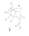
- a plurality of cooling air channels 14 are provided, which depart from a formed inside the rotor shaft 10 cavity 15 approximately radially outward and open at the surface of the rotor shaft 10 in the outer space (Fig 2).
- the cavity 15 communicates with a central, axially extending cooling air supply 16.
- the cooling air passages (14 ') had a circular cross section, the cooling air passages 14 in the new configuration of FIG
- the elliptical cross section of the cooling air ducts 14 can already be predetermined during the casting of the rotor shaft. However, it is also conceivable to introduce such a cross section into the rotor shaft 10 by special machining methods such as eroding.
- the ellipses of the channel cross section of the cooling air ducts 14 are oriented such that the large main axes are oriented in the circumferential direction, while the small main axes are parallel to the rotor axis 17. As a result, a maximum reduction of the mechanical stresses is achieved. It goes without saying that the advantages of an elliptical cross section are not limited to cooling air channels in the rotor shaft itself, but also apply to cooling air channels, which are arranged on other parts of the rotor such as blades or the like.
- the concentric to the rotor axis 17 formed cavity 15 is also optimized in its cross-sectional profile in view of the mechanical stresses occurring.
- the optimization of the cross-sectional profile is carried out in the manner shown in Fig. 5 for further cavities 19, 20 in the compressor part 11 such that the edge contour on the outer periphery of the cavity 15, 19, 20 is at least partially elliptical.
- the cross-sectional contour on the outer circumference - as shown for the cavity 20 in FIG. 5 - is composed of two elliptical sections of two mutually tilted ellipses E1, E2 (shown in dashed lines in FIG. 5) whose major axes are approximately in the radial direction are oriented.
- Such a shape for the cavities present in the interior of the rotor shaft 10 is advantageous not only in connection with the cooling air channels 14 in the turbine part, but can also be used for other cavities 19, 20 which are located, for example, in the compressor part 11 of the rotor shaft 10.
Landscapes
- Engineering & Computer Science (AREA)
- Mechanical Engineering (AREA)
- General Engineering & Computer Science (AREA)
- Turbine Rotor Nozzle Sealing (AREA)
- Structures Of Non-Positive Displacement Pumps (AREA)
Abstract
Description
- Die vorliegende Erfindung bezieht sich auf das Gebiet der rotierenden Maschinen. Sie betrifft eine Rotorwelle, insbesondere für eine Gasturbine, gemäss dem Oberbegriff des Anspruchs 1.
- Bei thermisch und mechanisch hochbelasteten Maschinen, wie sie beispielsweise Verdichter, Gasturbinen oder Dampfturbinen darstellen, ist es wünschenswert, durch eine geeignete konstruktive Auslegung der einzelnen Maschinen- und Anlagenteile mechanische Spannungen zu verringern.
- So ist es aus dem Stand der Technik beispielsweise bekannt (siehe die
EP-A1-0 945 594 oder dieUS-B1-6,478,539 ) bei den Laufschaufeln von Gasturbinen den Übergang vom Schaufelblatt zur darunterliegenden, anschliessenden Plattform der Schaufel mit einer vorausbestimmten, vorzugsweise elliptischen Krümmungskontur auszubilden, wobei die grosse Hauptachse in radialer Richtung verläuft und die kleine Hauptachse parallel zur Oberfläche der Plattform orientiert ist. - Weiterhin ist es aus der
US-B1-6,237,558 bekannt, bestimmte, bezüglich mechanischer Spannungen kritische Stellen des Kurbelgehäuses einer Verbrennungskraftmaschine mit einer Krümmung zu versehen, die einem Kegelschnitt (Ellipse, Hyperbel, Parabel) folgt. - Nicht nur die Laufschaufeln von Turbinen sind aufgrund der hohen Drehzahlen hohen mechanischen Belastungen ausgesetzt, sondern auch die Rotorwelle selbst. Kritische Stellen sind dabei vor allem die auf dem äusseren Umfang angeordneten Nute in der Rotorwelle, die in axialer Richtung verlaufend oder ringförmig umlaufend beispielsweise zur Aufnahme der Schaufelfüsse der Laufschaufeln oder als Teil einer Wellendichtung vorgesehen sein können. Bei solchen Nuten hängen die in der Nut auftretenden Spannungen massgeblich von der Querschnittskontur ab. Aus der
GB-A-2 265 671 US-A-4,818,182 sind ringförmig umlaufende Nuten zur Befestigung von Laufschaufeln bekannt, die eine abgerundete Querschnittskontur aufweisen. Angaben über die Art des Krümmungsverlaufs bzw. den Einfluss der Kontur auf die Spannungen in der Nut werden nicht gemacht. - Im thermisch besonders belasteten Teil des Rotors, dem Turbinenteil, werden häufig zusätzliche Kühlungsmassnahmen vorgesehen, um bei den hohen Heissgastemperaturen eine ausreichende Standzeit des verwendeten Materials zu erreichen. Zu derartigen Kühlmassnahmen gehören Kühlluftkanäle, die näherungsweise in radialer Richtung von innen nach aussen durch die Rotorwelle verlaufen und Kühlluft von einer innenliegenden Kühlluftzuführung zur Oberfläche der Rotorwelle führen. Derartige Kühlluftkanäle stellen jedoch mechanische Schwächungen der Rotorwelle dar, die sich bei den hohen Temperaturen und Fliehkräften und bei den wechselnden Belastungen nachteilig auswirken können.
- Es ist Aufgabe der Erfindung, eine solche mit radialen Kühlluftkanälen ausgestattete Rotorwelle so auszulegen, dass die Schwächungen der Rotorwelle durch die Kühlluftkanäle minimiert oder zumindest deutlich verringert werden.
- Die Aufgabe wird durch die Gesamtheit der Merkmale des Anspruchs 1 gelöst. Ein wesentlicher Punkt der vorliegenden Lösung besteht darin, dass die Kühlluftkanäle zur Verminderung von mechanischen Spannungen einen elliptischen Querschnitt aufweisen.
- Eine Ausgestaltung der Erfindung ist dadurch gekennzeichnet, dass die Kühlluftkanäle über den Umfang der Rotorwelle verteilt angeordnet sind, und dass der elliptische Querschnitt der Kühlluftkanäle jeweils so orientiert ist, dass die grosse Hauptachse in Umfangsrichtung und die kleine Hauptachse in axialer Richtung ausgerichtet sind.
- Vorzugsweise weist die Rotorwelle einen Verdichterteil und einen Turbinenteil aufweist, und die Kühlluftkanäle sind im Turbinenteil angeordnet.
- Eine andere Ausgestaltung der Erfindung zeichnet sich dadurch aus, dass der Turbinenteil mehrere in axialer Richtung hintereinander angeordnete Rotorscheiben für die Befestigung von Laufschaufeln aufweist, und dass die Kühlluftkanäle zwischen benachbarten Rotorscheiben angeordnet sind.
- Insbesondere ist es denkbar, dass im Inneren der Rotorwelle konzentrisch zur Rotorachse Hohlräume ausgebildet sind, und dass die Kühlluftkanäle von wenigstens einem der Hohlräume ausgehen und über diesen Hohlraum mit der Kühlluftzuführung in Verbindung stehen. Es ist dann besonders günstig, dass die Hohlräume zur Verminderung von mechanischen Spannungen am äusseren Umfang zumindest abschnittweise eine elliptische Querschnittskontur aufweisen, wobei sich vorzugsweise die Querschnittskontur am äusseren Umfang aus zwei elliptischen Abschnitten zweier gegeneinander verkippten Ellipsen zusammensetzt, deren grosse Hauptachsen annähernd in radialer Richtung orientiert sind.
- Die Erfindung soll nachfolgend anhand von Ausführungsbeispielen im Zusammenhang mit der Zeichnung näher erläutert werden. Es zeigen
- Fig. 1
- in einer perspektivischen Seitenansicht eine Rotorwelle (ohne Beschaufelung) mit Kühlluftkanälen im Turbinenteil gemäss einem Ausführungsbeispiel der vorliegenden Erfindung;
- Fig. 2
- einen Längsschnitt durch die Rotorwelle aus Fig. 1 im Bereich des Turbinenteils;
- Fig. 3
- den Blick auf einen mit herkömmlichen Kühlluftkanälen ausgestatteten Turbinenteil einer Rotorwelle;
- Fig. 4
- in einer zu Fig. 3 vergleichbaren Darstellung eine Rotorwelle gemäss einem Ausführungsbeispiel der Erfindung; und
- Fig. 5
- im Längsschnitt eine Rotorwelle mit innenliegenden Hohlräumen, die gemäss einem anderen Ausführungsbeispiel der Erfindung am äusseren Umfang mit einer abschnittsweise elliptischen Querschnittskontur versehen sind.
- In Fig. 1 in einer perspektivischen Seitenansicht eine Rotorwelle 10 (ohne Beschaufelung) einer Gasturbine wiedergegeben. Die zur Rotorachse (17 in Fig. 2) rotationssymmetrische Rotorwelle 10 ist unterteilt in einen Verdichterteil 11 und einen Turbinenteil 12. Zwischen den beiden Teilen 11 und 12 ist innerhalb der Gasturbine die Brennkammer angeordnet, in welche die im Verdichterteil 11 verdichtete Luft eingeführt wird, und aus der das Heissgas durch den Turbinenteil 12 strömt. Der Turbinenteil 12 weist in axialer Richtung hintereinander angeordnet mehrere Rotorscheiben 13 auf, in denen gemäss Fig. 3, 4 über den Umfang verteilt axial ausgerichtete Aufnahmeschlitze 21 zur Aufnahme von entsprechenden Laufschaufeln ausgebildet sind. Die Halterung der Schaufelfüsse in den Aufnahmeschlitzen 21 erfolgt in üblicher Weise durch Formschluss mittels einer tannenbaumartigen Querschnittskontur. Im Verdichterteil 11 sind gemäss Fig. 5 umlaufende Umfangsnuten 18 vorgesehen, in denen die Beschaufelung des Verdichterteils befestigt wird.
- Im thermisch stark belasteten Turbinenteil 12 ist über den Umfang verteilt zwischen benachbarten Rotorscheiben eine Vielzahl von Kühlluftkanälen 14 vorgesehen, die von einem im Inneren der Rotorwelle 10 ausgebildeten Hohlraum 15 annähernd radial nach aussen abgehen und an der Oberfläche der Rotorwelle 10 in den Aussenraum münden (Fig. 2). Der Hohlraum 15 steht in Verbindung mit einer zentralen, in axialer Richtung verlaufenden Kühlluftzuführung 16. Während in früheren Konstruktionen (Fig. 3) die Kühlluftkanäle (14') einen kreisrunden Querschnitt aufwiesen, haben die Kühlluftkanäle 14 in der neuen Konfiguration der Fig. 4 aus Gründen der mechanischen Stabilität einen elliptischen Querschnitt.
Der elliptische Querschnitt der Kühlluftkanäle 14 kann bereits beim Giessen der Rotorwelle vorgegeben werden. Es ist aber auch denkbar, einen solchen Querschnitt durch spezielle Bearbeitungsverfahren wie Erodieren in die Rotorwelle 10 einzubringen. - Wie in Fig. 4 deutlich erkennbar ist, sind die Ellipsen des Kanalquerschnitts der Kühlluftkanäle 14 so orientiert, dass die grossen Hauptachsen in Umfangsrichtung orientiert sind, während die kleinen Hauptachsen parallel zur Rotorachse 17 liegen. Hierdurch wird eine maximale Reduktion der mechanischen Spannungen erreicht. Es versteht sich von selbst, dass die Vorteile eines elliptischen Querschnitts nicht auf Kühlluftkanäle in der Rotorwelle selbst beschränkt sind, sondern auch für Kühlluftkanäle gelten, die an anderen Teilen des Rotors wie Laufschaufeln oder dgl. angeordnet sind.
- Der zur Rotorachse 17 konzentrisch ausgebildete Hohlraum 15 ist ebenfalls in seinem Querschnittsprofil im Hinblick auf die auftretenden mechanischen Spannungen optimiert. Die Optimierung des Querschnittprofils erfolgt in der in Fig. 5 für weitere Hohlräume 19, 20 im Verdichterteil 11 dargestellten Weise derart, dass die Randkontur am äusseren Umfang des Hohlraums 15, 19, 20 zumindest abschnittweise elliptisch ausgebildet ist. Insbesondere setzt sich die Querschnittskontur am äusseren Umfang - wie dies für den Hohlraum 20 in Fig. 5 dargestellt ist - aus zwei elliptischen Abschnitten zweier gegeneinander verkippten Ellipsen E1, E2 (in Fig. 5 gestrichelt eingezeichnet) zusammen, deren grosse Hauptachsen annähernd in radialer Richtung orientiert sind. Eine solche Formgebung für die im Inneren der Rotorwelle 10 vorhandenen Hohlräume ist nicht nur im Zusammenhang mit den Kühlluftkanälen 14 im Turbinenteil vorteilhaft, sondern kann auch bei anderen Hohlräumen 19, 20 eingesetzt werden, die sich beispielsweise im Verdichterteil 11 der Rotorwelle 10 befinden.
-
- 10
- Rotorwelle (Gasturbine)
- 11
- Verdichterteil
- 12
- Turbinenteil
- 13
- Rotorscheibe
- 14, 14'
- Kühlluftkanal
- 15
- Hohlraum
- 16
- Kühlluftzuführung
- 17
- Rotorachse
- 18
- Umfangsnut (umlaufend)
- 19,20
- Hohlraum
- 21
- Aufnahmeschlitz (axial)
- E1, E2
- Ellipse
Claims (7)
- Rotorwelle (10), insbesondere für eine Gasturbine, bei welcher Kühlluftkanäle (14) vorgesehen sind, die im wesentlichen in radialer Richtung von innen nach aussen verlaufen und mit einer im Inneren der Rotorwelle (10) vorhandenen Kühlluftzuführung (16) in Verbindung stehen, dadurch gekennzeichnet, dass die Kühlluftkanäle (14) zur Verminderung von mechanischen Spannungen einen elliptischen Querschnitt aufweisen.
- Rotorwelle nach Anspruch 1, dadurch gekennzeichnet, dass die Kühlluftkanäle (14) über den Umfang der Rotorwelle (10) verteilt angeordnet sind, und dass der elliptische Querschnitt der Kühlluftkanäle (14) jeweils so orientiert ist, dass die grosse Hauptachse in Umfangsrichtung und die kleine Hauptachse in axialer Richtung ausgerichtet sind.
- Rotorwelle nach Anspruch 1 oder 2, dadurch gekennzeichnet, dass die Rotorwelle (10) einen Verdichterteil (11) und einen Turbinenteil (12) aufweist, und dass die Kühlluftkanäle (14) im Turbinenteil (12) angeordnet sind.
- Rotorwelle nach Anspruch 3, dadurch gekennzeichnet, dass der Turbinenteil (12) mehrere in axialer Richtung hintereinander angeordnete Rotorscheiben (13) für die Befestigung von Laufschaufeln aufweist, und dass die Kühlluftkanäle (14) zwischen benachbarten Rotorscheiben (13) angeordnet sind.
- Rotorwelle nach einem der Ansprüche 1 bis 4, dadurch gekennzeichnet, dass im Inneren der Rotorwelle (10) konzentrisch zur Rotorachse (17) Hohlräume (15, 19, 20) ausgebildet sind, und dass die Kühlluftkanäle (14) von wenigstens einem der Hohlräume (15, 19, 20) ausgehen und über diesen Hohlraum (15) mit der Kühlluftzuführung (16) in Verbindung stehen.
- Rotorwelle nach Anspruch 5, dadurch gekennzeichnet, dass die Hohlräume (15, 19, 20) zur Verminderung von mechanischen Spannungen am äusseren Umfang zumindest abschnittweise eine elliptische Querschnittskontur (E1, E2) aufweisen.
- Rotorwelle nach Anspruch 6, dadurch gekennzeichnet, dass die Querschnittskontur am äusseren Umfang sich aus zwei elliptischen Abschnitten zweier gegeneinander verkippten Ellipsen (E1, E2) zusammensetzt, deren grosse Hauptachsen annähernd in radialer Richtung orientiert sind.
Applications Claiming Priority (1)
| Application Number | Priority Date | Filing Date | Title |
|---|---|---|---|
| CH5042005 | 2005-03-23 |
Publications (3)
| Publication Number | Publication Date |
|---|---|
| EP1705339A2 true EP1705339A2 (de) | 2006-09-27 |
| EP1705339A3 EP1705339A3 (de) | 2013-11-06 |
| EP1705339B1 EP1705339B1 (de) | 2016-11-30 |
Family
ID=35335753
Family Applications (1)
| Application Number | Title | Priority Date | Filing Date |
|---|---|---|---|
| EP06110741.3A Not-in-force EP1705339B1 (de) | 2005-03-23 | 2006-03-07 | Rotorwelle, insbesondere für eine Gasturbine |
Country Status (2)
| Country | Link |
|---|---|
| US (1) | US7329086B2 (de) |
| EP (1) | EP1705339B1 (de) |
Cited By (4)
| Publication number | Priority date | Publication date | Assignee | Title |
|---|---|---|---|---|
| EP2189233A1 (de) | 2008-11-19 | 2010-05-26 | Alstom Technology Ltd | Verfahren zum Bearbeiten eines Gasturbinenläufers |
| WO2011054758A1 (de) | 2009-11-04 | 2011-05-12 | Alstom Technology Ltd. | Geschweisster rotor eines gasturbinentriebwerkverdichters |
| EP2837769A1 (de) | 2013-08-13 | 2015-02-18 | Alstom Technology Ltd | Rotorwelle für eine Turbomaschine |
| EP3205817A1 (de) | 2016-02-09 | 2017-08-16 | Ansaldo Energia Switzerland AG | Flüssigkeitsgekühlter rotor für eine gasturbine |
Families Citing this family (4)
| Publication number | Priority date | Publication date | Assignee | Title |
|---|---|---|---|---|
| KR20150109281A (ko) | 2014-03-19 | 2015-10-01 | 알스톰 테크놀러지 리미티드 | 냉각 보어 입구들을 갖는 로터 샤프트 |
| FR3028883B1 (fr) * | 2014-11-25 | 2019-11-22 | Safran Aircraft Engines | Arbre de rotor de turbomachine comportant une surface d'echange thermique perfectionnee |
| US10177618B2 (en) | 2016-03-15 | 2019-01-08 | General Atomics | Rotor assembly and method of manufacturing |
| US10458242B2 (en) * | 2016-10-25 | 2019-10-29 | Pratt & Whitney Canada Corp. | Rotor disc with passages |
Citations (9)
| Publication number | Priority date | Publication date | Assignee | Title |
|---|---|---|---|---|
| DE3047514A1 (de) * | 1979-12-17 | 1981-10-01 | United Technologies Corp., 06101 Hartford, Conn. | "rotorscheibe fuer eine gasturbine" |
| DE2947521A1 (de) * | 1978-11-27 | 1986-06-26 | Snecma | Turbinenscheibe mit kanaelen zum durchtritt eines kuehlfluids |
| DE3713923A1 (de) * | 1986-04-30 | 1987-11-05 | Gen Electric | Kuehlluftuebertragungsvorrichtung fuer ein gasturbinentriebwerk |
| FR2614654A1 (fr) * | 1987-04-29 | 1988-11-04 | Snecma | Disque de compresseur axial de turbomachine a prelevement d'air centripete |
| DE4428207A1 (de) * | 1994-08-09 | 1996-02-15 | Bmw Rolls Royce Gmbh | Turbinen-Laufradscheibe mit gekrümmtem Kühlluftkanal sowie Herstellverfahren hierfür |
| DE3310529A1 (de) * | 1982-03-23 | 1996-10-31 | Snecma | Vorrichtung zum Kühlen des Rotors einer Gasturbine |
| EP0814233A2 (de) * | 1996-06-23 | 1997-12-29 | ROLLS-ROYCE plc | Rotorscheibe für eine Turbomaschine mit Leitungen zur Führung einer Kühlflüssigkeit |
| EP0859127A1 (de) * | 1997-02-13 | 1998-08-19 | BMW Rolls-Royce GmbH | Kühlluftführung in einer Turbinen-Laufradscheibe |
| EP1234949A2 (de) * | 2001-02-26 | 2002-08-28 | United Technologies Corporation | Kühllufteinlässe im Fusse eines Schaufelblattes |
Family Cites Families (9)
| Publication number | Priority date | Publication date | Assignee | Title |
|---|---|---|---|---|
| US2575568A (en) * | 1946-11-12 | 1951-11-20 | Gulf Research Development Co | Centrifugal gas-liquid separator |
| FR2616480B1 (fr) * | 1987-06-10 | 1989-09-29 | Snecma | Dispositif de verrouillage d'aubes a pied marteau sur un disque de turbomachine et procedes de montage et de demontage |
| GB2265671A (en) | 1992-03-24 | 1993-10-06 | Rolls Royce Plc | Bladed rotor for a gas turbine engine |
| DE4324034A1 (de) * | 1993-07-17 | 1995-01-19 | Abb Management Ag | Gasturbine mit gekühltem Rotor |
| DE19620828C1 (de) * | 1996-05-23 | 1997-09-04 | Siemens Ag | Turbinenwelle sowie Verfahren zur Kühlung einer Turbinenwelle |
| JP3621523B2 (ja) * | 1996-09-25 | 2005-02-16 | 株式会社東芝 | ガスタービンの動翼冷却装置 |
| JP3316418B2 (ja) | 1997-06-12 | 2002-08-19 | 三菱重工業株式会社 | ガスタービン冷却動翼 |
| AT3140U1 (de) * | 1998-11-06 | 1999-10-25 | Avl List Gmbh | Kurbelgehäuse für eine brennkraftmaschine |
| DE19941134C1 (de) * | 1999-08-30 | 2000-12-28 | Mtu Muenchen Gmbh | Schaufelkranz für eine Gasturbine |
-
2006
- 2006-03-07 EP EP06110741.3A patent/EP1705339B1/de not_active Not-in-force
- 2006-03-22 US US11/386,497 patent/US7329086B2/en not_active Expired - Fee Related
Patent Citations (9)
| Publication number | Priority date | Publication date | Assignee | Title |
|---|---|---|---|---|
| DE2947521A1 (de) * | 1978-11-27 | 1986-06-26 | Snecma | Turbinenscheibe mit kanaelen zum durchtritt eines kuehlfluids |
| DE3047514A1 (de) * | 1979-12-17 | 1981-10-01 | United Technologies Corp., 06101 Hartford, Conn. | "rotorscheibe fuer eine gasturbine" |
| DE3310529A1 (de) * | 1982-03-23 | 1996-10-31 | Snecma | Vorrichtung zum Kühlen des Rotors einer Gasturbine |
| DE3713923A1 (de) * | 1986-04-30 | 1987-11-05 | Gen Electric | Kuehlluftuebertragungsvorrichtung fuer ein gasturbinentriebwerk |
| FR2614654A1 (fr) * | 1987-04-29 | 1988-11-04 | Snecma | Disque de compresseur axial de turbomachine a prelevement d'air centripete |
| DE4428207A1 (de) * | 1994-08-09 | 1996-02-15 | Bmw Rolls Royce Gmbh | Turbinen-Laufradscheibe mit gekrümmtem Kühlluftkanal sowie Herstellverfahren hierfür |
| EP0814233A2 (de) * | 1996-06-23 | 1997-12-29 | ROLLS-ROYCE plc | Rotorscheibe für eine Turbomaschine mit Leitungen zur Führung einer Kühlflüssigkeit |
| EP0859127A1 (de) * | 1997-02-13 | 1998-08-19 | BMW Rolls-Royce GmbH | Kühlluftführung in einer Turbinen-Laufradscheibe |
| EP1234949A2 (de) * | 2001-02-26 | 2002-08-28 | United Technologies Corporation | Kühllufteinlässe im Fusse eines Schaufelblattes |
Cited By (7)
| Publication number | Priority date | Publication date | Assignee | Title |
|---|---|---|---|---|
| EP2189233A1 (de) | 2008-11-19 | 2010-05-26 | Alstom Technology Ltd | Verfahren zum Bearbeiten eines Gasturbinenläufers |
| US8281486B2 (en) | 2008-11-19 | 2012-10-09 | Alstom Technology Ltd. | Method for machining a gas turbine rotor |
| WO2011054758A1 (de) | 2009-11-04 | 2011-05-12 | Alstom Technology Ltd. | Geschweisster rotor eines gasturbinentriebwerkverdichters |
| US8517676B2 (en) | 2009-11-04 | 2013-08-27 | Alstom Technology Ltd | Welded rotor of a gas turbine engine compressor |
| EP2837769A1 (de) | 2013-08-13 | 2015-02-18 | Alstom Technology Ltd | Rotorwelle für eine Turbomaschine |
| US11105205B2 (en) | 2013-08-13 | 2021-08-31 | Ansaldo Energia Switzerland AG | Rotor shaft for a turbomachine |
| EP3205817A1 (de) | 2016-02-09 | 2017-08-16 | Ansaldo Energia Switzerland AG | Flüssigkeitsgekühlter rotor für eine gasturbine |
Also Published As
| Publication number | Publication date |
|---|---|
| US20070086884A1 (en) | 2007-04-19 |
| US7329086B2 (en) | 2008-02-12 |
| EP1705339B1 (de) | 2016-11-30 |
| EP1705339A3 (de) | 2013-11-06 |
Similar Documents
| Publication | Publication Date | Title |
|---|---|---|
| EP1705339B1 (de) | Rotorwelle, insbesondere für eine Gasturbine | |
| DE60020477T2 (de) | Kühlluftzufuhr durch die Verbindungsflansche eines Turbinenrotors | |
| DE69914199T2 (de) | Langsamlaufender hochdruckturbolader | |
| EP3056683B1 (de) | Axial geteilter Innenring für eine Strömungsmaschine und Leitschaufelkranz | |
| EP2024608B1 (de) | Turboverdichter in axialbauweise | |
| EP1536102B1 (de) | Rotor für eine dampfturbine | |
| DE2915626A1 (de) | Kuehlluftleitung fuer ein gasturbinentriebwerk | |
| EP2824282A1 (de) | Gasturbine mit Hochdruckturbinenkühlsystem | |
| DE2627702A1 (de) | Axialstroemungsmaschine | |
| DE60302525T2 (de) | Trommelrotor für eine Turbomaschine | |
| EP2818724B1 (de) | Strömungsmaschine und Verfahren | |
| DE102014204468A1 (de) | Gasturbinenbrennkammer sowie Verfahren zu deren Herstellung | |
| EP3336313A1 (de) | Turbinen-laufschaufelanordnung für eine gasturbine und verfahren zum bereitstellen von dichtluft in einer turbinen-laufschaufelanordnung | |
| DE3638960C1 (de) | Gasturbinenstrahltriebwerk mit einem gekuehlten Hochdruckverdichter | |
| EP2703604A1 (de) | Baugruppe einer Axialturbomaschine und Verfahren zur Herstellung einer solchen Baugruppe | |
| EP2808556B1 (de) | Strukturbaugruppe für eine Strömungsmaschine | |
| EP2054587B1 (de) | Turbinengehäuse | |
| CH701151B1 (de) | Turbomaschine mit einem Verdichterradelement. | |
| EP2808557A1 (de) | Strukturbaugruppe für eine Strömungsmaschine | |
| EP3176385B1 (de) | Leitschaufelkranzgehäuse für eine strömungsmaschine und strömungsmaschine mit leitschaufelkranzgehäuse | |
| EP3321589A1 (de) | Treibstoffdüse einer gasturbine mit drallerzeuger | |
| DE60002781T2 (de) | Nabe-Achse Verbindung | |
| DE102020202967A1 (de) | Abgasturbolader mit Integralgehäuse | |
| EP4219897A1 (de) | Rotor mit einem wuchtflansch, rotoranordnung mit zumindest einem rotor und strömungsmaschine mit zumindest einem rotor oder mit einer rotoranordnung | |
| EP2772652A2 (de) | Zwischenwand zur Abdichtung des Rückraums eines Radialverdichters |
Legal Events
| Date | Code | Title | Description |
|---|---|---|---|
| PUAI | Public reference made under article 153(3) epc to a published international application that has entered the european phase |
Free format text: ORIGINAL CODE: 0009012 |
|
| AK | Designated contracting states |
Kind code of ref document: A2 Designated state(s): AT BE BG CH CY CZ DE DK EE ES FI FR GB GR HU IE IS IT LI LT LU LV MC NL PL PT RO SE SI SK TR |
|
| AX | Request for extension of the european patent |
Extension state: AL BA HR MK YU |
|
| PUAL | Search report despatched |
Free format text: ORIGINAL CODE: 0009013 |
|
| AK | Designated contracting states |
Kind code of ref document: A3 Designated state(s): AT BE BG CH CY CZ DE DK EE ES FI FR GB GR HU IE IS IT LI LT LU LV MC NL PL PT RO SE SI SK TR |
|
| AX | Request for extension of the european patent |
Extension state: AL BA HR MK YU |
|
| RIC1 | Information provided on ipc code assigned before grant |
Ipc: F01D 5/08 20060101AFI20131003BHEP |
|
| 17P | Request for examination filed |
Effective date: 20131206 |
|
| RBV | Designated contracting states (corrected) |
Designated state(s): AT BE BG CH CY CZ DE DK EE ES FI FR GB GR HU IE IS IT LI LT LU LV MC NL PL PT RO SE SI SK TR |
|
| AKX | Designation fees paid |
Designated state(s): AT BE BG CH CY CZ DE DK EE ES FI FR GB GR HU IE IS IT LI LT LU LV MC NL PL PT RO SE SI SK TR |
|
| GRAP | Despatch of communication of intention to grant a patent |
Free format text: ORIGINAL CODE: EPIDOSNIGR1 |
|
| INTG | Intention to grant announced |
Effective date: 20160617 |
|
| RAP1 | Party data changed (applicant data changed or rights of an application transferred) |
Owner name: GENERAL ELECTRIC TECHNOLOGY GMBH |
|
| GRAS | Grant fee paid |
Free format text: ORIGINAL CODE: EPIDOSNIGR3 |
|
| GRAA | (expected) grant |
Free format text: ORIGINAL CODE: 0009210 |
|
| AK | Designated contracting states |
Kind code of ref document: B1 Designated state(s): AT BE BG CH CY CZ DE DK EE ES FI FR GB GR HU IE IS IT LI LT LU LV MC NL PL PT RO SE SI SK TR |
|
| REG | Reference to a national code |
Ref country code: CH Ref legal event code: EP Ref country code: GB Ref legal event code: FG4D Free format text: NOT ENGLISH |
|
| REG | Reference to a national code |
Ref country code: AT Ref legal event code: REF Ref document number: 849997 Country of ref document: AT Kind code of ref document: T Effective date: 20161215 |
|
| REG | Reference to a national code |
Ref country code: IE Ref legal event code: FG4D Free format text: LANGUAGE OF EP DOCUMENT: GERMAN |
|
| REG | Reference to a national code |
Ref country code: DE Ref legal event code: R096 Ref document number: 502006015263 Country of ref document: DE |
|
| PG25 | Lapsed in a contracting state [announced via postgrant information from national office to epo] |
Ref country code: LV Free format text: LAPSE BECAUSE OF FAILURE TO SUBMIT A TRANSLATION OF THE DESCRIPTION OR TO PAY THE FEE WITHIN THE PRESCRIBED TIME-LIMIT Effective date: 20161130 |
|
| REG | Reference to a national code |
Ref country code: LT Ref legal event code: MG4D |
|
| REG | Reference to a national code |
Ref country code: NL Ref legal event code: MP Effective date: 20161130 |
|
| PG25 | Lapsed in a contracting state [announced via postgrant information from national office to epo] |
Ref country code: GR Free format text: LAPSE BECAUSE OF FAILURE TO SUBMIT A TRANSLATION OF THE DESCRIPTION OR TO PAY THE FEE WITHIN THE PRESCRIBED TIME-LIMIT Effective date: 20170301 Ref country code: LT Free format text: LAPSE BECAUSE OF FAILURE TO SUBMIT A TRANSLATION OF THE DESCRIPTION OR TO PAY THE FEE WITHIN THE PRESCRIBED TIME-LIMIT Effective date: 20161130 Ref country code: SE Free format text: LAPSE BECAUSE OF FAILURE TO SUBMIT A TRANSLATION OF THE DESCRIPTION OR TO PAY THE FEE WITHIN THE PRESCRIBED TIME-LIMIT Effective date: 20161130 |
|
| PGFP | Annual fee paid to national office [announced via postgrant information from national office to epo] |
Ref country code: DE Payment date: 20170322 Year of fee payment: 12 |
|
| PG25 | Lapsed in a contracting state [announced via postgrant information from national office to epo] |
Ref country code: ES Free format text: LAPSE BECAUSE OF FAILURE TO SUBMIT A TRANSLATION OF THE DESCRIPTION OR TO PAY THE FEE WITHIN THE PRESCRIBED TIME-LIMIT Effective date: 20161130 Ref country code: FI Free format text: LAPSE BECAUSE OF FAILURE TO SUBMIT A TRANSLATION OF THE DESCRIPTION OR TO PAY THE FEE WITHIN THE PRESCRIBED TIME-LIMIT Effective date: 20161130 Ref country code: PL Free format text: LAPSE BECAUSE OF FAILURE TO SUBMIT A TRANSLATION OF THE DESCRIPTION OR TO PAY THE FEE WITHIN THE PRESCRIBED TIME-LIMIT Effective date: 20161130 Ref country code: PT Free format text: LAPSE BECAUSE OF FAILURE TO SUBMIT A TRANSLATION OF THE DESCRIPTION OR TO PAY THE FEE WITHIN THE PRESCRIBED TIME-LIMIT Effective date: 20170330 |
|
| PGFP | Annual fee paid to national office [announced via postgrant information from national office to epo] |
Ref country code: GB Payment date: 20170322 Year of fee payment: 12 |
|
| RAP2 | Party data changed (patent owner data changed or rights of a patent transferred) |
Owner name: ANSALDO ENERGIA IP UK LIMITED |
|
| PG25 | Lapsed in a contracting state [announced via postgrant information from national office to epo] |
Ref country code: NL Free format text: LAPSE BECAUSE OF FAILURE TO SUBMIT A TRANSLATION OF THE DESCRIPTION OR TO PAY THE FEE WITHIN THE PRESCRIBED TIME-LIMIT Effective date: 20161130 |
|
| PG25 | Lapsed in a contracting state [announced via postgrant information from national office to epo] |
Ref country code: EE Free format text: LAPSE BECAUSE OF FAILURE TO SUBMIT A TRANSLATION OF THE DESCRIPTION OR TO PAY THE FEE WITHIN THE PRESCRIBED TIME-LIMIT Effective date: 20161130 Ref country code: SK Free format text: LAPSE BECAUSE OF FAILURE TO SUBMIT A TRANSLATION OF THE DESCRIPTION OR TO PAY THE FEE WITHIN THE PRESCRIBED TIME-LIMIT Effective date: 20161130 Ref country code: RO Free format text: LAPSE BECAUSE OF FAILURE TO SUBMIT A TRANSLATION OF THE DESCRIPTION OR TO PAY THE FEE WITHIN THE PRESCRIBED TIME-LIMIT Effective date: 20161130 Ref country code: DK Free format text: LAPSE BECAUSE OF FAILURE TO SUBMIT A TRANSLATION OF THE DESCRIPTION OR TO PAY THE FEE WITHIN THE PRESCRIBED TIME-LIMIT Effective date: 20161130 Ref country code: CZ Free format text: LAPSE BECAUSE OF FAILURE TO SUBMIT A TRANSLATION OF THE DESCRIPTION OR TO PAY THE FEE WITHIN THE PRESCRIBED TIME-LIMIT Effective date: 20161130 |
|
| PG25 | Lapsed in a contracting state [announced via postgrant information from national office to epo] |
Ref country code: BG Free format text: LAPSE BECAUSE OF FAILURE TO SUBMIT A TRANSLATION OF THE DESCRIPTION OR TO PAY THE FEE WITHIN THE PRESCRIBED TIME-LIMIT Effective date: 20170228 |
|
| PGFP | Annual fee paid to national office [announced via postgrant information from national office to epo] |
Ref country code: IT Payment date: 20170323 Year of fee payment: 12 |
|
| REG | Reference to a national code |
Ref country code: DE Ref legal event code: R097 Ref document number: 502006015263 Country of ref document: DE |
|
| PLBE | No opposition filed within time limit |
Free format text: ORIGINAL CODE: 0009261 |
|
| STAA | Information on the status of an ep patent application or granted ep patent |
Free format text: STATUS: NO OPPOSITION FILED WITHIN TIME LIMIT |
|
| REG | Reference to a national code |
Ref country code: CH Ref legal event code: PL |
|
| 26N | No opposition filed |
Effective date: 20170831 |
|
| PG25 | Lapsed in a contracting state [announced via postgrant information from national office to epo] |
Ref country code: SI Free format text: LAPSE BECAUSE OF FAILURE TO SUBMIT A TRANSLATION OF THE DESCRIPTION OR TO PAY THE FEE WITHIN THE PRESCRIBED TIME-LIMIT Effective date: 20161130 Ref country code: MC Free format text: LAPSE BECAUSE OF FAILURE TO SUBMIT A TRANSLATION OF THE DESCRIPTION OR TO PAY THE FEE WITHIN THE PRESCRIBED TIME-LIMIT Effective date: 20161130 |
|
| REG | Reference to a national code |
Ref country code: IE Ref legal event code: MM4A |
|
| REG | Reference to a national code |
Ref country code: FR Ref legal event code: ST Effective date: 20171130 |
|
| PG25 | Lapsed in a contracting state [announced via postgrant information from national office to epo] |
Ref country code: FR Free format text: LAPSE BECAUSE OF NON-PAYMENT OF DUE FEES Effective date: 20170331 Ref country code: LU Free format text: LAPSE BECAUSE OF NON-PAYMENT OF DUE FEES Effective date: 20170307 |
|
| PG25 | Lapsed in a contracting state [announced via postgrant information from national office to epo] |
Ref country code: IE Free format text: LAPSE BECAUSE OF NON-PAYMENT OF DUE FEES Effective date: 20170307 Ref country code: LI Free format text: LAPSE BECAUSE OF NON-PAYMENT OF DUE FEES Effective date: 20170331 Ref country code: CH Free format text: LAPSE BECAUSE OF NON-PAYMENT OF DUE FEES Effective date: 20170331 |
|
| REG | Reference to a national code |
Ref country code: BE Ref legal event code: MM Effective date: 20170331 |
|
| REG | Reference to a national code |
Ref country code: AT Ref legal event code: MM01 Ref document number: 849997 Country of ref document: AT Kind code of ref document: T Effective date: 20170307 |
|
| PG25 | Lapsed in a contracting state [announced via postgrant information from national office to epo] |
Ref country code: BE Free format text: LAPSE BECAUSE OF NON-PAYMENT OF DUE FEES Effective date: 20170331 |
|
| PG25 | Lapsed in a contracting state [announced via postgrant information from national office to epo] |
Ref country code: AT Free format text: LAPSE BECAUSE OF NON-PAYMENT OF DUE FEES Effective date: 20170307 |
|
| REG | Reference to a national code |
Ref country code: DE Ref legal event code: R119 Ref document number: 502006015263 Country of ref document: DE |
|
| GBPC | Gb: european patent ceased through non-payment of renewal fee |
Effective date: 20180307 |
|
| PG25 | Lapsed in a contracting state [announced via postgrant information from national office to epo] |
Ref country code: DE Free format text: LAPSE BECAUSE OF NON-PAYMENT OF DUE FEES Effective date: 20181002 |
|
| PG25 | Lapsed in a contracting state [announced via postgrant information from national office to epo] |
Ref country code: GB Free format text: LAPSE BECAUSE OF NON-PAYMENT OF DUE FEES Effective date: 20180307 Ref country code: IT Free format text: LAPSE BECAUSE OF NON-PAYMENT OF DUE FEES Effective date: 20180307 |
|
| PG25 | Lapsed in a contracting state [announced via postgrant information from national office to epo] |
Ref country code: HU Free format text: LAPSE BECAUSE OF FAILURE TO SUBMIT A TRANSLATION OF THE DESCRIPTION OR TO PAY THE FEE WITHIN THE PRESCRIBED TIME-LIMIT; INVALID AB INITIO Effective date: 20060307 |
|
| PG25 | Lapsed in a contracting state [announced via postgrant information from national office to epo] |
Ref country code: CY Free format text: LAPSE BECAUSE OF NON-PAYMENT OF DUE FEES Effective date: 20161130 |
|
| PG25 | Lapsed in a contracting state [announced via postgrant information from national office to epo] |
Ref country code: TR Free format text: LAPSE BECAUSE OF FAILURE TO SUBMIT A TRANSLATION OF THE DESCRIPTION OR TO PAY THE FEE WITHIN THE PRESCRIBED TIME-LIMIT Effective date: 20161130 |
|
| PG25 | Lapsed in a contracting state [announced via postgrant information from national office to epo] |
Ref country code: IS Free format text: LAPSE BECAUSE OF FAILURE TO SUBMIT A TRANSLATION OF THE DESCRIPTION OR TO PAY THE FEE WITHIN THE PRESCRIBED TIME-LIMIT Effective date: 20170330 |