EP1704973A1 - Method and apparatus for slicing elongated food products - Google Patents
Method and apparatus for slicing elongated food products Download PDFInfo
- Publication number
- EP1704973A1 EP1704973A1 EP06003163A EP06003163A EP1704973A1 EP 1704973 A1 EP1704973 A1 EP 1704973A1 EP 06003163 A EP06003163 A EP 06003163A EP 06003163 A EP06003163 A EP 06003163A EP 1704973 A1 EP1704973 A1 EP 1704973A1
- Authority
- EP
- European Patent Office
- Prior art keywords
- gutsstrangs
- gutsstrang
- contact
- during
- cutting
- Prior art date
- Legal status (The legal status is an assumption and is not a legal conclusion. Google has not performed a legal analysis and makes no representation as to the accuracy of the status listed.)
- Granted
Links
Images


Classifications
-
- B—PERFORMING OPERATIONS; TRANSPORTING
- B26—HAND CUTTING TOOLS; CUTTING; SEVERING
- B26D—CUTTING; DETAILS COMMON TO MACHINES FOR PERFORATING, PUNCHING, CUTTING-OUT, STAMPING-OUT OR SEVERING
- B26D7/00—Details of apparatus for cutting, cutting-out, stamping-out, punching, perforating, or severing by means other than cutting
- B26D7/01—Means for holding or positioning work
- B26D2007/011—Means for holding or positioning work by clamping claws, e.g. in high speed slicers for food products
-
- B—PERFORMING OPERATIONS; TRANSPORTING
- B26—HAND CUTTING TOOLS; CUTTING; SEVERING
- B26D—CUTTING; DETAILS COMMON TO MACHINES FOR PERFORATING, PUNCHING, CUTTING-OUT, STAMPING-OUT OR SEVERING
- B26D2210/00—Machines or methods used for cutting special materials
- B26D2210/02—Machines or methods used for cutting special materials for cutting food products, e.g. food slicers
-
- B—PERFORMING OPERATIONS; TRANSPORTING
- B26—HAND CUTTING TOOLS; CUTTING; SEVERING
- B26D—CUTTING; DETAILS COMMON TO MACHINES FOR PERFORATING, PUNCHING, CUTTING-OUT, STAMPING-OUT OR SEVERING
- B26D7/00—Details of apparatus for cutting, cutting-out, stamping-out, punching, perforating, or severing by means other than cutting
- B26D7/01—Means for holding or positioning work
- B26D7/02—Means for holding or positioning work with clamping means
-
- B—PERFORMING OPERATIONS; TRANSPORTING
- B26—HAND CUTTING TOOLS; CUTTING; SEVERING
- B26D—CUTTING; DETAILS COMMON TO MACHINES FOR PERFORATING, PUNCHING, CUTTING-OUT, STAMPING-OUT OR SEVERING
- B26D7/00—Details of apparatus for cutting, cutting-out, stamping-out, punching, perforating, or severing by means other than cutting
- B26D7/06—Arrangements for feeding or delivering work of other than sheet, web, or filamentary form
- B26D7/0608—Arrangements for feeding or delivering work of other than sheet, web, or filamentary form by pushers
-
- B—PERFORMING OPERATIONS; TRANSPORTING
- B26—HAND CUTTING TOOLS; CUTTING; SEVERING
- B26D—CUTTING; DETAILS COMMON TO MACHINES FOR PERFORATING, PUNCHING, CUTTING-OUT, STAMPING-OUT OR SEVERING
- B26D7/00—Details of apparatus for cutting, cutting-out, stamping-out, punching, perforating, or severing by means other than cutting
- B26D7/06—Arrangements for feeding or delivering work of other than sheet, web, or filamentary form
- B26D7/0683—Arrangements for feeding or delivering work of other than sheet, web, or filamentary form specially adapted for elongated articles
Definitions
- the invention relates to a method for cutting a strand-shaped food, wherein a Gutsstrang of the food is inserted into an insertion region of a cutting machine, an engagement element of a gripper device is positively engaged with a rear end of the Gutsstrangs in the feed direction and then the Gutsstrang with the gripper device continuously on a cutting device is advanced and cut there, wherein the Gutstrang is pressed during the cutting operation by means of a hold-down device in the direction of a footprint of the insertion region.
- the invention relates to a device for cutting a strand-shaped food, with the above-mentioned method is executable.
- the invention has for its object to provide a method and apparatus for cutting a rope-shaped food, in which or in which a tilting of the Gutsstrangs in the process of penetration of the engagement member of the gripper device is avoided to after the penetration of the engagement member one for the subsequent Feed and cutting operation to obtain useful fixation of Gutsstrangs.
- this object is achieved in that the Gutsstrang is secured during the penetration of the engaging element in the Gutsstrang with a fixing device against tilting.
- the fixing device is an additional device to the gripper device and to the hold-down device, with which the goods strand is held together with the gripper device at least at two different locations.
- the point of attack of the fixing device and the Einnffsort the engagement element of the gripper device are to be positioned so that a tilting of Gutsstrangs is prevented.
- the Gutsstrang can be kept on both sides of a typically central bearing area so that moments of different rotational direction can be introduced into the Gutsstrang and optimally cancel each other.
- a support of Gutsstrangs on the underside by the fixing device is in principle conceivable to compensate for the forces exerted by the engagement element forces.
- the Gutsstrang is hindered in an unwanted and usually uncontrolled movement even in the moment in which the engagement element enters the Gutsstrang, the Gutsstrang is always in a secure state, which immediately initiate the other to the Schneidverfrahren counting process steps allowed, such as the controlled and free movement of the Gutsstrangs by a scanning device and the subsequent slicing.
- the securing of the Gutsstrangs against tilting by means of the fixing device takes place substantially only during the penetration of the Exngriffselements the gripper device.
- a force effect of the fixing is no longer required.
- the Fixie Schwarzuriehtung can then create in their deactivated form during the further feed of the Gutsstrangs required for the passage of the gripper device free space in the region of the conveyor cross-section.
- the invention further ausgestaltend is provided that the securing of the Gutsstrangs against tilting by fixing takes place at the opposite end of the engagement element of the gripper device. Since the contact area of Gutsstrangs is usually in the middle, in this way the introduction of opposite torques is achieved by a possible pivot point and thus the Gutsstrang held down on both sides, without that he could turn unintentionally.
- a mobility of the contact element of the fixing device can be realized if it is attached to an arm of the fixing device and this arm is pivotable in the feed direction during the penetration of the engagement elements of the gripper device.
- a pneumatic cylinder is preferably used
- the contact element of the fixing device remains in contact with the surface of the Gutsstrangs at least until a pressing element of the retaining device has come into supporting contact with the surface of the Gutsstrangs.
- the Gutsstrang is continuously held down after penetration of the engagement element, initially only by the fixing device, then during a transitional phase in addition by the hold-down device and finally only by the hold-down device. An unwanted movement when lifting the contact element of the fixing can be safely avoided.
- the contact element of the fixing device after completion of securing the Gutsstrangs against tilting from a working position is moved back into a rest position in which the gripper device between the contact element and a footprint of the loading area can be moved through.
- the underlying object is achieved by a device for cutting a strand-shaped food with a loading area in which a Gutsstrang of the food is inserted, a cutting device and a gripper device having an engagement element, which in a feed direction of Gutsstrangs rear end the Gutsstrangs is insertable, wherein the Gutsstrang with the gripper device along a contact surface of the loading area on the cutting device to be displaced and pressed by means of a hold-down device during the cutting process in the direction of the contact surface and which is characterized in that the Gutsstrang during penetration of the engagement element of Gripper device can be secured against tilting by means of a fixing device.
- a contact element of the fixing device engages at the end of the Gutsstrangs, opposite to the end is located at which the engagement element of the gripper device penetrates. Due to the support at opposite ends, a rotational movement of the Gutsstrangs around a rotation axis in the region of a central bearing surface is reliably prevented.
- a contact element of the fixing device during securing against tilting with the Gutsstrangs moving in the feed direction is movable. This complies with the typical procedure according to which the penetration of the engagement element takes place with continued feed movement of the Gutsstrangs.
- the contact element of the fixing device can be suspended pendulously on an arm whose length is variable by means of a fluid cylinder, preferably a pneumatic cylinder.
- An embodiment of the invention also consists in the fact that the fluid cylinder is acted upon during backup against tilting with a constant pressure of the working fluid and thereby continuously extended with continued movement of Gutsstrangs piston rod to the end attached thereto contact element with the surface of Gutsstrangs always in To keep in contact.
- the fluid cylinder is in a rest position, in which the contact element is out of contact with the surface of the Gutsstrangs, vertically aligned and is deflected in working position with the movement of the Gutsstrangs on the cutter to corresponding.
- the piston rod of the fluid cylinder is guided through a first plate with a slot whose width is adapted to the width of the piston rod and whose projection into the contact surface of the insertion region parallel to the feed direction and by a parallel to the first and within a rotatably mounted with this common plane second plate is guided, which also has a matched in its width of the piston rod slot.
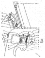
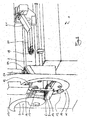
- a device 1 shown in FIGS. 1 to 4 for cutting foodstuffs in the form of a Gutsstrang in slices each, has an insertion area 2, in which a Gutsstrang of the food can be inserted.
- a footprint 3 of the Einlegel Schemes 2 is formed by the upper run of a circulating conveyor belt 4, the deflection and drive rollers for the sake of simplicity are not shown.
- the footprint 3 of the insertion region is further formed by a plurality of parallel to each other and between each a distance transversely to randomlynchtung having having straps 5 an additional feed means 6.
- the additional feed means 6 further comprises a roller provided on its outer casing with spikes (see in particular FIG. 1).
- the spikes run in circumferential rows, which are axially spaced apart in such a way that between each two adjacent straps 5 a number of spikes 7 of the roller is arranged.
- the spines 7 are dimensioned in their length so that they protrude with respect to the plane formed by the straps 5 as part of the footprint 3 and in this way can penetrate into the Gutsstrang guided along the footprint 3, to form a slip-preventing positive engagement.
- the device 1 further includes a cutting device 8, which comprises a rotationally drivable sickle-shaped knife 9.
- Component of the device 1 is further a scanning device 10 with a rotatably mounted scanning ring 11, which is provided with two offset by 180 ° arranged laser optical scanning elements 12, within a scan plane passing through a passage cross section within the scan ring Gutsstrang in terms of its outer contour, ie his Cross-section, scan and measure.
- the scan ring 11 in each case performs an oscillating rotational movement over an angular range of slightly more than 180 °, whereby due to the two scanning elements 12, the entire outer circumference of the Gutsstrangs is scanned within the scan plane.
- the hold-down device 13 consists of a rotatably mounted roller-shaped pressing element 15, from whose two front ends two vertically extending lifting rods 16 go out.
- the lifting rods 16 terminate in a drive means 17 of the hold-down device 13.
- the drive means not shown, there is a servo motor, which allows a fast and precise vertical displacement of the two lifting rods 16 and thus also the pressing member 15.
- the contact pressure element 15 is cylindrical in its central region, while adjoining the conical regions on both sides so that in cross-section in particular concave Gutstrnature are also guided laterally.
- the contact pressure element 15 can be designed as a rotatably driven and also provided with spikes roller.
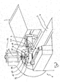
- the device 1 by far comprises a gripper device 18, which is provided at its the cutting device 8 facing the front end with an engaging element 19 in the form of 5 angled and parallel claws.
- the claws are rigidly connected to a front horizontally oriented part 20 of the gripping device 18.
- a rear obliquely upwardly extending portion 21 connects.
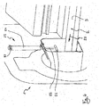
- the fixing device 22 which, viewed in the feed direction, is arranged in front of the scanning device 10.
- the fixing device 22 consists of a pivotably mounted in a joint 23 on a frame-shaped part of the machine housing arm 24, which is formed by a pneumatic cylinder.
- the downward emerging from the pneumatic cylinder piston rod 25 carries at its lower end a contact element 26 in the form of a horizontally extending rod portion which is rigidly connected to the piston rod 25 and this gives a T-shaped configuration at its end.
- the position of the contact element 26 is on the one hand by retraction or extension of the piston rod 25 variable.
- the contact element 26, starting from the first working position shown in FIGS. 3 and 4 in the feed direction (arrow 27 in FIG. 4), can be pivoted by rotation in the joint 23.
- the structure of the fixing device 22 will be explained in more detail later with reference to FIGS. 7 and 8.
- the rear part 21 of the gripper device 18 is fastened to a horizontally extending bar 29 by means of two clamping elements 28.
- the rod 29 is provided at its not visible in Figures 5 and 6 front end with a nut which cooperates with a lifting spindle 30.
- the lifting spindle 30 is over by a drive 31, which may be pneumatically or electrically actuated over set a non-visible belt drive in rotation, so that the rod 29 and with her the kind of boom forming parts 20 and 21 with the attached thereto engagement member 19 in the vertical direction and move up.
- the rod 29 entlag a the vertical stroke up and down limiting slot 32 in a housing 33 of the gripper device 18.
- the gripper device 18 is supported by means of an angled boom 34 via a slide bushing 35 on a linearly extending guide rod 36 from.
- the housing 33 of which also extends the extension arm 34 is mounted in a linearly displaceable manner on a further guide device.
- the linear displacement of the gripper device 18 overall takes place by means of an unrecognizable but generally known drive.
- the front part 20 below the engagement element 19 has an articulated stripping element 37 in the form of a comb, which is able to grip with its four prongs between the claws of the engagement element 19.
- the stripping element 37 is drivable via a lever mechanism and a pneumatic cylinder 38 not shown in detail such that it performs a pivoting movement about an axis of rotation, not shown, and pressed by an engagement position, not shown, in which the stripping element through the Gutsstrang upon penetration of the engagement element 19 upwards 6 can be converted into the stripping position shown in FIG. 6, in which the prongs of the stripping element 37 are located at a level below the tips of the claws of the engagement element 19.
- a still remaining piece connected with the engagement element which can not be further cut, can thereby be removed from the engagement element 19.
- FIG. 7 shows the fixing device 22 in a first working position, in which the contact element 26 located at the end of the piston rod 25 is in contact with the surface of a Gutsstrang located underneath but not shown at a first time.
- the piston rod 25 penetrates a first upper plate 39 in a first slot 40.
- a second plate 41 arranged underneath has a second slot 42 which extends in its projection into the contact surface 3 of the insertion region 2 in the direction of the feed direction 27.
- the two sheets 39 and 41 are pivotable relative to each other and that within a plane formed by their contact surfaces.
- Figure 8 shows the arm 24 together with the piston rod 25 in a second working position in which a pivoting has taken place by an angle ⁇ .
- a pivoting is due to the fact that the contact element 26 moves during the exercise of the fixing function in the feed direction (arrow 17), so that the contact point of the contact element 26 on the surface of the Gutsstrangs during the contact pressure corresponding to the feed rate of the Gutsstrangs by a certain distance in Feed direction has moved.
- This second working position penetrates the piston rod 25, the two slots 40 and 42 at their opposite to Figure 7 opposite end portions.
- the piston rod 25 penetrates the two sheets 39 and 41 always in a minimized in area passage cross-section to prevent the passage of dirt from the loading area upwards.
- the attachment of the plates 39 and 41 is carried out on a machine-fixed inclined plate 44, the inclination of the inclined rear portion 21 of the gripper device corresponds to the gripper device 18 can move sufficiently far forward.
- An unillustrated Gutsstrang a food, such as a raw ham with greatly varying cross-sectional shape is inserted into the insertion area 2.
- the gripper device 18 is positioned in the horizontal direction and in the vertical direction so that the claws of the engagement element 19 are located above the rear end region of the Gutsstrangs in the feed direction.
- the gripper device 18 is then lowered in the vertical direction, so that the engagement element 19 penetrates into the Gutsstrang.
- the conveyor 4 is continuously driven during the above-described operation.
- the positioning and lowering of the engagement member 19 of the gripper means 18 must therefore be done with moving Gutsstrang, i. during lowering, the gripper device 18 is moved simultaneously with the feed speed in the feed direction. A relative movement between the gripper device 18 and Gutsstrang thus does not take place.
- the Gutsstrang is held down at its front end during lowering of the engaging member 19 by means of the fixing device 22 and thus secured against tilting
- the pneumatic cylinder forming the arm 24 at the time of lowering the engaging member 19 is pressurized, so that the piston rod 25th extends and the contact element 26 is supported on the upper side of the Gutsstrangs in the front end region. Since the Gutsstrang moves during this holding or securing operation in the feed direction, and the contact element 26 must be able to follow this horizontal movement.
- the articulated mounting of the arm 24 including the piston rod 25 and the contact element 26 allows at this moment that the contact element 26 can follow the feed movement of Gutsstrangs.
- the cross section of Gutsstrangs is continuously detected within the scan plane in order to draw conclusions about the subsequently cut slices can.
- the information about the cross section of the Gutsstrangs determined by the scanning device according to the invention not only used to determine the weight of the cut slices, but also for positioning of the pressing member 15 of Niederhaltereiririchtaug 13.
- the information regarding the height of the respective cross section of Gutsstrangs is needed , If necessary, however, further information about the cross-sectional shape can also be incorporated into the determination of the optimum distance of the contact pressure element 15 of the hold-down device 13 from the contact surface 3.
- the gripper device 18 is then returned at maximum speed against the feed direction and at the same time raised.
- the next Gutsstrang has been placed on the conveyor belt 4, which is already taken in the already described at the beginning of the engagement member 19 of the gripper device 18 at its rear end.
- the fixing device 22 is back in action.
- the conveyor 4 was moved at a continuous speed, namely, the feed speed.
- the gutstrings are placed on the conveyor belt 4 side so that there is a sufficient horizontal distance between them.
Abstract
Description
Die Erfindung betrifft ein Verfahren zum Schneiden eines strangförmigen Lebensmittels, wobei ein Gutsstrang des Lebensmittels in einen Einlegbereich einer Schneidemaschine eingelegt wird, ein Eingriffselement einer Greifereinrichtung formschlüssig mit einem in Vorschubrichtung hinteren Ende des Gutsstrangs in Eingriff gebracht wird und anschließend der Gutsstrang mit der Greifereinrichtung fortlaufend auf eine Schneideinrichtung zu vorgeschoben und dort aufgeschnitten wird, wobei der Gutstrang während des Schneidvorgangs mittels einer Niederhaltereinrichtung in Richtung auf eine Aufstandsfläche des Einlegebereichs gepresst wird.The invention relates to a method for cutting a strand-shaped food, wherein a Gutsstrang of the food is inserted into an insertion region of a cutting machine, an engagement element of a gripper device is positively engaged with a rear end of the Gutsstrangs in the feed direction and then the Gutsstrang with the gripper device continuously on a cutting device is advanced and cut there, wherein the Gutstrang is pressed during the cutting operation by means of a hold-down device in the direction of a footprint of the insertion region.
Des weiteren betrifft die Erfindung eine Vorrichtung zum Schneiden eines strangförmigen Lebensmittels, mit der das vorstehend genannte Verfahren ausführbar ist.Furthermore, the invention relates to a device for cutting a strand-shaped food, with the above-mentioned method is executable.
Die Verwendung von Greifereinrichtungen zur sicheren Fixierung des Gutsstrangs während des Vorschub- und Schneidevorgangs ist allgemein bekannt. Üblich sind dabei sowohl Greifereinrichtungen mit klauen- oder krallenförmigen Eingriffselementen, die von einer Ruheposition in eine Eingriffsposition geschwenkt werden, aber auch solche, bei denen das Eingriffselement, das in diesem Fall auch innerhalb einer Ebene angeordnete Zinken aufweisen kann, in lineare Richtung in den Gutsstrang eingeführt wird. Während des; Vorschubs des Gutsstrangs auf die Schneideinrichtung zu und des sukzessiven Abschneidens von beispielsweise Scheiben verbleiben die Eingriffselemente innerhalb des Gutsstrangs. Kurz bevor das Eingriffselement in den Einflussbereich der Schneideinrichtung gelangen würde, wird der Schneidvorgang unterbrochen und das vom Eingriffselement noch festgehaltene Reststück des Gutsstrangs gelöst. Nach einem Rückfahren der Greifereinrichtung kann das Eingriffselement sodann erneut mit dem hinteren Ende eines nächsten Gutsstrangs in Eingriff gebracht werden.The use of gripper means for secure fixation of the Gutsstrangs during the feed and cutting operation is well known. Both gripper devices with claw- or claw-shaped engagement elements, which are pivoted from a rest position into an engagement position, but also those in which the engagement element, which in this case may also have tines arranged within a plane, are conventional in the Gutsstrang in a linear direction is introduced. During the; Feed of the Gutsstrangs on the cutting device and the successive cutting of, for example discs remain the engagement elements within the Gutsstrangs. Shortly before the engagement element would enter the sphere of influence of the cutting device, the cutting process is interrupted and the rest of the Gutsstrangs still held by the engagement element dissolved. After a return movement of the gripper device, the engagement element can then again be brought into engagement with the rear end of a next Gutsstrangs.
Insbesondere bei unregelmäßig geformten Gutsträngen eines harten Lebensmittels, wie beispielsweise Rohschinken, tritt es bei den bekannten Verfahren als nachteilig in Erscheinung, dass in dem Moment, in dem das Eingriffselement in den Gutsstrang eindringt, dieser von der Aufstandsfläche in den Einlagebereich abhebt. Insbesondere wenn sich zwischen dem hinteren Ende des Gutsstrangs und der Aufstandsfläche - durch die Form des Gutsstrangs bedingt - ein Freiraum befindet, wird aufgrund der großen Kräfte, die sich dem Eindringen des Eingriffselements entgegen setzen, das hintere Ende des Gutsstrangs herunter gedrückt, wodurch es im vorderen Bereich des Gutsstrangs zu einem Abheben kommt. Ein derartiger Vorgang ist Unerwünscht, da er zu dauerhaft instabilen Verhältnissen während des Vorschubs und des Aufscbneidens eines derartig fixierten Gutsstrangs kommt.Particularly in the case of irregularly shaped product strands of a hard food, such as raw ham, it is disadvantageous in the known methods that, at the moment in which the engaging element enters the Gutsstrang, this lifts from the footprint in the deposit area. In particular, if between the rear end of the Gutsstrangs and the footprint - due to the shape of Gutsstrangs - a space is due to the large forces that oppose the penetration of the engaging member, the rear end of the Gutsstrangs pressed down it comes in the front of the Gutsstrangs to lift off. Such a process is undesirable because it leads to permanently unstable conditions during the feed and the Aufbbneidens such a fixed Gutsstrangs.
Der Erfindung liegt die Aufgabe zugrunde, ein Verfahren und eine Vorrichtung zum Schneiden eines strangförmigen Lebensmittels vorzuschlagen, bei dem bzw. bei der ein Verkippen des Gutsstrangs beim Vorgang des Eindringens des Eingriffselements der Greifereinrichtung vermieden wird, um nach dem Eindringen des Eingriffselements eine für den anschließenden Vorschub und Schneidvorgang brauchbare Fixierung des Gutsstrangs zu erhalten.The invention has for its object to provide a method and apparatus for cutting a rope-shaped food, in which or in which a tilting of the Gutsstrangs in the process of penetration of the engagement member of the gripper device is avoided to after the penetration of the engagement member one for the subsequent Feed and cutting operation to obtain useful fixation of Gutsstrangs.
Ausgehend von dem Verfahren der eingangsbeschriebenen Art wird diese Aufgabe erfindungsgemäß dadurch gelöst, dass der Gutsstrang während des Eindringens des Eingriffselements in den Gutsstrang mit einer Fixiereinrichtung gegen Verkippen gesichert wird.Based on the method of the type described above, this object is achieved in that the Gutsstrang is secured during the penetration of the engaging element in the Gutsstrang with a fixing device against tilting.
Bei der Fixiereinrichtung handelt es sich um eine zu der Greifereinrichtung und zu der Niederhaltereinrichtung zusätzliche Einrichtung, mit der zusammen mit der Greifereinrichtung eine Halterung des Gutsstrangs zumindest an zwei unterschiedlichen Orten erfolgt. Der Angriffspunkt der Fixiereinrichtung und der Eingnffsort des Eingriffselements der Greifereinrichtung sind dabei so zu positionieren, dass ein Verkippen des Gutsstrangs verhindert wird. Insbesondere kann der Gutsstrang beidseitig eines typischerweise mittleren Auflagebereichs gehalten werden, damit Momente unterschiedlichen Drehsinns in den Gutsstrang eingeleitet werden können und sich optimalerweise gegeneinander aufheben. Aber auch eine Abstützung des Gutsstrangs auf dessen Unterseite durch die Fixiereinrichtung ist zur Kompensation der von dem Eingriffselement ausgeübten Kräfte prinzipiell denkbar. Während somit die Fixiereinrichtung zumindest während des Eindringens des Eingriffselements der Greifereinrichtung sichernd aktiv ist, erfolgt die anpressende Wirkung der an sich bekannten, unabhängig von der Fixiereinrichtung steuer- und bewegbaren Niederhaltereinxichtung typischerweise - zeitlich und räumlich - später, da die Niederhaltereinrichtung meist erst in kurzem Abstand vor der Schneideinrichtung angeordnet ist. Eine Überschneidung der aktiven Phasen von Fixiereinrichtung und Niederhaltereinrichtung ist aber nicht ausgeschlossen.The fixing device is an additional device to the gripper device and to the hold-down device, with which the goods strand is held together with the gripper device at least at two different locations. The point of attack of the fixing device and the Einnffsort the engagement element of the gripper device are to be positioned so that a tilting of Gutsstrangs is prevented. In particular, the Gutsstrang can be kept on both sides of a typically central bearing area so that moments of different rotational direction can be introduced into the Gutsstrang and optimally cancel each other. But also a support of Gutsstrangs on the underside by the fixing device is in principle conceivable to compensate for the forces exerted by the engagement element forces. Thus, while the fixing device is at least during the penetration of the engagement element of the gripping device sicherd actively, the pressing effect of the known, independent of the fixing taxable and movable Niederhalteereinxichtung typically - temporally and spatially - later, since the hold-down device usually only at a short distance is arranged in front of the cutting device. However, an overlap of the active phases of fixing device and hold-down device is not excluded.
Dadurch dass gemäß der Erfindung der Gutsstrang auch in dem Moment, in dem das Eingriffselement in den Gutsstrang eintritt, an einer ungewollten und üblicherweise unkontrollierten Bewegung gehindert wird, liegt der Gutsstrang stets in einem gesicherten Zustand vor, der sogleich die Einleitung der weiteren zu dem Schneidverfrahren zählenden Verfahrensschritte erlaubt, wie beispielsweise der kontrollierten und von Querbewegungen freien Durchführung des Gutsstrangs durch eine Scaneinrichtung und das anschließende Aufschneiden. Ohne die erfindungsgemäße Fixiereinrichtung bestünde die Gefahr, dass der Gutsstrang unter der Wirkung einer auch bereits bei bekannten Maschinen vorhandenen Niederhaltereinrichtung, die meist zwischen der Scaneinrichtung und der Schneideinrichtung angeordnet ist, in Querrichtung zur Vorschubrichtung, d.h. insbesondere auf die Aufstandsfläche des Einlegebereichs zu, verlagert wird, wodurch das Messergebnis der Scaneinrichtung und somit die Gewichtsgenauigkeit der abgeschnittenen Scheiben negativ beeinflusst wird.Characterized that according to the invention, the Gutsstrang is hindered in an unwanted and usually uncontrolled movement even in the moment in which the engagement element enters the Gutsstrang, the Gutsstrang is always in a secure state, which immediately initiate the other to the Schneidverfrahren counting process steps allowed, such as the controlled and free movement of the Gutsstrangs by a scanning device and the subsequent slicing. Without the fixing device according to the invention, there would be a risk that the Gutsstrang under the action of existing even in known machines holding device, which is usually located between the scanning device and the cutter, in the transverse direction to the feed direction, ie in particular on the footprint of the loading area, is displaced , whereby the measurement result of the scanning device and thus the weight accuracy of the cut slices is adversely affected.
Gemäß einer Ausgestaltung des erfindungsgemäßen Verfahrens wird vorgeschlagen, dass das Sichern des Gutsstrangs gegen Verkippen mittels der Fixiereinrichtung im wesentlichen nur während des Eindringens des Exngriffselements der Greifereinrichtung erfolgt. Spätestens zu einem Zeitpunkt, in dem sich ein vorderes Ende des Gutsstrangs im Einflussbereich des vor der Schneideinrichtung angeordneten Niederhalters befindet, ist eine Kraftwirkung der Fixiereinrichtung nicht mehr erforderlich. Die Fixiereizuriehtung kann dann in ihrer deaktivierten Form während des weiteren Vorschubs des Gutsstrangs den für die Durchfahrt der Greifereinrichtung erforderlichen Freiraum im Bereich des Förderquerschnitts schaffen.According to one embodiment of the method according to the invention, it is proposed that the securing of the Gutsstrangs against tilting by means of the fixing device takes place substantially only during the penetration of the Exngriffselements the gripper device. At the latest at a time when a front end of the Gutsstrangs is in the sphere of influence of the arranged in front of the cutter hold-down, a force effect of the fixing is no longer required. The Fixiereizuriehtung can then create in their deactivated form during the further feed of the Gutsstrangs required for the passage of the gripper device free space in the region of the conveyor cross-section.
Die Erfindung weiter ausgestaltend ist vorgesehen, dass das Sichern des Gutsstrangs gegen Verkippen durch Fixieren an dem dem Eingriffselement der Greifereinrichtung gegenüberliegenden Ende erfolgt. Da sich der Auflagebereich des Gutsstrangs in der Regel in dessen Mitte befindet, wird auf diese Weise die Einleitung entgegengesetzter Drehmomente um einen möglichen Drehpunkt erzielt und somit der Gutsstrang an beiden Seiten niedergehalten, ohne dass er sich ungewollt verdrehen könnte.The invention further ausgestaltend is provided that the securing of the Gutsstrangs against tilting by fixing takes place at the opposite end of the engagement element of the gripper device. Since the contact area of Gutsstrangs is usually in the middle, in this way the introduction of opposite torques is achieved by a possible pivot point and thus the Gutsstrang held down on both sides, without that he could turn unintentionally.
Wenn der Gutsstrang während des Eindringens des Eingriffselements der Greifereinrichtung und des Fixierens mittels der Fixiereinrichtung auf die Schneideinrichtung vorgeschoben wird und die Greifereinrichtung und zu mindestens ein mit der Oberfläche des Gutsstrangs in Kontakt stehendes Kontaktelement der Fixiereinrichtung mit der selben Geschwindigkeit auf die Schneidebene zu bewegt werden, kann der Vorschub des Gutsstrangs auch im Moment des Aktivierens der Greifeinrichtung und der Fixiereinrichtung ohne Unterbrechung fortgesetzt werden. Dies ist wichtig, bei sogenannten kontinuierlichen Schneidverfahren, bei denen der Gutsstrang ohne Stillstand aus dem Einlegebereich auf die Schneideinrichtung zu, vorgeschoben werden.When the Gutsstrang is advanced during penetration of the engagement element of the gripper device and the fixing by means of the fixing device on the cutting device and the gripper device and at least one standing with the surface of the Gutsstrangs contact element of the fixing device at the same speed to the cutting plane to move the feed of the Gutsstrangs can be continued without interruption in the moment of activating the gripping device and the fixing device. This is important in so-called continuous cutting processes, in which the Gutsstrang without standstill from the loading area on the cutting device, are advanced.
Auf einfache Weise lässt sich eine Beweglichkeit des Kontaktelements der Fixiereinrichtung realisieren, wenn dieses an einem Arm der Fixiereinrichtung befestigt ist und dieser Arm während des Eindringens der Eingriffselemente der Greifereinrichtung in Vorschubrichtung schwenkbar ist.In a simple manner, a mobility of the contact element of the fixing device can be realized if it is attached to an arm of the fixing device and this arm is pivotable in the feed direction during the penetration of the engagement elements of the gripper device.
Um während des vorgenannten Schwenkvorgangs kontinuierlich eine Kraftwirkung auf den nieder zu haltenden Gutsstrang ausüben zu können, ist vorgesehen, die Länge des Arms der Fixiereinrichtung während der Schwenkbewegung so zu verlängern, dass das Kontaktelement stets in Kontakt mit der Oberfläche des Gutsstrangs bleibt. Für die Verlängerung des Arms wird vorzugsweise ein Pneumatikzylinder verwendetIn order to continuously exert a force on the Gutsstrang to be held down during the aforementioned pivoting operation, it is provided to extend the length of the arm of the fixing device during the pivoting movement so that the contact element always remains in contact with the surface of the Gutsstrangs. For the extension of the arm, a pneumatic cylinder is preferably used
Verfahrensmäßig besteht eine Weiterbildung des Verfahrens außerdem darin, dass das Kontaktelement der Fixiereinrichtung mindestens so lange in Kontakt mit der Oberfläche des Gutsstrangs bleibt, bis ein Anpresselement der Niederhaltereinrichtung mit der Oberfläche des Gutsstrangs in abstützenden Kontakt gelangt ist. Hierdurch wird der Gutsstrang nach Eindringen des Eingriffselements fortlaufend niedergehalten, zunächst nur durch die Fixiereinrichtung, dann während einer Übergangsphase zusätzlich auch durch die Niederhaltereinrichtung und schließlich allein durch die Niederhaltereinrichtung. Eine ungewollte Bewegung beim Abheben des Kontaktelements der Fixiereinrichtung kann so sicher vermieden werden.According to a further development of the method, the contact element of the fixing device remains in contact with the surface of the Gutsstrangs at least until a pressing element of the retaining device has come into supporting contact with the surface of the Gutsstrangs. As a result, the Gutsstrang is continuously held down after penetration of the engagement element, initially only by the fixing device, then during a transitional phase in addition by the hold-down device and finally only by the hold-down device. An unwanted movement when lifting the contact element of the fixing can be safely avoided.
Des weiteren ist nach der Erfindung noch vorgesehen, dass das Kontaktelement der Fixiereinrichtung nach Beendigung des Sicherns des Gutsstrangs gegen Verkippen aus einer Arbeitsstellung in eine Ruhestellung zurückbewegt wird, in der die Greifereinrichtung zwischen dem Kontaktelement und einer Aufstandsfläche des Einlegebereichs hindurch bewegt werden kann.Furthermore, it is provided according to the invention that the contact element of the fixing device after completion of securing the Gutsstrangs against tilting from a working position is moved back into a rest position in which the gripper device between the contact element and a footprint of the loading area can be moved through.
In vorrichtungsmäßiger Hinsicht wird die zugrunde liegende Aufgabe gelöst durch eine Vorrichtung zum Schneiden eines strangförmigen Lebensmittels mit einem Einlegebereich, in den ein Gutsstrang des Lebensmittels einlegbar ist, einer Schneideinrichtung und einer Greifereinrichtung, die ein Eingriffselement aufweist, das in ein in Vorschubrichtung des Gutsstrangs hinteres Ende des Gutsstrangs einführbar ist, wobei der Gutsstrang mit der Greifereinrichtung entlang einer Aufstandsfläche des Einlegebereichs auf die Schneideinrichtung zu verschiebbar und mittels einer Niederhaltereinrichtung während des Schneidvorgang in Richtung auf die Aufstandsfläche pressbar ist und die dadurch gekennzeichnet ist, dass der Gutsstrang während des Eindringens des Eingriffselements der Greifereinrichtung mittels einer Fixiereinrichtung gegen Verkippen sicherbar ist.In terms of the device, the underlying object is achieved by a device for cutting a strand-shaped food with a loading area in which a Gutsstrang of the food is inserted, a cutting device and a gripper device having an engagement element, which in a feed direction of Gutsstrangs rear end the Gutsstrangs is insertable, wherein the Gutsstrang with the gripper device along a contact surface of the loading area on the cutting device to be displaced and pressed by means of a hold-down device during the cutting process in the direction of the contact surface and which is characterized in that the Gutsstrang during penetration of the engagement element of Gripper device can be secured against tilting by means of a fixing device.
Mit einer derartigen Vorrichtung lässt sich das Problem der ungewollten und unkontrollierbaren Verdrehung eines Gutsstrangs, insbesondere eines harten Lebensmittels wie Rohschinken, sicher vermeiden, da die als Zusatzeinrichtung vorgesehene Fixiereinrichtung an einem zweiten Ort ein Sichern des Gutsstrangs erlaubt.With such a device, the problem of unwanted and uncontrollable rotation of a Gutsstrangs, in particular a hard food such as raw ham, safely avoid, as provided as an additional fixing allows a securement of the Gutsstrangs at a second location.
Gemäß einer bevorzugten Ausführungsform der erfindungsgemäßen Vorrichtung greift ein Kontaktelement der Fixiereinrichtung an dem Ende des Gutsstrangs an, das dem Ende gegenüber liegt, an dem das Eingriffselement der Greifereinrichtung eindringt. Durch die Abstützung an gegenüberliegenden Enden wird eine Drehbewegung des Gutsstrangs um eine Drehachse im Bereich einer mittleren Auflagefläche sicher verhindert.According to a preferred embodiment of the device according to the invention, a contact element of the fixing device engages at the end of the Gutsstrangs, opposite to the end is located at which the engagement element of the gripper device penetrates. Due to the support at opposite ends, a rotational movement of the Gutsstrangs around a rotation axis in the region of a central bearing surface is reliably prevented.
Ferner ist vorgesehen, dass ein Kontaktelement der Fixiereinrichtung während des Sicherns gegen Verkippen mit den sich in Vorschubrichtung bewegenden Gutsstrangs bewegbar ist. Hiermit wird der typischen Verfahrensweise entsprochen, gemäß der das Eindringen des Eingriffselements bei fortgesetzter Vorschubbewegung des Gutsstrangs erfolgt. Um auf einfache Weise die Funktion einer Abstützung des sich bewegenden Gutsstrangs erfüllen zu können, kann das Kontaktelement der Fixiereinrichtung pendelnd an einem Arm aufgehängt sein, dessen Länge mittels eines Fluidzylinders vorzugsweise eines Pneumatikzylinders veränderlich ist.It is further provided that a contact element of the fixing device during securing against tilting with the Gutsstrangs moving in the feed direction is movable. This complies with the typical procedure according to which the penetration of the engagement element takes place with continued feed movement of the Gutsstrangs. In order to be able to fulfill in a simple manner the function of supporting the moving Gutsstrangs, the contact element of the fixing device can be suspended pendulously on an arm whose length is variable by means of a fluid cylinder, preferably a pneumatic cylinder.
Eine Ausgestaltung der Erfindung besteht außerdem noch darin, dass der Fluidzylinder während des Sicherns gegen Verkippen mit einem konstanten Druck des Arbeitsfluids beaufschlagt wird und dabei mit fortgesetzter Bewegung des Gutsstrangs fortlaufend seine Kolbenstange ausfährt, um das daran endseitig befestigte Kontaktelement mit der Oberfläche des Gutsstrangs stets in Kontakt zu halten. Vorzugsweise ist der Fluidzylinder in einer Ruhestellung, in der das Kontaktelement außer Kontakt mit der Oberfläche des Gutsstrangs ist, vertikal ausgerichtet und wird in Arbeitsstellung mit der Bewegung des Gutsstrangs auf die Schneideinrichtung zu entsprechend ausgelenkt.An embodiment of the invention also consists in the fact that the fluid cylinder is acted upon during backup against tilting with a constant pressure of the working fluid and thereby continuously extended with continued movement of Gutsstrangs piston rod to the end attached thereto contact element with the surface of Gutsstrangs always in To keep in contact. Preferably, the fluid cylinder is in a rest position, in which the contact element is out of contact with the surface of the Gutsstrangs, vertically aligned and is deflected in working position with the movement of the Gutsstrangs on the cutter to corresponding.
Schließlich ist noch vorgesehen, dass die Kolbenstange des Fluidzylinders durch ein erstes Blech mit einem Langloch geführt ist, dessen Breite der Breite der Kolbenstange angepasst ist und deren Projektion in die Aufstandsfläche des Einlegebereichs parallel zu der Vorschubrichtung verläuft und durch ein parallel zu dem ersten und innerhalb einer mit diesem gemeinsamen Ebene drehbar gelagertes zweites Blech geführt ist, das ebenfalls einer in seiner Breite der Kolbenstange angepasstes Langloch aufweist. Auf diese Weise wird trotz der Schwenkbewegung der Kolbenstange des Fluidzylinders der Durchbruch zwischen dem Förderquerschnitt und dem darüber befindlichen Maschinenraum auf ein Minimum, nämlich die sich überlappenden Abschnitte der beiden Langlöcher, begrenzt. Die Gefahr, dass unerwünschte Stoffe in das Innere des Maschinengehäuses eindringen, wird hierdurch minimiert.Finally, it is provided that the piston rod of the fluid cylinder is guided through a first plate with a slot whose width is adapted to the width of the piston rod and whose projection into the contact surface of the insertion region parallel to the feed direction and by a parallel to the first and within a rotatably mounted with this common plane second plate is guided, which also has a matched in its width of the piston rod slot. In this way, despite the pivotal movement of the piston rod of the fluid cylinder of the breakthrough between the conveyor section and the engine room located above it to a minimum, namely the overlapping portions of the two slots limited. The risk that undesirable substances penetrate into the interior of the machine housing is thereby minimized.
Die Erfindung wird nachfolgend anhand eines Ausführungsbeispiels einer Vorrichtung zum Schneiden von Lebensmitteln, die in der Zeichnung dargestellt ist, näher erläutert. Es zeigt:
- Figur 1
- eine perspektivische Ansicht einer Schneidmaschine unter einem Blickwinkel schräg entgegen der Vorschubrichtung,
Figur 2- wie Figur 1, jedoch in einer anderen Perspektive und einer etwas vergrößerten Darstellung,
Figur 3- eine perspektivische Ansicht der Schneidmaschine unter einem Blickwinkel schräg in Vorschubrichtung,
Figur 4- wie
Figur 3, jedoch in einer anderen Perspektive und in etwas vergrößerter Darstellung, Figur 5- eine perspektivische Ansicht der Greifereinrichtung,
Figur 6- wie
Figur 5, jedoch in einer anderen Perspektive, Figur 7- eine perspektivische Ansicht der Fixiereinrichtung in einer ersten Arbeitsstellung und
- Figur 8
wie Figur 7, jedoch in einer zweiten Arbeitsstellung.
- FIG. 1
- a perspective view of a cutting machine at an angle obliquely against the feed direction,
- FIG. 2
- like Figure 1, but in a different perspective and a slightly enlarged view,
- FIG. 3
- a perspective view of the cutting machine at an angle obliquely in the feed direction,
- FIG. 4
- as in FIG. 3, but in a different perspective and in a slightly enlarged representation,
- FIG. 5
- a perspective view of the gripper device,
- FIG. 6
- like Figure 5, but in a different perspective,
- FIG. 7
- a perspective view of the fixing device in a first working position and
- FIG. 8
- like Figure 7, but in a second working position.
Eine in den Figuren 1 bis 4 dargestellte Vorrichtung 1 zum Schneiden von Lebensmitteln in Form jeweils eines Gutsstrangs in Scheiben, weist einen Einlegebereich 2 auf, in den ein Gutsstrang des Lebensmittels eingelegt werden kann. Eine Aufstandsfläche 3 des Einlegelbereichs 2 wird von dem Obertrum eines umlaufenden Förderbandes 4 gebildet, dessen Umlenk-und Antriebsrollen der Einfachheit halber nicht dargestellt sind. Die Aufstandsfläche 3 des Einlegebereichs wird des weiteren von einer Mehrzahl von parallel zueinander verlaufenden und zwischen sich jeweils einen Abstand quer zur Fördernchtung aufweisenden Riemchen 5 eines Zusatzvorschubmittels 6 gebildet. Das Zusatzvorschubmittel 6 umfasst des weiteren eine an ihrem Außenmantel mit Stacheln (siehe insbesondere Fig.1) versehenen Walze. Die Stacheln verlaufen in umlaufenden Reihen, die axial in der Weise zueinander beabstandet sind, dass jeweils zwischen zwei benachbarten Riemchen 5 eine Reihe von Stacheln 7 der Walze angeordnet ist. Die Stacheln 7 sind in ihrer Länge so bemessen, dass sie gegenüber der von den Riemchen 5 gebildeten Ebene als Teil der Aufstandsfläche 3 vorstehen und auf diese Weise in den entlang der Aufstandsfläche 3 geführten Gutsstrang eindringen können, um einen Schlupf verhindernden Formschluss zu bilden.A device 1 shown in FIGS. 1 to 4 for cutting foodstuffs in the form of a Gutsstrang in slices each, has an
Die Vorrichtung 1 enthält des weiteren eine Schneideinrichtung 8, die ein drehantreibbares sichelförmiges Messer 9 umfasst.The device 1 further includes a cutting device 8, which comprises a rotationally drivable sickle-shaped
Bestandteil der Vorrichtung 1 ist des weiteren eine Scaneinrichtung 10 mit einem drehantreibbar gelagerten Scanring 11, der mit zwei um 180° versetzt angeordneten laseroptischen Scanelementen 12 versehen ist, die innerhalb einer Scanebene den durch einen Durchtrittsquerschnitt innerhalb des Scanrings hindurchtretenden Gutsstrang hinsichtlich seiner Außenkontur, d.h. seines Querschnitts, abtasten und vermessen. Der Scanring 11 vollführt jeweils eine oszillierende Drehbewegung über einen Winkelbereich von etwas mehr als 180°, wodurch aufgrund der zwei Scanelemente 12 der gesamte Außenumfang des Gutsstrangs innerhalb der Scanebene abgetastet wird.Component of the device 1 is further a
Weiterer Bestandteil der Vorrichtung 1 ist eine Niederhaltereinrichtung 13, die zwischen der Scaneinrichtung 10 und einem Führungsrahmen 14 für das Messer 9 der Schneideinrichtung 8 angeordnet ist. Die Niederhaltereinrichtung 13 besteht aus einem drehbar gelagerten walzenförmigen Anpresselement 15, von dessen beiden stirnseitigen Enden zwei vertikal verlaufende Hubstangen 16 ausgehen. Die Hubstangen 16 enden in einer Antriebseinrichtung 17 der Niederhaltereinrichtung 13. In der nicht näher dargestellten Antriebseinrichtung befindet sich ein Servomotor, der eine schnelle und präzise vertikale Verschiebung der beiden Hubstangen 16 und damit auch des Anpresselements 15 gestattet. Das Anpresselement 15 ist in seinem Mittelbereich zylindrisch ausgeführt, während sich die beidseitig an den Mittelbereich kegelförmige Bereiche anschließen, so dass im Querschnitt insbesondere konkav ausgebildete Gutstränge auch seitlich geführt werden. Optional kann das Anpresselement 15 als drehantreibbare und ebenfalls mit Stacheln versehene Walze ausgeführt werden.Another component of the device 1 is a hold-down
Die Vorrichtung 1 umfasst des weitem eine Greifereinrichtung 18, die an ihrem der Schneideinrichtung 8 zugewandten vorderen Ende mit einem Eingriffselement 19 in Form von 5 abgewinkelten und parallel zueinander verlaufenden Krallen versehen ist. Die Krallen sind starr mit einem vorderen horizontal ausgerichteten Teil 20 der Greifereinrichtung 18 verbunden. An dieses Teil 20 schließt sich ein hinteres schräg nach oben verlaufendes Teil 21 an. Der Aufbau der in vertikale Richtung auf- und abbewegbaren Greifereinrichtung 18 wird anhand der Figuren 5 und 6 noch weiter unten noch genauer erläutert.The device 1 by far comprises a gripper device 18, which is provided at its the cutting device 8 facing the front end with an engaging
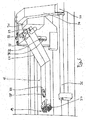
Ein weiterer Bestandteil der Vorrichtung 1 wird von einer Fixiereinrichtung 22 gebildet, die in Vorschubrichtung betrachtet vor der Scaneinrichtung 10 angeordnet ist. Die Fixiereinrichtung 22 besteht aus einem in einem Gelenk 23 schwenkbar an einem rahmenförmigen Teil des Maschinengehäuses gelagerten Arm 24, der von einem Pneumatikzylinder gebildet wird. Die nach unten aus dem Pneumatikzylinder austretende Kolbenstange 25 trägt an ihrem unteren Ende ein Kontaktelement 26 in Form eines horizontal verlaufenden Stangenabschnitts, der starr mit der Kolbenstange 25 verbunden ist und dieser an ihrem Ende eine T-förmige Gestalt verleiht. Die Position des Kontaktelements 26 ist einerseits durch Ein- oder Ausfahren der Kolbenstange 25 veränderlich. Des weiteren lässt sich das Kontaktelement 26, ausgehend von der in den Figuren 3 und 4 gezeigten ersten Arbeitsstellung in Vorschubrichtung (Pfeil 27 in Figur 4) durch Drehung in dem Gelenk 23 verschwenken. Der Aufbau der Fixiereinrichtung 22 wird anhand der Figuren 7 und 8 später nochmals näher erläutert.Another component of the device 1 is formed by a fixing
Mit Blick auf die Figuren 5 und 6 wird deutlich, dass der hintere Teil 21 der Greifereinrichtung 18 mithilfe von zwei Klemmelementen 28 an einer horizontal verlaufenden Stange 29 befestigt sind. Die Stange 29 ist an ihrem in den Figuren 5 und 6 nicht sichtbaren stirnseitigen Ende mit einer Mutter versehen, die mit einer Hubspindel 30 zusammen wirkt. Die Hubspindel 30 wird von einem Antrieb 31, der pneumatisch oder elektrisch betätigt sein kann, über einen nicht sichtbaren Riemenantrieb in Rotation versetzt, so dass sich die Stange 29 und mit ihr die eine art Ausleger bildenden Teile 20 und 21 mit dem daran angeschlossenem Eingriffselement 19 in vertikale Richtung auf und abbewegen. Dabei bewegt sich die Stange 29 entlag eines den Vertikalhub nach oben und unten begrenzenden Langlochs 32 in einem Gehäuse 33 der Greifereinrichtung 18. Die Greifereinrichtung 18 stützt sich mithilfe eines abgewinkelten Auslegers 34 über eine Gleitbuchse 35 an einer linear verlaufenden Führungsstange 36 ab. Auf der bezüglich des Einlegebereichs 2 gegenüberliegenden Seite der Greifereinrichtung 18 ist deren Gehäuse 33, von dem auch der Ausleger 34 ausgeht, linear verschieblich an einer weiteren Führungseinrichtung gelagert. Die lineare Verschiebung der Greifereinrichtung 18 insgesamt erfolgt mithilfe eines nicht erkennbaren, aber allgemein bekannten Antriebs.With reference to FIGS. 5 and 6, it is clear that the
Wie sich insbesondere aus Figur 6 ergibt, weist das vordere Teil 20 unterhalb des Eingriffselements 19 ein gelenkig gelagertes Abstreifelement 37 in Form eines Kamms auf, der mit seinen vier Zinken zwischen die Krallen des Eingriffselements 19 zu greifen vermag. Das Abstreifelement 37 ist über einen nicht näher gezeigten Hebelmechanismus und einen Pneumatikzylinder 38 derart antreibbar, dass es eine Schwenkbewegung um eine nicht gezeigte Drehachse ausführt und dabei von einer nicht dargestellten Eingriffsstellung, in der das Abstreifelement durch den Gutsstrang beim Eindringen des Eingriffselements 19 nach oben gedrückt ist, in die in Figur 6 gezeigte Abstreifstellung überführt werden kann, in der sich die Zinken des Abstreifelements 37 auf einer Höhe unterhalb der Spitzen der Klauen des Eingriffselements 19 befinden. Wie später noch näher erläutert wird, lässt sich hierdurch ein noch in mit dem Eingriffselement in Verbindung stehendes Reststück, dass nicht weiter aufgeschnitten werden kann von dem Eingriffselement 19 abstreifen.As can be seen in particular from FIG. 6, the
Figur 7 zeigt die Fixiereinrichtung 22 in einer ersten Arbeitsstellung, in der sich das am Ende der Kolbenstange 25 befindliche Kontaktelement 26 zu einem ersten Zeitpunkt in Kontakt mit der Oberfläche eines darunter befindlichen aber nicht dargestellten Gutsstrangs befindet. Die Kolbenstange 25 durchdringt ein erstes oberes Blech 39 in einem ersten Langloch 40. Ein darunter angeordnetes zweites Blech 41 besitzt ein zweites Langloch 42 das in seiner Projektion in die Aufstandsfläche 3 des Einlegebereichs 2 in Richtung der Vorschubrichtung 27 verläuft. Mithilfe einer Schraubenverbindung 43 sind die beiden Bleche 39 und 41 relativ zu einander schwenkbar und zwar innerhalb einer von ihren Kontaktflächen gebildeten Ebene.FIG. 7 shows the fixing
Figur 8 zeigt den Arm 24 samt der Kolbenstange 25 in einer zweiten Arbeitsstellung, in der eine Verschwenkung um einen Winkel α stattgefunden hat. Eine derartige Verschwenkung rührt daher, dass sich das Kontaktelement 26 während der Ausübung der Fixierfunktion in Vorschubrichtung (Pfeil 17) bewegt, so dass sich die Kontaktstelle des Kontaktelements 26 an der Oberfläche des Gutsstrangs während der Anpresszeit entsprechend der Vorschubgeschwindigkeit des Gutsstrangs um eine gewisse Strecke in Vorschubrichtung bewegt hat. In dieser zweiten Arbeitsposition durchdringt die Kolbenstange 25 die beiden Langlöcher 40 und 42 an ihren im Vergleich zur Figur 7 gegenüberliegenden Endbereichen. Durch die Verschwenkung des drehbeweglichen Blechs 39 gegenüber dem starren Blech 41, durchdringt die Kolbenstange 25 die beiden Bleche 39 und 41 stets in einem flächenmäßig minimierten Durchtrittsquerschnitt,um den Durchtritt von Verschmutzungen aus dem Einlegebereich nach oben zu vermeiden. Die Befestigung der Bleche 39 und 41 erfolgt an einem maschinenfesten geneigten Blech 44, dessen Neigung des geneigten hinteren Teils 21 der Greifereinrichtung entspricht, um die Greifereinrichtung 18 hinreichend weit nach vorne verfahren zu können.Figure 8 shows the
Ein nicht dargestellter Gutsstrang eines Lebensmittels, wie beispielsweise ein Rohschinken mit stark variierender Querschnittsform, wird in den Einlegebereich 2 eingelegt. Die Greifereinrichtung 18 wird in horizontale Richtung und in vertikale Richtung so positioniert, dass sich die Klauen des Eingriffselements 19 oberhalb des in Vorschubrichtung hinteren Endbereichs des Gutsstrangs befinden. Die Greifereinrichtung 18 wird sodann in vertikale Richtung abgesenkt, so dass das Eingriffselement 19 in den Gutsstrang eindringt.An unillustrated Gutsstrang a food, such as a raw ham with greatly varying cross-sectional shape is inserted into the
Da es sich bei der beschriebenen Vorrichtung 1 um eine kontinuierlich arbeitende Maschine handelt, wird das Förderband 4 während des vorstehend beschriebenen Vorgangs kontinuierlich angetrieben. Die Positionierung und Absenkung des Eingriffselements 19 der Greifereinrichtung 18 muss daher bei sich bewegendem Gutsstrang erfolgen, d.h. während des Absenkens wird die Greifereinrichtung 18 gleichzeitig mit der Vorschubgeschwindigkeit in Vorschubrichtung bewegt. Eine Relativbewegung zwischen Greifereinrichtung 18 und Gutsstrang findet somit nicht statt.Since the described apparatus 1 is a continuous machine, the
Erfindungsgemäß wird der Gutsstrang an seinem vorderen Ende während des Absenkens des Eingriffselements 19 mittels der Fixiereinrichtung 22 niedergehalten und somit gegen Verkippen gesichert Zu diesem Zweck wird der den Arm 24 bildende Pneumatikzylinder zum Zeitpunkt des Absenkens des Eingriffselements 19 mit Druck beaufschlagt, so dass die Kolbenstange 25 ausfährt und sich das Kontaktelement 26 auf der Oberseite des Gutsstrangs in dessen vorderen Endbereich abstützt. Da sich der Gutsstrang während dieses Halte- bzw. Sicherungsvorgangs in Vorschubrichtung bewegt, muss auch das Kontaktelement 26 dieser horizontalen Bewegung folgen können. Die gelenkige Lagerung des Arms 24 einschließlich der Kolbenstange 25 und des Kontaktelements 26 erlaubt in diesem Moment, dass das Kontakt element 26 der Vorschubbewegung des Gutsstrangs folgen kann. Die Anfangs- und Endposition der Schwenkbewegung sind in den Figuren 7 und 8 dargestellt. Damit die Fixiereinrichtung 22 auch in der in Figur 8 dargestellten zweiten Arbeitsposition ihre Haltefunktion ausüben kann, ist eine größere Länge des Armes 24 erforderlich, d.h. die Kolbenstange 25 muss weiter aus dem Pneumatikzylinder ausgefahren sein. Daher wird der Pneumatikzylinder während des Fixiervorgangs kontinuierlich mit der Druckversorgung verbunden und übt daher auch in seinem weiter ausgefahrenen Zustand gemäß Figur 8 eine (gleich große) Haltekraft auf die Oberfläche des Gutsstrangs aus. Die Endposition der Kolbenstange, d.h. des Kontaktelements 26, ergibt sich somit automatisch durch den vorgegebenen Systemdruck, der Druckluft. Unabhängig von der Schwenkposition der Fixiereinrichtung 22 sichert diese somit den Gutsstrang stets mit der selben Haltekraft.According to the Gutsstrang is held down at its front end during lowering of the engaging
Sobald das Eingriffselement 19 vollständig in das hintere Ende des Gutsstrangs eingedrungen ist und die Greifereinrichtung 18 kontinuierlich mit Vorschubgeschwindigkeit auf die Schneideinrichtung 8 zu bewegt wird, wird die Kolbenstange 25 der Fixiereinrichtung 22 durch Beaufschlagung der anderen Seite des Kolbens des Pneumatikzylinders aktiv weitest möglich wieder eingezogen. Während in den Figuren 3 und 4 die Kolbenstange 25 und das Kontaktelement 26 in einer ausgefahrenen Position, d.h. einer Fixicrstellung gezeigt sind, wird die Kolbenstange in einer Ruhestellung soweit wieder eingezogen, dass das Kontaktelement 26 unmittelbar an dem geneigten Blech 44 anliegt und damit einen geringst möglichen Raumbedarf hat.As soon as the
Während des Vorschubs des Gutsstrangs durch die Scaneinrichtung wird fortlaufend der Querschnitt des Gutsstrangs innerhalb der Scanebene erfasst, um daraus Rückschlüsse auf die nachfolgend abgeschnittenen Scheiben ziehen zu können. Die von der Scaneinrichtung ermittelten Informationen über den Querschnitt des Gutsstrangs werden erfindungsgemäß jedoch nicht nur zur Gewichtsbestimmung der abgeschnittenen Scheiben verwendet, sondern gleichfalls zur Positionierung des Anpresselements 15 der Niederhaltereiririchtaug 13. Zu diesem Zweck wird insbesondere die Information bezüglich der Höhe des jeweiligen Querschnitts des Gutsstrangs benötigt. Bedarfsweise können aber auch weitere Informationen über die Querschnittsform mit in die Bestimmung des optimalen Abstandes des Anpresselements 15 der Niederhalteeinrichtung 13 von der Aufstandfläche 3 einfließen. Da die Querschnittsvermessung mittels der Scaneinrichtung 10 zeitlich kurz vor dem Passieren der Niederhaltereinrichtung 13 erfolgt, verbleibt genügend Zeit, um die ermittelten Querschnittsinformationen in eine stets optimale Positionierung des Anpresselements 15 umzusetzen. Bei Verwendung eines selbsthemmenden Antriebs für die Hubstangen 16 des Anpresselements 15, ist das Anpresselement 15 praktisch nicht in vertikale Richtung nachgiebig. Mit der erfindungsgemäß durch die Scaneinrichtung 10 gesteuerten Niederhaltereinrichtung 13 lassen sich somit bedarfsweise auch sehr große Haltekräfte erzeugen, die eine besonders sichere Fixierung des Gutsstrangs während des Schneidvorgangs bewirken. Dabei ist die Gewährleistung einer stets optimalen Niederhaltekraft auch bei Gutssträngen mit über dessen Länge stark schwankender Quer-schnittshöhe möglich, da die Position des Anpresselements 15 fortlaufend und sehr schnell angepasst wird. Die dem Anpresselement 15 zugewandte Oberflächenkontur des Gutsstrangs wird von dem Anpresselement 15 somit "wie kopiert" nachgefahren, wodurch ein optimales Niederhalteergebnis erzielt wird.During the feed of the Gutsstrangs by the scanning device, the cross section of Gutsstrangs is continuously detected within the scan plane in order to draw conclusions about the subsequently cut slices can. The information about the cross section of the Gutsstrangs determined by the scanning device according to the invention, however, not only used to determine the weight of the cut slices, but also for positioning of the pressing
Sobald das im hinteren Endbereich des Gutsstrangs befindliche Eingriffselement 19 der Greifereinrichtung 18 bis auf einen Sicherheitsabstand an das Messer 9 herangefahren ist, d.h. wenn der Schneidvorgang bezüglich eines Gutsstrangs abgeschlossen ist, wird das Messer in einer Stellung außerhalb des Förderquerschnitts stillgesetzt. Die Greifereinrichtung 18 wird mit dem Eingriffselement 19 und dem daran befindlichen Reststück des Gutsstrangs durch die Schneidebene hindurch gefahren, damit das Reststück auf einem sich daran anschließenden, in der Zeichnung jedoch nicht dargestellten Abtransport-Förderband, abgrelegt werden kann, um später von der Wägeinrichtung vor der Verpackungsstation ausgeschleust zu werden. Um das Reststück von der Greifereinrichtung 18 zu lösen, wird das Abstreifelement 37 aktiviert und somit das Reststück von den Klauen des Eingriffselements 19 abgestreift.As soon as the
Die Greifereinrichtung 18 wird sodann mit maximaler Geschwindigkeit entgegen der Vorschubrichtung zurückgefahren und gleichzeitig auch angehoben. Auf das Förderband 4 wurde in der Zwischenzeit bereits der nächste Gutsstrang gelegt, der bereits in der bereits am Anfang beschriebenen Weise von dem Eingriffselement 19 der Greifereinrichtung 18 an seinem hinteren Ende ergriffen wird. Dabei tritt an dem vorderen Ende des Gutsstrangs wiederum die Fixiereinrichtung 22 sichernd in Aktion. Während des gesamten Vorgangs des Stopps der Schneideinrichtung 8, des Abwerfens des Reststücks und des Zurückfahrens der Greifereinrichtung, wurde das Förderband 4 mit kontinuierlicher Geschwindigkeit nämlich der Vorschubgeschwindigkeit bewegt. Um hinreichend Zeit für das Abwerfen des Reststücks nach Beendigung des Aufschneidvorgangs eines Gutsstrangs zu haben, werden die Gutstränge seitlich so auf das Förderband 4 aufgegeben, dass zwischen ihnen ein hinreichender horizontaler Abstand besteht.The gripper device 18 is then returned at maximum speed against the feed direction and at the same time raised. In the meantime, the next Gutsstrang has been placed on the
Claims (17)
Applications Claiming Priority (1)
| Application Number | Priority Date | Filing Date | Title |
|---|---|---|---|
| DE102005013733A DE102005013733A1 (en) | 2005-03-22 | 2005-03-22 | Method and device for cutting string-shaped foods |
Publications (3)
| Publication Number | Publication Date |
|---|---|
| EP1704973A1 true EP1704973A1 (en) | 2006-09-27 |
| EP1704973B1 EP1704973B1 (en) | 2008-07-09 |
| EP1704973B2 EP1704973B2 (en) | 2012-04-11 |
Family
ID=36250974
Family Applications (1)
| Application Number | Title | Priority Date | Filing Date |
|---|---|---|---|
| EP06003163A Not-in-force EP1704973B2 (en) | 2005-03-22 | 2006-02-16 | Method and apparatus for slicing elongated food products |
Country Status (5)
| Country | Link |
|---|---|
| EP (1) | EP1704973B2 (en) |
| AT (1) | ATE400412T1 (en) |
| DE (2) | DE102005013733A1 (en) |
| DK (1) | DK1704973T4 (en) |
| ES (1) | ES2309842T5 (en) |
Cited By (4)
| Publication number | Priority date | Publication date | Assignee | Title |
|---|---|---|---|---|
| EP1958739A1 (en) * | 2007-02-15 | 2008-08-20 | AEW Delford Systems Limited | Location of food products in food slicing machines |
| EP2607031A3 (en) * | 2011-12-22 | 2013-08-14 | Weber Maschinenbau GmbH Breidenbach | Device for cutting a food product |
| CN111002380A (en) * | 2019-12-25 | 2020-04-14 | 江苏吉隆环保科技有限公司 | Cutting equipment is used in production of MBR membrane internal lining pipe |
| US11890768B2 (en) | 2019-05-03 | 2024-02-06 | Thurne-Middleby Ltd | Feeding of products in food slicers |
Families Citing this family (2)
| Publication number | Priority date | Publication date | Assignee | Title |
|---|---|---|---|---|
| DE102010002267B4 (en) * | 2010-02-24 | 2015-07-09 | Uwe Reifenhäuser | Method and machine for slicing a rope shaped food product |
| DE102010027126A1 (en) * | 2010-07-14 | 2012-01-19 | Weber Maschinenbau Gmbh Breidenbach | Apparatus and method for slicing food products |
Citations (3)
| Publication number | Priority date | Publication date | Assignee | Title |
|---|---|---|---|---|
| US4015494A (en) * | 1975-06-24 | 1977-04-05 | Cashin Systems Corporation | Cold cut slicing system |
| DE3018446A1 (en) * | 1980-05-14 | 1981-11-19 | Roland 8961 Wiggensbach Glaenzer | Salami or cheese slicing system - uses pusher shifting food bulk in quick travel against blade, while claws enter bulk rear end |
| US5989116A (en) * | 1998-02-03 | 1999-11-23 | Swift & Company, Inc. | High-speed bone-in loin slicer |
Family Cites Families (5)
| Publication number | Priority date | Publication date | Assignee | Title |
|---|---|---|---|---|
| US2642910A (en) * | 1952-03-18 | 1953-06-23 | Wilson & Co Inc | Carriage control device for bacon slicing machines |
| DE3239178A1 (en) † | 1982-10-22 | 1984-04-26 | Natec Reich, Summer GmbH & Co KG, 8999 Heimenkirch | MACHINE FOR CUTTING CUT BAR |
| DE9104588U1 (en) * | 1991-04-16 | 1991-10-17 | Natec Reich, Summer Gmbh & Co Kg, 8996 Opfenbach, De | |
| AU676165B2 (en) * | 1992-04-23 | 1997-03-06 | Townsend Engineering Company | Meat slicing machine and method of use thereof |
| DE19801782A1 (en) * | 1998-01-19 | 1999-07-22 | Alpma Alpenland Masch | Method and device for transporting an object |
-
2005
- 2005-03-22 DE DE102005013733A patent/DE102005013733A1/en not_active Withdrawn
-
2006
- 2006-02-16 ES ES06003163T patent/ES2309842T5/en active Active
- 2006-02-16 EP EP06003163A patent/EP1704973B2/en not_active Not-in-force
- 2006-02-16 DK DK06003163.0T patent/DK1704973T4/en active
- 2006-02-16 AT AT06003163T patent/ATE400412T1/en active
- 2006-02-16 DE DE502006001043T patent/DE502006001043D1/en active Active
Patent Citations (3)
| Publication number | Priority date | Publication date | Assignee | Title |
|---|---|---|---|---|
| US4015494A (en) * | 1975-06-24 | 1977-04-05 | Cashin Systems Corporation | Cold cut slicing system |
| DE3018446A1 (en) * | 1980-05-14 | 1981-11-19 | Roland 8961 Wiggensbach Glaenzer | Salami or cheese slicing system - uses pusher shifting food bulk in quick travel against blade, while claws enter bulk rear end |
| US5989116A (en) * | 1998-02-03 | 1999-11-23 | Swift & Company, Inc. | High-speed bone-in loin slicer |
Cited By (5)
| Publication number | Priority date | Publication date | Assignee | Title |
|---|---|---|---|---|
| EP1958739A1 (en) * | 2007-02-15 | 2008-08-20 | AEW Delford Systems Limited | Location of food products in food slicing machines |
| EP2607031A3 (en) * | 2011-12-22 | 2013-08-14 | Weber Maschinenbau GmbH Breidenbach | Device for cutting a food product |
| US9375859B2 (en) | 2011-12-22 | 2016-06-28 | Weber Maschinenbau Gmbh Breidenbach | Device for slicing of food products |
| US11890768B2 (en) | 2019-05-03 | 2024-02-06 | Thurne-Middleby Ltd | Feeding of products in food slicers |
| CN111002380A (en) * | 2019-12-25 | 2020-04-14 | 江苏吉隆环保科技有限公司 | Cutting equipment is used in production of MBR membrane internal lining pipe |
Also Published As
| Publication number | Publication date |
|---|---|
| ES2309842T3 (en) | 2008-12-16 |
| DK1704973T4 (en) | 2012-06-18 |
| DK1704973T3 (en) | 2008-10-27 |
| EP1704973B2 (en) | 2012-04-11 |
| DE502006001043D1 (en) | 2008-08-21 |
| ES2309842T5 (en) | 2012-06-27 |
| DE102005013733A1 (en) | 2006-10-05 |
| EP1704973B1 (en) | 2008-07-09 |
| ATE400412T1 (en) | 2008-07-15 |
Similar Documents
| Publication | Publication Date | Title |
|---|---|---|
| EP1704971B1 (en) | Method and apparatus for slicing elongated food products | |
| DE4013352C2 (en) | ||
| EP2407285B1 (en) | Method and device for cutting food products | |
| DE2533201A1 (en) | METHOD AND DEVICE FOR SAWING A LONGITUDINAL WORKPIECE | |
| WO2014029590A1 (en) | Device and method for cutting up food products | |
| DE2600766C2 (en) | ||
| EP0635340B1 (en) | Automatic cutting device | |
| EP1704973B1 (en) | Method and apparatus for slicing elongated food products | |
| DE3216150A1 (en) | DISCHARGE MACHINE | |
| EP0191455A1 (en) | Stone saw for dividing stone slabs or the like | |
| DE19516953A1 (en) | Paper side cutter machine | |
| DE2756347B2 (en) | Device for removing cloaca from poultry | |
| DE3823269C2 (en) | ||
| DE102005025482A1 (en) | Method for cutting off heads of fish uses slide which fits against sloping surface of fish head to adjust position of fish ready for cutting | |
| EP1285581A2 (en) | Process and system for making rolled dough products, in particular croissant rolls, from a flat pre-cut dough piece | |
| DE2246693A1 (en) | PROCESS AND DEVICE FOR REDEEMING METAL | |
| CH653928A5 (en) | METHOD FOR BENDING PROFILE SHEETS AND DEVICE FOR CARRYING OUT THE METHOD. | |
| DE10203447C1 (en) | Strip shears for steel strip has multiple section conveyor or steel strip with under supports adjacent to cutting blades | |
| DE2518359A1 (en) | WOODWORKING MACHINE | |
| DE102013205728A1 (en) | ENTRINDEVORRICHTUNG | |
| DE7920491U1 (en) | DEVICE FOR REMOVING GARNING FROM DRIVING SILOS | |
| DE2728202B2 (en) | Cut-to-length shears for rolled sheets, especially for heavy plates | |
| AT396729B (en) | Wafer block cutter | |
| EP0955136A2 (en) | Method and apparatus for slicing products in loaf form | |
| DE3617480A1 (en) | Machine for removing the rind from bacon |
Legal Events
| Date | Code | Title | Description |
|---|---|---|---|
| PUAI | Public reference made under article 153(3) epc to a published international application that has entered the european phase |
Free format text: ORIGINAL CODE: 0009012 |
|
| AK | Designated contracting states |
Kind code of ref document: A1 Designated state(s): AT BE BG CH CY CZ DE DK EE ES FI FR GB GR HU IE IS IT LI LT LU LV MC NL PL PT RO SE SI SK TR |
|
| AX | Request for extension of the european patent |
Extension state: AL BA HR MK YU |
|
| 17P | Request for examination filed |
Effective date: 20061020 |
|
| 17Q | First examination report despatched |
Effective date: 20061121 |
|
| AKX | Designation fees paid |
Designated state(s): AT BE BG CH CY CZ DE DK EE ES FI FR GB GR HU IE IS IT LI LT LU LV MC NL PL PT RO SE SI SK TR |
|
| GRAP | Despatch of communication of intention to grant a patent |
Free format text: ORIGINAL CODE: EPIDOSNIGR1 |
|
| GRAS | Grant fee paid |
Free format text: ORIGINAL CODE: EPIDOSNIGR3 |
|
| GRAA | (expected) grant |
Free format text: ORIGINAL CODE: 0009210 |
|
| AK | Designated contracting states |
Kind code of ref document: B1 Designated state(s): AT BE BG CH CY CZ DE DK EE ES FI FR GB GR HU IE IS IT LI LT LU LV MC NL PL PT RO SE SI SK TR |
|
| REG | Reference to a national code |
Ref country code: GB Ref legal event code: FG4D Free format text: NOT ENGLISH |
|
| REG | Reference to a national code |
Ref country code: CH Ref legal event code: EP |
|
| REF | Corresponds to: |
Ref document number: 502006001043 Country of ref document: DE Date of ref document: 20080821 Kind code of ref document: P |
|
| REG | Reference to a national code |
Ref country code: IE Ref legal event code: FG4D Free format text: LANGUAGE OF EP DOCUMENT: GERMAN |
|
| REG | Reference to a national code |
Ref country code: SE Ref legal event code: TRGR |
|
| REG | Reference to a national code |
Ref country code: ES Ref legal event code: FG2A Ref document number: 2309842 Country of ref document: ES Kind code of ref document: T3 |
|
| PG25 | Lapsed in a contracting state [announced via postgrant information from national office to epo] |
Ref country code: LT Free format text: LAPSE BECAUSE OF FAILURE TO SUBMIT A TRANSLATION OF THE DESCRIPTION OR TO PAY THE FEE WITHIN THE PRESCRIBED TIME-LIMIT Effective date: 20080709 Ref country code: IS Free format text: LAPSE BECAUSE OF FAILURE TO SUBMIT A TRANSLATION OF THE DESCRIPTION OR TO PAY THE FEE WITHIN THE PRESCRIBED TIME-LIMIT Effective date: 20081109 |
|
| PG25 | Lapsed in a contracting state [announced via postgrant information from national office to epo] |
Ref country code: BG Free format text: LAPSE BECAUSE OF FAILURE TO SUBMIT A TRANSLATION OF THE DESCRIPTION OR TO PAY THE FEE WITHIN THE PRESCRIBED TIME-LIMIT Effective date: 20081009 Ref country code: SI Free format text: LAPSE BECAUSE OF FAILURE TO SUBMIT A TRANSLATION OF THE DESCRIPTION OR TO PAY THE FEE WITHIN THE PRESCRIBED TIME-LIMIT Effective date: 20080709 Ref country code: FI Free format text: LAPSE BECAUSE OF FAILURE TO SUBMIT A TRANSLATION OF THE DESCRIPTION OR TO PAY THE FEE WITHIN THE PRESCRIBED TIME-LIMIT Effective date: 20080709 Ref country code: LV Free format text: LAPSE BECAUSE OF FAILURE TO SUBMIT A TRANSLATION OF THE DESCRIPTION OR TO PAY THE FEE WITHIN THE PRESCRIBED TIME-LIMIT Effective date: 20080709 Ref country code: PT Free format text: LAPSE BECAUSE OF FAILURE TO SUBMIT A TRANSLATION OF THE DESCRIPTION OR TO PAY THE FEE WITHIN THE PRESCRIBED TIME-LIMIT Effective date: 20081209 |
|
| REG | Reference to a national code |
Ref country code: IE Ref legal event code: FD4D |
|
| PLBI | Opposition filed |
Free format text: ORIGINAL CODE: 0009260 |
|
| PG25 | Lapsed in a contracting state [announced via postgrant information from national office to epo] |
Ref country code: EE Free format text: LAPSE BECAUSE OF FAILURE TO SUBMIT A TRANSLATION OF THE DESCRIPTION OR TO PAY THE FEE WITHIN THE PRESCRIBED TIME-LIMIT Effective date: 20080709 Ref country code: IE Free format text: LAPSE BECAUSE OF FAILURE TO SUBMIT A TRANSLATION OF THE DESCRIPTION OR TO PAY THE FEE WITHIN THE PRESCRIBED TIME-LIMIT Effective date: 20080709 |
|
| 26 | Opposition filed |
Opponent name: WEBER MASCHINENBAU GMBH BREIDENBACH Effective date: 20090409 |
|
| PLAX | Notice of opposition and request to file observation + time limit sent |
Free format text: ORIGINAL CODE: EPIDOSNOBS2 |
|
| PG25 | Lapsed in a contracting state [announced via postgrant information from national office to epo] |
Ref country code: CZ Free format text: LAPSE BECAUSE OF FAILURE TO SUBMIT A TRANSLATION OF THE DESCRIPTION OR TO PAY THE FEE WITHIN THE PRESCRIBED TIME-LIMIT Effective date: 20080709 Ref country code: SK Free format text: LAPSE BECAUSE OF FAILURE TO SUBMIT A TRANSLATION OF THE DESCRIPTION OR TO PAY THE FEE WITHIN THE PRESCRIBED TIME-LIMIT Effective date: 20080709 Ref country code: RO Free format text: LAPSE BECAUSE OF FAILURE TO SUBMIT A TRANSLATION OF THE DESCRIPTION OR TO PAY THE FEE WITHIN THE PRESCRIBED TIME-LIMIT Effective date: 20080709 |
|
| NLR1 | Nl: opposition has been filed with the epo |
Opponent name: WEBER MASCHINENBAU GMBH BREIDENBACH |
|
| BERE | Be: lapsed |
Owner name: REIFENHAUSER, UWE, DIPL.-ING. Effective date: 20090228 |
|
| PG25 | Lapsed in a contracting state [announced via postgrant information from national office to epo] |
Ref country code: IT Free format text: LAPSE BECAUSE OF FAILURE TO SUBMIT A TRANSLATION OF THE DESCRIPTION OR TO PAY THE FEE WITHIN THE PRESCRIBED TIME-LIMIT Effective date: 20080709 |
|
| PG25 | Lapsed in a contracting state [announced via postgrant information from national office to epo] |
Ref country code: MC Free format text: LAPSE BECAUSE OF NON-PAYMENT OF DUE FEES Effective date: 20090228 |
|
| PLBB | Reply of patent proprietor to notice(s) of opposition received |
Free format text: ORIGINAL CODE: EPIDOSNOBS3 |
|
| PG25 | Lapsed in a contracting state [announced via postgrant information from national office to epo] |
Ref country code: BE Free format text: LAPSE BECAUSE OF NON-PAYMENT OF DUE FEES Effective date: 20090228 |
|
| PG25 | Lapsed in a contracting state [announced via postgrant information from national office to epo] |
Ref country code: PL Free format text: LAPSE BECAUSE OF FAILURE TO SUBMIT A TRANSLATION OF THE DESCRIPTION OR TO PAY THE FEE WITHIN THE PRESCRIBED TIME-LIMIT Effective date: 20080709 |
|
| REG | Reference to a national code |
Ref country code: CH Ref legal event code: PL |
|
| PG25 | Lapsed in a contracting state [announced via postgrant information from national office to epo] |
Ref country code: CH Free format text: LAPSE BECAUSE OF NON-PAYMENT OF DUE FEES Effective date: 20100228 Ref country code: LI Free format text: LAPSE BECAUSE OF NON-PAYMENT OF DUE FEES Effective date: 20100228 Ref country code: GR Free format text: LAPSE BECAUSE OF FAILURE TO SUBMIT A TRANSLATION OF THE DESCRIPTION OR TO PAY THE FEE WITHIN THE PRESCRIBED TIME-LIMIT Effective date: 20081010 |
|
| PG25 | Lapsed in a contracting state [announced via postgrant information from national office to epo] |
Ref country code: LU Free format text: LAPSE BECAUSE OF NON-PAYMENT OF DUE FEES Effective date: 20090216 |
|
| PG25 | Lapsed in a contracting state [announced via postgrant information from national office to epo] |
Ref country code: HU Free format text: LAPSE BECAUSE OF FAILURE TO SUBMIT A TRANSLATION OF THE DESCRIPTION OR TO PAY THE FEE WITHIN THE PRESCRIBED TIME-LIMIT Effective date: 20090110 |
|
| PG25 | Lapsed in a contracting state [announced via postgrant information from national office to epo] |
Ref country code: TR Free format text: LAPSE BECAUSE OF FAILURE TO SUBMIT A TRANSLATION OF THE DESCRIPTION OR TO PAY THE FEE WITHIN THE PRESCRIBED TIME-LIMIT Effective date: 20080709 |
|
| PG25 | Lapsed in a contracting state [announced via postgrant information from national office to epo] |
Ref country code: CY Free format text: LAPSE BECAUSE OF FAILURE TO SUBMIT A TRANSLATION OF THE DESCRIPTION OR TO PAY THE FEE WITHIN THE PRESCRIBED TIME-LIMIT Effective date: 20080709 |
|
| APAH | Appeal reference modified |
Free format text: ORIGINAL CODE: EPIDOSCREFNO |
|
| APBM | Appeal reference recorded |
Free format text: ORIGINAL CODE: EPIDOSNREFNO |
|
| APBP | Date of receipt of notice of appeal recorded |
Free format text: ORIGINAL CODE: EPIDOSNNOA2O |
|
| APBU | Appeal procedure closed |
Free format text: ORIGINAL CODE: EPIDOSNNOA9O |
|
| PUAH | Patent maintained in amended form |
Free format text: ORIGINAL CODE: 0009272 |
|
| STAA | Information on the status of an ep patent application or granted ep patent |
Free format text: STATUS: PATENT MAINTAINED AS AMENDED |
|
| 27A | Patent maintained in amended form |
Effective date: 20120411 |
|
| AK | Designated contracting states |
Kind code of ref document: B2 Designated state(s): AT BE BG CH CY CZ DE DK EE ES FI FR GB GR HU IE IS IT LI LT LU LV MC NL PL PT RO SE SI SK TR |
|
| REG | Reference to a national code |
Ref country code: SE Ref legal event code: RPEO |
|
| REG | Reference to a national code |
Ref country code: DE Ref legal event code: R102 Ref document number: 502006001043 Country of ref document: DE Effective date: 20120411 |
|
| REG | Reference to a national code |
Ref country code: DK Ref legal event code: T4 |
|
| REG | Reference to a national code |
Ref country code: ES Ref legal event code: DC2A Ref document number: 2309842 Country of ref document: ES Kind code of ref document: T5 Effective date: 20120627 |
|
| REG | Reference to a national code |
Ref country code: NL Ref legal event code: T3 |
|
| PG25 | Lapsed in a contracting state [announced via postgrant information from national office to epo] |
Ref country code: LV Free format text: LAPSE BECAUSE OF FAILURE TO SUBMIT A TRANSLATION OF THE DESCRIPTION OR TO PAY THE FEE WITHIN THE PRESCRIBED TIME-LIMIT Effective date: 20120411 |
|
| REG | Reference to a national code |
Ref country code: FR Ref legal event code: PLFP Year of fee payment: 11 |
|
| REG | Reference to a national code |
Ref country code: FR Ref legal event code: PLFP Year of fee payment: 12 |
|
| PGFP | Annual fee paid to national office [announced via postgrant information from national office to epo] |
Ref country code: FR Payment date: 20170227 Year of fee payment: 12 Ref country code: SE Payment date: 20170223 Year of fee payment: 12 Ref country code: DE Payment date: 20170228 Year of fee payment: 12 |
|
| PGFP | Annual fee paid to national office [announced via postgrant information from national office to epo] |
Ref country code: AT Payment date: 20170227 Year of fee payment: 12 Ref country code: DK Payment date: 20170224 Year of fee payment: 12 Ref country code: GB Payment date: 20170228 Year of fee payment: 12 Ref country code: NL Payment date: 20170224 Year of fee payment: 12 |
|
| PGFP | Annual fee paid to national office [announced via postgrant information from national office to epo] |
Ref country code: ES Payment date: 20170331 Year of fee payment: 12 |
|
| REG | Reference to a national code |
Ref country code: DE Ref legal event code: R119 Ref document number: 502006001043 Country of ref document: DE |
|
| REG | Reference to a national code |
Ref country code: DK Ref legal event code: EBP Effective date: 20180228 |
|
| REG | Reference to a national code |
Ref country code: SE Ref legal event code: EUG |
|
| REG | Reference to a national code |
Ref country code: NL Ref legal event code: MM Effective date: 20180301 |
|
| REG | Reference to a national code |
Ref country code: AT Ref legal event code: MM01 Ref document number: 400412 Country of ref document: AT Kind code of ref document: T Effective date: 20180216 |
|
| GBPC | Gb: european patent ceased through non-payment of renewal fee |
Effective date: 20180216 |
|
| PG25 | Lapsed in a contracting state [announced via postgrant information from national office to epo] |
Ref country code: SE Free format text: LAPSE BECAUSE OF NON-PAYMENT OF DUE FEES Effective date: 20180217 |
|
| PG25 | Lapsed in a contracting state [announced via postgrant information from national office to epo] |
Ref country code: AT Free format text: LAPSE BECAUSE OF NON-PAYMENT OF DUE FEES Effective date: 20180216 |
|
| REG | Reference to a national code |
Ref country code: FR Ref legal event code: ST Effective date: 20181031 |
|
| PG25 | Lapsed in a contracting state [announced via postgrant information from national office to epo] |
Ref country code: NL Free format text: LAPSE BECAUSE OF NON-PAYMENT OF DUE FEES Effective date: 20180301 |
|
| PG25 | Lapsed in a contracting state [announced via postgrant information from national office to epo] |
Ref country code: DE Free format text: LAPSE BECAUSE OF NON-PAYMENT OF DUE FEES Effective date: 20180901 Ref country code: DK Free format text: LAPSE BECAUSE OF NON-PAYMENT OF DUE FEES Effective date: 20180228 |
|
| PG25 | Lapsed in a contracting state [announced via postgrant information from national office to epo] |
Ref country code: GB Free format text: LAPSE BECAUSE OF NON-PAYMENT OF DUE FEES Effective date: 20180216 Ref country code: FR Free format text: LAPSE BECAUSE OF NON-PAYMENT OF DUE FEES Effective date: 20180228 |
|
| REG | Reference to a national code |
Ref country code: ES Ref legal event code: FD2A Effective date: 20190801 |
|
| PG25 | Lapsed in a contracting state [announced via postgrant information from national office to epo] |
Ref country code: ES Free format text: LAPSE BECAUSE OF NON-PAYMENT OF DUE FEES Effective date: 20180217 |