EP1704950A1 - Automatic lathe - Google Patents
Automatic lathe Download PDFInfo
- Publication number
- EP1704950A1 EP1704950A1 EP03786356A EP03786356A EP1704950A1 EP 1704950 A1 EP1704950 A1 EP 1704950A1 EP 03786356 A EP03786356 A EP 03786356A EP 03786356 A EP03786356 A EP 03786356A EP 1704950 A1 EP1704950 A1 EP 1704950A1
- Authority
- EP
- European Patent Office
- Prior art keywords
- spindle
- guide bush
- guide
- support table
- head stock
- Prior art date
- Legal status (The legal status is an assumption and is not a legal conclusion. Google has not performed a legal analysis and makes no representation as to the accuracy of the status listed.)
- Granted
Links
Images


Classifications
-
- B—PERFORMING OPERATIONS; TRANSPORTING
- B23—MACHINE TOOLS; METAL-WORKING NOT OTHERWISE PROVIDED FOR
- B23B—TURNING; BORING
- B23B13/00—Arrangements for automatically conveying or chucking or guiding stock
- B23B13/02—Arrangements for automatically conveying or chucking or guiding stock for turning-machines with a single working-spindle
-
- B—PERFORMING OPERATIONS; TRANSPORTING
- B23—MACHINE TOOLS; METAL-WORKING NOT OTHERWISE PROVIDED FOR
- B23B—TURNING; BORING
- B23B25/00—Accessories or auxiliary equipment for turning-machines
-
- B—PERFORMING OPERATIONS; TRANSPORTING
- B23—MACHINE TOOLS; METAL-WORKING NOT OTHERWISE PROVIDED FOR
- B23B—TURNING; BORING
- B23B13/00—Arrangements for automatically conveying or chucking or guiding stock
-
- B—PERFORMING OPERATIONS; TRANSPORTING
- B23—MACHINE TOOLS; METAL-WORKING NOT OTHERWISE PROVIDED FOR
- B23B—TURNING; BORING
- B23B13/00—Arrangements for automatically conveying or chucking or guiding stock
- B23B13/02—Arrangements for automatically conveying or chucking or guiding stock for turning-machines with a single working-spindle
- B23B13/021—Feeding device having intermittent movement
- B23B13/022—Feeding device having intermittent movement being placed in the spindle
-
- B—PERFORMING OPERATIONS; TRANSPORTING
- B23—MACHINE TOOLS; METAL-WORKING NOT OTHERWISE PROVIDED FOR
- B23B—TURNING; BORING
- B23B13/00—Arrangements for automatically conveying or chucking or guiding stock
- B23B13/12—Accessories, e.g. stops, grippers
- B23B13/123—Grippers, pushers or guiding tubes
- B23B13/125—Feed collets
-
- B—PERFORMING OPERATIONS; TRANSPORTING
- B23—MACHINE TOOLS; METAL-WORKING NOT OTHERWISE PROVIDED FOR
- B23Q—DETAILS, COMPONENTS, OR ACCESSORIES FOR MACHINE TOOLS, e.g. ARRANGEMENTS FOR COPYING OR CONTROLLING; MACHINE TOOLS IN GENERAL CHARACTERISED BY THE CONSTRUCTION OF PARTICULAR DETAILS OR COMPONENTS; COMBINATIONS OR ASSOCIATIONS OF METAL-WORKING MACHINES, NOT DIRECTED TO A PARTICULAR RESULT
- B23Q1/00—Members which are comprised in the general build-up of a form of machine, particularly relatively large fixed members
- B23Q1/72—Auxiliary arrangements; Interconnections between auxiliary tables and movable machine elements
- B23Q1/76—Steadies; Rests
- B23Q1/763—Rotating steadies or rests
-
- Y—GENERAL TAGGING OF NEW TECHNOLOGICAL DEVELOPMENTS; GENERAL TAGGING OF CROSS-SECTIONAL TECHNOLOGIES SPANNING OVER SEVERAL SECTIONS OF THE IPC; TECHNICAL SUBJECTS COVERED BY FORMER USPC CROSS-REFERENCE ART COLLECTIONS [XRACs] AND DIGESTS
- Y10—TECHNICAL SUBJECTS COVERED BY FORMER USPC
- Y10T—TECHNICAL SUBJECTS COVERED BY FORMER US CLASSIFICATION
- Y10T29/00—Metal working
- Y10T29/51—Plural diverse manufacturing apparatus including means for metal shaping or assembling
- Y10T29/5104—Type of machine
- Y10T29/5109—Lathe
-
- Y—GENERAL TAGGING OF NEW TECHNOLOGICAL DEVELOPMENTS; GENERAL TAGGING OF CROSS-SECTIONAL TECHNOLOGIES SPANNING OVER SEVERAL SECTIONS OF THE IPC; TECHNICAL SUBJECTS COVERED BY FORMER USPC CROSS-REFERENCE ART COLLECTIONS [XRACs] AND DIGESTS
- Y10—TECHNICAL SUBJECTS COVERED BY FORMER USPC
- Y10T—TECHNICAL SUBJECTS COVERED BY FORMER US CLASSIFICATION
- Y10T408/00—Cutting by use of rotating axially moving tool
- Y10T408/83—Tool-support with means to move Tool relative to tool-support
-
- Y—GENERAL TAGGING OF NEW TECHNOLOGICAL DEVELOPMENTS; GENERAL TAGGING OF CROSS-SECTIONAL TECHNOLOGIES SPANNING OVER SEVERAL SECTIONS OF THE IPC; TECHNICAL SUBJECTS COVERED BY FORMER USPC CROSS-REFERENCE ART COLLECTIONS [XRACs] AND DIGESTS
- Y10—TECHNICAL SUBJECTS COVERED BY FORMER USPC
- Y10T—TECHNICAL SUBJECTS COVERED BY FORMER US CLASSIFICATION
- Y10T82/00—Turning
- Y10T82/25—Lathe
- Y10T82/2514—Lathe with work feeder or remover
-
- Y—GENERAL TAGGING OF NEW TECHNOLOGICAL DEVELOPMENTS; GENERAL TAGGING OF CROSS-SECTIONAL TECHNOLOGIES SPANNING OVER SEVERAL SECTIONS OF THE IPC; TECHNICAL SUBJECTS COVERED BY FORMER USPC CROSS-REFERENCE ART COLLECTIONS [XRACs] AND DIGESTS
- Y10—TECHNICAL SUBJECTS COVERED BY FORMER USPC
- Y10T—TECHNICAL SUBJECTS COVERED BY FORMER US CLASSIFICATION
- Y10T82/00—Turning
- Y10T82/25—Lathe
- Y10T82/2552—Headstock
-
- Y—GENERAL TAGGING OF NEW TECHNOLOGICAL DEVELOPMENTS; GENERAL TAGGING OF CROSS-SECTIONAL TECHNOLOGIES SPANNING OVER SEVERAL SECTIONS OF THE IPC; TECHNICAL SUBJECTS COVERED BY FORMER USPC CROSS-REFERENCE ART COLLECTIONS [XRACs] AND DIGESTS
- Y10—TECHNICAL SUBJECTS COVERED BY FORMER USPC
- Y10T—TECHNICAL SUBJECTS COVERED BY FORMER US CLASSIFICATION
- Y10T82/00—Turning
- Y10T82/25—Lathe
- Y10T82/2572—Attachment
-
- Y—GENERAL TAGGING OF NEW TECHNOLOGICAL DEVELOPMENTS; GENERAL TAGGING OF CROSS-SECTIONAL TECHNOLOGIES SPANNING OVER SEVERAL SECTIONS OF THE IPC; TECHNICAL SUBJECTS COVERED BY FORMER USPC CROSS-REFERENCE ART COLLECTIONS [XRACs] AND DIGESTS
- Y10—TECHNICAL SUBJECTS COVERED BY FORMER USPC
- Y10T—TECHNICAL SUBJECTS COVERED BY FORMER US CLASSIFICATION
- Y10T82/00—Turning
- Y10T82/26—Work driver
Definitions
- the present invention relates to an automatic lathe having a spindle and a tool post capable of relative movement, and the automatic lathe machines a material gripped by a chuck at the tip of the spindle by use of a tool installed on the tool post.
- the automatic lathe equipped with the guide bush has a problem that there is a gap, which is small, between the guide bush and the rod material, and the rod material moves due to this gap, which makes the automatic lathe unsuitable to machine products requiring more accurate machining.
- the spindle is fixed by the spindle fixing means so as not to move forward and backward with respect to the guide bush support table, and the guide bush support table is directly coupled to the head stock via the coupling means, so that the spindle usually does not freely move forward and backward with respect to the head stock. If the spindle causes the thermal expansion, the spindle moves with respect to the head stock so as to absorb the dimensional change due to the thermal expansion.
- the rod material is gripped by the collet chuck 32 in a state protruding from the front end of the spindle 3 at a predetermined length, and the spindle 3 is fed to the tool T together with the guide bush support table 1 and the head stock 6 in the Z direction (the same direction as the axis line C), thus machining the rod material.
Abstract
Description
- The present invention relates to an automatic lathe having a spindle and a tool post capable of relative movement, and the automatic lathe machines a material gripped by a chuck at the tip of the spindle by use of a tool installed on the tool post.
- In some known machine tools such as a numerically controlled (NC) automatic lathe capable of implementing various kinds of automatic lathe machining (hereinafter generically called an automatic lathe), a guide bush is provided in the vicinity of a position where machining is performed with a tool, and the tip of a long rod-like material (hereinafter referred to as a rod material) gripped by a chuck at the tip of a spindle (the chuck provided in the spindle may be written as "spindle chuck") is supported by the guide bush and thus machined (e.g.,
Japanese Patent Publication Laid-open No. 4-115804 - In the machining of the rod material using the guide bush, a part to be machined at the tip of the rod material is supported so as not to cause deflection during lathe machining, such that there is an advantage that even an elongated product can be continuously and highly accurately machined from the long rod material.
- However, in spite of the advantage described above, the automatic lathe equipped with the guide bush has a problem that there is a gap, which is small, between the guide bush and the rod material, and the rod material moves due to this gap, which makes the automatic lathe unsuitable to machine products requiring more accurate machining.
- Furthermore, there is a problem that, due to a condition that the dimension of the rod material be longer than at least a distance between a grip position of the chuck at the forward end of the spindle and a machining position in the vicinity of the guide bush, it is not possible to machine a rod material shorter than this distance. Moreover, there is a problem that if a long rod material is machined, a material between the grip position and the machining position results in a remaining material.
- Thus, the automatic lathe equipped with the guide bush has a problem of increased equipment cost and machining cost because its use is limited to the machining of the rod materials having a length equal to or longer than a certain length.
- On the other hand, another automatic lathe has been proposed, wherein when highly accurate machining is carried out for a relatively short product or when machining is carried out under a machining condition with a heavy cutting load, a guide bush is suitably removed, thereby making it possible to switch from machining with the guide bush to machining without the guide bush (e.g.,
Japanese Patent Publication Laid-open No. 9-225703 - However, in the technique described in this document, it is necessary to insert the tip of a spindle into a protection hole placed instead of the guide bush when machining is carried out without the guide bush. Thus, a certain length of the tip of the spindle protrudes from a tool post, but the part protruding from the tool post is not supported. Therefore, the tip of the spindle is in an overhanging state, and its rigidity is reduced. This leads to a problem that the tip of the spindle bends to result in a decreased machining accuracy when machining a relatively short product requiring high machining accuracy which needs to be machined without using the guide bush and when machining is carried out with a heavy cutting load.
- Furthermore, a lathe of a type in which a tool post is movable has been proposed, wherein in order to increase an accuracy when machining is carried out with a heavy cutting load, a guide bush having a chuck function is held at the tip of a spindle held on the tool post, and a material feed shaft comprising a chuck is provided within the spindle movably with respect to the spindle (e.g., refer to Patent No.
2750356 - However, even the technique described in this document can not solve the above-mentioned problem of producing a remaining material. Moreover, there are needed a mechanism to open/close the chuck of the guide bush, and a mechanism to open/close the spindle chuck, so that the configuration of the automatic lathe is complicated and the length of the spindle is increased, leading to another problem that the overall length of a machine is increased.
- The present invention has been made in view of the foregoing problems, and is directed to provide an automatic lathe comprising a guide bush which rotates at the same speed as a material. The automatic lathe is capable of easily switching between the machining of the material with the guide bush and the machining of the material without the guide bush. The automatic lathe has a simple and compact configuration in which a spindle is rigidly supported up to its tip or up to the vicinity of the tip to increase mechanical rigidity, such that machining accuracy is not decreased even when the material is machined without using the guide bush. Moreover, the switching operation can be easily performed by a user who is not a person in charge of, for example, a manufacturer of the automatic lathe.
- In order to achieve the object of the present invention, an automatic lathe of the present invention has a tool post and a spindle configured to relatively move in a spindle axis line direction, and machines a material gripped by a spindle chuck at the tip of the spindle by use of a tool installed on the tool post, and the automatic lathe comprises: a head stock configured to move forward and backward; the spindle rotatably supported on the head stock and having a through-hole formed for the rod-like material to be inserted therethrough; spindle driving means which is provided in the head stock to rotate the spindle; the tool post equipped with a tool to machine the material gripped by the spindle chuck; a guide bush support table disposed closer to a tip side of the spindle than the head stock; support table fixing means for positioning and fixing the guide bush support table at a specified position of a bed; a guide member which is rotatably supported on the guide bush support table and which is regulated so as not to move forward and backward with respect to the guide bush support table and in which a through-hole is formed to insert the spindle therein; a guide bush detachably fitted to the tip of the guide member; guide bush driving means which is provided in the guide bush support table to rotate the guide member together with the guide bush; spindle moving means for moving the spindle forward and backward together with the head stock inside the guide member; spindle fixing means for preventing the spindle from moving forward and backward with respect to the guide bush support table, and positioning and fixing the spindle at a specified position on the guide bush support table when the guide bush is removed from the guide member; and control means for performing synchronous control of the spindle driving means and the guide bush driving means when machining the material by use of at least the guide bush.
- According to this configuration, when machining is carried out using the guide bush, the material is gripped by the spindle chuck, and the tip of the material is supported by the guide bush. In this state, predetermined machining is carried out with the tool installed on the tool post while the material is being moved together with the spindle by the spindle moving means. At this point, while the guide bush is rotated by the guide bush driving means and the spindle is rotated by the spindle driving means, the guide bush and spindle are rotated at a synchronized speed by the control means for synchronously driving both the driving means. Therefore, scraping and burning are not caused due to a speed difference produced between the guide bush and the material, thereby allowing machining with high-speed rotation.
- When the material is machined without using the guide bush, the guide bush is removed from the tip of the guide member, and the spindle is moved inside the guide member and positioned at the specified position. Then, the spindle is fixed to the guide member by the spindle fixing means, thereby regulating forward and backward movement inside the guide member and fixing the spindle in a state positioned at the specified position. Thus, the spindle can be supported up to its tip by the guide member, thus allowing increased mechanical rigidity of the tip of the spindle and highly accurate machining.
- Here, being "capable of relative movement in the spindle axis line direction" includes the following cases: a case where the material is machined while the tool installed on the tool post is being moved in a direction to cut the material gripped by the spindle and in the spindle axis line direction; or a case where the tool installed on the tool post is moved only in the cutting direction, and the material is machined while being moved in the spindle axis line direction together with the spindle.
- In this case, a guide may be provided to guide the forward and backward movement of the guide bush support table so that the guide bush support table is movable along the guide when the fixing of the guide bush support table by the support table fixing means is cancelled.
- According to this configuration, if the guide bush is removed from the guide member to bring the spindle and the guide bush support table into a fixed state, and the fixing of the guide bush support table by the support table fixing means is cancelled, the guide bush support table can be moved together with the spindle. That is, machining can be performed in such a manner that the guide bush support table functions as a moving head stock of the automatic lathe.
- The support table fixing means for fixing the guide bush support table on the bed can comprise a positioning member positioned and fixed on the bed, and a bolt coupling the positioning member to the guide bush support table.
- Furthermore, a spacer with a specified width may be placed between the positioning member and the guide bush support table so that the position of the guide bush or the tip of the spindle is adjustable when the guide bush is fitted or removed.
- The positioning member may be a tool post base which supports the tool post.
- Furthermore, in the present invention, rotation transmission means for transmitting the rotation of the guide member to the spindle when the guide bush is removed may be provided between the guide member and the spindle, so that the rotation of the guide member is transmitted to the spindle.
- According to this configuration, the driving force of the guide bush driving means for rotating the guide member can be used as driving means for rotating the spindle, and the guide bush driving means for rotating the guide bush and the spindle driving means for rotating the spindle can be suitably used to achieve energy conservation and improve turning effort.
- The control means can control the driving of both the spindle driving means and the guide bush driving means in accordance with a cutting condition when the material is machined without using the guide bush. For example, in the case of heavy cut with a heavy cutting load, both the guide bush driving means and the spindle driving means are driven/controlled at the maximum output to perform machining. In the case of light cut with a light cutting load, both the guide bush driving means and the spindle driving means can contribute to the driving force necessary to rotate the spindle to perform machining. Thus, the heat quantity of the driving means can be dispersed to two places including the guide bush driving means and the spindle driving means, and the heating of the head stock and the guide bush support table can be suppressed.
- Furthermore, when the guide bush is removed, the spindle chuck and a cam member which opens/closes the spindle chuck are removed from the spindle and located inside the tip of the guide member, and a chuck positioning member is fitted to the tip of the guide member to position the spindle chuck when the spindle chuck grips the material. This allows a configuration wherein a mechanism similar to a chuck mechanism of the spindle which grips the material during machining is incorporated in the tip of the guide member.
- According to this configuration, after the guide bush has been removed, the guide member functions as the spindle, and a chuck mechanism is configured by the spindle chuck incorporated in the guide member and the cam member, so that a high rigidity of the tip of the spindle which grips the material can be maintained even if the guide bush is removed.
- Furthermore, when the guide bush is removed from the guide member, the head stock may be coupled to the guide bush support table by coupling means.
- This makes it possible to reduce the burden on the spindle when the material is machined without using the guide bush.
- When the spindle driving means and the guide bush driving means are built-in type motors, the spindle easily causes thermal expansion in the axis line direction because rotors of the motors are brought to a high temperature. Therefore, when the head stock is coupled to the guide bush support table by the above-mentioned coupling means, a thermal expansion absorption member which absorbs a dimensional change of the spindle due to the thermal expansion can be provided in at least one place of the spindle, for example, between the head stock and the guide bush support table, in order to prevent the deformation of the spindle due to the thermal expansion.
- The thermal expansion absorption member comprises regulating means for regulating the spindle so that the spindle does not to move forward and backward with respect to the head stock when the guide bush is fitted, and regulation canceling means for canceling the regulation of the spindle by the regulating means when the guide bush is removed.
- According to this configuration, when the guide bush is removed and the head stock is coupled to the guide bush support table by the coupling means, the regulation preventing the spindle from the forward and backward movement is cancelled, thereby allowing the spindle to move with respect to the head stock.
- In addition, after the guide bush has been removed, the spindle is fixed by the spindle fixing means so as not to move forward and backward with respect to the guide bush support table, and the guide bush support table is directly coupled to the head stock via the coupling means, so that the spindle usually does not freely move forward and backward with respect to the head stock. If the spindle causes the thermal expansion, the spindle moves with respect to the head stock so as to absorb the dimensional change due to the thermal expansion.
- Furthermore, the regulating means comprises an engaging member which engages with the spindle in the front and rear on the spindle axis line, and a fitting member which fits the engaging member to the head stock so that the engaging member does not rotate with respect to the head stock and so that the engaging member has a gap of preset dimensions in the spindle axis line direction without separating from the head stock when the regulation of the spindle is cancelled by the regulation canceling means. The regulation canceling means can be a fitting member which fits and fixes the engaging member onto the head stock.
- According to this configuration, if the fitting member is simply removed from the engaging member, the forward and backward movement of the engaging member and the spindle is enabled.
- The configuration of the present invention is as described above, so that the guide bush is easily fitted/removed, and one automatic lathe can be switched to rapidly adapt to the machining with the guide bush and the machining without the guide bush, thereby allowing reductions in equipment cost and machining cost. Further, when the guide bush is used, even an elongated product can be continuously machined with relatively high accuracy. When the guide bush is not used, the spindle is positioned and fixed at the specified position on the guide bush support table, or a spindle chuck mechanism which grips the material during the machining is incorporated in the tip of the guide member so that the guide member functions as a new spindle, thereby allowing a rigid spindle configuration. Therefore, a relatively short product can be highly accurately machined, and the machining can be carried out with a heavy cutting load.
- Furthermore, when the material is machined without using the guide bush, the guide bush driving means and the spindle driving means are suitably used, thereby allowing energy conservation and an improvement in turning effort, and allowing the suppression of a decrease in machining accuracy due to the heat of the driving means.
-
- FIG. 1 concerns one embodiment of an automatic lathe of the present invention, wherein FIG. 1(a) is a sectional view explaining the configuration of essential parts including a guide bush support table and a head stock, and FIG. 1(b) is a front view of the head stock in FIG. 1(a);
- FIG. 2 is a view in which a part corresponding to the guide bush support table in FIG. 1 is enlarged;
- FIG. 3 is a block diagram of a control device which controls the driving of a motor to drive a spindle and the driving of a motor to drive a guide bush;
- FIG. 4 is a diagram explaining a switching procedure of removing the guide bush from the automatic lathe in FIGS. 1 and 2 and switching to an automatic lathe which does not comprise a guide bush;
- FIG. 5 is a diagram explaining a switching procedure continuing from the procedure in FIG. 4;
- FIG. 6 is a sectional view showing the essential part including the head stock of the automatic lathe after the switching;
- FIG. 7 includes FIG. 7(a) which is a sectional view wherein parts corresponding to the rear end of the guide bush support table and the front end of the head stock before the switching are enlarged, and FIG. 7(b) which is a sectional view wherein the essential part in FIG. 7(a) is further enlarged;
- FIG. 8 is a sectional view in which a part corresponding to a bearing portion supporting the rear end of the spindle is enlarged; and
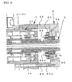
- FIG. 9 is a sectional view in which a portion coupling the guide bush support table to the head stock after switching is enlarged.
- Best Mode for Carrying out the Invention
- One preferred embodiment of the present invention will hereinafter be described in detail with reference to the drawings.
- FIG. 1 concerns one embodiment of an automatic lathe of the present invention, wherein FIG. 1(a) is a sectional view explaining the configuration of essential parts including a guide bush support table and a head stock, and FIG. 1(b) is a front view of the guide bush support table in FIG. 1(a).
- It is to be noted that in the following description, "front", when referred to, indicates a front end side of a spindle provided with a spindle chuck which grips a rod material, that is, the left side in FIG. 1(a), while "rear", when referred to, indicates a rear end side of the spindle, that is, the right side in FIG. 1(a).
- As shown in FIG. 1(a), the automatic lathe in this embodiment has: a
slide guide 2 provided on an unshown bed; ahead stock 6 which freely moves in forward and backward directions on theslide guide 2; a guide bush support table 1 disposed in front of thehead stock 6 and capable of moving in the forward and backward directions on theslide guide 2; aspindle 3 rotatably supported on thehead stock 6 and provided so as to freely move in forward and backward directions with respect to the guide bush support table 1; aguide bush 4 rotatably provided on the guide bush support table 1 in front of thespindle 3 and on the same axis line C as thespindle 3; atool post 5 equipped with a plurality of tools T to machine the rod material protruding from theguide bush 4; a collet open/close member 61 which is provided in the rear of thehead stock 6 and which opens/closes acollet chuck 32 that is a spindle chuck fitted to the front end of thespindle 3; and aspindle moving member 7 which moves thespindle 3 together with thehead stock 6 in the forward and backward directions. - As shown in FIG. 1(b), the slide guides 2 are arranged in parallel on both sides under the guide bush support table 1 and the
head stock 6, and thehead stock 6 and the guide bush support table 1 can smoothly move forward and backward by thespindle moving member 7 provided under the slide guides 2, under the guidance of the slide guides 2. - FIG. 2 is a view in which the guide bush support table in FIG. 1(a) is enlarged.
- A
motor 11 which is guide bush driving means is incorporated in the guide bush support table 1, and aguide sleeve 12 which rotates on the axis line C is fitted to a rotor 11a of themotor 11. Theguide sleeve 12 is rotatably supported bybearings guide sleeve 12 is held by a bearingholder 14 fitted to the front end of the guide bush support table 1. Therefore, the front end of theguide sleeve 12 is supported by thebearing 13 and the bearingholder 14. - The
guide bush 4 is fitted to the front end of theguide sleeve 12 via acylindrical attachment 41 which is guide bush fitting means. Thisattachment 41 has a large diameter hole 41a which receives a main body part of theguide bush 4, and a small diameter hole 41b which is formed in the rear of the large diameter hole 41a and into which a screw portion formed in the body of theguide bush 4 screws. - The main body part of the
guide bush 4 is inserted into the large diameter hole 41a of theattachment 41, and the screw portion formed in the body thereof is inserted through the small diameter hole 41b to protrude therefrom, and then a nut 42 is screwed in and fastened to the screw portion, thus fitting theguide bush 4 to theattachment 41. Then, after inserted from the front end side of theguide sleeve 12, theattachment 41 fitted with theguide bush 4 is detachably fitted to the front end of theguide sleeve 12 by a plurality ofbolts 43. Further, acylindrical cover 45 is fitted to the outside of theattachment 41 to prevent foreign matter such as cutting chips from entering the guide bush support table 1 from a gap between theguide sleeve 12 and theattachment 41. Thecover 45 is fitted to a front end surface of the bearingholder 14 by a plurality ofbolts 46. - The
tool post 5 has atool post base 51 fixed to the unshown bed, asaddle 53 which freely moves forward and backward in a Y direction (direction rectangular to the surface of the drawing) with respect to thetool post base 51 under the guidance of aguide 52 of thetool post base 51, and atool fitting member 55 which freely moves forward and backward in an X direction (vertical direction in the drawing) with respect to thesaddle 53 under the guidance of a guide 54 provided in thesaddle 53. The plurality of tools T is arranged in a comb-teeth manner and fitted to thetool fitting member 55. Then, thetool fitting member 55 is moved in the Y direction to determine the predetermined tool T to be used for machining from the plurality of tools T, and the cutting edge of the tool T is located in the vicinity of theguide bush 4 to machine the rod material. - It is to be noted that the guide bush support table 1 is fitted to the
tool post base 51 by a plurality ofbolts 15, and when the rod material is machined using theguide bush 4, the guide bush support table 1 is in a fixed state so as not to move on theslide guide 2. - Furthermore, as in this embodiment, when the guide bush support table 1 is fitted to the
tool post base 51 to regulate its movement, thebolts 15 to be used are preferably formed of a material having low heat transmitting properties such as ceramic so that the heat is not transmitted from the guide bush support table 1 to thetool post base 51. Moreover, aspacer 58 formed of a material having low heat transmitting properties is preferably placed at a contact portion between the guide bush support table 1 and thetool post base 51. - In the
spindle 3, a through-hole 3a is formed on the axis line C, and thecollet chuck 32 which grips the rod material is fitted to the front end of the through-hole 3a. Thecollet chuck 32 is inserted into the front end of acylindrical collet sleeve 34, and inserted into the front end of thespindle 3 together with thecollet sleeve 34. Further, acap nut 33 which receives the front ends of thecollet chuck 32 and thecollet sleeve 34 is screwed in and fastened to a screw portion 3b formed on an outer peripheral surface of the front end of thespindle 3, thereby regulating thecollet sleeve 34 and thecollet chuck 32 so that they may not escape from thespindle 3. - A cam to open/close the
collet chuck 32 is formed on an inner peripheral surface at the front end of thecollet sleeve 34. Further, thecollet sleeve 34 is capable of slight amount of forward and backward movement inside thecap nut 33 fitted to thespindle 3, and thecollet sleeve 34 moves forward and backward with respect to thecollet chuck 34 such that thecollet chuck 32 is opened/closed by the cam. - The forward and backward movement of the
collet sleeve 34 is performed by a draw bar 35 (see FIG. 1) provided in the rear of thecollet sleeve 34. Inside thedraw bar 35, a through-hole through which the rod material can be inserted is formed on the axis line C. The front end of thedraw bar 35 butts against the rear end of thecollet sleeve 34, and if thedraw bar 35 moves forward to push thecollet sleeve 34 forward, the cam of thecollet sleeve 34 closes thecollet chuck 32. Moreover, a return spring 34a is provided inside thecollet sleeve 34, and always urges thecollet chuck 32 in a direction to press it against thecap nut 33, that is, in a forward direction. Then, when thedraw bar 35 moves backward, thecollet sleeve 34 is pressed back with respect to thecollet chuck 32 by the return spring 34a, thereby opening thecollet chuck 32. The forward and backward movement of thedraw bar 35 is performed by the known collet open/close member 61 provided in ahousing 60 on the rear end side of thespindle 3. - As shown in FIG. 1, a
bearing 62 is fitted to the front end of thehousing 60 by a bearingholder 64. The rear end of thespindle 3 is rotatably supported by thisbearing 62. Moreover, astep portion 39 is formed on the outer peripheral surface of thespindle 3 forward of thebearing 62, and thisstep portion 39 and anut 63 which is screwed in from the rear end of thespindle 3 hold the bearing 62 from its front and rear. - Furthermore, a
motor 8 as spindle driving means for rotating thespindle 3 is incorporated in thehead stock 6. The driving of thismotor 8 is controlled together with amotor 73 and themotor 11 by a control device of the automatic lathe. - FIG. 3 is a block diagram of the control device which controls the driving of the
motor 8 and themotor 11. - As shown in FIG. 3, a
control device 120 comprises a first control system having a speed processing unit 121 which outputs a speed signal based on a command from the control device (CPU) of the automatic lathe, and aservo processing unit 122 which drives themotor 8 on the basis of an output signal from the speed processing unit 121; and a second control system having aspeed processing unit 123 which outputs a speed signal based on a command from the control device (CPU), and aservo processing unit 124 which drives themotor 11 on the basis of an output signal from thespeed processing unit 123. In an example shown in FIG. 3, there are provided thespeed processing units 121 and 123 corresponding to themotors motors - In the
control device 120 described above, when commands to drive themotor 8 and themotor 11 are output, the CPU transmits command signals to the speed processing unit 121 and thespeed processing unit 123 to synchronize the driving of themotor 8 and themotor 11. - Thus, the load on the
spindle 3 is dispersed to the twomotors motors head stock 6 and the guide bush support table 1 can be minimized. Moreover, because the twomotors spindle 3 rotate thespindle 3 while equally dispersing the load, a torsion of thespindle 3 on the front end and rear end sides thereof can be suppressed. - Furthermore, both the
motors - The
spindle 3 is fitted to a rotor 8a of themotor 8. As shown in FIG. 1, a bearing holder 65 is fitted to the front end of thehead stock 6, and thespindle 3 is supported by a bearing 66 which is held by the bearing holder 65 to prevent forward and backward movement. Further, anut 38 screwed in at a middle part of thespindle 3 to hold the bearing presses the bearing 66 against a stepped portion of thespindle 3 formed in the rear of the bearing 66, such that the forward and backward movement of thespindle 3 with respect to thehead stock 6 is regulated via the bearing holder 65 and the bearing 66. - The
head stock 6 freely moves forward and backward in the same direction as the axis line C under the guidance of theslide guide 2, and thespindle moving member 7 which moves thespindle 3 forward and backward together with thehead stock 6 is provided under thehead stock 6. - The
spindle moving member 7 has ascrew shaft 71 extending in the same direction as the axis line C, themotor 73 which rotates thescrew shaft 71, and a nut 72 screwed in thescrew shaft 71. Thehead stock 6 is coupled to the nut 72, and moved forward and backward in the same direction as the axis line C together with the nut 72 by the rotation of thescrew shaft 71 caused by the driving of themotor 73. - In the automatic lathe having the configuration described above, the rod material is supplied from the rear end of the
spindle 3 through the through-hole 3a. Then, thedraw bar 35 is moved forward while the front end of the rod material is protruding from theguide bush 4 at a predetermined length, and thecollet chuck 32 is closed to grip the rod material. Subsequently, themotor 8 and themotor 11 are synchronously driven to rotate thespindle 3 and theguide bush 4 at the same speed. Then, themotor 73 of thespindle moving member 7 is driven so that the rod material is fed by predetermined length together with thespindle 3 in the same direction (Z direction) as the axis line C, thus performing predetermined machining with the tool T. - Next, there will be described with reference to FIGS. 4 and 5 a switching procedure of removing the
guide bush 4 from the automatic lathe having the configuration described above and switching to an automatic lathe which does not comprise theguide bush 4. - First, as shown in FIG. 4(a), the
tool fitting member 55 is moved in the X direction to move the tool T away from theguide bush 4 to a position where the switching operation is not disturbed. - Then, as shown in FIG. 4(b), the
bolt 46 is removed to remove thecover 45 from the bearingholder 14, and thebolt 43 is removed to remove theattachment 41 and theguide bush 4 from theguide sleeve 12. - Furthermore, the
motor 73 of thespindle moving member 7 is driven to move thespindle 3 backward together with thehead stock 6, thus securing a sufficient space between thehead stock 6 and the guide bush support table 1. Instead of driving themotor 73, thehead stock 6 may be manually moved backward. When thehead stock 6 is moved backward, the front end of thespindle 3 escapes from theguide sleeve 12 and is located between thehead stock 6 and the guide bush support table 1. In this state, as shown in FIG. 4(c), thecap nut 33 is removed from the front end of thespindle 3, and thecollet chuck 32 is pulled from the through-hole 3a of thespindle 3 together with thecollet sleeve 34. - Next, a cylindrical
spindle coupling nut 37 as shown in FIG. 5(a) is prepared, and inserted into and fitted to the rear end of theguide sleeve 12. Thespindle coupling nut 37 comprises a nut main body part 37a having an outside diameter slightly smaller than the inside diameter of theguide sleeve 12 and having an inside diameter identical with the outside diameter of thespindle 3; a screw portion 37b which is formed on an outer peripheral surface of the rear end of the main body part 37a and which is to be screwed in a screw portion 12a formed on an inner peripheral surface of the rear end of theguide sleeve 12; a flange portion 37c formed at a peripheral edge of an opening at the rear end of the screw portion 37b; a screw portion 37d which is formed on an inner peripheral surface of the front end of the main body part 37a and into which the screw portion 3b at the front end of thespindle 3 is screwed; and an annular pendent portion 37e formed diametrically inward at a peripheral edge of an opening at the front end of the main body part 37a. - The
spindle coupling nut 37 having the configuration described above is inserted into the rear end of theguide sleeve 12 so that the screw portion 37b is screwed in the screw portion 12a and fastened thereto until the flange portion 37c contacts the rear end of theguide sleeve 12, thereby fitting thespindle coupling nut 37 to theguide sleeve 12. - Next, as shown in FIG. 5(b), the plurality of
bolts 15 coupling the guide bush support table 1 to thetool post base 51 is removed to cancel the fixing of the guide bush support table 1. This allows the guide bush support table 1 to freely move forward and backward on theslide guide 2, so that the front end of thespindle 3 is inserted into thespindle coupling nut 37 while the guide bush support table 1 is being manually moved toward thehead stock 6. Moreover, while thespindle 3 is being moved, the screw portion 3b of thespindle 3 is screwed in the screw portion 37d of thespindle coupling nut 37, and fastened thereto until the front end of thespindle 3 contacts the flange portion 37e. - In this manner, the
spindle 3 is coupled to theguide sleeve 12 via thespindle coupling nut 37, and the forward and backward movement of thespindle 3 with respect to the guide bush support table 1 is regulated. Moreover, the rotation can be transmitted between theguide sleeve 12 and thespindle 3 via thespindle coupling nut 37. In this embodiment, thespindle coupling nut 37 forms spindle fixing means for positioning and fixing thespindle 3 at a specified position on the guide bush support table 1. - Subsequently, as shown in FIG. 5(b), a collet sleeve 34' formed for the automatic lathe which does not comprise the
guide bush 4 is prepared, and thecollet chuck 32 is inserted into the front end of the collet sleeve 34' and then inserted into the through-hole 3a of thespindle 3 from the front end of theguide sleeve 12. - Furthermore, as shown in FIG. 5(c), a cap nut 33' formed for the automatic lathe which does not comprise the
guide bush 4 is fitted in a screwed state to the screw portion of theguide sleeve 12, thereby regulating the collet sleeve 34' and thecollet chuck 32 so that they do not escape from the front end of thespindle 3. At this point, since the rear end of the collet sleeve 34' is in contact with the tip of thedraw bar 35, thecollet chuck 32 can be opened/closed by the forward and backward movement of thedraw bar 35. In this embodiment, the collet sleeve 34' forms a chuck positioning member which positions thecollet chuck 32 when thecollet chuck 32 grips the rod material. - Furthermore, a cover 45' formed for the automatic lathe which does not comprise the
guide bush 4 is fitted to the front end of the bearingholder 14 by thebolts 46. - This completes the switching. Thus, a chuck mechanism to grip the rod material is assembled at the front end of the
guide sleeve 12 fitted with theguide bush 4. In addition, when the rod material is machined, theguide sleeve 12 serves as the spindle. - FIG. 6 is a sectional view showing the essential part of the automatic lathe after the switching has been performed by the procedure described above.
- As shown in FIG. 6, the guide bush support table 1 after the switching is decoupled from the
tool post base 51, and can move forward and backward in the same direction as the axis line C under the guidance of theslide guide 2. Moreover, since the guide bush support table 1 is coupled to thespindle 3 and thehead stock 6 by thespindle coupling nut 37 via theguide sleeve 12, the guide bush support table 1, thehead stock 6 and thespindle 3 integrally move forward and backward in the same direction as the axis line C owing to thespindle moving member 7 which moves thespindle 3 forward and backward. That is, after the switching, the guide bush support table 1 and thehead stock 6 form a movable head stock. - Furthermore, the rod material is gripped by the
collet chuck 32 in a state protruding from the front end of thespindle 3 at a predetermined length, and thespindle 3 is fed to the tool T together with the guide bush support table 1 and thehead stock 6 in the Z direction (the same direction as the axis line C), thus machining the rod material. - As described above, since the
guide sleeve 12 serves as the spindle when the rod material is machined, the high rigidity of the tip of the spindle is kept during the machining of the rod material, thereby allowing the rod material to be highly accurately machined. - FIGS. 7 to 9 concerns another embodiment of the present invention. FIG. 7(a) is a sectional view in which parts corresponding to the rear end of the guide bush support table and the front end of the head stock before the switching are enlarged. FIG. 7(b) is a sectional view in which the essential part in FIG. 7(a) is further enlarged. FIG. 8 is a sectional view in which a part corresponding to a bearing portion supporting the rear end of the spindle is enlarged. FIG. 9 is a sectional view in which a portion coupling the guide bush support table to the head stock after the switching is enlarged.
- In the embodiment previously described, the
head stock 6 is coupled to the guide bush support table 1 by thespindle coupling nut 37, but in this embodiment, another coupling means (coupling member 69) is used in addition to thespindle coupling nut 37 to couple the guide bush support table 1 to thehead stock 6. Thus, in a case where the rod material is machined without using theguide bush 4, the use of another coupling means makes it possible to reduce the burden on thespindle 3 when thespindle 3 is moved together with the guide bush support table 1 and thehead stock 6. - As shown in FIG. 7(a), the bearing holder 65 holding the bearing 66 is fitted to a front end surface of the
head stock 6 by at least onebolt 80 so as not to drop from thehead stock 6 and so as not to rotate with respect to thehead stock 6. - As shown in FIG. 7(b), the
bolt 80 is equipped with awasher 81 and asleeve 82 in a fitted state. Thebolt 80, thewasher 81 and thesleeve 82 are inserted in a bolt hole 65b formed in the flange portion of the bearing holder 65, and screwed into a screw hole in the front end surface of thehead stock 6 through a through-hole 65c formed at the bottom of the bolt hole 65b. Since the length of the sleeve 82 (the length in the axis line C direction) is formed larger than the thickness of the bottom of the bolt hole 65b, a small amount of space S1 is formed between the flange portion of the bearing holder 65 and the front end surface of thehead stock 6 and between thewasher 81 and the bottom of the bolt hole 65b when thebolt 80 is tightened. - It is to be noted that a stepped bolt in which a diameter in a shaft portion is larger than a diameter in a helical portion may be used instead of the
washer 81 and thesleeve 82. - The dimensions of the space S1 should be larger than a maximum value of a thermal expansion amount of the
spindle 3 at the front end of thehead stock 6. In this embodiment, the space S1 forms a thermal expansion absorption member which absorbs a dimensional change due to the thermal expansion of thespindle 3. Further, in this embodiment, thebolt 80 and thesleeve 82 form a space between the bearing holder 65 and thehead stock 6, and form a fitting member which prevents the bearing holder 65 from rotating with respect to the head stock. - Furthermore, as shown in FIG. 7(a), a halved or trisected
bearing fixing member 67 is annually disposed around the bearing holder 65, and fitted to the front end surface of thehead stock 6 by a bolt 67a in a state engaged with the bearing holder 65. Further, the bearing holder 65 is coupled to thebearing fixing member 67 by a plurality of bolts 67b. Thus, the bearing holder 65 is fixed to thehead stock 6 via thebearing fixing member 67. Since thespindle 3 and the bearing holder 65 are regulated so as not move with respect to each other as previously described, the bearing holder 65 is fixed to thehead stock 6 via thebearing fixing member 67 such that the forward and backward movement of thespindle 3 with respect to thehead stock 6 is also regulated. That is, in this embodiment, the bearing holder 65 forms an engaging member of regulating means for engaging with thespindle 3 to regulate the forward and backward movement of thespindle 3 with respect to thehead stock 6. - It is to be noted that in FIG. 7, a numeral 68 denotes a bearing holder which holds an outer ring of the bearing 66 from a front end side thereof, and it is fitted to the bearing holder 65 by a bolt 68a.
- The bearing 62 supporting the rear end of the
spindle 3 has, as shown in FIG. 8, an inner ring 62a thereof held from the front and rear thereof between thenut 63 described above and thestep portion 39 of thespindle 3, and regulated so as not to move forward and backward with respect to thespindle 3. On the other hand, a protrusion 64a projecting inward in the diametrical direction is formed at the front end of the bearingholder 64, and a ring-shaped holding member 64b is fitted to the rear end of the bearingholder 64. Moreover, spaces S2 and S3 which absorb the thermal expansion of thespindle 3 are formed between the front end of an outer ring 62b and the protrusion 64a and between the rear end of the outer ring 62b and the holding member 64b. Thebearing 62 is capable of moving forward and backward together with thespindle 3 with respect to thebearing holder 64 to the extent corresponding to the spaces S2 and S3. The dimensions of the spaces S2 and S3 should be greater than the thermal expansion amount of thespindle 3 due to the heating of the rotors 8a and 11a of themotors - As shown in FIG. 9, after the
guide bush 4 has been removed, the guide bush support table 1 is coupled to thehead stock 6 by thecoupling member 69. A procedure of coupling the guide bush support table 1 to thehead stock 6 by the coupling means 69 is as follows. - Before the procedure of coupling the
spindle 3 to the guide bush support table 1 by thespindle coupling nut 37 described in the previous embodiment, thehead stock 6 is moved backward from the guide bush support table 1 to secure a sufficient space between thehead stock 6 and the guide bush support table 1. Then, the bolts 67a and 67b are removed to remove, from the front end surface of thehead stock 6, thebearing fixing member 67 fixing the bearing holder 65 to thehead stock 6. Subsequently, a plurality ofcoupling members 69 is disposed on the circumference of the front end surface of thehead stock 6 around the axis line C, and a bolt 69a is inserted into a bolt hole 1a penetrating from a front end surface to a rear end surface of the guide bush support table 1, and then the guide bush support table 1 and thecoupling members 69 are inserted therethrough, thus screwing the bolt 69a into a screw hole formed in the front end surface of thehead stock 6. Then, the bolt 69a is tightened, and the guide bush support table 1 is coupled to thehead stock 6 by thecoupling members 69 while the guide bush support table 1 and thehead stock 6 are being moved in a direction to approach each other. - In this case, if the
bearing fixing member 67 is removed from thehead stock 6, the fixing of the bearing holder 65 to thehead stock 3 in the axis line C direction is cancelled, but thespindle 3 is fitted to the guide bush support table 1 so as not to move forward and backward. Therefore, after thehead stock 6 is coupled to the guide bush support table 1 by thecoupling members 69, thespindle 3 and the bearing holder 65 do not freely move forward and backward with respect to thehead stock 6 even if thebearing fixing member 67 is removed. If thespindle 3 expands due to the heat of the rotor 11a of themotor 11, the bearing holder 65 moves within the range of a space S due to the thermal expansion and absorbs the thermal expansion of thespindle 3. - This embodiment has an advantage that it is not at all necessary for an operator to remove or loosen the
bolt 80 fitting the bearing holder 65 to the front end surface of thehead stock 6 during the switching, and that the switching operation can be easily and rapidly performed by anyone who is not a skilled operator or a person in charge of a manufacturer that has manufactured and sold the automatic lathe. Moreover, the bearing holder 65 does not separate from thehead stock 6 owing to thebolt 80, such that the displacement of the core of thespindle 3 due to the separation of the bearing holder 65 from thehead stock 6 is avoided and the safety of the operator can be secured. - When the
guide bush 4 is removed from the front end of theguide sleeve 12 to switch to the automatic lathe which does not comprise theguide bush 4, the bolt 67a fitting thefitting member 67 to thehead stock 6 and the bolts 67b coupling thefitting member 67 to the bearing holder 65 are removed, and thefitting member 67 is removed from the front end surface of thehead stock 6. Subsequently, as described in the previous embodiment, thecoupling members 69 are used to couple the guide bush support table 1 to thehead stock 6. Further, the rear end of the guide bush support table 1 is coupled to the front end of thehead stock 6 by the plurality ofcoupling members 69. - Since the guide bush support table 1 is firmly coupled to the
head stock 6 by thecoupling members 69, the space therebetween does not change even if thespindle 3 thermally expands in the axis line C direction due to the heat of the rotors 8a and 11a of themotors spindle 3 due to the thermal expansion is absorbed by the space S1 between the bearing holder 65 and the front end surface of thehead stock 6 and the spaces S2 and S3 between the bearing 66 and the bearing holder 65. That is, in this embodiment, these spaces S1, S2 and S3 form the thermal expansion absorption members which absorb the dimensional change of thespindle 3 due to the thermal expansion. - While the preferred embodiments of the present invention have been described, the present invention is not at all limited by the embodiments described above.
- For example, the spindle-moving-type automatic lathe has been described above by way of example wherein the
head stock 6 moves together with the guide bush support table 1 after the switching, but when there is provided a tool post movable in the Z direction, the present invention can also be applied to a spindle-fixed-type automatic lathe wherein thehead stock 6 and the guide bush support table 1 are fixed onto the bed. In this case, when the switching is performed, a driving system of thespindle moving member 7 should be separated from the control system of the automatic lathe without removing thebolts 15 coupling the guide bush support table 1 to thetool post base 51. - Furthermore, a spacer with a predetermined width is placed between the
tool post base 51 and the front end surface of the guide bush support table 1, and this spacer is removed from the guide bush support table 1, for example, when theguide bush 4 is fitted, thereby allowing adjustment of the position of theguide bush 4 of the front end of thespindle 3 before and after the switching. - Still further, in the above description, the collet sleeve 34' formed for the automatic lathe which does not comprise the
guide bush 4 and thecollet chuck 32 are inserted from the front end of theguide sleeve 12 after the coupling of thehead stock 6 to the guide bush support table 1 and then attached to the spindle 3 (see FIG. 5(b)). However, the collet sleeve 34' and thecollet chuck 32 may be inserted from the front end of thespindle 3 immediately after the step shown in FIG. 4(c). - The present invention can be applied to a spindle-moving-type automatic lathe and a spindle-fixed-type automatic lathe, and can also be applied to a numerically controlled automatic lathe which performs, in accordance with a program, feeding and stopping of a rod material, determining and positioning of a tool, machining of the rod material with the tool, and parting of a machined product.
- Furthermore, the present invention is not limited to an automatic lathe of a type which supplies a long rod material from a rod material supply device disposed in the rear of the automatic lathe, but the present invention can also be applied to an automatic lathe of a type which supplies a relatively short rod-like material to a collet at the front end of a spindle by use of, for example, a robot hand.
- Still further, the present invention is not limited to a built-in type automatic lathe incorporating a motor in a guide bush support table, but the present invention can also be applied to an automatic lathe of a type in which a motor is provided outside a guide bush support table and the driving force of this motor is transmitted to a spindle by a driving force transmission mechanism such as a belt or pulley.
Claims (12)
- An automatic lathe which has a tool post and a spindle configured to relatively move in a spindle axis line direction and which machines a material gripped by a spindle chuck at the tip of the spindle by use of a tool installed on the tool post, the automatic lathe characterized by comprising:a head stock configured to move forward and backward;the spindle rotatably supported on the head stock and having a through-hole formed for the rod-like material to be inserted therethrough;spindle driving means which is provided in the head stock to rotate the spindle;the tool post equipped with a tool to machine the material gripped by the spindle chuck;a guide bush support table disposed closer to a tip side of the spindle than the head stock;support table fixing means for positioning and fixing the guide bush support table at a specified position of a bed;a guide member which is rotatably supported on the guide bush support table and which is regulated so as not to move forward and backward with respect to the guide bush support table and in which a through-hole is formed to insert the spindle therein;a guide bush detachably fitted to the tip of the guide member;guide bush driving means which is provided in the guide bush support table to rotate the guide member together with the guide bush;spindle moving means for moving the spindle forward and backward together with the head stock inside the guide member;spindle fixing means for preventing the spindle from moving forward and backward with respect to the guide bush support table, and positioning and fixing the spindle at a specified position on the guide bush support table when the guide bush is removed from the guide member; andcontrol means for performing synchronous control of the spindle driving means and the guide bush driving means when machining the material by use of at least the guide bush.
- The automatic lathe according to claim 1, characterized in that a guide is provided to guide the forward and backward movement of the guide bush support table so that the guide bush support table is movable along the guide when the fixing of the guide bush support table by the support table fixing means is cancelled, and that when the guide bush is removed to machine the material without using the guide bush, the material gripped by the spindle chuck is machined while the head stock and the guide bush support table are being integrally moved forward and backward.
- The automatic lathe according to claim 1 or 2, characterized in that the support table fixing means has a positioning member positioned and fixed on the bed, and a bolt coupling the positioning member to the guide bush support table.
- The automatic lathe according to claim 3, characterized in that a spacer with a specified width is placed between the positioning member and the guide bush support table so that the position of the guide bush or the tip of the spindle is adjustable when the guide bush is fitted or removed.
- The automatic lathe according to claim 3 or 4, characterized in that the positioning member is a tool post base which supports the tool post.
- The automatic lathe according to any one of claims 1 to 5, characterized in that rotation transmission means for transmitting the rotation of the guide member to the spindle when the guide bush is removed is provided between the guide member and the spindle, so that the rotation of the guide member is transmitted to the spindle.
- The automatic lathe according to claim 6, characterized in that the control means controls the driving of both the spindle driving means and the guide bush driving means in accordance with a cutting condition in order to use the spindle driving means and the guide bush driving means to drive the spindle when the material is machined without using the guide bush.
- The automatic lathe according to any one of claims 1 to 7, characterized in that when the guide bush is removed, the spindle chuck and a cam member which opens/closes the spindle chuck are removed from the spindle and located inside the tip of the guide member, and a chuck positioning member is fitted to the tip of the guide member to position the spindle chuck when the spindle chuck grips the material, thereby incorporating, in the tip of the guide member, a mechanism similar to a chuck mechanism of the spindle which grips the material during machining.
- The automatic lathe according to any one of claims 1 to 8, characterized in that when the guide bush is removed from the guide member, the head stock is coupled to the guide bush support table by coupling means.
- The automatic lathe according to claim 9, characterized in that a thermal expansion absorption member which absorbs a dimensional change of the spindle due to thermal expansion is provided in at least one place of the spindle.
- The automatic lathe according to claim 10, characterized in that the thermal expansion absorption member has regulating means for regulating the spindle so that the spindle does not to move forward and backward with respect to the head stock when the guide bush is fitted, and regulation canceling means for canceling the regulation of the spindle by the regulating means.
- The automatic lathe according to claim 11,
characterized in that the regulating means comprises an engaging member which engages with the spindle in the front and rear on the spindle axis line, and a fitting member which fits the engaging member to the head stock so that the engaging member does not rotate with respect to the head stock and so that the engaging member has a gap of preset dimensions in the spindle axis line direction without separating from the head stock when the regulation of the spindle is cancelled by the regulation canceling means; and
the regulation canceling means is a fitting member which fits and fixes the engaging member onto the head stock.
Applications Claiming Priority (1)
| Application Number | Priority Date | Filing Date | Title |
|---|---|---|---|
| PCT/JP2003/016928 WO2005065870A1 (en) | 2003-12-26 | 2003-12-26 | Automatic lathe |
Publications (3)
| Publication Number | Publication Date |
|---|---|
| EP1704950A1 true EP1704950A1 (en) | 2006-09-27 |
| EP1704950A4 EP1704950A4 (en) | 2008-08-27 |
| EP1704950B1 EP1704950B1 (en) | 2010-07-14 |
Family
ID=34746770
Family Applications (1)
| Application Number | Title | Priority Date | Filing Date |
|---|---|---|---|
| EP03786356A Expired - Lifetime EP1704950B1 (en) | 2003-12-26 | 2003-12-26 | Automatic lathe |
Country Status (8)
| Country | Link |
|---|---|
| US (1) | US7464628B2 (en) |
| EP (1) | EP1704950B1 (en) |
| JP (1) | JP4455501B2 (en) |
| KR (1) | KR101052019B1 (en) |
| CN (1) | CN1886222B (en) |
| AU (1) | AU2003296150A1 (en) |
| DE (1) | DE60333406D1 (en) |
| WO (1) | WO2005065870A1 (en) |
Cited By (4)
| Publication number | Priority date | Publication date | Assignee | Title |
|---|---|---|---|---|
| WO2010040680A3 (en) * | 2008-10-07 | 2010-10-07 | Traub Drehmaschinen Gmbh & Co. Kg | Lathe |
| CN104708030A (en) * | 2013-12-12 | 2015-06-17 | 铜陵市永生机电制造有限责任公司 | Method for turning guide cylinder special for thin rod |
| WO2016199047A1 (en) | 2015-06-11 | 2016-12-15 | Watch Out Sa | Lathe and guide bush |
| WO2021111171A1 (en) * | 2019-12-04 | 2021-06-10 | Haute Ecole Arc Ingénierie | Driving tool for clamping and driving a rod involved in machining operations and method using the same |
Families Citing this family (14)
| Publication number | Priority date | Publication date | Assignee | Title |
|---|---|---|---|---|
| AU2003296140A1 (en) * | 2003-12-26 | 2005-08-12 | Citizen Watch Co., Ltd. | Automatic lathe |
| US20070199415A1 (en) * | 2004-03-31 | 2007-08-30 | Yosuke Ando | Material Guide Device And Automatic Lathe |
| WO2008081744A1 (en) * | 2006-12-28 | 2008-07-10 | Seiko Instruments Inc. | Lathe |
| JP4988427B2 (en) * | 2007-05-10 | 2012-08-01 | スター精密株式会社 | Machine Tools |
| US8904893B2 (en) | 2010-12-06 | 2014-12-09 | Gm Global Technology Operations, Llc | Method of controlling a dual clutch transmission |
| KR101862602B1 (en) * | 2011-01-19 | 2018-05-31 | 두산공작기계 주식회사 | the guide bush device of the turret install type |
| CN112620663B (en) * | 2013-03-18 | 2023-07-21 | 西铁城时计株式会社 | Guide bush control device and guide bush adjustment method |
| JP6372383B2 (en) * | 2015-02-09 | 2018-08-15 | スター精密株式会社 | Machine Tools |
| CN104816097B (en) * | 2015-05-11 | 2016-08-24 | 武汉思瑞法机器人制造有限公司 | Frock clamp and pipeline laser cutting machine for pipeline laser cutting machine |
| JP6867957B2 (en) * | 2016-02-04 | 2021-05-12 | シチズン時計株式会社 | Machine tools and control devices for those machine tools |
| EP3513905B1 (en) * | 2018-01-19 | 2023-07-26 | Gildemeister Italiana S.r.l. | Spindle apparatus for use in machine tool, in particular a lathe, and machine tool with such spindle apparatus |
| JP7464816B2 (en) * | 2019-12-20 | 2024-04-10 | スター精密株式会社 | Lathe and method for attaching guide member thereto |
| KR102374050B1 (en) * | 2020-10-14 | 2022-03-11 | 현대위아 주식회사 | Millhead for Composite Machine Tool |
| US11833630B2 (en) | 2021-05-28 | 2023-12-05 | Yamazaki Mazak Corporation | Machine tool with removable workpiece support |
Citations (3)
| Publication number | Priority date | Publication date | Assignee | Title |
|---|---|---|---|---|
| JPH09225703A (en) * | 1996-02-16 | 1997-09-02 | Tsugami Corp | Main spindle moving type lathe |
| JPH1110405A (en) * | 1997-06-26 | 1999-01-19 | Star Micronics Co Ltd | Guide bush device for automatic lathe |
| EP1203634A1 (en) * | 2000-11-02 | 2002-05-08 | IEMCA Giuliani Macchine Italia S.p.A. | Transfer type machine tool |
Family Cites Families (9)
| Publication number | Priority date | Publication date | Assignee | Title |
|---|---|---|---|---|
| US2273369A (en) * | 1940-06-24 | 1942-02-17 | Pontus W G Nielson | Metal-turning-lathe attachment |
| DE2737664A1 (en) * | 1977-08-20 | 1979-02-22 | Index Werke Kg Hahn & Tessky | REVOLVER TURNING MACHINE |
| EP0226836B1 (en) * | 1985-11-26 | 1990-05-23 | Citizen Watch Co. Ltd. | Numerical control machine |
| DE3738059C1 (en) * | 1987-11-09 | 1989-04-20 | Kurt Jauch | Automatic lathe with drivable tool head and guide device for material bars |
| JP2750356B2 (en) | 1989-03-01 | 1998-05-13 | 株式会社ツガミ | Headstock movable lathe |
| JP2896530B2 (en) * | 1990-09-04 | 1999-05-31 | 株式会社ツガミ | Lathe |
| DE4431814A1 (en) * | 1994-09-07 | 1996-03-14 | Index Werke Kg Hahn & Tessky | Automatic material bar feed device for machine tools, in particular automatic lathes |
| US5924344A (en) * | 1995-02-10 | 1999-07-20 | Index-Werke Gmbh & Co. Kg Hahn & Tessky | Lathe |
| DE10194677T1 (en) * | 2000-10-26 | 2003-11-13 | Citizen Watch Co Ltd | Method for controlling a bar feed apparatus in a numerically controlled lathe and a numerically controlled lathe |
-
2003
- 2003-12-26 AU AU2003296150A patent/AU2003296150A1/en not_active Abandoned
- 2003-12-26 KR KR1020067012824A patent/KR101052019B1/en active IP Right Grant
- 2003-12-26 DE DE60333406T patent/DE60333406D1/en not_active Expired - Lifetime
- 2003-12-26 CN CN2003801109181A patent/CN1886222B/en not_active Expired - Fee Related
- 2003-12-26 JP JP2005513098A patent/JP4455501B2/en not_active Expired - Fee Related
- 2003-12-26 EP EP03786356A patent/EP1704950B1/en not_active Expired - Lifetime
- 2003-12-26 US US10/583,727 patent/US7464628B2/en not_active Expired - Fee Related
- 2003-12-26 WO PCT/JP2003/016928 patent/WO2005065870A1/en active Application Filing
Patent Citations (3)
| Publication number | Priority date | Publication date | Assignee | Title |
|---|---|---|---|---|
| JPH09225703A (en) * | 1996-02-16 | 1997-09-02 | Tsugami Corp | Main spindle moving type lathe |
| JPH1110405A (en) * | 1997-06-26 | 1999-01-19 | Star Micronics Co Ltd | Guide bush device for automatic lathe |
| EP1203634A1 (en) * | 2000-11-02 | 2002-05-08 | IEMCA Giuliani Macchine Italia S.p.A. | Transfer type machine tool |
Non-Patent Citations (1)
| Title |
|---|
| See also references of WO2005065870A1 * |
Cited By (9)
| Publication number | Priority date | Publication date | Assignee | Title |
|---|---|---|---|---|
| WO2010040680A3 (en) * | 2008-10-07 | 2010-10-07 | Traub Drehmaschinen Gmbh & Co. Kg | Lathe |
| US9511460B2 (en) | 2008-10-07 | 2016-12-06 | Traub Drehmaschinen Gmbh & Co. Kg | Lathe |
| CN104708030A (en) * | 2013-12-12 | 2015-06-17 | 铜陵市永生机电制造有限责任公司 | Method for turning guide cylinder special for thin rod |
| WO2016199047A1 (en) | 2015-06-11 | 2016-12-15 | Watch Out Sa | Lathe and guide bush |
| CH711179A1 (en) * | 2015-06-11 | 2016-12-15 | Watch Out Sa | Machining lathe comprising a guide tube. |
| CN108136507A (en) * | 2015-06-11 | 2018-06-08 | 谨观股份公司 | Lathe including pilot bushing |
| US10507528B2 (en) | 2015-06-11 | 2019-12-17 | Watch Out Sa | Lathe comprising a guide bush |
| CN108136507B (en) * | 2015-06-11 | 2020-07-03 | 谨观股份公司 | Lathe comprising a guide bush |
| WO2021111171A1 (en) * | 2019-12-04 | 2021-06-10 | Haute Ecole Arc Ingénierie | Driving tool for clamping and driving a rod involved in machining operations and method using the same |
Also Published As
| Publication number | Publication date |
|---|---|
| AU2003296150A1 (en) | 2005-08-12 |
| WO2005065870A1 (en) | 2005-07-21 |
| DE60333406D1 (en) | 2010-08-26 |
| EP1704950A4 (en) | 2008-08-27 |
| CN1886222B (en) | 2010-06-09 |
| CN1886222A (en) | 2006-12-27 |
| US7464628B2 (en) | 2008-12-16 |
| EP1704950B1 (en) | 2010-07-14 |
| KR101052019B1 (en) | 2011-07-26 |
| JPWO2005065870A1 (en) | 2007-07-26 |
| US20070224007A1 (en) | 2007-09-27 |
| KR20060130080A (en) | 2006-12-18 |
| JP4455501B2 (en) | 2010-04-21 |
Similar Documents
| Publication | Publication Date | Title |
|---|---|---|
| EP1704950B1 (en) | Automatic lathe | |
| EP1698416B1 (en) | Automatic lathe | |
| JP2008238374A (en) | Numerically controlled lathe with guide bush and method for processing work therewith | |
| WO2019202779A1 (en) | Machining tool | |
| JPH09108977A (en) | Machine tool | |
| JP4471531B2 (en) | Material gripping device and automatic lathe | |
| JP4637554B2 (en) | Material gripping device, material guiding device and automatic lathe | |
| EP0826452A2 (en) | Turret with device for compensation of torque fluctuations | |
| JPH05237703A (en) | Lathe for working non-circular workpiece | |
| JP2004090170A (en) | Material guiding device and automatic lathe | |
| JPH088054Y2 (en) | Cutting agent supply device for turning machine | |
| JPH11235604A (en) | Nc automatic lathe guide bush adjustment device and adjustment method thereof | |
| JPH0463603A (en) | Thrust automatic regulating tailstock | |
| JPH05305471A (en) | Method for automatically adjusting focus position in laser beam machine | |
| JPH05318206A (en) | Nc lathe and its controlling method | |
| JP2022047987A (en) | Machine tool and control method of machine tool | |
| TW202239504A (en) | machine tool | |
| CN115121817A (en) | Lathe | |
| RU1782704C (en) | Power head | |
| JPH10249668A (en) | Bar delivery mechanism and delivery method of bar feeder | |
| JP2002103104A (en) | Automatic lathe | |
| JPH07100241B2 (en) | Opposite turret of machine tool | |
| JPH063501U (en) | Spindle moving type lathe | |
| JPH07328804A (en) | Guide bush regulation method for automatic nc lathe and its device | |
| JPH06246503A (en) | Automatic lathe |
Legal Events
| Date | Code | Title | Description |
|---|---|---|---|
| PUAI | Public reference made under article 153(3) epc to a published international application that has entered the european phase |
Free format text: ORIGINAL CODE: 0009012 |
|
| 17P | Request for examination filed |
Effective date: 20060622 |
|
| AK | Designated contracting states |
Kind code of ref document: A1 Designated state(s): CH DE FR GB IT LI |
|
| DAX | Request for extension of the european patent (deleted) | ||
| RBV | Designated contracting states (corrected) |
Designated state(s): CH DE FR GB IT LI |
|
| RAP1 | Party data changed (applicant data changed or rights of an application transferred) |
Owner name: CITIZEN HOLDINGS CO., LTD. |
|
| A4 | Supplementary search report drawn up and despatched |
Effective date: 20080729 |
|
| 17Q | First examination report despatched |
Effective date: 20081030 |
|
| GRAP | Despatch of communication of intention to grant a patent |
Free format text: ORIGINAL CODE: EPIDOSNIGR1 |
|
| GRAS | Grant fee paid |
Free format text: ORIGINAL CODE: EPIDOSNIGR3 |
|
| GRAA | (expected) grant |
Free format text: ORIGINAL CODE: 0009210 |
|
| AK | Designated contracting states |
Kind code of ref document: B1 Designated state(s): CH DE FR GB IT LI |
|
| REG | Reference to a national code |
Ref country code: GB Ref legal event code: FG4D |
|
| REG | Reference to a national code |
Ref country code: CH Ref legal event code: EP Ref country code: CH Ref legal event code: NV Representative=s name: ISLER & PEDRAZZINI AG |
|
| REF | Corresponds to: |
Ref document number: 60333406 Country of ref document: DE Date of ref document: 20100826 Kind code of ref document: P |
|
| PLBE | No opposition filed within time limit |
Free format text: ORIGINAL CODE: 0009261 |
|
| STAA | Information on the status of an ep patent application or granted ep patent |
Free format text: STATUS: NO OPPOSITION FILED WITHIN TIME LIMIT |
|
| 26N | No opposition filed |
Effective date: 20110415 |
|
| REG | Reference to a national code |
Ref country code: DE Ref legal event code: R097 Ref document number: 60333406 Country of ref document: DE Effective date: 20110415 |
|
| GBPC | Gb: european patent ceased through non-payment of renewal fee |
Effective date: 20101226 |
|
| REG | Reference to a national code |
Ref country code: FR Ref legal event code: ST Effective date: 20110831 |
|
| PG25 | Lapsed in a contracting state [announced via postgrant information from national office to epo] |
Ref country code: FR Free format text: LAPSE BECAUSE OF NON-PAYMENT OF DUE FEES Effective date: 20110103 |
|
| PG25 | Lapsed in a contracting state [announced via postgrant information from national office to epo] |
Ref country code: GB Free format text: LAPSE BECAUSE OF NON-PAYMENT OF DUE FEES Effective date: 20101226 |
|
| PGFP | Annual fee paid to national office [announced via postgrant information from national office to epo] |
Ref country code: CH Payment date: 20161213 Year of fee payment: 14 Ref country code: DE Payment date: 20161220 Year of fee payment: 14 |
|
| REG | Reference to a national code |
Ref country code: CH Ref legal event code: PFA Owner name: CITIZEN WATCH CO., LTD., JP Free format text: FORMER OWNER: CITIZEN HOLDINGS CO., LTD., JP |
|
| PGFP | Annual fee paid to national office [announced via postgrant information from national office to epo] |
Ref country code: IT Payment date: 20161221 Year of fee payment: 14 |
|
| REG | Reference to a national code |
Ref country code: DE Ref legal event code: R082 Ref document number: 60333406 Country of ref document: DE Representative=s name: KLUNKER, SCHMITT-NILSON, HIRSCH, DE Ref country code: DE Ref legal event code: R081 Ref document number: 60333406 Country of ref document: DE Owner name: CITIZEN WATCH CO., LTD., NISHITOKYO-SHI, JP Free format text: FORMER OWNER: CITIZEN HOLDINGS CO., LTD., TOKYO, JP Ref country code: DE Ref legal event code: R082 Ref document number: 60333406 Country of ref document: DE Representative=s name: KLUNKER IP PATENTANWAELTE PARTG MBB, DE |
|
| REG | Reference to a national code |
Ref country code: DE Ref legal event code: R082 Ref document number: 60333406 Country of ref document: DE Representative=s name: KLUNKER IP PATENTANWAELTE PARTG MBB, DE |
|
| REG | Reference to a national code |
Ref country code: DE Ref legal event code: R119 Ref document number: 60333406 Country of ref document: DE |
|
| REG | Reference to a national code |
Ref country code: CH Ref legal event code: PL |
|
| PG25 | Lapsed in a contracting state [announced via postgrant information from national office to epo] |
Ref country code: DE Free format text: LAPSE BECAUSE OF NON-PAYMENT OF DUE FEES Effective date: 20180703 Ref country code: IT Free format text: LAPSE BECAUSE OF NON-PAYMENT OF DUE FEES Effective date: 20171226 |
|
| PG25 | Lapsed in a contracting state [announced via postgrant information from national office to epo] |
Ref country code: LI Free format text: LAPSE BECAUSE OF NON-PAYMENT OF DUE FEES Effective date: 20171231 Ref country code: CH Free format text: LAPSE BECAUSE OF NON-PAYMENT OF DUE FEES Effective date: 20171231 |