EP1704825B1 - Navigation de fil de guidage - Google Patents
Navigation de fil de guidage Download PDFInfo
- Publication number
- EP1704825B1 EP1704825B1 EP05006219A EP05006219A EP1704825B1 EP 1704825 B1 EP1704825 B1 EP 1704825B1 EP 05006219 A EP05006219 A EP 05006219A EP 05006219 A EP05006219 A EP 05006219A EP 1704825 B1 EP1704825 B1 EP 1704825B1
- Authority
- EP
- European Patent Office
- Prior art keywords
- bone
- guide wire
- distal end
- computer
- orientation
- Prior art date
- Legal status (The legal status is an assumption and is not a legal conclusion. Google has not performed a legal analysis and makes no representation as to the accuracy of the status listed.)
- Expired - Fee Related
Links
Images
Classifications
-
- A—HUMAN NECESSITIES
- A61—MEDICAL OR VETERINARY SCIENCE; HYGIENE
- A61B—DIAGNOSIS; SURGERY; IDENTIFICATION
- A61B90/00—Instruments, implements or accessories specially adapted for surgery or diagnosis and not covered by any of the groups A61B1/00 - A61B50/00, e.g. for luxation treatment or for protecting wound edges
- A61B90/36—Image-producing devices or illumination devices not otherwise provided for
-
- A—HUMAN NECESSITIES
- A61—MEDICAL OR VETERINARY SCIENCE; HYGIENE
- A61B—DIAGNOSIS; SURGERY; IDENTIFICATION
- A61B34/00—Computer-aided surgery; Manipulators or robots specially adapted for use in surgery
- A61B34/20—Surgical navigation systems; Devices for tracking or guiding surgical instruments, e.g. for frameless stereotaxis
-
- A—HUMAN NECESSITIES
- A61—MEDICAL OR VETERINARY SCIENCE; HYGIENE
- A61B—DIAGNOSIS; SURGERY; IDENTIFICATION
- A61B17/00—Surgical instruments, devices or methods, e.g. tourniquets
- A61B17/16—Bone cutting, breaking or removal means other than saws, e.g. Osteoclasts; Drills or chisels for bones; Trepans
- A61B17/17—Guides or aligning means for drills, mills, pins or wires
- A61B17/1703—Guides or aligning means for drills, mills, pins or wires using imaging means, e.g. by X-rays
-
- A—HUMAN NECESSITIES
- A61—MEDICAL OR VETERINARY SCIENCE; HYGIENE
- A61B—DIAGNOSIS; SURGERY; IDENTIFICATION
- A61B17/00—Surgical instruments, devices or methods, e.g. tourniquets
- A61B17/16—Bone cutting, breaking or removal means other than saws, e.g. Osteoclasts; Drills or chisels for bones; Trepans
- A61B17/17—Guides or aligning means for drills, mills, pins or wires
- A61B17/1707—Guides or aligning means for drills, mills, pins or wires using electromagnetic effects, e.g. with magnet and external sensors
-
- A—HUMAN NECESSITIES
- A61—MEDICAL OR VETERINARY SCIENCE; HYGIENE
- A61B—DIAGNOSIS; SURGERY; IDENTIFICATION
- A61B17/00—Surgical instruments, devices or methods, e.g. tourniquets
- A61B17/16—Bone cutting, breaking or removal means other than saws, e.g. Osteoclasts; Drills or chisels for bones; Trepans
- A61B17/17—Guides or aligning means for drills, mills, pins or wires
- A61B17/1717—Guides or aligning means for drills, mills, pins or wires for applying intramedullary nails or pins
-
- A—HUMAN NECESSITIES
- A61—MEDICAL OR VETERINARY SCIENCE; HYGIENE
- A61B—DIAGNOSIS; SURGERY; IDENTIFICATION
- A61B34/00—Computer-aided surgery; Manipulators or robots specially adapted for use in surgery
- A61B34/10—Computer-aided planning, simulation or modelling of surgical operations
- A61B2034/101—Computer-aided simulation of surgical operations
- A61B2034/102—Modelling of surgical devices, implants or prosthesis
-
- A—HUMAN NECESSITIES
- A61—MEDICAL OR VETERINARY SCIENCE; HYGIENE
- A61B—DIAGNOSIS; SURGERY; IDENTIFICATION
- A61B34/00—Computer-aided surgery; Manipulators or robots specially adapted for use in surgery
- A61B34/20—Surgical navigation systems; Devices for tracking or guiding surgical instruments, e.g. for frameless stereotaxis
- A61B2034/2046—Tracking techniques
- A61B2034/2055—Optical tracking systems
-
- A—HUMAN NECESSITIES
- A61—MEDICAL OR VETERINARY SCIENCE; HYGIENE
- A61B—DIAGNOSIS; SURGERY; IDENTIFICATION
- A61B90/00—Instruments, implements or accessories specially adapted for surgery or diagnosis and not covered by any of the groups A61B1/00 - A61B50/00, e.g. for luxation treatment or for protecting wound edges
- A61B90/06—Measuring instruments not otherwise provided for
- A61B2090/067—Measuring instruments not otherwise provided for for measuring angles
-
- A—HUMAN NECESSITIES
- A61—MEDICAL OR VETERINARY SCIENCE; HYGIENE
- A61B—DIAGNOSIS; SURGERY; IDENTIFICATION
- A61B90/00—Instruments, implements or accessories specially adapted for surgery or diagnosis and not covered by any of the groups A61B1/00 - A61B50/00, e.g. for luxation treatment or for protecting wound edges
- A61B90/08—Accessories or related features not otherwise provided for
- A61B2090/0807—Indication means
- A61B2090/0811—Indication means for the position of a particular part of an instrument with respect to the rest of the instrument, e.g. position of the anvil of a stapling instrument
-
- A—HUMAN NECESSITIES
- A61—MEDICAL OR VETERINARY SCIENCE; HYGIENE
- A61B—DIAGNOSIS; SURGERY; IDENTIFICATION
- A61B34/00—Computer-aided surgery; Manipulators or robots specially adapted for use in surgery
- A61B34/10—Computer-aided planning, simulation or modelling of surgical operations
Definitions
- the present invention relates to the technical field of navigation of a guidewire.
- Guidewires are used to "thread" bone fragments after a bone fracture before, for example, inserting an intramedullary nail.
- the guidewire is a long, flexible and relatively thin rod having a proximal end to which the guidewire may be gripped and a distal end that is advanced through the bone channel (s) of the bone fragments to thread the fragments ,
- the proximal end or guidewire is tracked in a long bone using fluoroscopic images (X-rays).
- the position of the guidewire is visualized using a C-arm X-ray machine and, of course, the position of the distal end relative to the bone or the bone fragments.
- the relatively numerous single X-ray images or even continuous X-ray images required hereby bring with them a strong radiation exposure both for the patient and for the treating person.
- Magnetic field navigation or similar types of navigation that navigate or positionally detect hidden instruments within a body are technically complex and prone to failure.
- Optical navigation systems are known, for example from the DE 196 39 615 A1 , the disclosure of which is hereby incorporated by reference.
- From the DE 101 18 570 A1 is a medical device with a flexible bone guidewire known whose position, orientation and shape by means of a navigation system and a fiber optic position sensor can be determined.
- a reference device is arranged, whose position and orientation and thus also the position and orientation of the proximal end of the bone guidewire is detected by means of the navigation system.
- an optical fiber optical fiber position sensor is incorporated in the bone guidewire, from which light may emit, depending on the amount of bending of the fibers.
- the emergent light is detected and, together with the data on the position and orientation of the proximal end of the bone guide wire, fed to a data processing system for calculating the position, orientation and shape of the bone guide wire.
- the fiber optic position sensor is susceptible to mechanical damage. Damaging the reflective surface of individual fibers will affect the light emitted by the fibers, which in turn may lead to erroneous measurements and incorrect calculation of the shape of the bone guide wire.
- the computer assisted position determination may be performed by the computer of the tracking and navigation system.
- the image support method according to the invention for the use of a bone guide wire determines the position of the distal end of the bone guide wire according to the method described above. In addition, this position is output on an image output of the tracking and navigation system in relation to the bone arrangement.
- the computer may be the computer of the tracking and navigation system.
- the tracking and navigation system may include an image output that outputs the detected position of the distal end in relation to the bone assembly.
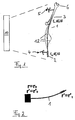
- the in FIG. 1 Guide wire 1 shown has at its proximal end 2 on a handle to which a navigation reference device 4 is attached.
- the navigation reference device 4 and the reference device 5, which is fixed to the illustrated bone 6, are positionally detectable by the navigation and tracking system 10 shown only schematically.
- the system 10 may include tracking cameras, a data processing system, and image output and data input means, for example.
- the system 10 may be a standard optical navigation and tracking system; the reference devices 4 and 5 are designed as reflector stars that reflect invisible (infrared) light.
- the navigation system may be one such as, for example, as a "neuronavigation system" in the DE 196 39 615 A1 is described.
- the navigation and tracking system can determine the position and orientation of the proximal end 2 (r 2 , dr 2 / dl). Also, the position and orientation of the bone 6 can be determined, and in particular the orientation of the inner tube channel in the bone 6. We are looking for the vector r 3 , that is the position of the distal end 3 of the guide wire. 1
- the invention is able to determine the depth of insertion of the distal end 3 under certain conditions with the previously described steps. For this purpose, contrary to all previous approaches in the prior art (magnetic navigation) optical navigation is used.
- the handle of the guide wire distal end 2
- the handle of the guide wire can be easily optically tracked, and because of the known bone alignment (reference device 5), the alignment of the axis of the long bone is known which the guidewire is used. This makes it possible to virtually represent the insertion depth of the guide wire on a computer monitor.
- the invention takes into account the strong bending of the flexible guidewire. This is possible because the orientation of the guidewire in the area of the tip position is known. This knowledge can be used to account for the bend that otherwise could not be detected. There are theoretically very many contours possible, and in FIG. 1 some of them are indicated by the reference numeral 12. So far, optical navigation systems have only been used to track and display rigid bodies in which the position and orientation at a single point determines the position and orientation of the entire structure. The invention described herein makes it possible to track the tip or the distal end of a flexible guidewire without the need for an invasive image acquisition method (Rönten C-arm).
- the present invention and the present disclosure will, in principle, facilitate determining the position of the distal end of any flexible elongate instrument when the conditions described herein are met.
- the orientation in the region of the distal end is known (ie here, for example, any channel is present whose orientation one knows), since the other, proximal end is optically trackable (in position and orientation) and there the flexible instrument has certain physical characteristics, which will be explained in more detail below.
- the navigation system thus tracks and shows the insertion depth for a flexible medical or surgical wire in a long bone.
- the navigation system exists, though in FIG. 1 not shown separately, from a camera system that tracks the position of the reference marker assembly 4 attached to the handle of the guidewire 1 and a reference marker assembly 5 disposed on the tubular bone.
- the navigation software is capable of assigning the three-dimensional position and orientation of an axis to the three-dimensional position and orientation of the reference marker arrays 4, 5.
- boundary conditions for the shape of the guidewire so that it can be determined how far the guidewire has entered the bone.
- the boundary conditions can be defined and the differential equation solved by numerical methods. Together with the conditions a) and b) relevant information about the penetration depth of the wire can be extracted and displayed on the image display of the navigation system.
- the knowledge about the orientation of the guidewire at a position near its inserted end (distal end) makes it possible to find out the correct contour from the multitude of possible contours (the possible contours are those in FIG FIG. 1 with 12 possible contours shown, the distal point is indeed in the bone, but run altogether differently).
- M x ''' M x " - t z ' t z ⁇ M x ' + K y ⁇ t z - K z ⁇ t y ⁇ t y ⁇ t z " - t y " ⁇ t z t y ⁇ t z ' - t y ' ⁇ t z + t z " t z ⁇ M x ' - K y ' ⁇ t x - 2 ⁇ K y ⁇ t x ' + K z ' ⁇ t y + 2 ⁇ K z ' ⁇ t y + 2 ⁇ K z ⁇ t y '
- the point on the rod to which this condition applies is unknown, but this constraint can be applied d ⁇ r d ⁇ l
Landscapes
- Health & Medical Sciences (AREA)
- Surgery (AREA)
- Life Sciences & Earth Sciences (AREA)
- Engineering & Computer Science (AREA)
- Heart & Thoracic Surgery (AREA)
- Biomedical Technology (AREA)
- Nuclear Medicine, Radiotherapy & Molecular Imaging (AREA)
- Medical Informatics (AREA)
- Molecular Biology (AREA)
- Animal Behavior & Ethology (AREA)
- General Health & Medical Sciences (AREA)
- Public Health (AREA)
- Veterinary Medicine (AREA)
- Pathology (AREA)
- Oral & Maxillofacial Surgery (AREA)
- Robotics (AREA)
- Surgical Instruments (AREA)
Claims (8)
- Procédé pour déterminer la position de l'extrémité distale (3) d'un fil de guidage osseux (1), comportant les étapes consistant à :- déterminer, en utilisant un système de repérage et de navigation optique médical (10) et un dispositif de référence (4) sur l'extrémité proximale (2) du fil de guidage, la position et l'orientation de l'extrémité proximale (2) du fil de guidage (1),- déterminer, en utilisant le système de repérage et de navigation optique médical (10) et un dispositif de référence (5) sur un os (6) dans le canal tubulaire duquel se trouve l'extrémité distale (3) du fil de guidage, l'orientation du canal tubulaire dans l'os (6), et dans lequella position de l'extrémité distale (3) du fil de guidage osseux (1) est déterminée à l'aide d'un ordinateura) en utilisant des conditions limites pour le cheminement du fil de guidage qui sont données par la position et l'orientation de l'extrémité proximale (2) et par l'orientation du canal tubulaire dans l'os (6), etb) en tenant compte des caractéristiques corporelles du fil de guidage (1).
- Procédé selon la revendication 1, dans lequel la détermination de position assistée par ordinateur est effectuée par l'ordinateur du système de repérage et de navigation (10).
- Procédé de support d'image pour l'utilisation d'un fil de guidage osseux (1), dans lequel la position de l'extrémité distale (3) du fil de guidage osseux (1) est déterminée à l'aide d'un procédé selon la revendication 1 ou 2, et dans lequel cette position est générée à partir d'une sortie d'image du système de repérage et de navigation (10) par rapport à la disposition des os.
- Dispositif pour déterminer la position de l'extrémité distale (3) d'un fil de guidage osseux (1), comportant un système de repérage et de navigation optique médical (10), un dispositif de référence (4) sur l'extrémité proximale (2) du fil de guidage et un dispositif de référence (5) sur un os (6) dans le canal tubulaire duquel se trouve l'extrémité distale (3) du fil de guidage, et un ordinateur qui détermine la position de l'extrémité distale (3) du fil de guidage osseux (1)(a) en utilisant des conditions limites pour le cheminement du fil de guidage qui sont données par la position et l'orientation de l'extrémité proximale (2) et par l'orientation du canal tubulaire dans l'os (6), et(b) en tenant compte des caractéristiques corporelles du fil de guidage (1).
- Dispositif selon la revendication 4, caractérisé en ce que l'ordinateur est l'ordinateur du système de repérage et de navigation (10).
- Dispositif selon la revendication 4 ou 5, caractérisé en ce que le système de repérage et de navigation (10) comporte une sortie d'image qui génère la position déterminée de l'extrémité distale par rapport à la disposition des os.
- Programme qui, lorsqu'il s'exécute sur un ordinateur ou lorsqu'il est chargé dans un ordinateur, amène l'ordinateur à mettre en oeuvre un procédé selon l'une quelconque des revendications 1 à 3.
- Support de mémorisation de programme informatique comportant un programme selon la revendication 7.
Priority Applications (2)
| Application Number | Priority Date | Filing Date | Title |
|---|---|---|---|
| EP05006219A EP1704825B1 (fr) | 2005-03-22 | 2005-03-22 | Navigation de fil de guidage |
| US11/385,251 US8554306B2 (en) | 2005-03-22 | 2006-03-21 | Guide wire navigation |
Applications Claiming Priority (1)
| Application Number | Priority Date | Filing Date | Title |
|---|---|---|---|
| EP05006219A EP1704825B1 (fr) | 2005-03-22 | 2005-03-22 | Navigation de fil de guidage |
Publications (2)
| Publication Number | Publication Date |
|---|---|
| EP1704825A1 EP1704825A1 (fr) | 2006-09-27 |
| EP1704825B1 true EP1704825B1 (fr) | 2012-02-08 |
Family
ID=35457027
Family Applications (1)
| Application Number | Title | Priority Date | Filing Date |
|---|---|---|---|
| EP05006219A Expired - Fee Related EP1704825B1 (fr) | 2005-03-22 | 2005-03-22 | Navigation de fil de guidage |
Country Status (1)
| Country | Link |
|---|---|
| EP (1) | EP1704825B1 (fr) |
Families Citing this family (3)
| Publication number | Priority date | Publication date | Assignee | Title |
|---|---|---|---|---|
| DE502006005876D1 (de) * | 2006-11-06 | 2010-02-25 | Brainlab Ag | Längenbestimmung eines flexiblen, langen Instruments |
| EP2404566A1 (fr) * | 2009-03-06 | 2012-01-11 | NTN Corporation | Système de navigation pour organe de commande à distance |
| WO2013098853A2 (fr) * | 2011-12-20 | 2013-07-04 | Panchanadikar Vijay | Système permettant le positionnement précis d'un fil-guide |
Family Cites Families (8)
| Publication number | Priority date | Publication date | Assignee | Title |
|---|---|---|---|---|
| US5274551A (en) * | 1991-11-29 | 1993-12-28 | General Electric Company | Method and apparatus for real-time navigation assist in interventional radiological procedures |
| DE19639615C5 (de) | 1996-09-26 | 2008-11-06 | Brainlab Ag | Reflektorenreferenzierungssystem für chirurgische und medizinische Instrumente |
| US6104944A (en) | 1997-11-17 | 2000-08-15 | Martinelli; Michael A. | System and method for navigating a multiple electrode catheter |
| AU2001210146A1 (en) * | 2000-11-03 | 2002-05-15 | Synthes Ag, Chur | Determination of deformation of surgical tools |
| US6718194B2 (en) * | 2000-11-17 | 2004-04-06 | Ge Medical Systems Global Technology Company, Llc | Computer assisted intramedullary rod surgery system with enhanced features |
| DE20106526U1 (de) * | 2001-01-10 | 2001-08-02 | Aesculap Ag & Co Kg | Chirurgische Vorrichtung |
| EP1319366A1 (fr) | 2001-12-14 | 2003-06-18 | BrainLAB AG | Navigation magnétique pour un cathéter |
| EP1413257B1 (fr) * | 2002-10-25 | 2005-02-23 | BrainLAB AG | Dispositif pour le positionnement d'un élément, par exemple dans le rachis |
-
2005
- 2005-03-22 EP EP05006219A patent/EP1704825B1/fr not_active Expired - Fee Related
Also Published As
| Publication number | Publication date |
|---|---|
| EP1704825A1 (fr) | 2006-09-27 |
Similar Documents
| Publication | Publication Date | Title |
|---|---|---|
| EP1593350B1 (fr) | Localisation d'un clou centromedullaire | |
| EP1319366A1 (fr) | Navigation magnétique pour un cathéter | |
| EP1872735B1 (fr) | Procédé d'identification automatique d'instruments lors de navigation médicale | |
| DE69922980T2 (de) | Verfahren und vorrichtung zur positionierung eines geräts in einem körper | |
| DE102007059599B4 (de) | Vorrichtung für eine medizinische Intervention und Betriebsverfahren für eine Vorrichtung für eine medizinische Intervention | |
| DE19914455B4 (de) | Verfahren zur Bestimmung der Bewegung eines Organs oder Therapiegebiets eines Patienten sowie hierfür geeignetes System | |
| DE102005007893B4 (de) | Verfahren zur Positionsbestimmung eines Instrumentes mit einem Röntgensystem | |
| EP2575662B1 (fr) | Procédé de déplacement du bras porte-instruments d'un robot de laparoscopie dans une position relative prédéfinissable par rapport à un trocart | |
| EP2135575A1 (fr) | Procédé d'alignement d'instruments à fréquence libre | |
| EP3261564B1 (fr) | Instrument médical et procédé | |
| EP3500152B1 (fr) | Système de détection pour la détection automatique d'instruments chirurgicaux | |
| EP1857070A1 (fr) | Enregistrement médical sans contact avec mesure de distance | |
| DE102007013407A1 (de) | Verfahren und Vorrichtung zur Bereitstellung einer Korrekturinformation | |
| DE102005044405A1 (de) | Verfahren zur bildlichen Darstellung eines in ein Untersuchungsobjekt mindestens teilweise eingeführten, medizinischen Instruments | |
| DE102005059804A1 (de) | Verfahren und Vorrichtung zur Bewegungskorrektur bei der Bildgebung während einer medizinischen Intervention | |
| DE19848765A1 (de) | Positionsverifizierung in Kamerabildern | |
| DE10240727A1 (de) | Bildgebendes System und Verfahren zur Optimierung einer Röntgenabbildung | |
| DE19807884C2 (de) | Verfahren zur Kalibrierung einer Aufnahmevorrichtung zur Bestimmung von räumlichen Koordinaten anatomischer Zielobjekte und Vorrichtung zur Durchführung des Verfahrens | |
| DE202011110755U1 (de) | Navigationsaufsatz für optische Geräte in der Medizin und Vorrichtung zum Darstellen von Bilddaten | |
| DE102004044285A1 (de) | System und Verfahren zum Bestimmen der Position eines in einem Positionsverfolgungssystems verwendeten elastischen Instruments | |
| DE19530013C1 (de) | Verfahren und Positioniereinrichtung zur korrekten Positionierung eines Zieles in dem Zielbereich einer Strahlenbehandlungseinrichtung | |
| DE10029737B4 (de) | Navigation eines medizinischen Instrumentes | |
| EP1704825B1 (fr) | Navigation de fil de guidage | |
| DE102019200786A1 (de) | Bildgebendes medizinisches Gerät, Verfahren zum Unterstützen von medizinischem Personal, Computerprogrammprodukt und computerlesbares Speichermedium | |
| DE102012224057A1 (de) | Verfahren und Vorrichtung zur Bildunterstützung |
Legal Events
| Date | Code | Title | Description |
|---|---|---|---|
| PUAI | Public reference made under article 153(3) epc to a published international application that has entered the european phase |
Free format text: ORIGINAL CODE: 0009012 |
|
| 17P | Request for examination filed |
Effective date: 20050322 |
|
| AK | Designated contracting states |
Kind code of ref document: A1 Designated state(s): AT BE BG CH CY CZ DE DK EE ES FI FR GB GR HU IE IS IT LI LT LU MC NL PL PT RO SE SI SK TR |
|
| AX | Request for extension of the european patent |
Extension state: AL BA HR LV MK YU |
|
| AKX | Designation fees paid |
Designated state(s): DE FR GB IT |
|
| 17Q | First examination report despatched |
Effective date: 20071011 |
|
| APBN | Date of receipt of notice of appeal recorded |
Free format text: ORIGINAL CODE: EPIDOSNNOA2E |
|
| APBR | Date of receipt of statement of grounds of appeal recorded |
Free format text: ORIGINAL CODE: EPIDOSNNOA3E |
|
| APAF | Appeal reference modified |
Free format text: ORIGINAL CODE: EPIDOSCREFNE |
|
| RAP1 | Party data changed (applicant data changed or rights of an application transferred) |
Owner name: BRAINLAB AG |
|
| APBT | Appeal procedure closed |
Free format text: ORIGINAL CODE: EPIDOSNNOA9E |
|
| GRAP | Despatch of communication of intention to grant a patent |
Free format text: ORIGINAL CODE: EPIDOSNIGR1 |
|
| GRAS | Grant fee paid |
Free format text: ORIGINAL CODE: EPIDOSNIGR3 |
|
| GRAA | (expected) grant |
Free format text: ORIGINAL CODE: 0009210 |
|
| AK | Designated contracting states |
Kind code of ref document: B1 Designated state(s): DE FR GB IT |
|
| REG | Reference to a national code |
Ref country code: GB Ref legal event code: FG4D Free format text: NOT ENGLISH |
|
| REG | Reference to a national code |
Ref country code: DE Ref legal event code: R096 Ref document number: 502005012422 Country of ref document: DE Effective date: 20120412 |
|
| PG25 | Lapsed in a contracting state [announced via postgrant information from national office to epo] |
Ref country code: IT Free format text: LAPSE BECAUSE OF FAILURE TO SUBMIT A TRANSLATION OF THE DESCRIPTION OR TO PAY THE FEE WITHIN THE PRESCRIBED TIME-LIMIT Effective date: 20120208 |
|
| PLBE | No opposition filed within time limit |
Free format text: ORIGINAL CODE: 0009261 |
|
| STAA | Information on the status of an ep patent application or granted ep patent |
Free format text: STATUS: NO OPPOSITION FILED WITHIN TIME LIMIT |
|
| 26N | No opposition filed |
Effective date: 20121109 |
|
| REG | Reference to a national code |
Ref country code: DE Ref legal event code: R097 Ref document number: 502005012422 Country of ref document: DE Effective date: 20121109 |
|
| REG | Reference to a national code |
Ref country code: DE Ref legal event code: R082 Ref document number: 502005012422 Country of ref document: DE Representative=s name: SCHWABE SANDMAIR MARX, DE |
|
| REG | Reference to a national code |
Ref country code: DE Ref legal event code: R081 Ref document number: 502005012422 Country of ref document: DE Owner name: BRAINLAB AG, DE Free format text: FORMER OWNER: BRAINLAB AG, 85622 FELDKIRCHEN, DE Effective date: 20131104 Ref country code: DE Ref legal event code: R081 Ref document number: 502005012422 Country of ref document: DE Owner name: BRAINLAB AG, DE Free format text: FORMER OWNER: BRAINLAB AG, 85551 KIRCHHEIM, DE Effective date: 20120216 Ref country code: DE Ref legal event code: R082 Ref document number: 502005012422 Country of ref document: DE Representative=s name: SCHWABE SANDMAIR MARX, DE Effective date: 20131104 Ref country code: DE Ref legal event code: R082 Ref document number: 502005012422 Country of ref document: DE Representative=s name: SCHWABE SANDMAIR MARX PATENTANWAELTE RECHTSANW, DE Effective date: 20131104 |
|
| REG | Reference to a national code |
Ref country code: FR Ref legal event code: PLFP Year of fee payment: 12 |
|
| PGFP | Annual fee paid to national office [announced via postgrant information from national office to epo] |
Ref country code: GB Payment date: 20160321 Year of fee payment: 12 Ref country code: FR Payment date: 20160321 Year of fee payment: 12 |
|
| PGFP | Annual fee paid to national office [announced via postgrant information from national office to epo] |
Ref country code: DE Payment date: 20160330 Year of fee payment: 12 |
|
| REG | Reference to a national code |
Ref country code: DE Ref legal event code: R082 Ref document number: 502005012422 Country of ref document: DE Representative=s name: SCHWABE SANDMAIR MARX PATENTANWAELTE RECHTSANW, DE Ref country code: DE Ref legal event code: R081 Ref document number: 502005012422 Country of ref document: DE Owner name: BRAINLAB AG, DE Free format text: FORMER OWNER: BRAINLAB AG, 85622 FELDKIRCHEN, DE Ref country code: DE Ref legal event code: R082 Ref document number: 502005012422 Country of ref document: DE Representative=s name: SSM SANDMAIR PATENTANWAELTE RECHTSANWALT PARTN, DE |
|
| REG | Reference to a national code |
Ref country code: FR Ref legal event code: CA Effective date: 20170706 |
|
| REG | Reference to a national code |
Ref country code: DE Ref legal event code: R119 Ref document number: 502005012422 Country of ref document: DE |
|
| GBPC | Gb: european patent ceased through non-payment of renewal fee |
Effective date: 20170322 |
|
| REG | Reference to a national code |
Ref country code: FR Ref legal event code: ST Effective date: 20171130 |
|
| PG25 | Lapsed in a contracting state [announced via postgrant information from national office to epo] |
Ref country code: FR Free format text: LAPSE BECAUSE OF NON-PAYMENT OF DUE FEES Effective date: 20170331 Ref country code: DE Free format text: LAPSE BECAUSE OF NON-PAYMENT OF DUE FEES Effective date: 20171003 |
|
| PG25 | Lapsed in a contracting state [announced via postgrant information from national office to epo] |
Ref country code: GB Free format text: LAPSE BECAUSE OF NON-PAYMENT OF DUE FEES Effective date: 20170322 |