EP1704825B1 - Guide wire navigation - Google Patents
Guide wire navigation Download PDFInfo
- Publication number
- EP1704825B1 EP1704825B1 EP05006219A EP05006219A EP1704825B1 EP 1704825 B1 EP1704825 B1 EP 1704825B1 EP 05006219 A EP05006219 A EP 05006219A EP 05006219 A EP05006219 A EP 05006219A EP 1704825 B1 EP1704825 B1 EP 1704825B1
- Authority
- EP
- European Patent Office
- Prior art keywords
- bone
- guide wire
- distal end
- computer
- orientation
- Prior art date
- Legal status (The legal status is an assumption and is not a legal conclusion. Google has not performed a legal analysis and makes no representation as to the accuracy of the status listed.)
- Expired - Fee Related
Links
Images
Classifications
-
- A—HUMAN NECESSITIES
- A61—MEDICAL OR VETERINARY SCIENCE; HYGIENE
- A61B—DIAGNOSIS; SURGERY; IDENTIFICATION
- A61B90/00—Instruments, implements or accessories specially adapted for surgery or diagnosis and not covered by any of the groups A61B1/00 - A61B50/00, e.g. for luxation treatment or for protecting wound edges
- A61B90/36—Image-producing devices or illumination devices not otherwise provided for
-
- A—HUMAN NECESSITIES
- A61—MEDICAL OR VETERINARY SCIENCE; HYGIENE
- A61B—DIAGNOSIS; SURGERY; IDENTIFICATION
- A61B34/00—Computer-aided surgery; Manipulators or robots specially adapted for use in surgery
- A61B34/20—Surgical navigation systems; Devices for tracking or guiding surgical instruments, e.g. for frameless stereotaxis
-
- A—HUMAN NECESSITIES
- A61—MEDICAL OR VETERINARY SCIENCE; HYGIENE
- A61B—DIAGNOSIS; SURGERY; IDENTIFICATION
- A61B17/00—Surgical instruments, devices or methods, e.g. tourniquets
- A61B17/16—Bone cutting, breaking or removal means other than saws, e.g. Osteoclasts; Drills or chisels for bones; Trepans
- A61B17/17—Guides or aligning means for drills, mills, pins or wires
- A61B17/1703—Guides or aligning means for drills, mills, pins or wires using imaging means, e.g. by X-rays
-
- A—HUMAN NECESSITIES
- A61—MEDICAL OR VETERINARY SCIENCE; HYGIENE
- A61B—DIAGNOSIS; SURGERY; IDENTIFICATION
- A61B17/00—Surgical instruments, devices or methods, e.g. tourniquets
- A61B17/16—Bone cutting, breaking or removal means other than saws, e.g. Osteoclasts; Drills or chisels for bones; Trepans
- A61B17/17—Guides or aligning means for drills, mills, pins or wires
- A61B17/1707—Guides or aligning means for drills, mills, pins or wires using electromagnetic effects, e.g. with magnet and external sensors
-
- A—HUMAN NECESSITIES
- A61—MEDICAL OR VETERINARY SCIENCE; HYGIENE
- A61B—DIAGNOSIS; SURGERY; IDENTIFICATION
- A61B17/00—Surgical instruments, devices or methods, e.g. tourniquets
- A61B17/16—Bone cutting, breaking or removal means other than saws, e.g. Osteoclasts; Drills or chisels for bones; Trepans
- A61B17/17—Guides or aligning means for drills, mills, pins or wires
- A61B17/1717—Guides or aligning means for drills, mills, pins or wires for applying intramedullary nails or pins
-
- A—HUMAN NECESSITIES
- A61—MEDICAL OR VETERINARY SCIENCE; HYGIENE
- A61B—DIAGNOSIS; SURGERY; IDENTIFICATION
- A61B34/00—Computer-aided surgery; Manipulators or robots specially adapted for use in surgery
- A61B34/10—Computer-aided planning, simulation or modelling of surgical operations
- A61B2034/101—Computer-aided simulation of surgical operations
- A61B2034/102—Modelling of surgical devices, implants or prosthesis
-
- A—HUMAN NECESSITIES
- A61—MEDICAL OR VETERINARY SCIENCE; HYGIENE
- A61B—DIAGNOSIS; SURGERY; IDENTIFICATION
- A61B34/00—Computer-aided surgery; Manipulators or robots specially adapted for use in surgery
- A61B34/20—Surgical navigation systems; Devices for tracking or guiding surgical instruments, e.g. for frameless stereotaxis
- A61B2034/2046—Tracking techniques
- A61B2034/2055—Optical tracking systems
-
- A—HUMAN NECESSITIES
- A61—MEDICAL OR VETERINARY SCIENCE; HYGIENE
- A61B—DIAGNOSIS; SURGERY; IDENTIFICATION
- A61B90/00—Instruments, implements or accessories specially adapted for surgery or diagnosis and not covered by any of the groups A61B1/00 - A61B50/00, e.g. for luxation treatment or for protecting wound edges
- A61B90/06—Measuring instruments not otherwise provided for
- A61B2090/067—Measuring instruments not otherwise provided for for measuring angles
-
- A—HUMAN NECESSITIES
- A61—MEDICAL OR VETERINARY SCIENCE; HYGIENE
- A61B—DIAGNOSIS; SURGERY; IDENTIFICATION
- A61B90/00—Instruments, implements or accessories specially adapted for surgery or diagnosis and not covered by any of the groups A61B1/00 - A61B50/00, e.g. for luxation treatment or for protecting wound edges
- A61B90/08—Accessories or related features not otherwise provided for
- A61B2090/0807—Indication means
- A61B2090/0811—Indication means for the position of a particular part of an instrument with respect to the rest of the instrument, e.g. position of the anvil of a stapling instrument
-
- A—HUMAN NECESSITIES
- A61—MEDICAL OR VETERINARY SCIENCE; HYGIENE
- A61B—DIAGNOSIS; SURGERY; IDENTIFICATION
- A61B34/00—Computer-aided surgery; Manipulators or robots specially adapted for use in surgery
- A61B34/10—Computer-aided planning, simulation or modelling of surgical operations
Landscapes
- Health & Medical Sciences (AREA)
- Surgery (AREA)
- Life Sciences & Earth Sciences (AREA)
- Engineering & Computer Science (AREA)
- Medical Informatics (AREA)
- Biomedical Technology (AREA)
- Heart & Thoracic Surgery (AREA)
- Nuclear Medicine, Radiotherapy & Molecular Imaging (AREA)
- Molecular Biology (AREA)
- Animal Behavior & Ethology (AREA)
- General Health & Medical Sciences (AREA)
- Public Health (AREA)
- Veterinary Medicine (AREA)
- Robotics (AREA)
- Oral & Maxillofacial Surgery (AREA)
- Pathology (AREA)
- Surgical Instruments (AREA)
Description
Die vorliegende Erfindung betrifft das technische Gebiet der Navigation eines Führungsdrahtes. Führungsdrähte werden verwendet, um nach einem Knochenbruch Knochenfragmente "aufzufädeln", bevor beispielsweise ein Marknagel eingebracht wird. Der Führungsdraht ist ein langer, flexibler und relativ dünner Stab mit einem proximalen Ende, an dem der Führungsdraht gegriffen werden kann, und mit einem distalen Ende, das durch den Knochenkanal bzw. die Kanäle der Knochenfragmente hindurch nach vorne gebracht wird, um die Fragmente aufzufädeln.The present invention relates to the technical field of navigation of a guidewire. Guidewires are used to "thread" bone fragments after a bone fracture before, for example, inserting an intramedullary nail. The guidewire is a long, flexible and relatively thin rod having a proximal end to which the guidewire may be gripped and a distal end that is advanced through the bone channel (s) of the bone fragments to thread the fragments ,
Es wäre bei dieser Tätigkeit von großem Vorteil, wenn man jederzeit wüsste, wo das distale Ende des Führungsdrahtes sich befindet. Man könnte dann immer feststellen, ob dieses distale Ende schon weit genug vorgebracht wurde, um ein ausreichendes Auffädeln zu gewährleisten.It would be of great advantage in this activity if you always knew where the distal end of the guidewire is. One could then always determine whether this distal end was already advanced far enough to ensure sufficient threading.
Derzeit wird eine Verfolgung des proximalen Endes bzw. des gesamten Führungsdrahtes in einem Röhrenknochen mit Hilfe fluoroskopischer Aufnahmen (Röntgenaufnahmen) durchgeführt. Dabei wird die Lage des Führungsdrahtes unter Verwendung eines C-Bogen-Röntgengerätes visualisiert und dabei natürlich auch die Lage des distalen Endes gegenüber dem Knochen bzw. den Knochenfragmenten. Die hierbei notwendigen relativ zahlreichen Einzel-Röntgenaufnahmen oder gar Dauer-Röntgenaufnahmen bringen eine starke Strahlenbelastung sowohl für den Patienten als auch für den Behandelnden mit sich.Currently, the proximal end or guidewire is tracked in a long bone using fluoroscopic images (X-rays). The position of the guidewire is visualized using a C-arm X-ray machine and, of course, the position of the distal end relative to the bone or the bone fragments. The relatively numerous single X-ray images or even continuous X-ray images required hereby bring with them a strong radiation exposure both for the patient and for the treating person.
Beim gezielten Einsetzen von Kanülen oder Kathetern ist in der Medizintechnik vorgeschlagen worden, eine Magnetfeldnavigation zu verwenden. Beispiele für Magnetfeldnavigationen sind in der
Optische Navigationssysteme sind bekannt, beispielsweise aus der
Aus der
Es ist die Aufgabe der vorliegenden Erfindung, das Ermitteln des distalen Endes eines Knochenführungsdrahtes zu ermöglichen, ohne dass der Patient und der Behandelnde starken Strahlungsdosen ausgesetzt werden und ohne einen großen apparativen Aufwand, z.B. mit magnetischen Navigations- und Trackingsystemen, treiben zu müssen. Ferner ist es insbesondere eine Aufgabe der vorliegenden Erfindung, die Positionsermittlung einfach und mit bereitstehenden Mitteln zu ermöglichen sowie möglichst störungsunanfällig.It is the object of the present invention to enable detection of the distal end of a bone guidewire without exposing the patient and the practitioner to strong radiation doses and without a large amount of equipment, e.g. with magnetic navigation and tracking systems to drive. Furthermore, it is an object of the present invention, in particular, to enable the position determination to be carried out simply and with available means, and to be as immune to interference as possible.
Diese Aufgabe wird durch ein Verfahren gemäß dem Patentanspruch 1, durch ein Bildunterstützungsverfahren gemäß dem Patentanspruch 3, durch eine Vorrichtung gemäß dem Patentanspruch 4, durch ein Programm gemäß dem Patentanspruch 7 und durch ein Computerprogramm-Speichermedium gemäß dem Patentanspruch 8 gelöst. Die Unteransprüche definieren bevorzugte Ausführungsformen der vorliegenden Erfindung.This object is achieved by a method according to
Die Erfindung stellt somit ein Verfahren zum Ermitteln der Position des distalen Endes eines Knochenführungsdrahtes zur Verfügung, bei dem
- mit Hilfe eines medizintechnischen, optischen Tracking- und Navigationssystems und einer Referenzvorrichtung am proximalen Ende des Führungsdrahtes die Position und Ausrichtung des proximalen Endes des Führungsdrahtes ermittelt wird;
- mit Hilfe des medizintechnischen, optischen Tracking- und Navigationssystems und einer Referenzvorrichtung an einem Knochen, in dem sich das distale Ende des Führungsdrahtes befindet, die Ausrichtung des Knochens ermittelt wird; und bei dem
- (a) mittels der Randbedingungen für den Führungsdraht-Verlauf, die durch die Position und Ausrichtung des proximalen Endes und die Ausrichtung des Knochens gegeben werden, und
- (b) unter Berücksichtigung der körperlichen Eigenschaften des Führungsdrahtes computergestützt die Position des distalen Endes des Knochenführungsdrahtes ermittelt wird.
- the position and orientation of the proximal end of the guidewire is determined by means of a medical-technical, optical tracking and navigation system and a reference device at the proximal end of the guide wire;
- using the medical, optical tracking and navigation system and a reference device on a bone, in which the distal end of the guide wire is located, the orientation of the bone is determined; and at the
- (a) by means of the boundary conditions for the guidewire course, which are given by the position and orientation of the proximal end and the orientation of the bone, and
- (B) computer-assisted, the position of the distal end of the bone guide wire is determined taking into account the physical characteristics of the guide wire.
Bei dem Verfahren kann die computerunterstützte Positionsermittlung durch den Computer des Tracking- und Navigationssystems durchgeführt werden.In the method, the computer assisted position determination may be performed by the computer of the tracking and navigation system.
Das erfindungsgemäße Bildunterstützungsverfahren für die Verwendung eines Knochenführungsdrahtes ermittelt die Position des distalen Endes des Knochenführungsdrahtes gemäß dem oben beschriebenen Verfahren. Außerdem wird diese Position auf einer Bildausgabe des Tracking- und Navigationssystems in Relation zur Knochenanordnung ausgegeben.The image support method according to the invention for the use of a bone guide wire determines the position of the distal end of the bone guide wire according to the method described above. In addition, this position is output on an image output of the tracking and navigation system in relation to the bone arrangement.
Die Erfindung betrifft im Einzelnen ferner eine Vorrichtung zum Ermitteln der Position des distalen Endes eines Knochenführungsdrahtes, mit einem medizintechnischen, optischen Tracking- und Navigationssystems, mit einer Referenzvorrichtung am proximalen Ende des Führungsdrahtes und mit einer Referenzvorrichtung an einem Knochen, in dem sich das distale Ende des Führungsdrahtes befindet, und mit einem Computer, der
- (a) mittels der Randbedingungen für den Führungsdraht-Verlauf, die durch die Position und Ausrichtung des proximalen Endes und die Ausrichtung des Knochens gegeben werden, und
- (b) unter Berücksichtigung der körperlichen Eigenschaften des Führungsdrahtes die Position des distalen Endes des Knochenführungsdrahtes ermittelt.
- (a) by means of the boundary conditions for the guidewire course, which are given by the position and orientation of the proximal end and the orientation of the bone, and
- (b) determining the position of the distal end of the bone guidewire, taking into account the physical characteristics of the guidewire.
Der Computer kann der Computer des Tracking- und Navigationssystems sein. Das Tracking- und Navigationssystem kann eine Bildausgabe aufweisen, welche die ermittelte Position des distalen Endes in Relation zur Knochenanordnung ausgibt.The computer may be the computer of the tracking and navigation system. The tracking and navigation system may include an image output that outputs the detected position of the distal end in relation to the bone assembly.
Die Erfindung wird im Weiteren mit Hilfe der beiliegenden Zeichnungen näher erläutert. Es zeigen:
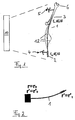
Figur 1- eine Abbildung des Umfeldes eines erfindungsgemäß navigierten Führungsdrahtes; und
- Figur 2
- eine schematische Darstellung des Führungsdrahtes zum Zwecke der theoretischen Erörterung.
- FIG. 1
- an illustration of the environment of a guide wire navigated according to the invention; and
- FIG. 2
- a schematic representation of the guidewire for the purpose of theoretical discussion.
Der in
Das Navigations- und Trackingsystem kann die Position und die Ausrichtung des proximalen Endes 2 ermitteln (r2, dr2/dl). Auch kann die Position und Ausrichtung des Knochens 6 ermittelt werden, und insbesondere die Ausrichtung des inneren Röhrenkanals im Knochen 6. Gesucht wird der Vektor r3, das heißt die Position des distalen Endes 3 des Führungsdrahtes 1.The navigation and tracking system can determine the position and orientation of the proximal end 2 (r 2 , dr 2 / dl). Also, the position and orientation of the
Die Erfindung ist mit den vorher schon beschriebenen Schritten dazu in der Lage, die Einsetztiefe des distalen Endes 3 unter bestimmten Bedingungen zu ermitteln. Hierzu wird entgegen allen bisherigen Ansätzen im Stand der Technik (Magnetnavigation) eine optische Navigation verwendet. Der Handgriff des Führungsdrahtes (distales Ende 2) kann optisch ohne weiteres getrackt werden, und wegen der bekannten Knochenausrichtung (Referenzvorrichtung 5) ist die Ausrichtung der Achse des Röhrenknochens bekannt, in welche der Führungsdraht eingesetzt wird. Dies gestattet es, die Einsetztiefe des Führungsdrahtes auf einem Computermonitor virtuell darzustellen.The invention is able to determine the depth of insertion of the
Die Erfindung berücksichtigt die starke Verbiegung des flexiblen Führungsdrahtes. Dies ist möglich, weil die Ausrichtung des Führungsdrahtes im Bereich der Spitzenposition bekannt ist. Dieses Wissen kann verwendet werden, um die Biegung zu berücksichtigen, die ansonsten nicht erfasst werden könnte. Es sind theoretisch sehr viele Konturen möglich, und in
Es soll hier ausdrücklich darauf hingewiesen werden, dass die vorliegende Erfindung und die vorliegende Offenbarung grundsätzlich das Ermitteln der Position des distalen Ende jedwedes flexiblen länglichen Instrumentes ermöglichen, wenn die hierin beschriebenen Bedingungen eingehalten werden. Insbesondere ist lediglich erforderlich, dass die Ausrichtung im Bereich des distalen Endes bekannt ist (also hier z.B. jedweder Kanal vorhanden ist, dessen Ausrichtung man kennt), da das andere, proximale Ende optisch trackbar ist (in Position und Ausrichtung) und da das flexible Instrument bestimmte körperliche Eigenschaften aufweist, die im Einzelnen noch unten erläutert werden.It is to be expressly understood that the present invention and the present disclosure will, in principle, facilitate determining the position of the distal end of any flexible elongate instrument when the conditions described herein are met. In particular, it is only necessary that the orientation in the region of the distal end is known (ie here, for example, any channel is present whose orientation one knows), since the other, proximal end is optically trackable (in position and orientation) and there the flexible instrument has certain physical characteristics, which will be explained in more detail below.
Das Navigationssystem verfolgt und zeigt also die Einsetztiefe für einen flexiblen medizinischen bzw. chirurgischen Draht in einem Röhrenknochen. Das Navigationssystem besteht, obwohl in
Um die Eindringtiefe eines flexiblen Knochenführungsdrahtes zu tracken und darzustellen müssen die folgenden Bedingungen erfüllt sein:
- a) mit den Begriffen der Elastizitätstheorie ausgedrückt kann der Knochenführungsdraht als steifer bzw. starrer Stab angesehen werden. "Steif" bedeutet, dass die Persistenzlänge des Drahtes (Lp) sehr viel größer ist als die Länge des Drahtes (L). Die Persistenzlänge ist definiert als der Abstand zweier Punkte auf der Kontur des Drahtes, für welche die Auto-Korrelationsfunktion des Tangentenwinkels der Kontur auf
den 1/e-ten Teil abgefallen ist (e = Eulerzahl). Aus der Polymertheorie ist es bekannt, dass die Persistenzlänge geschrieben werden kann als: Lp = YI/kB,T (Y = Young-Modul, I = Flächenträgheitsmoment des Drahtquerschnitts, kB = Bolzmannkonstante; T = Temperatur). Mit typischen Werten für Y, I und T zeigt eine einfache Rechnung, dass Lp >> L ist. - b) Die Länge des Drahtes ist konstant. Da der Young-Modul für das Material des Führungsdrahtes bei ungefähr 100 GPa liegt, kann leicht gezeigt werden, dass die auftretenden Kräfte nur zu relativen Längenänderungen von 0,001 und weniger führen.
- a) expressed in terms of the theory of elasticity, the bone guide wire can be regarded as a rigid rod. "Stiff" means that the persistence length of the wire (Lp) is much greater than the length of the wire (L). The persistence length is defined as the distance between two points on the contour of the wire for which the auto-correlation function of the tangent angle of the contour has dropped to the 1 / e-th part (e = Euler number). It is known from polymer theory that the persistence length can be written as: Lp = YI / k B , T (Y = Young's modulus, I = area moment of inertia of the wire cross section, k B = Bolt man constant, T = temperature). With typical values for Y, I, and T, a simple calculation shows that L p >> L.
- b) The length of the wire is constant. Since the Young's modulus for the guidewire material is about 100 GPa, it can easily be shown that the forces involved only result in relative length changes of 0.001 and less.
Bei einer Berechnungsart kann die Kontur des Drahtes als vektorielle Differentialgleichung der dritten Ordnung beschrieben werden. Um diese Gleichung zu lösen, müssen drei vektorielle Randbedingungen bekannt sein, und diese sind:
- 1) Position des proximalen Drahtendes 2 (am Handgriff)
- 2) Ausrichtung des proximalen Drahtendes;
- 3) Ausrichtung eines Punktes auf dem Draht nahe dem distalen Drahtende.
- 1) Position of the proximal wire end 2 (on the handle)
- 2) alignment of the proximal wire end;
- 3) Alignment of a point on the wire near the distal end of the wire.
Aus 1) bis 3) können die Randbedingungen definiert und die Differentialgleichung gelöst werden und zwar durch numerische Verfahren. Zusammen mit den Bedingungen a) und b) können relevante Informationen über die Eindringtiefe des Drahtes extrahiert und auf der Bilddarstellung des Navigationssystems angezeigt werden. Bildlich gesprochen gestattet es das Wissen um die Ausrichtung des Führungsdrahtes an einer Position in der Nähe seines eingesetzten Endes (distalen Endes) die korrekte Kontur aus der Vielzahl der möglichen Konturen herauszufinden (die möglichen Konturen sind die in
Eine etwas detailliertere Beschreibung der elastizitätstheoretischen Grundlagen ist im Folgenden gegeben, wobei die Gleichungen (1.9) und (1.10) auf die
Das vollständige System der Gleichgewichtsbedingungen eines beliebig gebogenen Stabes lautet: 

wobei F die inneren Spannungskräfte bezeichnet, K sei die auf den Stab wirkende äußere Kraft,
M ist das Drehmoment der inneren Spannungen, die auf die Querschnittsfläche wirken, t ist der Einheitsvektor der Tangente an den Stab, 1 ist die Bogenlänge auf dem Stab, x bezeichnet das Vektorprodukt.The complete system of equilibrium conditions of an arbitrarily bent rod is:
where F denotes the internal stress forces, K is the external force acting on the rod,
M is the torque of the internal stresses acting on the cross-sectional area, t is the unit vector of the tangent to the bar, 1 is the arc length on the bar, x denotes the vector product.
Die x-Komponente von Gleichung (1.2) ist 
Leitet man diese Gleichung zweimal nach der Variablen 1 ab, so erhält man zwei weitere Gleichungen, mit deren Hilfe man Fy und Fz eliminieren kann. Außerdem lassen sich die Ableitungen dFy /dl und dFz /dl mittels (1.1) durch die Komponenten der äußeren Kraft ausdrücken. Man erhält somit für Mx: 
Analoge Gleichungen folgen für My und Mz, wenn man die Vertauschung x→y, y→z, z→x einmal bzw. zweimal vornimmt.Analogous equations follow for M y and M z , if one carries out the permutation x → y, y → z, z → x once or twice.
Wirken die äußeren Kräfte nur auf einzelne isolierte Punkte, so gilt in den Stababschnitten zwischen den Angriffspunkten der äußeren Kräfte K = 0, und damit vereinfacht sich Gleichung (1.4) zu: 
Geht man von der Voraussetzung aus, daß der Querschnitt des Stabes kreisförmig ist, so läßt sich das Drehmoment schreiben als: ![]()
mit E-Elastizitätsmodul des Stabmaterials, 1-Flächenträgheitsmoment des Stabquerschnitts (I = π R4 für einen kreisrunden Querschnitt mit Radius R).Assuming the assumption that the cross section of the rod is circular, the torque can be written as: ![]()
with modulus of elasticity of the rod material, 1-area moment of inertia of the rod cross-section (I = π R 4 for a circular cross-section with radius R).
Einsetzen der x-Komponente von (1.6) in (1.5) ergibt eine DGL der Form: 
Mit ![]()

![]()
Neben g1 gibt es noch zwei weitere DGLn (g2 und g3), die durch die o.g. Indexvertauschung entstehen. Man hat zusammengefaßt ein gekoppeltes DGL-System, in dem die Variable 1 sowie die Funktionen x(1), y(1) und z(1) nicht explizit vorkommen. Demzufolge läßt sich die Ordnung der DGLn um zwei reduzieren auf ein gekoppeltes DGL-System 3. Ordnung bzw. eine Vektordifferentialgleichung 3. Ordnung. Zur Lösung benötigt man drei vektorielle Randbedingungen.In addition to g 1 , there are two more DGLn (g 2 and g 3 ), which are caused by the above-mentioned index interchange. We have summarized a coupled DGL system in which the variable 1 as well as the functions x (1), y (1) and z (1) do not occur explicitly. As a result, the order of the DGLn can be reduced by two to a 3rd order coupled DGL system and a 3rd order vector differential equation, respectively. The solution requires three vectorial boundary conditions.
Der Stab ist einseitig fest eingespannt, d.h. es gilt: 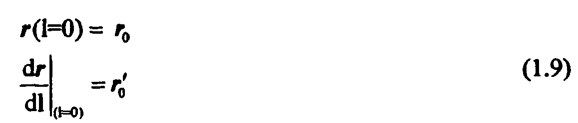
Der Stab bewegt sich an einer Stelle im Raum (r=r 1 ) parallel zu einer "Röhre", d.h. an diesem Punkt ist seine Richtung vorgegeben. Der Punkt auf dem Stab, für den diese Bedingung gilt, ist nicht bekannt, jedoch läßt sich diese Randbedingung 
Claims (8)
- A method for identifying the position of the distal end (3) of a bone guide wire (1), wherein:- the position and orientation of the proximal end (2) of the guide wire (1) is identified with the aid of a medical, optical tracking and navigation system (10) and a reference device (4) on the proximal end (2) of the guide wire;- the orientation of the tubular channel in a bone (6), in which the distal end (3) of the guide wire is located, is identified with the aid of the medical, optical tracking and navigation system (10) and a reference device (5) on the bone (6); and whereinthe position of the distal end (3) of the bone guide wire (1) is identified with the assistance of a computer.(a) by means of the ancillary conditions for the course of the guide wire, which are given by the position and orientation of the proximal end (2) and the orientation of the tubular channel in the bone (6), and(b) by taking into account the physical properties of the guide wire (1),
- The method according to claim 1, wherein the positions are identified with the assistance of a computer using the computer of the tracking and navigation system (10).
- An image support method for using a bone guide wire (1), wherein the position of the distal end (3) of the bone guide wire (1) is identified with the aid of a method according to claim 1 or 2, and wherein this position is outputted on an image output of the tracking and navigation system (10), in relation to the bone arrangement.
- A device for identifying the position of the distal end (3) of a bone guide wire (1), comprising a medical, optical tracking and navigation system (10), a reference device (4) on the proximal end (2) of the guide wire and a reference device (5) on a bone (6) in the tubular channel of which the distal end (3) of the guide wire is located, and comprising a computer, which(a) by means of the ancillary conditions for the course of the guide wire, which are given by the position and orientation of the proximal end (2) and the orientation of the tubular channel in the bone (6), and(b) by taking into account the physical properties of the guide wire (1),identifies the position of the distal end (3) of the bone guide wire (1).
- The device according to claim 4, characterised in that the computer is the computer of the tracking and navigation system (10).
- The device according to claim 4 or 5, characterised in that the tracking and navigation system (10) comprises an image output which outputs the identified position of the distal end in relation to the bone arrangement.
- A program which, when running on a computer or loaded on a computer, causes the computer to carry out a method in accordance with any one of claims 1 to 3.
- A computer program storage medium which comprises a program according to claim 7.
Priority Applications (2)
| Application Number | Priority Date | Filing Date | Title |
|---|---|---|---|
| EP05006219A EP1704825B1 (en) | 2005-03-22 | 2005-03-22 | Guide wire navigation |
| US11/385,251 US8554306B2 (en) | 2005-03-22 | 2006-03-21 | Guide wire navigation |
Applications Claiming Priority (1)
| Application Number | Priority Date | Filing Date | Title |
|---|---|---|---|
| EP05006219A EP1704825B1 (en) | 2005-03-22 | 2005-03-22 | Guide wire navigation |
Publications (2)
| Publication Number | Publication Date |
|---|---|
| EP1704825A1 EP1704825A1 (en) | 2006-09-27 |
| EP1704825B1 true EP1704825B1 (en) | 2012-02-08 |
Family
ID=35457027
Family Applications (1)
| Application Number | Title | Priority Date | Filing Date |
|---|---|---|---|
| EP05006219A Expired - Fee Related EP1704825B1 (en) | 2005-03-22 | 2005-03-22 | Guide wire navigation |
Country Status (1)
| Country | Link |
|---|---|
| EP (1) | EP1704825B1 (en) |
Families Citing this family (3)
| Publication number | Priority date | Publication date | Assignee | Title |
|---|---|---|---|---|
| DE502006005876D1 (en) * | 2006-11-06 | 2010-02-25 | Brainlab Ag | Determining the length of a flexible, long instrument |
| US20110319912A1 (en) * | 2009-03-06 | 2011-12-29 | Ntn Corporation | Navigation system for remote-controlled actuator |
| WO2013098853A2 (en) * | 2011-12-20 | 2013-07-04 | Panchanadikar Vijay | System for accurate guide wire positioning |
Family Cites Families (8)
| Publication number | Priority date | Publication date | Assignee | Title |
|---|---|---|---|---|
| US5274551A (en) * | 1991-11-29 | 1993-12-28 | General Electric Company | Method and apparatus for real-time navigation assist in interventional radiological procedures |
| DE19639615C5 (en) | 1996-09-26 | 2008-11-06 | Brainlab Ag | Reflector referencing system for surgical and medical instruments |
| US6104944A (en) | 1997-11-17 | 2000-08-15 | Martinelli; Michael A. | System and method for navigating a multiple electrode catheter |
| CA2427702A1 (en) * | 2000-11-03 | 2002-05-10 | Synthes (U.S.A.) | Determination of deformations of surgical tools |
| US6718194B2 (en) * | 2000-11-17 | 2004-04-06 | Ge Medical Systems Global Technology Company, Llc | Computer assisted intramedullary rod surgery system with enhanced features |
| DE10118570B4 (en) * | 2001-01-10 | 2004-06-03 | Aesculap Ag & Co. Kg | Surgical device |
| EP1319366A1 (en) | 2001-12-14 | 2003-06-18 | BrainLAB AG | Magnetic navigation for a catheter |
| EP1413257B1 (en) * | 2002-10-25 | 2005-02-23 | BrainLAB AG | Device for positioning an element, for example in the spine |
-
2005
- 2005-03-22 EP EP05006219A patent/EP1704825B1/en not_active Expired - Fee Related
Also Published As
| Publication number | Publication date |
|---|---|
| EP1704825A1 (en) | 2006-09-27 |
Similar Documents
| Publication | Publication Date | Title |
|---|---|---|
| EP1593350B1 (en) | Tracking of intramedullary pin | |
| EP1319366A1 (en) | Magnetic navigation for a catheter | |
| EP1872735B1 (en) | Method for automatic identification of instruments during medical navigation | |
| DE69922980T2 (en) | METHOD AND DEVICE FOR POSITIONING A DEVICE IN A BODY | |
| DE102007059599B4 (en) | Device for a medical intervention and method of operation for a device for a medical intervention | |
| DE19914455B4 (en) | Method for determining the movement of an organ or therapeutic area of a patient and a system suitable for this purpose | |
| DE102005007893B4 (en) | Method for determining the position of an instrument with an X-ray system | |
| EP2575662B1 (en) | Method for moving an instrument arm of a laparoscopy robot into a predeterminable relative position with respect to a trocar | |
| EP2135575A1 (en) | Instrument alignment method with free reference | |
| EP3261564B1 (en) | Set of medical instruments, and method | |
| EP1857070A1 (en) | Contactless medical registration with distance measurement | |
| EP3287093B1 (en) | Set of medical instruments and method | |
| EP3500152B1 (en) | Detection system for automatically detecting surgical instruments | |
| DE102007013407A1 (en) | Method and device for providing correction information | |
| DE102005044405A1 (en) | Method of producing an image of a medical instrument at least partly inserted into an object or patient under examination using vectors | |
| DE102005059804A1 (en) | Navigation of inserted medical instrument in a patient, e.g. a catheter, uses initial three dimensional image of the target zone to give a number of two-dimensional images for comparison with fluoroscopic images taken during the operation | |
| DE10240727A1 (en) | Imaging system and method for optimizing an x-ray image | |
| DE19807884C2 (en) | Method for calibrating a recording device for determining spatial coordinates of anatomical target objects and device for carrying out the method | |
| DE202011110755U1 (en) | Navigation attachment for optical devices in medicine and device for displaying image data | |
| DE102004044285A1 (en) | System and method for determining the position of an elastic instrument used in a position tracking system | |
| DE19530013C1 (en) | Correcting position of target e.g. tumour in target region of radiation treatment device | |
| DE10029737B4 (en) | Navigation of a medical instrument | |
| EP1704825B1 (en) | Guide wire navigation | |
| DE102019200786A1 (en) | Medical imaging device, method for assisting medical personnel, computer program product and computer readable storage medium | |
| DE10141406B4 (en) | Method and device for detecting the three-dimensional position of an examination instrument inserted in a body region |
Legal Events
| Date | Code | Title | Description |
|---|---|---|---|
| PUAI | Public reference made under article 153(3) epc to a published international application that has entered the european phase |
Free format text: ORIGINAL CODE: 0009012 |
|
| 17P | Request for examination filed |
Effective date: 20050322 |
|
| AK | Designated contracting states |
Kind code of ref document: A1 Designated state(s): AT BE BG CH CY CZ DE DK EE ES FI FR GB GR HU IE IS IT LI LT LU MC NL PL PT RO SE SI SK TR |
|
| AX | Request for extension of the european patent |
Extension state: AL BA HR LV MK YU |
|
| AKX | Designation fees paid |
Designated state(s): DE FR GB IT |
|
| 17Q | First examination report despatched |
Effective date: 20071011 |
|
| APBN | Date of receipt of notice of appeal recorded |
Free format text: ORIGINAL CODE: EPIDOSNNOA2E |
|
| APBR | Date of receipt of statement of grounds of appeal recorded |
Free format text: ORIGINAL CODE: EPIDOSNNOA3E |
|
| APAF | Appeal reference modified |
Free format text: ORIGINAL CODE: EPIDOSCREFNE |
|
| RAP1 | Party data changed (applicant data changed or rights of an application transferred) |
Owner name: BRAINLAB AG |
|
| APBT | Appeal procedure closed |
Free format text: ORIGINAL CODE: EPIDOSNNOA9E |
|
| GRAP | Despatch of communication of intention to grant a patent |
Free format text: ORIGINAL CODE: EPIDOSNIGR1 |
|
| GRAS | Grant fee paid |
Free format text: ORIGINAL CODE: EPIDOSNIGR3 |
|
| GRAA | (expected) grant |
Free format text: ORIGINAL CODE: 0009210 |
|
| AK | Designated contracting states |
Kind code of ref document: B1 Designated state(s): DE FR GB IT |
|
| REG | Reference to a national code |
Ref country code: GB Ref legal event code: FG4D Free format text: NOT ENGLISH |
|
| REG | Reference to a national code |
Ref country code: DE Ref legal event code: R096 Ref document number: 502005012422 Country of ref document: DE Effective date: 20120412 |
|
| PG25 | Lapsed in a contracting state [announced via postgrant information from national office to epo] |
Ref country code: IT Free format text: LAPSE BECAUSE OF FAILURE TO SUBMIT A TRANSLATION OF THE DESCRIPTION OR TO PAY THE FEE WITHIN THE PRESCRIBED TIME-LIMIT Effective date: 20120208 |
|
| PLBE | No opposition filed within time limit |
Free format text: ORIGINAL CODE: 0009261 |
|
| STAA | Information on the status of an ep patent application or granted ep patent |
Free format text: STATUS: NO OPPOSITION FILED WITHIN TIME LIMIT |
|
| 26N | No opposition filed |
Effective date: 20121109 |
|
| REG | Reference to a national code |
Ref country code: DE Ref legal event code: R097 Ref document number: 502005012422 Country of ref document: DE Effective date: 20121109 |
|
| REG | Reference to a national code |
Ref country code: DE Ref legal event code: R082 Ref document number: 502005012422 Country of ref document: DE Representative=s name: SCHWABE SANDMAIR MARX, DE |
|
| REG | Reference to a national code |
Ref country code: DE Ref legal event code: R081 Ref document number: 502005012422 Country of ref document: DE Owner name: BRAINLAB AG, DE Free format text: FORMER OWNER: BRAINLAB AG, 85622 FELDKIRCHEN, DE Effective date: 20131104 Ref country code: DE Ref legal event code: R081 Ref document number: 502005012422 Country of ref document: DE Owner name: BRAINLAB AG, DE Free format text: FORMER OWNER: BRAINLAB AG, 85551 KIRCHHEIM, DE Effective date: 20120216 Ref country code: DE Ref legal event code: R082 Ref document number: 502005012422 Country of ref document: DE Representative=s name: SCHWABE SANDMAIR MARX, DE Effective date: 20131104 Ref country code: DE Ref legal event code: R082 Ref document number: 502005012422 Country of ref document: DE Representative=s name: SCHWABE SANDMAIR MARX PATENTANWAELTE RECHTSANW, DE Effective date: 20131104 |
|
| REG | Reference to a national code |
Ref country code: FR Ref legal event code: PLFP Year of fee payment: 12 |
|
| PGFP | Annual fee paid to national office [announced via postgrant information from national office to epo] |
Ref country code: GB Payment date: 20160321 Year of fee payment: 12 Ref country code: FR Payment date: 20160321 Year of fee payment: 12 |
|
| PGFP | Annual fee paid to national office [announced via postgrant information from national office to epo] |
Ref country code: DE Payment date: 20160330 Year of fee payment: 12 |
|
| REG | Reference to a national code |
Ref country code: DE Ref legal event code: R082 Ref document number: 502005012422 Country of ref document: DE Representative=s name: SCHWABE SANDMAIR MARX PATENTANWAELTE RECHTSANW, DE Ref country code: DE Ref legal event code: R081 Ref document number: 502005012422 Country of ref document: DE Owner name: BRAINLAB AG, DE Free format text: FORMER OWNER: BRAINLAB AG, 85622 FELDKIRCHEN, DE Ref country code: DE Ref legal event code: R082 Ref document number: 502005012422 Country of ref document: DE Representative=s name: SSM SANDMAIR PATENTANWAELTE RECHTSANWALT PARTN, DE |
|
| REG | Reference to a national code |
Ref country code: FR Ref legal event code: CA Effective date: 20170706 |
|
| REG | Reference to a national code |
Ref country code: DE Ref legal event code: R119 Ref document number: 502005012422 Country of ref document: DE |
|
| GBPC | Gb: european patent ceased through non-payment of renewal fee |
Effective date: 20170322 |
|
| REG | Reference to a national code |
Ref country code: FR Ref legal event code: ST Effective date: 20171130 |
|
| PG25 | Lapsed in a contracting state [announced via postgrant information from national office to epo] |
Ref country code: FR Free format text: LAPSE BECAUSE OF NON-PAYMENT OF DUE FEES Effective date: 20170331 Ref country code: DE Free format text: LAPSE BECAUSE OF NON-PAYMENT OF DUE FEES Effective date: 20171003 |
|
| PG25 | Lapsed in a contracting state [announced via postgrant information from national office to epo] |
Ref country code: GB Free format text: LAPSE BECAUSE OF NON-PAYMENT OF DUE FEES Effective date: 20170322 |