EP1704287B1 - Noppenbahn - Google Patents
Noppenbahn Download PDFInfo
- Publication number
- EP1704287B1 EP1704287B1 EP05700944.1A EP05700944A EP1704287B1 EP 1704287 B1 EP1704287 B1 EP 1704287B1 EP 05700944 A EP05700944 A EP 05700944A EP 1704287 B1 EP1704287 B1 EP 1704287B1
- Authority
- EP
- European Patent Office
- Prior art keywords
- dimpled sheet
- dimpled
- base body
- sheet
- composite panel
- Prior art date
- Legal status (The legal status is an assumption and is not a legal conclusion. Google has not performed a legal analysis and makes no representation as to the accuracy of the status listed.)
- Expired - Lifetime
Links
- 239000012528 membrane Substances 0.000 title 1
- 239000002131 composite material Substances 0.000 claims description 43
- 238000009413 insulation Methods 0.000 claims description 26
- 238000012546 transfer Methods 0.000 claims description 18
- 239000000049 pigment Substances 0.000 claims description 13
- 229920003023 plastic Polymers 0.000 claims description 13
- 239000004033 plastic Substances 0.000 claims description 11
- 239000011248 coating agent Substances 0.000 claims description 9
- 238000000576 coating method Methods 0.000 claims description 9
- GWEVSGVZZGPLCZ-UHFFFAOYSA-N Titan oxide Chemical compound O=[Ti]=O GWEVSGVZZGPLCZ-UHFFFAOYSA-N 0.000 claims description 8
- 239000000463 material Substances 0.000 claims description 8
- 229910052751 metal Inorganic materials 0.000 claims description 8
- 239000002184 metal Substances 0.000 claims description 8
- 239000011093 chipboard Substances 0.000 claims description 7
- 238000000034 method Methods 0.000 claims description 7
- 230000005670 electromagnetic radiation Effects 0.000 claims description 5
- 239000011120 plywood Substances 0.000 claims description 5
- 238000002310 reflectometry Methods 0.000 claims description 4
- 239000004408 titanium dioxide Substances 0.000 claims description 4
- 239000011888 foil Substances 0.000 claims description 3
- 239000002985 plastic film Substances 0.000 claims description 3
- 230000008878 coupling Effects 0.000 claims description 2
- 238000010168 coupling process Methods 0.000 claims description 2
- 238000005859 coupling reaction Methods 0.000 claims description 2
- 229920006255 plastic film Polymers 0.000 claims description 2
- 230000005855 radiation Effects 0.000 claims 1
- 238000004519 manufacturing process Methods 0.000 description 8
- 238000011161 development Methods 0.000 description 7
- 230000018109 developmental process Effects 0.000 description 7
- 239000004567 concrete Substances 0.000 description 6
- 229910052782 aluminium Inorganic materials 0.000 description 4
- XAGFODPZIPBFFR-UHFFFAOYSA-N aluminium Chemical compound [Al] XAGFODPZIPBFFR-UHFFFAOYSA-N 0.000 description 4
- 230000001681 protective effect Effects 0.000 description 4
- 239000011810 insulating material Substances 0.000 description 3
- 230000000295 complement effect Effects 0.000 description 2
- 238000010276 construction Methods 0.000 description 2
- 230000000875 corresponding effect Effects 0.000 description 2
- 230000000694 effects Effects 0.000 description 2
- 238000001125 extrusion Methods 0.000 description 2
- 239000012774 insulation material Substances 0.000 description 2
- 239000007788 liquid Substances 0.000 description 2
- SRQWKWUBLKLIDX-UHFFFAOYSA-N [Ti].O1C=COC=C1 Chemical compound [Ti].O1C=COC=C1 SRQWKWUBLKLIDX-UHFFFAOYSA-N 0.000 description 1
- 206010000496 acne Diseases 0.000 description 1
- 230000002411 adverse Effects 0.000 description 1
- 230000004888 barrier function Effects 0.000 description 1
- 239000004566 building material Substances 0.000 description 1
- 230000001427 coherent effect Effects 0.000 description 1
- 239000012141 concentrate Substances 0.000 description 1
- 238000013016 damping Methods 0.000 description 1
- 230000001419 dependent effect Effects 0.000 description 1
- 238000013461 design Methods 0.000 description 1
- 238000009826 distribution Methods 0.000 description 1
- 229920002457 flexible plastic Polymers 0.000 description 1
- 238000010438 heat treatment Methods 0.000 description 1
- 229920001903 high density polyethylene Polymers 0.000 description 1
- 239000004700 high-density polyethylene Substances 0.000 description 1
- 238000007373 indentation Methods 0.000 description 1
- 238000009434 installation Methods 0.000 description 1
- 238000005304 joining Methods 0.000 description 1
- 239000004922 lacquer Substances 0.000 description 1
- 239000002557 mineral fiber Substances 0.000 description 1
- 230000008092 positive effect Effects 0.000 description 1
- 238000012805 post-processing Methods 0.000 description 1
- 238000012545 processing Methods 0.000 description 1
- 238000007789 sealing Methods 0.000 description 1
- 239000002689 soil Substances 0.000 description 1
- 125000006850 spacer group Chemical group 0.000 description 1
- 238000007740 vapor deposition Methods 0.000 description 1
- 238000003466 welding Methods 0.000 description 1
Images
Classifications
-
- E—FIXED CONSTRUCTIONS
- E04—BUILDING
- E04D—ROOF COVERINGS; SKY-LIGHTS; GUTTERS; ROOF-WORKING TOOLS
- E04D3/00—Roof covering by making use of flat or curved slabs or stiff sheets
- E04D3/35—Roofing slabs or stiff sheets comprising two or more layers, e.g. for insulation
- E04D3/357—Roofing slabs or stiff sheets comprising two or more layers, e.g. for insulation comprising hollow cavities
-
- E—FIXED CONSTRUCTIONS
- E04—BUILDING
- E04D—ROOF COVERINGS; SKY-LIGHTS; GUTTERS; ROOF-WORKING TOOLS
- E04D13/00—Special arrangements or devices in connection with roof coverings; Protection against birds; Roof drainage ; Sky-lights
- E04D13/16—Insulating devices or arrangements in so far as the roof covering is concerned, e.g. characterised by the material or composition of the roof insulating material or its integration in the roof structure
- E04D13/1606—Insulation of the roof covering characterised by its integration in the roof structure
-
- E—FIXED CONSTRUCTIONS
- E04—BUILDING
- E04F—FINISHING WORK ON BUILDINGS, e.g. STAIRS, FLOORS
- E04F15/00—Flooring
- E04F15/18—Separately-laid insulating layers; Other additional insulating measures; Floating floors
-
- E—FIXED CONSTRUCTIONS
- E04—BUILDING
- E04F—FINISHING WORK ON BUILDINGS, e.g. STAIRS, FLOORS
- E04F15/00—Flooring
- E04F15/18—Separately-laid insulating layers; Other additional insulating measures; Floating floors
- E04F15/182—Underlayers coated with adhesive or mortar to receive the flooring
-
- E—FIXED CONSTRUCTIONS
- E04—BUILDING
- E04F—FINISHING WORK ON BUILDINGS, e.g. STAIRS, FLOORS
- E04F15/00—Flooring
- E04F15/18—Separately-laid insulating layers; Other additional insulating measures; Floating floors
- E04F15/185—Underlayers in the form of studded or ribbed plates
-
- E—FIXED CONSTRUCTIONS
- E02—HYDRAULIC ENGINEERING; FOUNDATIONS; SOIL SHIFTING
- E02D—FOUNDATIONS; EXCAVATIONS; EMBANKMENTS; UNDERGROUND OR UNDERWATER STRUCTURES
- E02D31/00—Protective arrangements for foundations or foundation structures; Ground foundation measures for protecting the soil or the subsoil water, e.g. preventing or counteracting oil pollution
- E02D31/02—Protective arrangements for foundations or foundation structures; Ground foundation measures for protecting the soil or the subsoil water, e.g. preventing or counteracting oil pollution against ground humidity or ground water
Definitions
- the invention relates to a dimpled sheet according to the preamble of claim 1, a composite panel with such a dimpled sheet and a method for thermal insulation of a building according to the preamble of claim 13.
- Known dimpled sheets of the type mentioned are usually used as a foundation wall protection, where they are located between the soil and the outside of the foundation wall or an insulation used there and also meet a drainage function.
- the currently used dimpled sheets have no influence on the thermal insulation of the buildings, since their heat transfer resistance is extremely low, in particular due to the low reflection properties of the surfaces.
- current brown or black dimpled sheets only have a reflectivity of 2-5%.
- Known composite panels of the type mentioned are preferably used abroad as floorboards, where they are used between heated living spaces and an unheated surface, such as a concrete floor of a basement or a ground floor housing.
- the structure of the composite plate for example, has a base body made of a chipboard or a plywood plate and a knobbed sheet attached to the base body.
- the dimpled sheet serves both as a vapor barrier against moisture, the u. U. could rise from the concrete floor, as well as the elastic support of the floor plate, so that a certain damping effect is achieved.
- a panel material which has a plurality of frusto-conical projections with a polygon basic shape and, in combination with an upper and lower plate, serves as a core element for a composite component.
- the projections in particular have a hexagonal basic shape and are hollow from the inside.
- the panel material is used in conjunction with the top and bottom panels as a composite panel for use in the interior of buildings.
- the insulating material is formed by two flexible plastic films, which have bulges in the form of pockets, which may be provided on the inside and / or outside with a heat-reflecting aluminum coating. After joining the two foils to the insulating material by welding, a composite arrangement with completely closed pockets is created, which is intended to bring about thermal insulation. From this reference, the features of the preamble of claim 1 are known.
- a thin magnetic wave absorbing plate material which is formed by two layered structures.
- a layer structure is formed by a metallically reflecting layer and another layer structure by an electromagnetic wave absorbing layer.
- A1 is a composite material known, which consists of three layers and can be used for decorative purposes, for example in building walls or for thermal insulation.
- a middle layer is made of transparent plastic material with pigments and a titanium dioxin layer and is covered by a respective upper and lower layer of transparent plastic material.
- the protective plate for building exterior walls or floors known.
- the protective plate is made of a plastic material and has a plurality of knob-like bulges, which are characterized by crater-like indentations are transformed.
- the protective plate is preferably usable as a protective plate between a bottom layer of chipboard and a cast layer, for example, to form a drainage.
- From the DE 21 49 851 A1 is a flat insulation, especially for buildings, tents or the like. known from at least three interconnected layers.
- the middle layer has a plurality of spacers, which may be knob-like and each form closed cavities.
- the cavities are filled with gas to completely exclude heat conduction between the two outer layers.
- the invention is therefore an object of the invention to provide a simple structure as possible Noppenbahn with a high heat transfer resistance and to improve the thermal insulation of a composite panel of the type mentioned while maintaining the basic structure of known composite panels.
- the invention is also based on the object, a method for thermal insulation of a building, in particular for the thermal insulation of a floor to provide.
- the invention solves the problem by a dimpled sheet according to the features of claim 1, by a composite panel according to claim 9 and by a method according to claim 13.
- Advantageous developments of the invention are described in the dependent claims.
- Characteristic of the dimpled sheet according to the invention is a surface which has a high degree of reflection.
- a high reflectance is understood to mean a reflection of the surface of more than 20%.
- the dimpled sheet may in principle have hollow nubs formed on one or both sides of a plane, with dimpled sheets having nubs formed on one side being used to produce the composite panel according to the invention.
- the dimpled sheet is fastened with its side facing away from the dimples on a base body.
- the dimpled sheet is formed from infrared radiation-reflecting, pigmented plastic.
- Kunststoffnoppenbahn is particularly notable by their simple and inexpensive production as well as their formability and flexibility. These properties also allow a particularly inexpensive and trouble-free production of a composite panel.
- the overall heat transfer resistance of the dimpled sheet as well as the composite panel is composed of the heat transfer resistance to radiant heat and the heat transfer resistance to convection heat.
- the total heat transfer resistance is calculated from the reciprocal of the sum of the heat transfer resistances to convection and radiant heat. Due to the high reflectivity of the surface of the dimpled sheet, the heat transfer resistance to radiant heat and thus the total heat transfer resistance can be influenced.
- the broad field of application of the dimpled sheet according to the invention for example for building a floor, for sealing the building walls in or above the ground or for insulation in the roof area makes it possible to provide the buildings with a particularly high thermal insulation, which leads to a significant reduction in heating costs contributes.
- the high reflectance of the surface of the dimpled sheet significantly improves their heat transfer resistance to radiant heat, it is necessary that air layers adjacent to the surface of the dimpled sheet.
- the use of the dimpled sheet according to the invention for the construction of the composite panel according to the invention ensures the existence of sufficient layers of air in each case on the surface of the dimpled sheet according to the distribution of dimples and free surfaces.
- the surface of the dimpled sheet has a reflectance of more than 0.2 (20% reflection), in particular more than 0.35 (35% reflection) or 0.5 (50% reflection).
- the heat transfer resistance of the dimpled sheet with respect to dark dimpled sheets having a reflectance of 0.02 to 0.05 is at least 1.2 times higher.
- the heat transfer resistance of the composite panel is about 1.4 and 1.7 times the value of dark dimpled sheets, respectively.
- the dimpled sheet has a smooth surface.
- the reflectance of the dimpled sheet is increased in a complementary manner, whereby an additional increase of the heat transfer resistance to radiant heat is achieved, so that further improves the overall heat transfer resistance of the composite panel.
- the surface of the dimpled sheet has a reflective coating.
- the coating of the dimpled sheet can be applied to the surface of the dimpled sheet in a mechanical manner, by vapor deposition or in any other way.
- the coating may also be designed such that it is suitable for reflecting or at least attenuating electromagnetic radiation.
- the attenuation is at least 5 dB, preferably at least 10 dB, particularly preferably at least 15 dB.
- This embodiment of the inventive dimpled sheet whose range of application is increased in a complementary manner, the increasing importance of the shielding of living and working spaces against unwanted electromagnetic radiation is taken into account.
- the coating can also be produced, for example, by applying a pigment-containing liquid to the surface of the dimpled sheet, the pigments remaining on the surface of the dimpled sheet after the liquid has flowed off, giving the latter its reflective properties.
- the plastic contains color pigments, in particular titanium dioxide or metal pigments, for example aluminum pigments.
- the pigments can already be mixed into a corresponding plastic melt prior to extruding the dimpled sheet so that post-processing of the dimpled sheet subsequent to the extrusion can be dispensed with in order to increase the degree of reflection.
- the titanium dioxide, but in particular the metal pigments, for example the aluminum pigments are characterized by their property of enabling the production of a dimpled sheet with a high degree of reflection even in low concentrations in the plastic melt.
- the positive properties of the Kunststoffnoppenbahn, such as flexibility, impact resistance, strength, etc. are not adversely affected by the titanium dioxide.
- the dimpled sheet according to the invention can in principle be used alone, for example for thermal insulation in the floor, roof or wall area.
- the dimpled sheet can also be combined with other materials or building materials, such as seals or thermal insulation, whereby the production of a correspondingly prefabricated product is possible, which then has the advantages of the dimpled sheet according to the invention and of one or more products.
- the base body is designed as chipboard or plywood.
- Chipboard and plywood boards are characterized, inter alia, by their low-cost production, by their simple processing and by their particularly good insulation properties, so that the corresponding properties of the composite panel according to the invention can be further improved. Furthermore, this development allows the
- thermal insulation such as, for example, mineral fiber boards
- chipboard or plywood as a base body
- thermal insulation such as, for example, mineral fiber boards
- These can also be used in the roof area or for the insulation of the building walls.
- a metal foil or metal-coated plastic film is arranged on the side of the base body facing the dimpled sheet or between the dimpled sheet and the base body.
- the base body has two pairs of parallel edge, wherein two adjacent edges with coupling elements in the form of a groove and the other two are provided with a spring which fits into the groove.
- Characteristic of the inventive method for thermal insulation of a building, in particular for thermal insulation of a floor is that first a dimpled sheet with a reflectance of more than 0.2 (20% reflection), in particular more than 0.35 (35% reflection) or 0, 5 (50% reflection) is arranged on the surface to be insulated, in particular on the floor and then a base body is applied to the dimpled sheet.
- This method allows in a particularly simple manner, the construction of a thermal insulation on site, for example, directly on the site.
- the laying of the dimpled sheet is particularly easy because of its flexibility and good processability.
- Kunststoffnoppenbahn When using a Kunststoffnoppenbahn to produce a thermal insulation usually present in the rolled state Kunststoffnoppenbahn must be unrolled only on the surface to be insulated. Subsequently, the base body is mounted on the dimpled sheet.
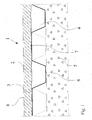
- Fig. 1 shows a dimpled sheet 3 and a base body 2, which together form a composite plate 1, which is shown in a mounting position as a floor plate on a concrete base 5.
- the composite panel 1 has a two-layer structure consisting of the dimpled sheet 3 and the base body 2.
- the dimpled sheet 3 is made of plastic and has unilaterally formed, diagonally extending knobs 4 with substantially parallel to Noppenbahnebene end faces 6, which are in contact with the concrete base 5.
- both sides of the dimpled sheet 3 are bordered by extensive air layers on the dimpled sheet 3.
- An upper side 8 of the main body 2 forms a tread surface of the composite panel 1.
- the plastic of the dimpled sheet 3 has a reflectance of 0.2 (20% reflection).
- the main body 2 is formed of a chipboard.
- a coating, not shown here, of the dimpled sheet with a lacquer containing metal pigments effects a shielding against electromagnetic radiation of 17 dB in the range from 200 kHz to 10 GHz.
- the production can be carried out by extrusion and continuous vacuum deep drawing of 97% HDPE (eg Stamyland HD 7625, Stamylan Germany) with 3% aluminum pigment concentrate (eg Mastersafe 10203, Eckhart), so that a basis weight of 600 g / m 2 is achieved.
Landscapes
- Engineering & Computer Science (AREA)
- Architecture (AREA)
- Civil Engineering (AREA)
- Structural Engineering (AREA)
- Building Environments (AREA)
- Floor Finish (AREA)
- Laminated Bodies (AREA)
- Extrusion Moulding Of Plastics Or The Like (AREA)
Description
- Die Erfindung betrifft eine Noppenbahn nach dem Oberbegriff des Anspruchs 1, eine Verbundplatte mit einer derartigen Noppenbahn und ein Verfahren zur Wärmedämmung eines Gebäudes nach dem Oberbegriff des Anspruchs 13.
- Bekannte Noppenbahnen der eingangs genannten Art werden üblicherweise als Grundmauerschutz verwendet, wobei sie zwischen dem Erdreich und der Außenseite der Grundmauer bzw. einer dort verwendeten Dämmung angeordnet werden und dabei zudem eine Drainagefunktion erfüllen.
- Auf die Wärmedämmung der Gebäude haben die derzeit verwendeten Noppenbahnen jedoch keinen Einfluss, da deren Wärmeübergangswiderstand insbesondere aufgrund der niedrigen Reflexionseigenschaften der Oberflächen äußerst gering ist. So weisen derzeit gängige braune oder schwarze Noppenbahnen lediglich einen Reflexionsgrad von 2-5% auf.
- Bekannte Verbundplatten der eingangs genannten Art werden vorzugsweise im Ausland als Fußbodenplatten verwendet, wobei sie zwischen beheizten Wohnräumen und einem unbeheizten Untergrund, beispielsweise einer Betonsohle eines Kellerraums oder eines ebenerdig errichteten Wohnraums eingesetzt werden.
- Der Aufbau der Verbundplatte weist dabei beispielsweise einen Grundkörper aus einer Spanplatte oder einer Sperrholzplatte und eine auf dem Grundkörper angebrachte Noppenbahn auf. Die Noppenbahn dient dabei sowohl als Dampfsperre gegenüber Feuchtigkeit, die u. U. von der Betonsohle aufsteigen könnte, als auch zur elastischen Lagerung der Fußbodenplatte, so daß eine gewisse Dämpfungswirkung erreicht wird.
- Der Einsatz derartige Verbundplatten weist jedoch den Nachteil auf, dass trotz der Hohlräume zwischen der Noppenbahn und der Betonsohle sowie in den Noppen selbst eine nur unzureichende Wärmedämmung erreicht wird. Bekannte Lösungen dieses Problems sehen die Verwendung einer zusätzlichen Dämmstoffschicht zwischen der Noppenbahn und dem Grundkörper vor. Dadurch kann die Wärmedämmung zwar insgesamt verbessert werden, aufgrund der erforderlichen Dicke der Dämmstoffschicht geht jedoch Raumhöhe verloren, was insbesondere bei der Verwendung einer derartigen Verbundplatte beim Altbaubestand problematisch ist. Ferner gestaltet sich die Herstellung derartiger Verbundplatten mit einer Dämmstoffschicht als sehr aufwendig und nicht zuletzt aufgrund des zusätzlich benötigten Dämmmaterials als äußerst teuer.
- Aus der
US 5,399,406 ist ein Paneelmaterial bekannt, welches eine Mehrzahl von kegelstumpfförmigen Vorsprüngen mit einer Vieleckgrundform aufweist und im Verbund mit einer Ober- und Unterplatte als Kernelement für ein Verbundbauteil dient. Die Vorsprünge weisen insbesondere eine Sechseckgrundform auf und sind von innen hohl. Das Paneelmaterial dient im Verbund mit der Ober- und Unterplatte als Verbundpaneel zum Einsatz im Innenbereich von Gebäuden. - Aus der
GB 2 079 415 A - Aus der
JP 2003-332782 A - Aus der
US 2003/0148093 A1 ist ein Verbundmaterial bekannt, welches aus drei Schichten besteht und für dekorative Zwecke z.B. bei Gebäudewänden oder auch zur Wärmedämmung einsetzbar ist. Eine mittlere Schicht besteht aus transparentem Kunststoffmaterial mit Pigmenten und einer Titandioxinschicht und wird durch jeweils eine obere und untere Schicht aus transparentem Kunststoffmaterial umfasst. - Aus der
WO 82/03099 A - Aus der
DE 21 49 851 A1 ist eine flächige Isolierung, insbesondere für Bauwerke, Zelte o.dgl. aus mindestens drei miteinander verbundenen Schichten bekannt. Die mittlere Schicht weist eine Vielzahl von Distanzgliedern auf, die noppenartig sein können und jeweils abgeschlossene Hohlräume bilden. Die Hohlräume sind mit Gas gefüllt, um eine Wärmeleitung zwischen den beiden äußeren Schichten vollständig auszuschließen. - Der Erfindung liegt daher die Aufgabe zugrunde, eine möglichst einfach aufgebaute Noppenbahn mit einem hohen Wärmeübergangswiderstand bereitzustellen sowie die Wärmedämmung einer Verbundplatte der eingangs genannten Art unter Beibehaltung des prinzipiellen Aufbaus bekannter Verbundplatten zu verbessern. Der Erfindung liegt ferner die Aufgabe zugrunde, ein Verfahren zur Wärmedämmung eines Gebäudes, insbesondere zur Wärmedämmung eines Fußbodens, bereitzustellen.
- Die Erfindung löst die Aufgabe durch eine Noppenbahn gemäß den Merkmalen des Anspruchs 1, durch eine Verbundplatte gemäß Anspruch 9 sowie durch ein Verfahren gemäß Anspruch 13. Vorteilhafte Weiterbildungen der Erfindung sind in den abhängigen Ansprüchen beschrieben.
- Kennzeichnend für die erfindungsgemäße Noppenbahn ist eine Oberfläche, die einen hohen Reflexionsgrad aufweist. Im Rahmen der Erfindung wird unter einem hohen Reflexionsgrad dabei eine Reflexion der Oberfläche von mehr als 20 % verstanden. Die Noppenbahn kann dabei grundsätzlich einseitig oder beidseitig einer Ebene ausgeformte hohle Noppen aufweisen, wobei zur Herstellung der erfindungsgemäßen Verbundplatte vorzugsweise Noppenbahnen mit einseitig ausgeformten Noppen verwendet werden. Die Noppenbahn ist dabei mit ihrer den Noppen abgewandten Seite auf einem Grundkörper befestigt.
- Erfindungsgemäß ist die Noppenbahn aus Infrarotstrahlung reflektierendem, pigmentierten Kunststoff gebildet. Eine derartige Kunststoffnoppenbahn zeichnet sich insbesondere durch ihre einfache und kostengünstige Herstellung sowie durch ihre Formbarkeit und Flexibilität aus. Diese Eigenschaften ermöglichen auch eine besonders preiswerte und problemlose Produktion einer Verbundplatte.
- Der Gesamtwärmeübergangswiderstand der Noppenbahn als auch der Verbundplatte setzt sich zusammen aus dem Wärmeübergangswiderstand gegen Strahlungswärme und dem Wärmeübergangswiderstand gegen Konvektionswärme. Mathematisch errechnet sich der Gesamtwärmeübergangswiderstand aus dem Kehrwert der Summe der Wärmeübergangswiderstände gegen Konvektions- und Strahlungswärme. Durch den hohen Reflexionsgrad der Oberfläche der Noppenbahn kann der Wärmeübergangswiderstand gegen Strahlungswärme und damit der Gesamtwärmeübergangswiderstand beeinflusst werden.
- Der breite Einsatzbereich der erfindungsgemäßen Noppenbahn, bspw. zum Aufbau eines Fußbodens, zur Abdichtung der Gebäudewände im oder oberhalb des Erdreichs oder zur Isolierung im Dachbereich ermöglicht es dabei, die Gebäude insgesamt mit einer besonders hohen Wärmedämmung zu versehen, die zu einer deutlichen Reduzierung der Heizkosten beiträgt.
- Damit der hohe Reflexionsgrad der Oberfläche der Noppenbahn deren Wärmeübergangswiderstand gegen Strahlungswärme maßgeblich verbessert, ist es erforderlich, dass Luftschichten an die Oberfläche der Noppenbahn angrenzen. Die Verwendung der erfindungsgemäßen Noppenbahn zum Aufbau der erfindungsgemäßen Verbundplatte gewährleistet das Bestehen ausreichender Luftschichten jeweils an der Oberfläche der Noppenbahn entsprechend der Verteilung von Noppen und freien Flächen.
- Im Falle der bevorzugten Verwendung einer Noppenbahn mit einseitig ausgeformten Noppen grenzen in einer Gebrauchslage der Verbundplatte, beispielsweise bei der Verwendung als Fußbodenplatte, Luftschichten an weite Teile der Noppenbahn. So befindet sich eine Luftschicht in den zwischen der Noppenbahn und dem Grundkörper gebildeten Hohlkammern der Noppen. Eine weitere labyrinthartig zusammenhängende Luftschicht besteht zwischen den Noppen. Diese umfangreichen Bereiche gewährleisten, dass sich der Gesamtwärmeübergangswiderstand der Verbundplatte durch den hohen Reflexionsgrad der Noppenbahn wesentlich erhöht.
- Nach einer vorteilhaften Weiterbildung der Erfindung weist die Oberfläche der Noppenbahn einen Reflexionsgrad von mehr als 0,2 (20% Reflexion), insbesondere mehr als 0,35 (35% Reflexion) oder 0,5 (50% Reflexion) auf. Bereits bei einem Reflexionsgrad von 0,2 liegt der Wärmeübergangswiderstand der Noppenbahn gegenüber dunklen Noppenbahnen mit einem Reflexionsgrad von 0,02 bis 0,05 mindestens um den Faktor 1,2 höher. Bei einem Reflexionsgrad von 0,35 oder 0,5 entspricht der Wärmeübergangswiderstand der Verbundplatte etwa dem 1,4- bzw. 1,7-fachen des Wertes für dunkle Noppenbahnen. Somit kann gewährleistet werden, dass ohne die Verwendung zusätzlicher Dämmmaterialien eine hohe Wärmedämmung erreicht wird bzw. die Dämmleistung erhöht wird.
- Gemäß einer weiteren Ausgestaltung der Erfindung weist die Noppenbahn eine glatte Oberfläche auf. Durch eine derartige Ausbildung der Oberflächenstruktur der Noppenbahn wird der Reflexionsgrad der Noppenbahn in ergänzender Weise erhöht, wodurch eine zusätzliche Steigerung des Wärmeübergangswiderstand gegen Strahlungswärme erreicht wird, so dass sich der Gesamtwärmeübergangswiderstand der Verbundplatte weiter verbessert.
- Die Möglichkeiten, die Noppenbahn mit einem hohen Reflexionsgrad auszubilden, sind vielfältig. Nach einer Weiterbildung der Erfindung weist die Oberfläche der Noppenbahn eine reflektierende Beschichtung auf. Die Beschichtung der Noppenbahn kann in Abhängigkeit von der Art der Beschichtung in mechanischer Weise, durch Aufdampfen oder in sonstiger Weise auf die Oberfläche der Noppenbahn aufgebracht werden.
- Die Beschichtung kann ferner derart ausgebildet sein, dass sie dazu geeignet ist, elektromagnetische Strahlung zu reflektieren oder zumindest zu dämpfen. Die Dämpfung beträgt dabei mindestens 5 dB, vorzugsweise mindestens 10 dB, besonders bevorzugt mindestens 15 dB. Durch diese Ausgestaltung der erfindungemäßen Noppenbahn wird deren Einsatzbereich in ergänzender Weise gesteigert, wobei der zunehmenden Bedeutung an der Abschirmung von Wohn- und Arbeitsräumen gegen unerwünschte elektromagnetische Strahlung Rechnung getragen wird.
- Die Beschichtung kann beispielsweise auch durch Aufbringen einer pigmenthaltigen Flüssigkeit auf die Oberfläche der Noppenbahn erzeugt werden, wobei die Pigmente nach dem Abfließen der Flüssigkeit auf der Oberfläche der Noppenbahn verbleiben und dieser ihre reflektierenden Eigenschaften verleihen.
- Nach der Erfindung enthält der Kunststoff Farbpigmente, insbesondere Titandioxid oder Metallpigmente, bspw. Aluminiumpigmente. Die Pigmente können bereits vor dem Extrudieren der Noppenbahn in eine entsprechende Kunststoffschmelze eingemischt sein, so dass auf eine sich an die Extrusion anschließende Nachbearbeitung der Noppenbahn zur Steigerung des Reflexionsgrads verzichtet werden kann. Das Titandioxid, insbesondere aber die Metallpigmente, bspw. die Aluminiumpigmente zeichnen sich dabei durch ihre Eigenschaft aus, bereits in geringen Konzentrationen in der Kunststoffschmelze die Herstellung einer Noppenbahn mit einem hohen Reflexionsgrad zu ermöglichen. Die positiven Eigenschaften der Kunststoffnoppenbahn, wie Flexibilität, Schlagzähigkeit, Festigkeit etc. werden dabei durch das Titandioxid nicht negativ beeinflusst.
- Die erfindungsgemäße Noppenbahn kann grundsätzlich alleine, bspw. zur Wärmedämmung im Fußboden-, Dach- oder Wandbereich eingesetzt werden. Darüber hinaus kann die Noppenbahn auch mit anderen Materialien oder Baustoffen, wie Abdichtungen oder Wärmedämmungen kombiniert werden, wobei auch die Herstellung eines entsprechend vorgefertigten Produkts möglich ist, welches dann die Vorteile der erfindungsgemäßen Noppenbahn und des oder der weiteren Produkte aufweist.
- Bei der Verwendung der Noppenbahn zur Herstellung des Verbundkörpers kann der Grundkörper entsprechend dem Einsatzgebiet der Verbundplatte frei gewählt werden. Nach einer vorteilhaften Weiterbildung der Erfindung ist der Grundkörper als Spanplatte oder Sperrholzplatte ausgebildet.
- Span- und Sperrholzplatten zeichnen sich u. a. durch ihre preiswerte Herstellung, durch ihre einfache Verarbeitung sowie durch ihre besonders guten Dämmungseigenschaften aus, so dass die entsprechenden Eigenschaften der erfindungsgemäßen Verbundplatte weiter verbessert werden können. Ferner erlaubt diese Weiterbildung der
- Erfindung eine besonders kostengünstige Herstellung der erfindungsgemäßen Verbundplatte.
- Neben der Verwendung von Span- oder Sperrholzplatten als Grundkörper können auch bekannte Wärmedämmungen, wie bspw. Mineralfaserplatten, dazu verwendet werden, um eine Verbundplatte herzustellen. Diese können auch im Dachbereich oder zur Dämmung der Gebäudewände verwendet werden.
- Nach einer weiteren Ausgestaltung der Verbundplatte ist eine Metallfolie oder metallbedampfte Kunststoff-Folie auf der der Noppenbahn zugewandten Seite des Grundkörpers oder zwischen der Noppenbahn und dem Grundkörper angeordnet. Diese besonders einfache Weiterbildung verbessert in ergänzender Weise den Wärmeübergangswiderstand des Verbundkörpers.
- Nach einer Weiterbildung der Verbundplatte weist der Grundkörper zwei Paar parallele Kante auf, wobei zwei benachbarte Kanten mit Kupplungselementen in Form einer Nut und die anderen beiden mit einer Feder versehen sind, die in die Nut passt. Diese Weiterbildung bietet den Vorteil, dass die Verlegung der Verbundplatte erleichtert wird und die verwendeten Verbundplatten untereinander formschlüssig miteinander verbunden werden können, was zu einer Stabilitätssteigerung des Verbunds aus mehreren Verbundplatten führt.
- Kennzeichnend für das erfindungsgemäße Verfahren zur Wärmedämmung eines Gebäudes, insbesondere zur Wärmedämmung eines Fußbodens ist, dass zuerst eine Noppenbahn mit einem Reflexionsgrad von mehr als 0,2 (20% Reflexion), insbesondere mehr als 0,35 (35% Reflexion) oder 0,5 (50% Reflexion) auf die zu dämmende Oberfläche, insbesondere auf dem Fußboden angeordnet wird und anschließend ein Grundkörper auf die Noppenbahn aufgebracht wird.
- Dieses Verfahren ermöglicht in besonders einfacher Weise den Aufbau einer Wärmedämmung vor Ort, beispielsweise direkt auf der Baustelle. Die Verlegung der Noppenbahn gestaltet sich dabei aufgrund ihrer Flexibilität und guten Verarbeitbarkeit besonders einfach.
- Bei der Verwendung einer Kunststoffnoppenbahn muss zur Herstellung einer Wärmedämmung die üblicherweise im aufgerollten Zustand vorliegende Kunststoffnoppenbahn lediglich auf der zu dämmenden Oberfläche abgerollt werden. Anschließend wird der Grundkörper auf der Noppenbahn befestigt.
- Ein Ausführungsbeispiel der Erfindung wird nachstehend mit Bezug auf die Zeichnung erläutert. In der Zeichnung zeigt:
- Fig. 1
- einen Querschnitt durch eine auf einer Betonsohle angeordnete Verbundplatte.
-
Fig. 1 zeigt eine Noppenbahn 3 und einen Grundkörper 2, die zusammen eine Verbundplatte 1 bilden, die in einer Einbaulage als Fußbodenplatte auf einer Betonsohle 5 dargestellt ist. Die Verbundplatte 1 weist einen zweischichtigen Aufbau bestehend aus der Noppenbahn 3 und dem Grundkörper 2 auf. - Die Noppenbahn 3 besteht aus Kunststoff und weist einseitig ausgeformte, diagonal verlaufende Noppen 4 mit im wesentlichen parallel zur Noppenbahnebene verlaufenden Stirnseiten 6 auf, die mit der Betonsohle 5 in Kontakt stehen. In der Einbaulage der Verbundplatte 1 grenzen beiderseits der Noppenbahn 3 umfangreiche Luftschichten an die Noppenbahn 3. Mit ihrer den Noppen 4 abgewandten Seite ist die Noppenbahn 3 mit einer Unterseite 7 des Grundkörpers 2 verklebt. Eine Oberseite 8 des Grundkörpers 2 bildet eine Trittfläche der Verbundplatte 1.
- Zur Erreichung eines hohen Wärmeübergangswiderstands der Verbundplatte 1 weist der Kunststoff der Noppenbahn 3 einen Reflexionsgrad von 0,2 (20% Reflexion) auf. Der Grundkörper 2 ist aus einer Spanplatte gebildet.
- Eine hier nicht dargestellte Beschichtung der Noppenbahn mit einem Metallpigmente enthaltenden Lack, bewirkt eine Abschirmung gegen elektromagnetische Strahlung von 17 dB im Bereich von 200 kHz bis 10 GHz.
- Nachfolgend werden beispielhaft zwei Verfahren zur Herstellung einer Noppenbahn mit einer Infrarot-Strahlung reflektierenden Oberfläche dargestellt.
- Die Herstellung kann durch Extrusion und kontinuierliches Vakuum-Tiefziehen von 97% HDPE (z. B. Stamyland HD 7625, Fa. Stamylan Deutschland) mit 3% Aluminiumpigment-Konzentrat (z. B. Mastersafe 10203, Fa. Eckhart) erfolgen, so dass ein Flächengewicht von 600 g/m2 erreicht wird. Der Reflexionsgrad einer derart hergestellten Noppenbahn gemessen im Infrarotbereich von 2-20 µm mit einer Ulbricht Kugel beträgt 22%.
Claims (13)
- Noppenbahn (3) zur Dämmung von Gebäudewänden und Fußböden, wobei die Noppenbahn (3) einseitig oder beidseitig einer Ebene ausgeformte hohle Noppen (4) sowie zur Steigerung des Wärmeübergangswiderstands eine einen Reflexionsgrad von mehr als 0,2 (20 % Reflexion) aufweisende Oberfläche aufweist und aus einem Infrarotstrahlung reflektierenden Kunststoff gebildet ist,
dadurch gekennzeichnet,
dass im Kunststoff Farbpigmente für den von mehr als 0,2 hohen Reflexionsgrad eingemischt sind. - Noppenbahn (3) nach Anspruch 1, dadurch gekennzeichnet, dass die Oberfläche einen Reflexionsgrad von mehr als 0,35 (35 % Reflexion) oder 0,5 (50 % Reflexion) aufweist.
- Noppenbahn (3) nach Anspruch 1 oder 2, dadurch gekennzeichnet, dass diese eine glatte Oberfläche aufweist.
- Noppenbahn (3) nach einem der vorhergehenden Ansprüche, dadurch gekennzeichnet, dass die Oberfläche derart ausgebildet ist, dass sie elektromagnetische Strahlung reflektiert oder dämpft.
- Noppenbahn (3) nach einem der vorhergehenden Ansprüche, dadurch gekennzeichnet, dass die Oberfläche die elektromagnetische Strahlung um mindestens 5 dB, vorzugsweise mindestens 10 dB, besonders bevorzugt mindestens 15 dB dämpft.
- Noppenbahn (3) nach einem oder mehreren der vorhergehenden Ansprüche; dadurch gekennzeichnet, dass die Oberfläche eine reflektierende Beschichtung aufweist.
- Noppenbahn (3) nach einem oder mehreren der vorhergehenden Ansprüche, dadurch gekennzeichnet, dass der Kunststoff Titandioxid oder Metallpigmente enthält.
- Noppenbahn (3) nach einem oder mehreren der vorhergehenden Ansprüche, dadurch gekennzeichnet, dass die Kunststoffoberfläche der Noppenbahn (3) eine Metallbeschichtung aufweist.
- Verbundplatte (1), insbesondere eine hohlraumbildende Fußbodenplatte mit- einem Grundkörper (2) und- einer auf dem Grundkörper (2) angeordneten Noppenbahn (3),dadurch gekennzeichnet, dass die Noppenbahn (3) entsprechend einem oder mehreren der Ansprüche 1 bis 8 ausgebildet ist.
- Verbundplatte (1) nach Anspruch 9, dadurch gekennzeichnet, dass der Grundkörper (2) als Spanplatte oder Sperrholzplatte ausgebildet ist.
- Verbundplatte (1) nach einem oder mehreren der vorhergehenden Ansprüche, dadurch gekennzeichnet, dass eine Metallfolie oder metallbedampfte Kunststoff-Folie auf der der Noppenbahn (3) zugewandten Seite des Grundkörpers (2) angeordnet ist.
- Verbundptatte (1) nach einem oder mehreren der vorhergehenden Ansprüche, dadurch gekennzeichnet, dass der Grundkörper (2) zwei Paar parallele Kanten aufweist, wobei zwei benachbarte Kanten mit Kupplungselementen in Form einer Nut und die anderen beiden mit einer Feder versehen sind, die in die Nut passt.
- Verfahren zur Wärmedämmung eines Gebäudes, insbesondere zur Wärmedämmung eines Fußbodens, dadurch gekennzeichnet, dass- zuerst eine Noppenbahn (3) entsprechend einem oder mehreren der Ansprüche 1 bis 8, mit einem Reflexionsgrad von mehr als 20 %, insbesondere mehr als 35 % oder 50 % auf die zu dämmende Oberfläche, insbesondere auf dem Fußboden angeordnet wird und- anschließend ein Grundkörper (2) auf die Noppenbahn (3) aufgebracht wird.
Priority Applications (1)
| Application Number | Priority Date | Filing Date | Title |
|---|---|---|---|
| PL05700944T PL1704287T3 (pl) | 2004-01-14 | 2005-01-14 | Folia kubełkowa |
Applications Claiming Priority (2)
| Application Number | Priority Date | Filing Date | Title |
|---|---|---|---|
| DE102004002115A DE102004002115B4 (de) | 2004-01-14 | 2004-01-14 | Noppenbahn, Verbundplatte und Verfahren zur Herstellung einer Noppenbahn |
| PCT/EP2005/000350 WO2005068742A1 (de) | 2004-01-14 | 2005-01-14 | Noppenbahn |
Publications (2)
| Publication Number | Publication Date |
|---|---|
| EP1704287A1 EP1704287A1 (de) | 2006-09-27 |
| EP1704287B1 true EP1704287B1 (de) | 2015-12-23 |
Family
ID=34778062
Family Applications (1)
| Application Number | Title | Priority Date | Filing Date |
|---|---|---|---|
| EP05700944.1A Expired - Lifetime EP1704287B1 (de) | 2004-01-14 | 2005-01-14 | Noppenbahn |
Country Status (8)
| Country | Link |
|---|---|
| US (1) | US20080271400A1 (de) |
| EP (1) | EP1704287B1 (de) |
| CA (1) | CA2553338C (de) |
| DE (1) | DE102004002115B4 (de) |
| EA (1) | EA008404B1 (de) |
| HU (1) | HUE027177T2 (de) |
| PL (1) | PL1704287T3 (de) |
| WO (1) | WO2005068742A1 (de) |
Families Citing this family (12)
| Publication number | Priority date | Publication date | Assignee | Title |
|---|---|---|---|---|
| DE202005013697U1 (de) | 2005-08-30 | 2007-01-11 | Isola A/S | Bodenbelag |
| FR2912490B1 (fr) * | 2007-02-09 | 2010-10-29 | Alcan Rhenalu | Panneau composite metallique et procede de fabrication |
| US8490338B2 (en) * | 2010-02-26 | 2013-07-23 | Henkel Corporation | Self adhering window flashing tape with multi-directional drainage plane |
| CH704894A2 (de) * | 2011-05-04 | 2012-11-15 | H D S Technology Ag | Raumbegrenzungsaufbau, Verfahren zum Herstellen desselben und Element dafür. |
| CN103195104B (zh) * | 2012-01-10 | 2016-04-27 | 邹新建 | 一种在建筑结构防水部位采用防排组合的构造方法 |
| US9834158B2 (en) * | 2013-11-29 | 2017-12-05 | Cary Paik | Acoustic flooring assembly |
| JP2017210742A (ja) * | 2016-05-24 | 2017-11-30 | 積水樹脂株式会社 | 床材 |
| RU169894U1 (ru) * | 2016-10-13 | 2017-04-05 | Константин Петрович Фролов | Строительная панель |
| US10385566B2 (en) * | 2017-09-20 | 2019-08-20 | Carl Arthur Carlson | Structural insulated panel framing system with a radiant barrier |
| WO2019089182A1 (en) * | 2017-11-01 | 2019-05-09 | Paik Cary | Acoustic flooring assembly |
| US10563412B1 (en) * | 2018-11-30 | 2020-02-18 | Cary Paik | Acoustic flooring assembly |
| CN111811021A (zh) * | 2019-10-30 | 2020-10-23 | 香河容大建筑工程有限公司 | 一种eps聚苯模块与电热地膜装配的温度控制系统 |
Citations (2)
| Publication number | Priority date | Publication date | Assignee | Title |
|---|---|---|---|---|
| BE849809A (fr) * | 1975-12-25 | 1977-04-15 | Procede de confection de feuilles stratifiees convenant entre autres pour le drainage du sol | |
| GB2079415A (en) * | 1980-07-02 | 1982-01-20 | Wilson Michael J Bolton Ltd | Thermal insulation |
Family Cites Families (21)
| Publication number | Priority date | Publication date | Assignee | Title |
|---|---|---|---|---|
| US2330941A (en) * | 1940-02-23 | 1943-10-05 | Keasbey & Mattison Company | Insulation |
| DE2149851A1 (de) * | 1971-10-06 | 1973-04-12 | Franz Kerner | Flaechige isolierung |
| JPS5312968A (en) * | 1976-07-21 | 1978-02-06 | Nissan Motor | Process for making packing material of corrugated cardboard |
| DE8015172U1 (de) * | 1980-06-07 | 1980-11-20 | Kawasaki, Tetsuo, 4044 Kaarst | Isolierbahn fuer den hoch- und tiefbau |
| NO148041C (no) * | 1981-03-11 | 1987-06-10 | Platon As | Beskyttelsesplate, saerlig for grunnmur eller gulv paa grunn |
| US5271980A (en) * | 1991-07-19 | 1993-12-21 | Bell Dennis J | Flexible evacuated insulating panel |
| DE4213068A1 (de) * | 1992-04-21 | 1993-10-28 | Huels Troisdorf | System und Verfahren zum Relining von Kanalrohrabschnitten |
| JPH06200595A (ja) * | 1993-01-05 | 1994-07-19 | Takenaka Komuten Co Ltd | 防水層保護シートとアスファルト防水層の構造 |
| US6421970B1 (en) * | 1995-03-07 | 2002-07-23 | Perstorp Flooring Ab | Flooring panel or wall panel and use thereof |
| US5918436A (en) * | 1997-07-08 | 1999-07-06 | Alderman; Robert J. | Radiant barrier facing material |
| DE10201087A1 (de) * | 2001-01-15 | 2002-07-25 | Li & Co Gmbh Muestair | Elastischer Bodenbelag |
| GB0109156D0 (en) * | 2001-04-12 | 2001-05-30 | British Sisalkraft | Cavity wall lining sheet |
| US6811852B2 (en) * | 2001-10-02 | 2004-11-02 | Robert J. Alderman | Reflective heat insulation |
| US6557313B1 (en) * | 2002-01-04 | 2003-05-06 | Robert J. Alderman | Blanket insulation with reflective sheet and air space |
| DE10160569A1 (de) * | 2001-12-10 | 2003-06-26 | Bayer Ag | Mehrschichtiges Erzeugnis |
| US20030124315A1 (en) * | 2001-12-28 | 2003-07-03 | Grochoski Chester F. | Reflective, lateral heat distributing insulation blanket |
| US6857238B2 (en) * | 2002-06-28 | 2005-02-22 | J. A. Effect, Llc | Heat insulator with air gap and reflector |
| JP2003332782A (ja) * | 2002-05-09 | 2003-11-21 | Nippon Tokushu Toryo Co Ltd | 電磁波吸収シート |
| US6997981B1 (en) * | 2002-05-20 | 2006-02-14 | Jds Uniphase Corporation | Thermal control interface coatings and pigments |
| ATE378802T1 (de) * | 2003-08-14 | 2007-11-15 | Doerken Ewald Ag | Reflexionsschicht |
| DE102007035851A1 (de) * | 2007-01-13 | 2008-08-14 | Vacuum Walls Ag | Vakuum-Isolationspaneel und Herstellungsverfahren dafür |
-
2004
- 2004-01-14 DE DE102004002115A patent/DE102004002115B4/de not_active Expired - Fee Related
-
2005
- 2005-01-14 PL PL05700944T patent/PL1704287T3/pl unknown
- 2005-01-14 CA CA2553338A patent/CA2553338C/en not_active Expired - Lifetime
- 2005-01-14 EP EP05700944.1A patent/EP1704287B1/de not_active Expired - Lifetime
- 2005-01-14 HU HUE05700944A patent/HUE027177T2/en unknown
- 2005-01-14 WO PCT/EP2005/000350 patent/WO2005068742A1/de not_active Ceased
- 2005-01-14 US US10/585,770 patent/US20080271400A1/en not_active Abandoned
- 2005-01-14 EA EA200601312A patent/EA008404B1/ru not_active IP Right Cessation
Patent Citations (2)
| Publication number | Priority date | Publication date | Assignee | Title |
|---|---|---|---|---|
| BE849809A (fr) * | 1975-12-25 | 1977-04-15 | Procede de confection de feuilles stratifiees convenant entre autres pour le drainage du sol | |
| GB2079415A (en) * | 1980-07-02 | 1982-01-20 | Wilson Michael J Bolton Ltd | Thermal insulation |
Also Published As
| Publication number | Publication date |
|---|---|
| DE102004002115B4 (de) | 2006-08-17 |
| HUE027177T2 (en) | 2016-10-28 |
| DE102004002115A1 (de) | 2005-08-18 |
| CA2553338C (en) | 2013-12-17 |
| EA200601312A1 (ru) | 2006-10-27 |
| US20080271400A1 (en) | 2008-11-06 |
| EA008404B1 (ru) | 2007-04-27 |
| PL1704287T3 (pl) | 2016-06-30 |
| WO2005068742A1 (de) | 2005-07-28 |
| EP1704287A1 (de) | 2006-09-27 |
| CA2553338A1 (en) | 2005-07-28 |
Similar Documents
| Publication | Publication Date | Title |
|---|---|---|
| DE19805348A1 (de) | Abstandhalterprofil für Isolierscheibeneinheit | |
| WO2008141689A1 (de) | Vakuum-isolationspaneel und herstellungsverfahren dafür | |
| EP2855793B1 (de) | Dacheindeckungselement | |
| DE102008064572A1 (de) | Mehrschichtige Wärmedämmplatte und Verfahren zum Aufbau einer Wärmedämmfassade | |
| DE102004002115B4 (de) | Noppenbahn, Verbundplatte und Verfahren zur Herstellung einer Noppenbahn | |
| EP2726680B1 (de) | FASSADENKONSTRUKTION ZUR WÄRMEDÄMMUNG UND VERKLEIDUNG VON GEBÄUDEAUßENWÄNDEN SOWIE VERFAHREN ZUR HERSTELLUNG EINER SOLCHEN FASSADENKONSTRUKTION | |
| DE10147409B4 (de) | Wärmeisolierendes, tragfähiges Bauelement und Verfahren zu seiner Herstellung | |
| DE3401868A1 (de) | Fussbodenheizrohr-verlegeplatte | |
| EP1566264B1 (de) | Wärmedämmkörper | |
| DE20280280U1 (de) | Dekoratives Metallaminat | |
| DE69609981T2 (de) | Paneele | |
| EP2402522A2 (de) | Bau- und/oder Wärmedämmplatte sowie Wärmedämmverbundsystem mit entsprechender Platte | |
| DE2535850C3 (de) | Plattenförmiges Bauteil, insbesondere Fassadenelement | |
| EP1099807B1 (de) | Fassadenelement | |
| DE102011109122A1 (de) | Mehrschichtiges Bauelement | |
| EP2203611A2 (de) | Eps-schaumstoffplatte mit reflektierender oberfläche | |
| EP3208402B1 (de) | Anordnung mit einem dach- oder fassadenelement in gestalt eines sandwichartig aufgebauten dämmpaneels und mit einem fensterelement | |
| DE3021537A1 (de) | Isolierung fuer den hoch- und tiefbau | |
| DE19756718B4 (de) | Fassadenplatte und Fassade für eine Gebäudewand | |
| EP0959190A2 (de) | Wärmedämmelement | |
| AT512652B1 (de) | Wärmedämmplatte | |
| EP0936063A2 (de) | Wärmedämmendes Verbundbauelement | |
| DE19707575C2 (de) | Vorgefertigtes Kelleraußenwandelement | |
| DE202009010591U1 (de) | Thermisch wirksames Fassadenelement für Gebäudewände sowie System zur thermischen Isolierung einer Gebäudewand | |
| EP2678490A1 (de) | Tragfähiges oder tragendes leichtbauelement |
Legal Events
| Date | Code | Title | Description |
|---|---|---|---|
| PUAI | Public reference made under article 153(3) epc to a published international application that has entered the european phase |
Free format text: ORIGINAL CODE: 0009012 |
|
| 17P | Request for examination filed |
Effective date: 20060704 |
|
| AK | Designated contracting states |
Kind code of ref document: A1 Designated state(s): AT BE BG CH CY CZ DE DK EE ES FI FR GB GR HU IE IS IT LI LT LU MC NL PL PT RO SE SI SK TR |
|
| DAX | Request for extension of the european patent (deleted) | ||
| 17Q | First examination report despatched |
Effective date: 20110926 |
|
| GRAP | Despatch of communication of intention to grant a patent |
Free format text: ORIGINAL CODE: EPIDOSNIGR1 |
|
| INTG | Intention to grant announced |
Effective date: 20150929 |
|
| RIC1 | Information provided on ipc code assigned before grant |
Ipc: E04D 3/35 20060101ALI20150918BHEP Ipc: E04D 13/16 20060101ALI20150918BHEP Ipc: E04F 15/18 20060101ALI20150918BHEP Ipc: E04C 2/296 20060101AFI20150918BHEP Ipc: E02D 31/02 20060101ALI20150918BHEP |
|
| GRAS | Grant fee paid |
Free format text: ORIGINAL CODE: EPIDOSNIGR3 |
|
| GRAA | (expected) grant |
Free format text: ORIGINAL CODE: 0009210 |
|
| AK | Designated contracting states |
Kind code of ref document: B1 Designated state(s): AT BE BG CH CY CZ DE DK EE ES FI FR GB GR HU IE IS IT LI LT LU MC NL PL PT RO SE SI SK TR |
|
| REG | Reference to a national code |
Ref country code: GB Ref legal event code: FG4D Free format text: NOT ENGLISH |
|
| REG | Reference to a national code |
Ref country code: CH Ref legal event code: EP |
|
| REG | Reference to a national code |
Ref country code: IE Ref legal event code: FG4D Free format text: LANGUAGE OF EP DOCUMENT: GERMAN |
|
| REG | Reference to a national code |
Ref country code: AT Ref legal event code: REF Ref document number: 766638 Country of ref document: AT Kind code of ref document: T Effective date: 20160115 |
|
| REG | Reference to a national code |
Ref country code: FR Ref legal event code: PLFP Year of fee payment: 12 |
|
| REG | Reference to a national code |
Ref country code: DE Ref legal event code: R096 Ref document number: 502005015048 Country of ref document: DE |
|
| PGFP | Annual fee paid to national office [announced via postgrant information from national office to epo] |
Ref country code: NL Payment date: 20160120 Year of fee payment: 12 Ref country code: LU Payment date: 20160125 Year of fee payment: 12 |
|
| REG | Reference to a national code |
Ref country code: NL Ref legal event code: FP |
|
| REG | Reference to a national code |
Ref country code: LT Ref legal event code: MG4D |
|
| PG25 | Lapsed in a contracting state [announced via postgrant information from national office to epo] |
Ref country code: LT Free format text: LAPSE BECAUSE OF FAILURE TO SUBMIT A TRANSLATION OF THE DESCRIPTION OR TO PAY THE FEE WITHIN THE PRESCRIBED TIME-LIMIT Effective date: 20151223 |
|
| PG25 | Lapsed in a contracting state [announced via postgrant information from national office to epo] |
Ref country code: SE Free format text: LAPSE BECAUSE OF FAILURE TO SUBMIT A TRANSLATION OF THE DESCRIPTION OR TO PAY THE FEE WITHIN THE PRESCRIBED TIME-LIMIT Effective date: 20151223 Ref country code: GR Free format text: LAPSE BECAUSE OF FAILURE TO SUBMIT A TRANSLATION OF THE DESCRIPTION OR TO PAY THE FEE WITHIN THE PRESCRIBED TIME-LIMIT Effective date: 20160324 |
|
| PG25 | Lapsed in a contracting state [announced via postgrant information from national office to epo] |
Ref country code: ES Free format text: LAPSE BECAUSE OF FAILURE TO SUBMIT A TRANSLATION OF THE DESCRIPTION OR TO PAY THE FEE WITHIN THE PRESCRIBED TIME-LIMIT Effective date: 20151223 Ref country code: CZ Free format text: LAPSE BECAUSE OF FAILURE TO SUBMIT A TRANSLATION OF THE DESCRIPTION OR TO PAY THE FEE WITHIN THE PRESCRIBED TIME-LIMIT Effective date: 20151223 |
|
| PG25 | Lapsed in a contracting state [announced via postgrant information from national office to epo] |
Ref country code: SK Free format text: LAPSE BECAUSE OF FAILURE TO SUBMIT A TRANSLATION OF THE DESCRIPTION OR TO PAY THE FEE WITHIN THE PRESCRIBED TIME-LIMIT Effective date: 20151223 Ref country code: IS Free format text: LAPSE BECAUSE OF FAILURE TO SUBMIT A TRANSLATION OF THE DESCRIPTION OR TO PAY THE FEE WITHIN THE PRESCRIBED TIME-LIMIT Effective date: 20160423 Ref country code: EE Free format text: LAPSE BECAUSE OF FAILURE TO SUBMIT A TRANSLATION OF THE DESCRIPTION OR TO PAY THE FEE WITHIN THE PRESCRIBED TIME-LIMIT Effective date: 20151223 Ref country code: RO Free format text: LAPSE BECAUSE OF FAILURE TO SUBMIT A TRANSLATION OF THE DESCRIPTION OR TO PAY THE FEE WITHIN THE PRESCRIBED TIME-LIMIT Effective date: 20151223 Ref country code: PT Free format text: LAPSE BECAUSE OF FAILURE TO SUBMIT A TRANSLATION OF THE DESCRIPTION OR TO PAY THE FEE WITHIN THE PRESCRIBED TIME-LIMIT Effective date: 20160426 |
|
| REG | Reference to a national code |
Ref country code: DE Ref legal event code: R097 Ref document number: 502005015048 Country of ref document: DE |
|
| PG25 | Lapsed in a contracting state [announced via postgrant information from national office to epo] |
Ref country code: MC Free format text: LAPSE BECAUSE OF FAILURE TO SUBMIT A TRANSLATION OF THE DESCRIPTION OR TO PAY THE FEE WITHIN THE PRESCRIBED TIME-LIMIT Effective date: 20151223 |
|
| PLBE | No opposition filed within time limit |
Free format text: ORIGINAL CODE: 0009261 |
|
| REG | Reference to a national code |
Ref country code: HU Ref legal event code: AG4A Ref document number: E027177 Country of ref document: HU |
|
| STAA | Information on the status of an ep patent application or granted ep patent |
Free format text: STATUS: NO OPPOSITION FILED WITHIN TIME LIMIT |
|
| PG25 | Lapsed in a contracting state [announced via postgrant information from national office to epo] |
Ref country code: DK Free format text: LAPSE BECAUSE OF FAILURE TO SUBMIT A TRANSLATION OF THE DESCRIPTION OR TO PAY THE FEE WITHIN THE PRESCRIBED TIME-LIMIT Effective date: 20151223 |
|
| REG | Reference to a national code |
Ref country code: IE Ref legal event code: MM4A |
|
| 26N | No opposition filed |
Effective date: 20160926 |
|
| REG | Reference to a national code |
Ref country code: FR Ref legal event code: PLFP Year of fee payment: 13 |
|
| PG25 | Lapsed in a contracting state [announced via postgrant information from national office to epo] |
Ref country code: IE Free format text: LAPSE BECAUSE OF NON-PAYMENT OF DUE FEES Effective date: 20160114 |
|
| PG25 | Lapsed in a contracting state [announced via postgrant information from national office to epo] |
Ref country code: SI Free format text: LAPSE BECAUSE OF FAILURE TO SUBMIT A TRANSLATION OF THE DESCRIPTION OR TO PAY THE FEE WITHIN THE PRESCRIBED TIME-LIMIT Effective date: 20151223 |
|
| REG | Reference to a national code |
Ref country code: NL Ref legal event code: MM Effective date: 20170201 |
|
| PG25 | Lapsed in a contracting state [announced via postgrant information from national office to epo] |
Ref country code: LU Free format text: LAPSE BECAUSE OF NON-PAYMENT OF DUE FEES Effective date: 20170114 Ref country code: NL Free format text: LAPSE BECAUSE OF NON-PAYMENT OF DUE FEES Effective date: 20170201 |
|
| REG | Reference to a national code |
Ref country code: FR Ref legal event code: PLFP Year of fee payment: 14 |
|
| PG25 | Lapsed in a contracting state [announced via postgrant information from national office to epo] |
Ref country code: CY Free format text: LAPSE BECAUSE OF FAILURE TO SUBMIT A TRANSLATION OF THE DESCRIPTION OR TO PAY THE FEE WITHIN THE PRESCRIBED TIME-LIMIT Effective date: 20151223 |
|
| PG25 | Lapsed in a contracting state [announced via postgrant information from national office to epo] |
Ref country code: BG Free format text: LAPSE BECAUSE OF FAILURE TO SUBMIT A TRANSLATION OF THE DESCRIPTION OR TO PAY THE FEE WITHIN THE PRESCRIBED TIME-LIMIT Effective date: 20151223 |
|
| PGFP | Annual fee paid to national office [announced via postgrant information from national office to epo] |
Ref country code: FI Payment date: 20200122 Year of fee payment: 16 Ref country code: GB Payment date: 20200123 Year of fee payment: 16 Ref country code: AT Payment date: 20200122 Year of fee payment: 16 Ref country code: IT Payment date: 20200131 Year of fee payment: 16 |
|
| REG | Reference to a national code |
Ref country code: FI Ref legal event code: MAE |
|
| REG | Reference to a national code |
Ref country code: AT Ref legal event code: MM01 Ref document number: 766638 Country of ref document: AT Kind code of ref document: T Effective date: 20210114 |
|
| GBPC | Gb: european patent ceased through non-payment of renewal fee |
Effective date: 20210114 |
|
| PG25 | Lapsed in a contracting state [announced via postgrant information from national office to epo] |
Ref country code: AT Free format text: LAPSE BECAUSE OF NON-PAYMENT OF DUE FEES Effective date: 20210114 Ref country code: FI Free format text: LAPSE BECAUSE OF NON-PAYMENT OF DUE FEES Effective date: 20210114 |
|
| PG25 | Lapsed in a contracting state [announced via postgrant information from national office to epo] |
Ref country code: GB Free format text: LAPSE BECAUSE OF NON-PAYMENT OF DUE FEES Effective date: 20210114 |
|
| PG25 | Lapsed in a contracting state [announced via postgrant information from national office to epo] |
Ref country code: IT Free format text: LAPSE BECAUSE OF NON-PAYMENT OF DUE FEES Effective date: 20210114 |
|
| PGFP | Annual fee paid to national office [announced via postgrant information from national office to epo] |
Ref country code: HU Payment date: 20220116 Year of fee payment: 18 |
|
| PGFP | Annual fee paid to national office [announced via postgrant information from national office to epo] |
Ref country code: TR Payment date: 20220112 Year of fee payment: 18 |
|
| PG25 | Lapsed in a contracting state [announced via postgrant information from national office to epo] |
Ref country code: HU Free format text: LAPSE BECAUSE OF NON-PAYMENT OF DUE FEES Effective date: 20230115 |
|
| PGFP | Annual fee paid to national office [announced via postgrant information from national office to epo] |
Ref country code: DE Payment date: 20240123 Year of fee payment: 20 Ref country code: CH Payment date: 20240202 Year of fee payment: 20 |
|
| PGFP | Annual fee paid to national office [announced via postgrant information from national office to epo] |
Ref country code: PL Payment date: 20240104 Year of fee payment: 20 Ref country code: FR Payment date: 20240124 Year of fee payment: 20 Ref country code: BE Payment date: 20240119 Year of fee payment: 20 |
|
| REG | Reference to a national code |
Ref country code: DE Ref legal event code: R071 Ref document number: 502005015048 Country of ref document: DE |
|
| REG | Reference to a national code |
Ref country code: CH Ref legal event code: PL |
|
| REG | Reference to a national code |
Ref country code: BE Ref legal event code: MK Effective date: 20250114 |