EP1703608A1 - Enjoliveur pour un dispositif de raccordement - Google Patents
Enjoliveur pour un dispositif de raccordement Download PDFInfo
- Publication number
- EP1703608A1 EP1703608A1 EP06005031A EP06005031A EP1703608A1 EP 1703608 A1 EP1703608 A1 EP 1703608A1 EP 06005031 A EP06005031 A EP 06005031A EP 06005031 A EP06005031 A EP 06005031A EP 1703608 A1 EP1703608 A1 EP 1703608A1
- Authority
- EP
- European Patent Office
- Prior art keywords
- cover
- outlet
- bulge
- insert
- connection
- Prior art date
- Legal status (The legal status is an assumption and is not a legal conclusion. Google has not performed a legal analysis and makes no representation as to the accuracy of the status listed.)
- Granted
Links
Images


Classifications
-
- H—ELECTRICITY
- H01—ELECTRIC ELEMENTS
- H01R—ELECTRICALLY-CONDUCTIVE CONNECTIONS; STRUCTURAL ASSOCIATIONS OF A PLURALITY OF MUTUALLY-INSULATED ELECTRICAL CONNECTING ELEMENTS; COUPLING DEVICES; CURRENT COLLECTORS
- H01R13/00—Details of coupling devices of the kinds covered by groups H01R12/70 or H01R24/00 - H01R33/00
- H01R13/73—Means for mounting coupling parts to apparatus or structures, e.g. to a wall
- H01R13/74—Means for mounting coupling parts in openings of a panel
-
- H—ELECTRICITY
- H02—GENERATION; CONVERSION OR DISTRIBUTION OF ELECTRIC POWER
- H02G—INSTALLATION OF ELECTRIC CABLES OR LINES, OR OF COMBINED OPTICAL AND ELECTRIC CABLES OR LINES
- H02G3/00—Installations of electric cables or lines or protective tubing therefor in or on buildings, equivalent structures or vehicles
- H02G3/02—Details
- H02G3/08—Distribution boxes; Connection or junction boxes
- H02G3/14—Fastening of cover or lid to box
-
- H—ELECTRICITY
- H02—GENERATION; CONVERSION OR DISTRIBUTION OF ELECTRIC POWER
- H02G—INSTALLATION OF ELECTRIC CABLES OR LINES, OR OF COMBINED OPTICAL AND ELECTRIC CABLES OR LINES
- H02G3/00—Installations of electric cables or lines or protective tubing therefor in or on buildings, equivalent structures or vehicles
- H02G3/02—Details
- H02G3/08—Distribution boxes; Connection or junction boxes
- H02G3/18—Distribution boxes; Connection or junction boxes providing line outlets
-
- H—ELECTRICITY
- H01—ELECTRIC ELEMENTS
- H01R—ELECTRICALLY-CONDUCTIVE CONNECTIONS; STRUCTURAL ASSOCIATIONS OF A PLURALITY OF MUTUALLY-INSULATED ELECTRICAL CONNECTING ELEMENTS; COUPLING DEVICES; CURRENT COLLECTORS
- H01R24/00—Two-part coupling devices, or either of their cooperating parts, characterised by their overall structure
- H01R24/60—Contacts spaced along planar side wall transverse to longitudinal axis of engagement
- H01R24/62—Sliding engagements with one side only, e.g. modular jack coupling devices
Definitions
- the invention relates to a cover of a connection device, in particular a junction box for an electrical or a telecommunications installation, with a sloping outlet.
- Object of the present invention is to achieve a more flexible use of a cover.
- a cover according to the invention of a connecting device in particular a junction box for an electrical or a telecommunications installation, wherein the cover comprises a front and a back, at least at one edge forms a base element, which lies in a base plane, and at least one outlet, which consists of at least a protruding out of the base plane, perforated bulge of the cover is formed flush with both the front and with the back on the connecting device, in particular a support ring and / or an adapter plate of the connecting device, at least with the base element.
- the base element is preferably plate-shaped or plate-shaped at least at the edge.
- a basic shape of the base element is, for example, round, rectangular, in particular square, triangular, octagonal, generally polygonal or generally irregular.
- a bulge is, for example, roof-shaped, in particular spherical cap-shaped, spherical or generally irregular designed.
- the bulge is broken accordingly.
- a cross-sectional area of an outlet opening results as a sectional area of a cuboid which obliquely penetrates the bulge.
- the cross-sectional area of the oblique outlet in this case is rectangular.
- the Cross-sectional area corresponding to, for example, round, square, polygonal, in particular triangular or octagonal or generally irregular.
- a support ring is provided in particular in the known form as a connecting element between the connecting device and the cover.
- the connecting device is, for example, a junction box, a connecting device of a control cabinet or another electrical or communication device.
- the cover is form-fitting, particularly preferably opaque on the connection device attachable.
- a front or rear installation direction in particular a mounting depth can be changed.
- a front or rear connection cable guide is preferably changed.
- different outlet directions can be realized depending on the installation position.
- Particularly preferred front and back of the cover are both visually and mechanically equivalent. In one variant front and back are designed in particular in different colors or surface textures.
- a user is particularly offered individual design options for installation and integration of mounting inserts, modules or adapters.
- a material of a cover of a connection device preferably a solid material, in particular plastic, metal or wood is selected.
- a solid material in particular plastic, metal or wood is selected.
- different materials can be combined with each other.
- the bulge lies within a region bounded by an outer fastening edge region of the base element.
- the outer fastening edge region of the base forms, for example, a rectangular or, for example, round ring.
- the bulge is designed in particular so that it is positioned in particular within a recess of a support ring.
- the cover comprises both on the front side and on the back at least one protruding out of the base plane bulge, each with at least one outlet.
- the front comprises a desk-shaped bulge and the back a spherical cap-shaped bulge.
- the bulges have, for example, different outlet angles.
- the bulges are arranged opposite one another.
- the bulges are arranged laterally offset.
- the convexity on the front side has a different installation depth than the bulge on the rear side.
- a different installation and / or construction height can be realized depending on the installation position.
- a further expedient embodiment is achieved if the outlet is a sloping outlet.
- An oblique outlet in particular has an outlet direction which lies obliquely to a normal of the base plane.
- the cover comprises at least one fastening device, which is configured on the front and on the back at least approximately to the base plane, in particular flush with the base element.
- a fastening device is for example a hole or a tab. In the case of a hole, in each case in particular a pin or a screw is used for fastening.
- a clip or other fastener may also be used.
- One or more fastening devices are preferably arranged in a symmetry with respect to a support ring of the connection device.
- the cover in different positions on the connecting device attachable. For example, a cover with a square cross-section can be mounted in different angular positions with respect to a base to the base plane.
- the cover preferably has a higher material thickness in this area.
- a collar for receiving a retractable screw head can emerge from the base plane.
- a cover comprises at least one adapter plate, which is mounted between the connection device and the cover.
- it is a known adapter plate.
- An adapter plate is used for example for adapting different basic shapes of the connection device and the cover.
- an adapter plate is used for mounting a round cover on a square connector.
- an adapter plate for others, in particular for the aforementioned basic forms can be used.
- an adapter plate preferably facilitates a flush or positive fit Attaching a cover on a connection device.
- An adapter plate is preferably made of a same material as the cover.
- connection device for fastening the cover, it is provided, for example, that it can be screwed to the connection device, in particular a support ring of the connection device, in particular reversibly releasably.
- connection device for a screw connection, recourse is made in particular to an aforementioned fastening device.
- the cover comprises at least one in particular reversibly detachable cover to cover a screw.
- a cover is configured, for example, plate-shaped or cap-shaped and can be attached in particular to the fastening device.
- a positive connection for example by means of latching means.
- an adhesive connection can be provided for a non-reversibly detachable cover.
- the cover with the connection device in particular a support ring of the connection device, in particular repeatably releasably connectable by means of latching means.
- one or more spring tabs are preferably attached to the cover, which can further preferably engage in the support ring.
- the cover is held at the edge region by at least one tab of the connection device.
- a fastening means can be provided which is not physically connected to either the cover or the connection device.
- a clamping element between the cover and fastening device can be used to clamp both parts together.
- a particularly expedient outlet direction of the outlet is achieved if an outlet direction of the outlet forms an angle between 0 ° and 90 °, in particular for an oblique outlet preferably between 15 ° and 75 ° and particularly preferably between 30 ° and 60 ° to a normal of the base plane.
- An angle of 0 ° is provided, for example, to achieve different installation depths or heights.
- An angle of 90 ° for example, achieved in that a knee-shaped passage is formed in a bulge.
- An outlet direction in this case runs parallel to the base plane.
- outlet directions with a Winkelaiser 90 ° at least slightly, possible.
- a knee-shaped outlet forms an outlet direction, which is directed at an angle to the base plane.
- the cover comprises at least one insert, which is in the outlet in particular repeatable releasably inserted.
- An insert is designed, for example, roughly parallelepiped-shaped and in particular represents an adapter between the cover and a connection element.
- the insert can, for example, be non-positively or positively connected to the cover.
- a latching element is provided for attachment.
- the insert comprises at least one latching tab.
- the insert can be fastened, for example, by means of at least one screw in the cover.
- the insert comprises at least one connection element, in particular a data transmission connection.
- a connection element is in particular a plug or a socket.
- a connection element for an electrical or optical connection is provided.
- different connection elements can be accommodated in one insert.
- an effective cross section of the outlet has a multiple symmetry axis formed in an outlet direction.
- a rectangular cross section has, for example, a twofold symmetry axis.
- a square cross section has a fourfold symmetry axis.
- An effective cross section is a cross-section to be drawn in relation to an insert to be inserted into the cutout.
- a square cross-section may have a bore at one corner so that it does not have a multiple axis of symmetry, but is considered here to be an effective square cross-section with respect to a square insert. Corresponding considerations apply to other fractures of symmetry.
- an insert in different angles of rotation about the axis of symmetry in the outlet plugged.
- the insert is in particular reproducibly releasably inserted, so that an installation position can be modified in particular depending on the application.
- the outlet comprises at least two segments.
- the outlet is subdivided into segments of equal size, preferably parallel to one another.
- different sized segments are provided.
- different segments can be provided for different uses.
- a further improvement of the function can be achieved if the cover, in particular on the front and the back side, comprises at least one identification element.
- An identification element contains, for example, a fixed or changeable information. For example, it is a preferably flat, inscribable surface. Furthermore, an identification element can also have a marking. For example, an identifier is a sticker.
- the label element reversibly releasably connected to the cover.
- the identification element forms an independent unit, which can preferably be placed differently on the cover depending on the application.
- it is a preferably longitudinally extending label field.
- an identification element is physically connected to a cover element for covering a screw connection or at least connectable. It is particularly preferred that the marking element can be mounted depending on the installation position of the cover both on the front and on the back.
- the outlet of the cover comprises at least one closing element.
- a closing element is designed as a slide or flap.
- a spring element can be provided to ensure, for example, an automatic closing.
- Fig. 1 shows an arrangement of a cover of a telecommunications installation.
- the arrangement comprises a support ring 1, which is mounted, for example, in front of an outlet opening, not shown here, of a cable duct, also not shown here, and an adapter plate 2.
- an insert 4 is provided which is inserted into an oblique outlet 5 of a first cover 6 can.
- a plug 7 is provided, which can be plugged into the connection element 3.
- the connection element 3 is inserted into the insert 4, which in turn is inserted into the oblique outlet 5.
- the adapter plate 2 is placed on the support ring 1 and fixed with the set on the adapter plate 2 first cover 6 by means not shown here screws.
- a cross-sectional area 8 of the insert in this case has a first axis of symmetry 9 with respect to a rotation.
- the oblique outlet 5 accordingly has a second axis of symmetry 9.1. Due to the given symmetry, the insert 4 can in particular also be rotated by 180 ° about its axis of symmetry into the oblique outlet 5.
- Fig. 2 shows a first cover
- the first cover 6 is shown in the figure in a plan view.
- the first cover 6 comprises a base element 10, which simultaneously forms an outer fastening edge region 11.
- a first 13 and a second mounting hole 14 are provided on the outer fastening edge region 11.
- the first cover 6 a pultfömige bulge 15, which is broken to form a Schrägauslasses 5.
- a cross-sectional plane of the oblique outlet 5 is inclined in this example by 30 ° to the plane of the drawing.
- Fig. 3 shows a cross section of the first cover 6 shown in the preceding figure.
- the section shown here runs along the third axis of symmetry shown in the preceding figure perpendicular to the local drawing plane.
- a support ring 1 which comprises a central recess 16
- an adapter plate 2 is arranged on a support ring 1, which comprises a central recess 16, an adapter plate 2 is arranged on a support ring 1, which comprises a central recess 16, an adapter plate 2 is arranged on a support ring 1, which comprises a central recess 16, an adapter plate 2 is arranged on a support ring 1, which comprises a central recess 16, an adapter plate 2 is arranged on a support ring 1, which comprises a central recess 16, an adapter plate 2 is arranged on a support ring 1, which comprises a central recess 16, an adapter plate 2 is arranged on a support ring 1, which comprises a central recess 16, an adapter plate 2 is arranged on a support ring
- the outer fastening edge region 11 of the base element 10 comprises on a front side 22 and a rear side 23, a cylindrical reinforcement 24 with a countersink for receiving a screw head.
- a reinforcement running around on the outer fastening edge region 11 may also be used in each case.
- an identification element 25 is provided which, for example, can be placed here on the second attachment hole 14 in order to be fastened to the second screw 18.
- This marking element 25 extends perpendicularly to the plane of the paper and comprises a labeling field 26 which can be covered by a transparent cover 27.
- the transparent cover 27 and the labeling field 26 are designed in particular interchangeable.
- FIG. 4 shows a cross section of a second cover 28.
- the second cover 28 substantially corresponds to the first cover of the preceding FIG. 3, in which case in an outer fastening edge region 11 of a base element 10 on a material reinforcement in the region of the first 13 and second mounting hole 14 was omitted.
- a sufficient stability in the region of the mounting holes is ensured for example by a corresponding dimensioning of the base 10. Furthermore, a sufficient stability can be ensured in particular by a suitable selection of materials.
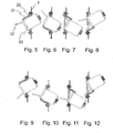
- FIGS. 5 to 12 each show different installation variants of a cover with an insert.
- 5 shows a third cover 29 with a second insert 30 on a support ring 1.
- the third cover 29 is provided with a labeling field 31.
- the second insert 30 contains a closure flap shown here in the open position 32. To close the flap 32 would have to be folded counterclockwise by about 100 ° against the second insert 30.
- a user accessible side and right of the support ring 1 is not shown here electrical or telecommunications installation, for example, on a channel of a domestic installation.
- the second insert 30 is rotatable in particular by 180 ° about a longitudinal direction to the paper plane.
- an adapter plate is not shown in Fig. 5 and in the following figures to Fig. 12. This can also be used between the support ring 1 and the third cover 29.
- the second insert 30 can also be designed so that it has a square cross-section, so that it can be inserted not only rotated by 180 ° about its longitudinal axis in the oblique outlet of the cover, but also in each case by 90 ° turned into this can be inserted. This increases the number of possible combinations again.
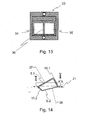
- FIG. 13 shows a fourth cover 33.
- This fourth cover 33 substantially corresponds to the first cover shown in FIG. 2 above.
- the oblique outlet here comprises a first 34 and a second segment 35, which are separated from each other by a central web 36.
- the 34 and the second segment 35 in this case have identical dimensions, so that two similar inserts, which are not shown here, can be accommodated.
- Figure 14 shows a fifth cover.
- This fifth cover substantially corresponds in the base area to the cover shown in FIG. 4.
- the fifth cover has an upper bulge 15.1 and a lower bulge 15.2.
- These have an upper outlet 5.1 and a lower outlet 5.2. Due to different heights of the bulges 15.1 and 15.2 from the base plane 21 can be realized depending on the installation position different heights or installation depths.
- the upper outlet 5.1 and the lower outlet 5.2 have different outlet directions from the upper outlet direction 37 and the lower outlet direction 38 on. Contrary to the desk-shaped bulges shown here, such a cover can also be realized with spherical cap-shaped, spherical bulges or generally irregular bulges and a combination derselbigen.
Landscapes
- Engineering & Computer Science (AREA)
- Architecture (AREA)
- Civil Engineering (AREA)
- Structural Engineering (AREA)
- Connector Housings Or Holding Contact Members (AREA)
- Casings For Electric Apparatus (AREA)
- Connections Arranged To Contact A Plurality Of Conductors (AREA)
- Fire-Detection Mechanisms (AREA)
Applications Claiming Priority (1)
| Application Number | Priority Date | Filing Date | Title |
|---|---|---|---|
| DE102005012332A DE102005012332A1 (de) | 2005-03-17 | 2005-03-17 | Abdeckung einer Anschlußvorrichtung |
Publications (2)
| Publication Number | Publication Date |
|---|---|
| EP1703608A1 true EP1703608A1 (fr) | 2006-09-20 |
| EP1703608B1 EP1703608B1 (fr) | 2007-11-14 |
Family
ID=36570645
Family Applications (1)
| Application Number | Title | Priority Date | Filing Date |
|---|---|---|---|
| EP06005031A Expired - Lifetime EP1703608B1 (fr) | 2005-03-17 | 2006-03-13 | Enjoliveur pour un dispositif de raccordement |
Country Status (4)
| Country | Link |
|---|---|
| EP (1) | EP1703608B1 (fr) |
| AT (1) | ATE378719T1 (fr) |
| DE (2) | DE102005012332A1 (fr) |
| ES (1) | ES2296237T3 (fr) |
Citations (4)
| Publication number | Priority date | Publication date | Assignee | Title |
|---|---|---|---|---|
| DE3842205A1 (de) * | 1988-12-15 | 1990-06-21 | Giersiepen Gira Gmbh | Gehaeuse fuer den anschluss von kommunikationssystemen |
| DE3930781A1 (de) * | 1989-09-14 | 1991-03-28 | Berker Geb | Abdeckanordnung fuer telekommunikations-steckdosen zum erhalt senkrechter oder schraeger leitungsfuehrungen |
| DE19608876A1 (de) * | 1996-03-07 | 1997-09-18 | Quante Ag | Geschirmte Anschlußdose |
| US6616005B1 (en) * | 2000-08-28 | 2003-09-09 | Hubbell Incorporated | Modular faceplate assembly for an electrical box |
-
2005
- 2005-03-17 DE DE102005012332A patent/DE102005012332A1/de not_active Withdrawn
-
2006
- 2006-03-13 DE DE502006000176T patent/DE502006000176D1/de not_active Expired - Lifetime
- 2006-03-13 ES ES06005031T patent/ES2296237T3/es not_active Expired - Lifetime
- 2006-03-13 AT AT06005031T patent/ATE378719T1/de not_active IP Right Cessation
- 2006-03-13 EP EP06005031A patent/EP1703608B1/fr not_active Expired - Lifetime
Patent Citations (4)
| Publication number | Priority date | Publication date | Assignee | Title |
|---|---|---|---|---|
| DE3842205A1 (de) * | 1988-12-15 | 1990-06-21 | Giersiepen Gira Gmbh | Gehaeuse fuer den anschluss von kommunikationssystemen |
| DE3930781A1 (de) * | 1989-09-14 | 1991-03-28 | Berker Geb | Abdeckanordnung fuer telekommunikations-steckdosen zum erhalt senkrechter oder schraeger leitungsfuehrungen |
| DE19608876A1 (de) * | 1996-03-07 | 1997-09-18 | Quante Ag | Geschirmte Anschlußdose |
| US6616005B1 (en) * | 2000-08-28 | 2003-09-09 | Hubbell Incorporated | Modular faceplate assembly for an electrical box |
Also Published As
| Publication number | Publication date |
|---|---|
| ATE378719T1 (de) | 2007-11-15 |
| ES2296237T3 (es) | 2008-04-16 |
| DE102005012332A1 (de) | 2006-09-21 |
| DE502006000176D1 (de) | 2007-12-27 |
| EP1703608B1 (fr) | 2007-11-14 |
Similar Documents
| Publication | Publication Date | Title |
|---|---|---|
| EP1999830B1 (fr) | Module de montage destine a installer un appareil dans une installation de commutation electrique | |
| EP1595318B1 (fr) | Passage de cables | |
| EP1311042B1 (fr) | Boîtier d' instalation électrique | |
| DE4222656C2 (de) | Elektrische Steckdose | |
| DE102005000020B4 (de) | Anordnung zur Halterung eines Installationsgeräte-Einsatzes an einer Tragplatte | |
| EP1703608B1 (fr) | Enjoliveur pour un dispositif de raccordement | |
| EP3100327B1 (fr) | Ensemble d'un élément d'accessoire sur un élément avec bride | |
| DE102021127587B3 (de) | Steckdosenleiste | |
| DE8817098U1 (de) | Gehäuse für den Anschluß von Kommunikationssystemen | |
| CH713572A2 (de) | Installationsdose für elektrische Anschlüsse. | |
| EP3382833B1 (fr) | Module de montage pour un système de montage modulaire comme un système de communication de porte et installation électronique de bâtiment et outil de montage pour un tel module de montage | |
| DE29922165U1 (de) | Anschlußdosenanordnung für Lichtwellenleiterkabel | |
| WO2014114491A2 (fr) | Prise électrique, destinée en particulier à une armoire de commande | |
| DE102021004837B4 (de) | Aufnahme- und Festlegevorrichtung, System, Schaltschrank und Anschlusssystem | |
| DE3721493C1 (en) | Designation-plate carrier for a plug-in-connector casing | |
| EP4109438B1 (fr) | Dispositif de scellage ses vis | |
| DE19845335A1 (de) | Geräteaufnahme für eine Unterflurgerätedose | |
| DE102010055663A1 (de) | Wandeinsatz | |
| DE29706450U1 (de) | Busverteiler | |
| DE102006037516B4 (de) | Abdecksystem für Elektroinstallationsdosen | |
| DE10019328C2 (de) | Verschluss | |
| DE19816110C2 (de) | Schilderpfosten mit Meßstelleneinrichtung | |
| DE19959882A1 (de) | Befestigungsvorrichtung | |
| DE10343056A1 (de) | Kabeldurchführung | |
| DE3919632C2 (fr) |
Legal Events
| Date | Code | Title | Description |
|---|---|---|---|
| PUAI | Public reference made under article 153(3) epc to a published international application that has entered the european phase |
Free format text: ORIGINAL CODE: 0009012 |
|
| AK | Designated contracting states |
Kind code of ref document: A1 Designated state(s): AT BE BG CH CY CZ DE DK EE ES FI FR GB GR HU IE IS IT LI LT LU LV MC NL PL PT RO SE SI SK TR |
|
| AX | Request for extension of the european patent |
Extension state: AL BA HR MK YU |
|
| 17P | Request for examination filed |
Effective date: 20061108 |
|
| AKX | Designation fees paid |
Designated state(s): AT BE BG CH CY CZ DE DK EE ES FI FR GB GR HU IE IS IT LI LT LU LV MC NL PL PT RO SE SI SK TR |
|
| GRAP | Despatch of communication of intention to grant a patent |
Free format text: ORIGINAL CODE: EPIDOSNIGR1 |
|
| GRAS | Grant fee paid |
Free format text: ORIGINAL CODE: EPIDOSNIGR3 |
|
| GRAA | (expected) grant |
Free format text: ORIGINAL CODE: 0009210 |
|
| RAP1 | Party data changed (applicant data changed or rights of an application transferred) |
Owner name: LEONI KABEL HOLDING GMBH & CO. KG |
|
| AK | Designated contracting states |
Kind code of ref document: B1 Designated state(s): AT BE BG CH CY CZ DE DK EE ES FI FR GB GR HU IE IS IT LI LT LU LV MC NL PL PT RO SE SI SK TR |
|
| REG | Reference to a national code |
Ref country code: GB Ref legal event code: FG4D Free format text: NOT ENGLISH |
|
| REG | Reference to a national code |
Ref country code: CH Ref legal event code: EP |
|
| REG | Reference to a national code |
Ref country code: IE Ref legal event code: FG4D Free format text: LANGUAGE OF EP DOCUMENT: GERMAN |
|
| REF | Corresponds to: |
Ref document number: 502006000176 Country of ref document: DE Date of ref document: 20071227 Kind code of ref document: P |
|
| GBT | Gb: translation of ep patent filed (gb section 77(6)(a)/1977) |
Effective date: 20080131 |
|
| REG | Reference to a national code |
Ref country code: CH Ref legal event code: NV Representative=s name: ZIMMERLI, WAGNER & PARTNER AG |
|
| REG | Reference to a national code |
Ref country code: ES Ref legal event code: FG2A Ref document number: 2296237 Country of ref document: ES Kind code of ref document: T3 |
|
| PG25 | Lapsed in a contracting state [announced via postgrant information from national office to epo] |
Ref country code: NL Free format text: LAPSE BECAUSE OF FAILURE TO SUBMIT A TRANSLATION OF THE DESCRIPTION OR TO PAY THE FEE WITHIN THE PRESCRIBED TIME-LIMIT Effective date: 20071114 Ref country code: SE Free format text: LAPSE BECAUSE OF FAILURE TO SUBMIT A TRANSLATION OF THE DESCRIPTION OR TO PAY THE FEE WITHIN THE PRESCRIBED TIME-LIMIT Effective date: 20080214 |
|
| NLV1 | Nl: lapsed or annulled due to failure to fulfill the requirements of art. 29p and 29m of the patents act | ||
| ET | Fr: translation filed | ||
| PG25 | Lapsed in a contracting state [announced via postgrant information from national office to epo] |
Ref country code: SI Free format text: LAPSE BECAUSE OF FAILURE TO SUBMIT A TRANSLATION OF THE DESCRIPTION OR TO PAY THE FEE WITHIN THE PRESCRIBED TIME-LIMIT Effective date: 20071114 Ref country code: LT Free format text: LAPSE BECAUSE OF FAILURE TO SUBMIT A TRANSLATION OF THE DESCRIPTION OR TO PAY THE FEE WITHIN THE PRESCRIBED TIME-LIMIT Effective date: 20071114 Ref country code: FI Free format text: LAPSE BECAUSE OF FAILURE TO SUBMIT A TRANSLATION OF THE DESCRIPTION OR TO PAY THE FEE WITHIN THE PRESCRIBED TIME-LIMIT Effective date: 20071114 Ref country code: PL Free format text: LAPSE BECAUSE OF FAILURE TO SUBMIT A TRANSLATION OF THE DESCRIPTION OR TO PAY THE FEE WITHIN THE PRESCRIBED TIME-LIMIT Effective date: 20071114 Ref country code: BG Free format text: LAPSE BECAUSE OF FAILURE TO SUBMIT A TRANSLATION OF THE DESCRIPTION OR TO PAY THE FEE WITHIN THE PRESCRIBED TIME-LIMIT Effective date: 20080214 Ref country code: LV Free format text: LAPSE BECAUSE OF FAILURE TO SUBMIT A TRANSLATION OF THE DESCRIPTION OR TO PAY THE FEE WITHIN THE PRESCRIBED TIME-LIMIT Effective date: 20071114 Ref country code: IS Free format text: LAPSE BECAUSE OF FAILURE TO SUBMIT A TRANSLATION OF THE DESCRIPTION OR TO PAY THE FEE WITHIN THE PRESCRIBED TIME-LIMIT Effective date: 20080314 |
|
| PG25 | Lapsed in a contracting state [announced via postgrant information from national office to epo] |
Ref country code: DK Free format text: LAPSE BECAUSE OF FAILURE TO SUBMIT A TRANSLATION OF THE DESCRIPTION OR TO PAY THE FEE WITHIN THE PRESCRIBED TIME-LIMIT Effective date: 20071114 Ref country code: CZ Free format text: LAPSE BECAUSE OF FAILURE TO SUBMIT A TRANSLATION OF THE DESCRIPTION OR TO PAY THE FEE WITHIN THE PRESCRIBED TIME-LIMIT Effective date: 20071114 |
|
| PG25 | Lapsed in a contracting state [announced via postgrant information from national office to epo] |
Ref country code: RO Free format text: LAPSE BECAUSE OF FAILURE TO SUBMIT A TRANSLATION OF THE DESCRIPTION OR TO PAY THE FEE WITHIN THE PRESCRIBED TIME-LIMIT Effective date: 20071114 Ref country code: SK Free format text: LAPSE BECAUSE OF FAILURE TO SUBMIT A TRANSLATION OF THE DESCRIPTION OR TO PAY THE FEE WITHIN THE PRESCRIBED TIME-LIMIT Effective date: 20071114 |
|
| PLBE | No opposition filed within time limit |
Free format text: ORIGINAL CODE: 0009261 |
|
| STAA | Information on the status of an ep patent application or granted ep patent |
Free format text: STATUS: NO OPPOSITION FILED WITHIN TIME LIMIT |
|
| BERE | Be: lapsed |
Owner name: LEONI KABEL HOLDING G.M.B.H. & CO. KG Effective date: 20080331 |
|
| PG25 | Lapsed in a contracting state [announced via postgrant information from national office to epo] |
Ref country code: PT Free format text: LAPSE BECAUSE OF FAILURE TO SUBMIT A TRANSLATION OF THE DESCRIPTION OR TO PAY THE FEE WITHIN THE PRESCRIBED TIME-LIMIT Effective date: 20080414 |
|
| REG | Reference to a national code |
Ref country code: IE Ref legal event code: FD4D |
|
| 26N | No opposition filed |
Effective date: 20080815 |
|
| PG25 | Lapsed in a contracting state [announced via postgrant information from national office to epo] |
Ref country code: MC Free format text: LAPSE BECAUSE OF NON-PAYMENT OF DUE FEES Effective date: 20080331 Ref country code: IE Free format text: LAPSE BECAUSE OF FAILURE TO SUBMIT A TRANSLATION OF THE DESCRIPTION OR TO PAY THE FEE WITHIN THE PRESCRIBED TIME-LIMIT Effective date: 20071114 |
|
| PG25 | Lapsed in a contracting state [announced via postgrant information from national office to epo] |
Ref country code: EE Free format text: LAPSE BECAUSE OF FAILURE TO SUBMIT A TRANSLATION OF THE DESCRIPTION OR TO PAY THE FEE WITHIN THE PRESCRIBED TIME-LIMIT Effective date: 20071114 Ref country code: GR Free format text: LAPSE BECAUSE OF FAILURE TO SUBMIT A TRANSLATION OF THE DESCRIPTION OR TO PAY THE FEE WITHIN THE PRESCRIBED TIME-LIMIT Effective date: 20080215 |
|
| PG25 | Lapsed in a contracting state [announced via postgrant information from national office to epo] |
Ref country code: BE Free format text: LAPSE BECAUSE OF NON-PAYMENT OF DUE FEES Effective date: 20080331 |
|
| PG25 | Lapsed in a contracting state [announced via postgrant information from national office to epo] |
Ref country code: CY Free format text: LAPSE BECAUSE OF FAILURE TO SUBMIT A TRANSLATION OF THE DESCRIPTION OR TO PAY THE FEE WITHIN THE PRESCRIBED TIME-LIMIT Effective date: 20071114 |
|
| PG25 | Lapsed in a contracting state [announced via postgrant information from national office to epo] |
Ref country code: AT Free format text: LAPSE BECAUSE OF NON-PAYMENT OF DUE FEES Effective date: 20080313 |
|
| REG | Reference to a national code |
Ref country code: CH Ref legal event code: PFA Owner name: LEONI KABEL HOLDING GMBH & CO. KG Free format text: LEONI KABEL HOLDING GMBH & CO. KG#STIEBERSTRASSE 5#91154 ROTH (DE) -TRANSFER TO- LEONI KABEL HOLDING GMBH & CO. KG#STIEBERSTRASSE 5#91154 ROTH (DE) |
|
| PG25 | Lapsed in a contracting state [announced via postgrant information from national office to epo] |
Ref country code: LU Free format text: LAPSE BECAUSE OF NON-PAYMENT OF DUE FEES Effective date: 20080313 Ref country code: HU Free format text: LAPSE BECAUSE OF FAILURE TO SUBMIT A TRANSLATION OF THE DESCRIPTION OR TO PAY THE FEE WITHIN THE PRESCRIBED TIME-LIMIT Effective date: 20080515 |
|
| PG25 | Lapsed in a contracting state [announced via postgrant information from national office to epo] |
Ref country code: TR Free format text: LAPSE BECAUSE OF FAILURE TO SUBMIT A TRANSLATION OF THE DESCRIPTION OR TO PAY THE FEE WITHIN THE PRESCRIBED TIME-LIMIT Effective date: 20071114 |
|
| REG | Reference to a national code |
Ref country code: CH Ref legal event code: PL |
|
| GBPC | Gb: european patent ceased through non-payment of renewal fee |
Effective date: 20100313 |
|
| PG25 | Lapsed in a contracting state [announced via postgrant information from national office to epo] |
Ref country code: CH Free format text: LAPSE BECAUSE OF NON-PAYMENT OF DUE FEES Effective date: 20100331 Ref country code: LI Free format text: LAPSE BECAUSE OF NON-PAYMENT OF DUE FEES Effective date: 20100331 Ref country code: IT Free format text: LAPSE BECAUSE OF FAILURE TO SUBMIT A TRANSLATION OF THE DESCRIPTION OR TO PAY THE FEE WITHIN THE PRESCRIBED TIME-LIMIT Effective date: 20071114 |
|
| PG25 | Lapsed in a contracting state [announced via postgrant information from national office to epo] |
Ref country code: GB Free format text: LAPSE BECAUSE OF NON-PAYMENT OF DUE FEES Effective date: 20100313 |
|
| PGFP | Annual fee paid to national office [announced via postgrant information from national office to epo] |
Ref country code: ES Payment date: 20130320 Year of fee payment: 8 |
|
| REG | Reference to a national code |
Ref country code: DE Ref legal event code: R082 Ref document number: 502006000176 Country of ref document: DE Representative=s name: PATENTANWAELTE LIPPERT, STACHOW & PARTNER, DE Ref country code: DE Ref legal event code: R082 Ref document number: 502006000176 Country of ref document: DE Representative=s name: FDST PATENTANWAELTE FREIER DOERR STAMMLER TSCH, DE |
|
| REG | Reference to a national code |
Ref country code: ES Ref legal event code: FD2A Effective date: 20150731 |
|
| PG25 | Lapsed in a contracting state [announced via postgrant information from national office to epo] |
Ref country code: ES Free format text: LAPSE BECAUSE OF NON-PAYMENT OF DUE FEES Effective date: 20140314 |
|
| REG | Reference to a national code |
Ref country code: DE Ref legal event code: R082 Ref document number: 502006000176 Country of ref document: DE Representative=s name: FDST PATENTANWAELTE FREIER DOERR STAMMLER TSCH, DE |
|
| REG | Reference to a national code |
Ref country code: FR Ref legal event code: PLFP Year of fee payment: 11 |
|
| REG | Reference to a national code |
Ref country code: FR Ref legal event code: PLFP Year of fee payment: 12 |
|
| REG | Reference to a national code |
Ref country code: FR Ref legal event code: PLFP Year of fee payment: 13 |
|
| REG | Reference to a national code |
Ref country code: DE Ref legal event code: R081 Ref document number: 502006000176 Country of ref document: DE Owner name: KERPEN DATACOM GMBH, DE Free format text: FORMER OWNER: LEONI KABEL HOLDING GMBH & CO. KG, 91154 ROTH, DE Ref country code: DE Ref legal event code: R082 Ref document number: 502006000176 Country of ref document: DE Representative=s name: FDST PATENTANWAELTE FREIER DOERR STAMMLER TSCH, DE Ref country code: DE Ref legal event code: R081 Ref document number: 502006000176 Country of ref document: DE Owner name: LEONI KABEL GMBH, DE Free format text: FORMER OWNER: LEONI KABEL HOLDING GMBH & CO. KG, 91154 ROTH, DE |
|
| REG | Reference to a national code |
Ref country code: DE Ref legal event code: R081 Ref document number: 502006000176 Country of ref document: DE Owner name: KERPEN DATACOM GMBH, DE Free format text: FORMER OWNER: LEONI KABEL GMBH, 91154 ROTH, DE |
|
| PGFP | Annual fee paid to national office [announced via postgrant information from national office to epo] |
Ref country code: DE Payment date: 20250326 Year of fee payment: 20 |
|
| PGFP | Annual fee paid to national office [announced via postgrant information from national office to epo] |
Ref country code: FR Payment date: 20250324 Year of fee payment: 20 |
|
| REG | Reference to a national code |
Ref country code: DE Ref legal event code: R071 Ref document number: 502006000176 Country of ref document: DE |