EP1701468A1 - Variable communication capacity data transmission device - Google Patents
Variable communication capacity data transmission device Download PDFInfo
- Publication number
- EP1701468A1 EP1701468A1 EP20050026648 EP05026648A EP1701468A1 EP 1701468 A1 EP1701468 A1 EP 1701468A1 EP 20050026648 EP20050026648 EP 20050026648 EP 05026648 A EP05026648 A EP 05026648A EP 1701468 A1 EP1701468 A1 EP 1701468A1
- Authority
- EP
- European Patent Office
- Prior art keywords
- data
- transmission
- unit
- reception
- capacity
- Prior art date
- Legal status (The legal status is an assumption and is not a legal conclusion. Google has not performed a legal analysis and makes no representation as to the accuracy of the status listed.)
- Withdrawn
Links
- 230000005540 biological transmission Effects 0.000 title claims abstract description 296
- 238000004891 communication Methods 0.000 title claims abstract description 125
- 238000006243 chemical reaction Methods 0.000 claims description 92
- 238000012545 processing Methods 0.000 claims description 36
- 238000007689 inspection Methods 0.000 claims description 15
- 230000003287 optical effect Effects 0.000 claims description 10
- 230000006870 function Effects 0.000 claims description 9
- 238000012544 monitoring process Methods 0.000 claims 8
- 238000003491 array Methods 0.000 claims 3
- 238000000034 method Methods 0.000 description 17
- 230000002776 aggregation Effects 0.000 description 11
- 238000004220 aggregation Methods 0.000 description 11
- 239000013307 optical fiber Substances 0.000 description 8
- 101710142585 50S ribosomal protein 6, chloroplastic Proteins 0.000 description 5
- 238000003860 storage Methods 0.000 description 5
- 101001080597 Spinacia oleracea 50S ribosomal protein 5 alpha, chloroplastic Proteins 0.000 description 4
- 238000012790 confirmation Methods 0.000 description 4
- 230000008859 change Effects 0.000 description 3
- 238000012937 correction Methods 0.000 description 3
- 238000012986 modification Methods 0.000 description 3
- 230000004048 modification Effects 0.000 description 3
- 101710083129 50S ribosomal protein L10, chloroplastic Proteins 0.000 description 2
- 238000010276 construction Methods 0.000 description 2
- 238000001514 detection method Methods 0.000 description 2
- 239000000284 extract Substances 0.000 description 2
- 238000012935 Averaging Methods 0.000 description 1
- 101100172132 Mus musculus Eif3a gene Proteins 0.000 description 1
- RGNPBRKPHBKNKX-UHFFFAOYSA-N hexaflumuron Chemical compound C1=C(Cl)C(OC(F)(F)C(F)F)=C(Cl)C=C1NC(=O)NC(=O)C1=C(F)C=CC=C1F RGNPBRKPHBKNKX-UHFFFAOYSA-N 0.000 description 1
- 230000014759 maintenance of location Effects 0.000 description 1
- 230000008569 process Effects 0.000 description 1
- 230000009467 reduction Effects 0.000 description 1
- 238000012546 transfer Methods 0.000 description 1
Images


Classifications
-
- H—ELECTRICITY
- H04—ELECTRIC COMMUNICATION TECHNIQUE
- H04L—TRANSMISSION OF DIGITAL INFORMATION, e.g. TELEGRAPHIC COMMUNICATION
- H04L25/00—Baseband systems
- H04L25/02—Details ; arrangements for supplying electrical power along data transmission lines
- H04L25/14—Channel dividing arrangements, i.e. in which a single bit stream is divided between several baseband channels and reassembled at the receiver
-
- H—ELECTRICITY
- H04—ELECTRIC COMMUNICATION TECHNIQUE
- H04J—MULTIPLEX COMMUNICATION
- H04J14/00—Optical multiplex systems
- H04J14/02—Wavelength-division multiplex systems
- H04J14/0227—Operation, administration, maintenance or provisioning [OAMP] of WDM networks, e.g. media access, routing or wavelength allocation
- H04J14/0241—Wavelength allocation for communications one-to-one, e.g. unicasting wavelengths
- H04J14/0242—Wavelength allocation for communications one-to-one, e.g. unicasting wavelengths in WDM-PON
- H04J14/0245—Wavelength allocation for communications one-to-one, e.g. unicasting wavelengths in WDM-PON for downstream transmission, e.g. optical line terminal [OLT] to ONU
- H04J14/0246—Wavelength allocation for communications one-to-one, e.g. unicasting wavelengths in WDM-PON for downstream transmission, e.g. optical line terminal [OLT] to ONU using one wavelength per ONU
-
- H—ELECTRICITY
- H04—ELECTRIC COMMUNICATION TECHNIQUE
- H04J—MULTIPLEX COMMUNICATION
- H04J14/00—Optical multiplex systems
- H04J14/02—Wavelength-division multiplex systems
- H04J14/0227—Operation, administration, maintenance or provisioning [OAMP] of WDM networks, e.g. media access, routing or wavelength allocation
-
- H—ELECTRICITY
- H04—ELECTRIC COMMUNICATION TECHNIQUE
- H04J—MULTIPLEX COMMUNICATION
- H04J14/00—Optical multiplex systems
- H04J14/02—Wavelength-division multiplex systems
- H04J14/0278—WDM optical network architectures
- H04J14/0279—WDM point-to-point architectures
Definitions
- the present invention relates to a variable communication capacity data transmission device. More particularly, it relates to a variable communication capacity data transmission device that forms one virtual transmission path by plural transmission lines, and changes transmission rates by automatically negotiating the number of transmission lines between a transmission side and a reception side according to a requested band and a connection state of the transmission lines.
- a link aggregation method is known as a communication method of line aggregation type that forms one logical high-speed transmission path by plural transmission lines ( IEEE Std 802.3-2002 Edition, “Part 3: Carrier sense multiple access with collision detection (CSMA/CD) access method and physical layer specifications”, Clause 43 "Link Aggregation", IEEE, 2002.3.8 ).
- the link aggregation method allocates data frames to each transmission line on a flow basis.
- the flow indicates a series of data frames identified by combinations of source addresses of transmission frames, destination addresses, and applications used. No special relationship is required between flows during data transmission (frame transmission). However, a reception side must guarantee the order of data frames within each flow, and the order of frames must not be reversed in a network.
- a device of transmission side assigns sequence numbers to transmission frames and allocates the transmission frames to a transmission buffer containing a small amount of data to be transmitted, and transmits the transmission frames to a line associated with the transmission buffer, while a device of a reception side temporarily stores the received frames in a reception buffer, and then reads the transmission frames in the order of sequence numbers.
- a communication system of line aggregation type is proposed that prevents the reversal of frame order by the above-mentioned arrangement (see JP-A No. 9866/2002 ).
- the number of communication interfaces increases in proportion to desired communication capacities. Therefore, users who consider approximately a triple increase in costs to be proper when communication capacity increases 10 times will find this method expensive.
- the link aggregation which handles data frames on a flow basis, requires processor operation for flow detection and allocation of transmission frames to specific lines, impeding speedup. Moreover, since data frames belonging to identical flows are transmitted through identical lines to guarantee the order of transmission frames (transmission packets), there is a problem that the occurrence of unused lines reduces transmission efficiency when the number of flows is smaller than the number of lines.
- JP-A No. 9866/2002 temporarily stores received data frames in a reception device and reads them in the order of sequence numbers. Therefore, even if the data frames are stored in a reception buffer, when a data frame having a next read sequence number specified by an internal counter does not arrive, a read operation must be halted until the data frame arrives. Time for waiting for a target data frame is managed by a timer reset each time a data frame is read from the reception buffer. Accordingly, when a target data frame is lost in the middle of a transmission path, the method described in JP-A No. 9866/2002 completely halts a read operation on received data frames until the timer turns time-out, inevitably causing reduction in transmission efficiency.
- variable communication capacity that can set bands according to users' requests, automatically determine usable lines, and set line communication capacities.
- a variable communication capacity data transmission device of the present invention has a function that the above-mentioned transmission capacity negotiation unit connected to a transmission side of N lines (N is a natural number satisfying N > 1) constituting one virtual transmission path determines the specified transmission capacity and the specified transmission line position, and the above-mentioned reception capacity negotiation unit connected to a reception side of N lines constituting one virtual reception path determines the specified reception capacity and the specified reception line position.
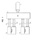
- FIG. 1 shows an example of a communication system of line aggregation type to which the present invention is applied.
- a communication system includes plural communication devices 10 (10A-10K) and wavelength division multiplexer (WDM) 5.
- the communication device 10A is connected to the WDM 5 through a transmission line LT-A and a reception line LR-A that each include plural serial lines (optical fibers).
- the communication device 10K is connected to the WDM 5 through a transmission line LT-K and a reception line LR-K that each including plural optical fibers.
- the WDM 5 which is connected to an optical fiber 2 serving as part of an optical communication network, wavelength-multiplexes optical signals received from the transmission lines LT-A to LT-K, and transmits them to the optical fiber 2. It also wavelength-demultiplexes wavelength-multiplexed optical signals received from the optical fiber 2 and outputs the resulting signals to the reception lines LR-A to LR-K.
- the transmission line LT-A and the reception line LR-A, and the transmission line LT-K and the reception line LR-K may, in connection with the WDM 5, be integrated into one optical fiber through which plural optical signals are wavelength-multiplexed and transmitted.
- the WDM may be connected with plural optical fibers of the optical communication network.
- Connection by plural optical fibers even if any path of a line used is disconnected and disabled, can prevent communication from being disabled by using only other usable paths though communication capacity is reduced.
- FIG. 2 shows a communication device according to an aspect of the present invention.
- a communication device 10TX (a transmitting side of the communication device 10 or the WDM 5 of FIG. 1) includes a transmission interface 20, a processor unit 30, and a storage unit 40.
- a communication device 10RX (a receiving side of the communication device 10 or the WDM 5 of FIG. 1), which is connected opposite to the communication device 10TX, includes a reception interface 25, a processor unit 30', and a storage unit 40'.
- the transmission interface 20 includes a protocol processing unit 50, a transmission unit 60, and a negotiation unit 70.
- the reception interface 25 includes a protocol processing unit 50', a reception unit 80, and a negotiation unit 70'.
- the transmission interface 20 is connected with the processor unit 30 through a bus L10.
- the transmission unit 60 of the transmission interface 20 is connected with the reception unit 80 of the reception interface 25 through plural serial lines LT1 to LT4.
- the processor unit 30 executes various application programs stored in the storage unit 40, and outputs transmission data for other communication devices (or computers) connected through the communication network to the transmission interface 20.
- the protocol processing unit 50 has part or all of protocol processing functions from the application layer to the data link layer which are shown in the OSI (Open System Interconnection) basic model. However, the processor unit 30 may perform part of processing from the application layer to the data link layer.
- the protocol processing unit 50 receives transmission data from the processor unit, converts transmission data into a transmission data frame, and outputs the transmission data frame to the transmission data bus L20 according to a transmission control signal CL10 outputted by the transmission unit 60.
- the transmission unit 60 transmits the transmission data frame outputted by the protocol processing unit 50 to the communication device 10RX through the serial lines LT1 to LT4.
- the reception unit 80 receives the data frame transmitted by the communication device 10TX and outputs the received data frame by using the reception data bus L30 and a reception control signal CL50.
- the protocol processing unit 50' has part or all of processing functions from the data link layer to the application layer, converts the received data frame into reception data, and outputs the reception data to the processor unit 30' through the data bus L10.
- the processor unit 30' executes various application programs stored in the storage unit 40', and processes the reception data inputted from the reception interface 25.
- the following details a method of negotiating the number and position of lines used of the serial lines LT1 to LT4 between the communication devices 10TX and RX.
- the negotiation unit 70 of the communication device 10TX outputs a control signal for outputting a pattern for inspecting a line state through the output control signal line CL30.
- the transmission unit 60 transmits the inspection pattern to the serial lines LT1 to LT4 according to a control signal inputted from the output control signal line CL30.
- the reception unit 80 of the communication device 10RX detects a line state from the inspection pattern received from the serial lines LT1 to LT4, and outputs line state information to the negotiation unit 70' through the signal lines CL60 and CL65.
- the negotiation unit 70' determines a usable line from the line state information obtained from signal line CL60 and CL65, and outputs usable line information to the communication device 10TX through notification means CL80.
- the negotiation unit 70 of the communication device 10TX determines a specified transmission capacity and a specified transmission line position from the usable line information received from the notification means CL80 and a communication capacity request sent through the signal line CL40 by the processor unit 30. Furthermore, it outputs to the transmission unit 60 the specified transmission capacity through the signal line CL20 and the specified transmission line position through the signal line CL25, and at the same time notifies the processor unit 30 of the set specified transmission capacity.
- the transmission unit 60 transmits the line use information to the communication device 10RX through the serial lines LT1 to LT4 according to the specified transmission capacity and the specified transmission line position.
- the reception unit 80 detects a line state of the serial lines LT1 to LT4, and outputs line state information to the negotiation unit 70' through the signal lines CL60 and CL65.
- the negotiation unit 70' determines the specified reception capacity and the specified reception line position based on the line state information obtained from the signal lines CL60 and CL65, outputs to the reception unit 80 the specified reception capacity through the signal line CL70 and the specified reception line position through the signal line CL75, and notifies the processor unit 30' of the set specified reception capacity through the signal line CL40'.
- the setting of the transmission interface and the reception interface can be automatically set according to a line connection state between the transmission interface and the reception interface, and a communication capacity request from the processors (or, administrator).
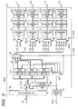
- FIG. 3 shows the transmission unit according to an aspect of the present invention.
- the buffer memory 100, the buffer control unit 130, the selector 120, and the rate conversion unit 110 form a transmission data array conversion unit, and components from the rate selector 140 to the electric/optic (E/O) conversion units 180-i form a transmission data output unit.
- the protocol processing unit 50 outputs a transmission data frame having a width of 4n bits to the transmission data bus L20.
- the protocol processing unit 50 may output a transmission data frame having a width of m bits (m is a natural number) to the transmission data bus L20 and convert it into data having a width of 4n bits by a converter provided in a pre-stage (or a subsequent stage) of the buffer memory 100.
- the protocol processing unit 50 may write a transmission data frame having a width of m bits outputted to a transmission data bus L20 to the buffer memory 100 and convert it into data having a width of 4n bits when reading it from the buffer memory 100.
- bit width of bits outputted by the protocol processing unit and a bit width of the transmission unit are the same, needless bit width conversion can be avoided. In many cases, they are different. If m is simply an integer multiple of 4n, bit conversion can be easily performed by the latter method. However, if not, like the former, it is necessary to provide a complicated circuit that performs bit conversion and clock conversion.
- a data frame having a width of 4n bits outputted to the transmission data bus L20 by the protocol processing unit 50 is temporarily stored in the buffer memory 100 by the buffer control unit 130, and then is read into the output line L21.
- the buffer control unit 130 issues a command for commanding the protocol processing unit 50 to halt the output of the data frame through the control signal line CL10, and when a sufficient empty area comes into existence, commands the protocol processing unit 50 to transmit the data frame.
- the pattern generation unit 155 prepares continuous inspection patterns as parallel data having a width of 4n bits so that the reception unit 80 constituting the reception interface 25 can inspect the continuity of received data.
- the data selector 160 is supplied with parallel data having a width of 4n bits outputted to the output line L21 of the buffer memory 100 and the output line of the pattern generation unit 155. Either of the parallel data is selected according to the data select signal CL30 and outputted to the output line L22.
- the rate conversion units 110 are supplied with parallel data having a width of 4n bits outputted to the output line L22 from the data selector 160.
- the first rate conversion unit 110-1 operates as a 3/4 rate converter that converts parallel input data having a width of 4n bits into parallel data having a width of 3n bits and outputs it.
- the second rate conversion unit 110-2 operates as a 1/2 rate converter that converts parallel input data having a width of 4n bits into parallel data having a width of 2n bits and outputs it.
- the third rate conversion unit 110-3 operates as a 1/4 rate converter that converts parallel input data having a width of 4n bits into parallel data having a width of n bits and outputs it.
- the rate selector 140 is supplied with parallel data having a width of 4n bits outputted to the output line L22, and the conversion units 110 (110-1 to 110-3).
- the rate selector 140 selects which bit line L22 the data has been inputted, and with what bit width the data is to be outputted, according to specified of the specified transmission capacity signal CL20.
- the parallel data inputted to the rate selector 140 differs in bit width from n to 4n bits, but is outputted in 4n bits.
- the parallel data is inputted with a bit width fewer than 4n (e.g., n-bit width)
- data of a lacking bit width is filled with null data (e.g., the value 0).
- the parallel data having a width of 4n bits of the output line L23 is separated into four trains of data (output lines L1 to L4) each having a width of n bits.
- the buffer control unit 130 adjusts a data amount read from the buffer memory 100 according to a specified transmission capacity signal fed from the control signal line CL20.
- one of data output control signals outputted by the rate conversion units 110-1 to 110-3 is inputted to the buffer control unit 130 by controlling input selection by the selector 120 by the specified transmission capacity signal CL20.
- a signal indicating always read permission is inputted for first input indicative of full mode time (when the output bus L21 is selected by the rate selector 140) by the selector 120.
- the selector 120 outputs the data output control signal outputted by the first rate conversion unit 110-1 to the buffer control unit 130.
- the buffer control unit 130 controls the amount of output data to the output bus L21 by controlling the amount of data to be read from the buffer memory 100.
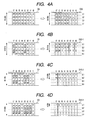
- FIGS. 4A to 4D show relationships among a state of the specified transmission capacity signal CL20 according to an aspect of the present invention, data appearing in the output bus L21, and data appearing in the output line L1-L4 of the rate selector 140.
- FIG. 4A shows a relationship between a data train D0 appearing in the output bus L21 and an output data train D20 appearing in the output lines L1-L4 when the specified transmission capacity signal CL20 indicates a maximum capacity (full mode).
- t0 to t7 indicate a power cycle of 4n-bit data
- digits "0" to "31” indicate a data number indicating an n-bit data block (alignment order).
- a data train D0 having a width of 4n bits is continuously outputted to the output bus L21 without empty cycles occurring.
- the output data train D0 is separated to four data trains each having a width of n bits, and the data trains each having a width of n bits appear in the output lines L1 to L4 as a data block array indicated by D20.
- FIG. 4B shows a relationship between a data train D0 appearing in the output bus L21 and an output data train D20 appearing in the output lines L1-L4 when the specified transmission capacity signal CL20 indicates 3/4 mode.
- a data train D1 having a width of 4n bits is outputted to the output bus L21 in a form that contains empty data cycles (t3, t7, ...) at the rate of one to four cycles.
- the output data train D1 is inputted to the rate conversion units 110-1 to 110-3, in the 3/4 mode, the output becomes effective in the first rate conversion unit 110-1.
- the first rate conversion unit 110-1 converts a data train (data blocks “0" to “11” and “12” to “23") having a width of 4n bits inputted in the period of three consecutive effective data cycles (t0-t2, t4-t6, ...) into a data train having a width of 3n bits, and outputs it in four cycles.
- the data train having a width of 3n bits outputted from the first rate conversion unit 110-1 is separated to three data trains each having a width of n bits, which are supplied as a second input of the rate selector 140.
- transmission data appears in the output lines L1-L3 as a data block array shown in D25-1.
- FIG. 4C shows a relationship between a data train D0 appearing in the output bus L21 and an output data train D25-2 appearing in the output lines L1 to L4 when the specified transmission capacity signal CL20 indicates 1/2 mode.
- a data train D2 having a width of 4n bits is outputted to the output bus L21 in a form that contains empty data cycles (t2, t3, t6, t7, ...) at the rate of two to four cycles.
- the output data train D2 is inputted to the rate conversion units 110-1 to 110-3, in the 1/2 mode, the output becomes effective in the second rate conversion unit 110-2.
- the second rate conversion unit 110-2 converts a data train (data blocks “0" to "7” and “8” to "15") having a width of 4n bits inputted in the period of two consecutive effective data cycles (t0-t1, t4-t5, ...) into a data train having a width of 2n bits, and outputs it in four cycles.
- the data train having a width of 2n bits outputted from the second rate conversion unit 110-2 is separated to two data trains each having a width of n bits, which are supplied as a third input of the rate selector 140.
- transmission data appears in the output lines L1 and L2 as a data block array shown in D25-2.
- FIG. 4D shows a relationship between a data train D0 appearing in the output bus L21 and an output data train D25-3 appearing in the output lines L1 to L4 when the specified transmission capacity signal CL20 indicates 1/4 mode.
- a data train D3 having a width of 4n bits is outputted to the output bus L21 in a form that contains empty data cycles (t1-t3, t5-t7, ...) at the rate of three to four cycles.
- the output data train D3 is inputted to the rate conversion units 110-1 to 110-3, in the 1/4 mode, the output becomes effective in the third rate conversion unit 110-3.
- the third rate conversion unit 110-3 converts a data train (data blocks “0" to “3” and “4" to “7") having a width of 4n bits inputted in the period of consecutive effective data cycles (t0, t4, 7) into a data train having a width of n bits, and outputs it in four cycles.
- the data train having a width of n bits outputted from the third rate conversion unit 110-3 is supplied as a fourth input of the rate selector 140.
- transmission data appears in the output line L1 as a data block array shown in D25-3.
- the pattern generation unit 155 generates data in the same data block array as that of parallel data having a width of 4n bits outputted by the buffer memory 100 and the buffer control unit 130. For example, when the selector 120 selects the 3/4 mode (outputs a data output control signal of the rate conversion unit 110-1), the pattern generation unit 155 generates a continuous inspection pattern in the same block array as that of the data train D0 of FIG. 4B.
- the line selectors 150 (150-1 to 150-4) allocates the output lines LT1 to LT4 to any of the lines based on the specified transmission line position signal CL25.
- the line selector 150-1 inputs the output line L1 and a null signal.
- the line selector 150-2 inputs the output lines L1 and L2, and a null signal.
- the line selector 150-3 inputs the output lines L1 to L3 and a null signal.
- the line selector 150-4 inputs the output lines L1 to L4 and a null signal.
- the specified transmission line position signal CL25 feeds selection signals shown in FIG. 8 to each of the line selectors 150. In FIG.
- L1 to L4 may be inputted to all line selectors 150 so that the order of L1 to L4 can be interchanged.
- the transmission codes have the function of averaging the probability of occurrences of "0" and "1" in the case of binary transmission, for example, to assure DC balance in transmission paths.
- the above-mentioned transmission codes can include communication control information besides user data.
- FIG. 5 shows a reception unit of the communication device 10RX according to an aspect of the present invention.
- Components from the O/E conversion units 200-i to the line selectors 230-1 to 230-3, 235-1, 235-2, and 240 form a reception data input unit.
- the rate conversion units 250-1 to 250-3 form a reception data array conversion unit.
- the rate selector 260, the selector 265, the reception buffer 275, and the buffer control unit 270 form a reception data output unit.
- the O/E conversion unit 200-i convert optical signals received from the reception lines LRi into electrical signals of serial data form.
- the S/P conversion and code synchronization units 205-i converts the serial data outputted from the O/E conversion units 200-i into parallel data having a width of n bits, and detects a code separator of transmission code (detects a comma in the case of 8B10B code).
- the code synchronization confirmation unit 210 confirms a code synchronization state of the S/P conversion and code synchronization units 205-1 to 205-4, and sends synchronization state information through the signal line CL60.
- the decoding unit 220-i execute conversion reverse to transmission encoding performed by the transmission unit 60 of the communication device 10TX.
- the skew control unit 225 detects, from the result of encoding by the decoding units 220-1 to 220-4, the difference (skew) between data arrival times that occurred between links of the network during data transmission, and controls the skew correction units 215-1 to 215-4 to cancel out the skew.
- the line selectors 230-1 to 230-3, 235-1, 235-2, and 240 select a signal line inputted from one of input lines TR1 to TR4 based on the specified reception line position signal CL75 according to the control signal line CL70.
- the control signal line CL70 is inputted from the negotiation part 20' so that the line selectors 230-1 to 230-3, 235-1, 235-2, and 240 select lines shown by FIG. 9.
- FIG. 9A shows combinations of selections by the line selectors 230-1 to 230-3 in the 3/4 mode.
- the line selectors 230-1 to 230-3 each selectively output parallel data having a width of n bits of one of the signal lines L1 to L4 according to line positions 1 to 4 indicated by the specified reception line position signal CL75.
- FIG. 9A shows combinations of selections by the line selectors 230-1 to 230-3 in the 3/4 mode.
- the line selectors 230-1 to 230-3 each selectively output parallel data having a width of n bits of one
- FIG. 9B shows combinations of selections by the line selectors 235-1 and 235-2 in the 1/2 mode.
- the line selectors 235-1 to 235-2 each selectively output parallel data having a width of n bits of one of the signal lines L1 to L4 according to line positions 1 to 4 indicated by the specified reception line position signal CL75.
- FIG. 9C shows a combination of selections by the line selector 240 in the 1/4 mode.
- the line selector 240 selectively outputs parallel data having a width of n bits of one of the signal lines L1 to L4 according to line positions 1 to 4 indicated by the specified reception line position signal CL75.
- the rate conversion parts 250-1 to 250-3 perform rate conversion reverse to the rate conversion performed by the transmission unit 60 of the communication device 10TX. That is, the rate conversion unit 250-1 converts a data train having a width of n bits outputted from the line selector 240 into a data train having a width of 4n bits that contains three null data cycles every four cycles4, and supplies it as a fourth input of the rate selector 260.
- the rate conversion unit 250-2 converts a data train having a width of 2n bit that includes a data train having a width of n bits outputted from the line selector 235-1 and a data train having a width of n bits outputted from the line selector 235-2 into a data train having a width of 4n bits containing two null data cycles every four cycles, and supplies it as a third input of the rate selector 260.
- the rate conversion unit 250-3 converts a data train having a width of 3n bits including three data trains each having a width of n bits outputted from the line selectors 230-1 to 230-3 into a data train having a width of 4n bits containing one null data cycle every four cycles, and supplies it as a second input of the rate selector 260.
- the rate selector 260 is supplied, as a first input, with a data train having a width of 4n bits including four data trains each having a width of n bits outputted from the decoding units 220-1 to 220-4.
- the rate selector 260 selects any one from among the above-mentioned first input to fourth input according to a specified reception capacity signal specified by the processor 30' through the control signal line CL70, and outputs it to the reception buffer 275.
- the buffer control unit 270 controls the writing and reading of data to and from the reception buffer 275.
- the buffer control unit 270 writes data to the reception buffer 275 in the first half of each cycle and reads data into the reception bus L30 from the reception buffer 275 in the second half.
- the rate conversion units 250-i output control signals indicating effective data cycles so that the buffer control unit 270 writes data to the reception buffer 275 in effective data cycles.
- the control signals are inputted to the selector 265, and one control signal selected by the selector 265 according to the specified reception capacity signal is supplied to the buffer control unit 270.
- the rate selector 260 selects a data train from the rate conversion unit 250-1 supplied as a fourth input, and the buffer control unit 270, according to a control signal from the rate conversion unit 250-1 selected by the selector 265, writes data having a width of 4n bits in effective data cycles outputted by the rate conversion unit 250-1 to the reception buffer 275.
- the 1/2 mode data having a width of 4n bits in effective data cycles outputted by the rate conversion unit 250-2 is written to the reception buffer 275.
- the 3/4 mode data having a width of 4n bits in effective data cycles outputted by rate conversion unit 250-3 is written to the reception buffer 275.
- null data is outputted to the reception bus L30.
- the rate selector 260 selects the first input and the selector 265 selects an enable signal fed as the first input. Accordingly, in this mode, the writing and reading of effective data to and from the reception buffer 275 are performed in all cycles.
- the communication device of the present invention can changeably control the number of lines connected with a communication network. Therefore, when communication data quantity is small, a small number of lines are used, and with an increase in communication data quantity, the number of lines is increased in stages. By doing so, it becomes possible to make a band use contract to meet demands with a communication service provider.
- the negotiation unit 70 of the communication device 10TX outputs a control signal for outputting a pattern for inspecting a line state through the output control signal line CL30.
- the data selector 160 of the transmission unit 60 selects an inspection pattern outputted by the pattern generation unit 155, the inspection pattern is outputted to the lines LT1 to LT4.
- the reception unit 80 of the communication device 10RX detects a line connection state from the inspection pattern received from the serial lines LR1 to LR4 of the reception side, and outputs line synchronization information of a usable line with code synchronization established to the negotiation part 70' through the signal line CL60.
- the negotiation unit 70' determines a usable line from the line state information obtained from the signal line CL60, and sends usable line information to the communication device 10TX through notification means CL80.
- the negotiation unit 70 of the communication device 10TX determines a specified transmission capacity and a specified transmission line position according to the usable line information received from the notification means CL80 and a communication capacity request sent by the processor unit 30 through the signal line CL40. Moreover, the negotiation unit 70 outputs the specified transmission capacity through the signal line CL20 and the specified transmission line position through the signal line CL25 to the transmission unit 60, and at the same time notifies the processor unit 30 of the specified transmission capacity.
- the transmission unit 60 determines the lines LT1 to LT4 to be used from the specified transmission capacity and the specified transmission line position, and outputs ineffective signals for the lines not to be used. Accordingly, in the reception unit 80 of the communication device 10RX, the code synchronization confirmation unit 210 detects again a synchronization state of the serial lines LT1 to LT4, and sends line synchronization information to the negotiation unit 70' through the signal line CL60. Thereby, the negotiation unit 70' can determine the specified reception capacity and the specified reception line position.
- the transmission unit 60 may, according to the specified transmission capacity and the specified transmission line position, transmit line use information indicating which lines are used (or not used), to the communication device 10RX through the serial lines LT1 to LT4.
- the reception unit 80 can more correctly determine the specified reception capacity and the specified reception line position.
- a line use information detecting unit that extracts line use information may be provided in a subsequent stage of the decoding units 220-i of the reception unit 80, and the negotiation unit 70' may determine the specified reception capacity and the specified reception line position from the received line use information.
- the line use information may be transmitted using control characters of transmission code. Use of control characters of transmission code eliminates the need to provide means for sending line use information to the reception unit except the serial lines LT1 to LT4. Moreover, line use information can be sent also when transmission data is being transmitted from the protocol processing unit, and the specified reception capacity and the specified reception line position can be changed even during data communication.
- the reception unit 80 sets the line selectors 230-1 to 230-3, 235-1, 235-2, and 240 and the rate selector 260 according to the specified reception capacity and the specified reception line position that are specified in the signal lines CL70 and CL75 specified by the negotiation unit 70'. Then, in the continuity inspection unit 280, the reception unit 80 inspects whether parallel data having a width of 4n bits outputted by the rate selector 260 is the same as a content outputted by the transmission unit 60, and notifies the negotiation unit 70' of the inspection result through the signal line CL65. The negotiation unit 70' notifies the negotiation unit 70 of setting completion if the inspection result inputted from the signal line CL65 is normal. On receipt of notification of setting completion, the transmission interface 20 determines that the setting of the reception interface 25 has been completed, and starts to transmit transmission data from the protocol processing unit.
- FIG. 7 shows a second example of a method of negotiating communication capacity by the communication device according to an aspect of the present invention. According to an aspect of the invention, the inspection of usable lines and setting completion notification from the reception unit 80 that are performed in as described above are omitted.
- the negotiation unit 70 of the communication device 10TX determines a specified transmission capacity and a specified transmission line position according to a communication capacity request sent by the processor unit 30 through the signal line CL40, and outputs the specified transmission capacity through the signal line CL20 and the specified transmission line position through the signal line CL25 to the transmission unit 60, and at the same time notifies the processor unit 30 of the specified transmission capacity.
- the transmission unit 60 determines the lines LT1 to LT4 to be used from the specified transmission capacity and the specified transmission line position, and outputs ineffective signals for the lines not to be used. Accordingly, in the reception unit 80 of the communication device 10RX, the code synchronization confirmation unit 210 detects again a synchronization state of the serial lines LT1 to LT4, and sends line synchronization information to the negotiation unit 70' through the signal line CL60. Thereby, the negotiation unit 70' can determine the specified reception capacity and the specified reception line position.
- the transmission unit 60 may, according to the specified transmission capacity and the specified transmission line position, transmit line use information indicating which lines are used, to the communication device 10RX through the serial lines LT1 to LT4.
- the reception unit 80 can more correctly determine the specified reception capacity and the specified reception line position.
- a line use information detecting unit that extracts line use information may be provided in a subsequent stage of the decoding units 220-i of the reception unit 80, and the negotiation unit 70' may determine the specified reception capacity and the specified reception line position from the received line use information.
- the line use information may be transmitted using control characters of transmission code. Use of control characters of transmission code eliminates the need to provide means for sending line use information to the reception unit except the serial lines LT1 to LT4. Moreover, line use information can be sent also when transmission data is being transmitted from the protocol processing unit, and the specified reception capacity and the specified reception line position can be changed even during data communication.
- the reception unit 80 sets the line selectors 230-1 to 230-3, 235-1, 235-2, and 240 and the rate selector 260 according to the specified reception capacity and the specified reception line position that are specified in the signal lines CL70 and CL75 specified by the negotiation unit 70'. Then, in the continuity inspection unit 280, the reception unit 80 inspects whether parallel data having a width of 4n bits outputted by the rate selector 260 is the same as a content outputted by the transmission unit 60, and notifies the negotiation unit 70' of the inspection result through the signal line CL65.
- the transmission interface 20 first determines a specified transmission capacity and a specified transmission line position. Then, after a certain fixed time has elapsed, it determines that the setting of the reception interface 25 has been completed, and starts to transmit transmission data from the protocol processing unit.
- the communication device of the present invention enables automatic setting between a transmission interface and a reception interface according to a line connection state between the transmission interface and the reception interface, and a communication capacity request from a processor or administrator.
- variable communication capacity data transmission device of the present invention since an administrator does not need to set both a transmission side and a reception side to change communication capacity, management costs can be reduced. Since communication capacity can be changed according to user requests, by making a contract with a communication service provider in a band satisfying demands, unnecessary communication costs can be eliminated. Since the variable communication capacity data transmission device of the present invention performs rate conversion and line allocation in the physical layer, the speed of device operation can be increased in comparison with a link aggregation method that allocates data frames to lines on a flow basis by using processors.
- the present invention relates to a communication interface, and can be used in all devices having a communication interface, such as network devices, including, but not limited to, routers, switches, transmission terminals, media converters, repeaters, and gateways, for example, personal computers, servers, large-scale computers, disk array systems, and network attached storages.
- network devices including, but not limited to, routers, switches, transmission terminals, media converters, repeaters, and gateways, for example, personal computers, servers, large-scale computers, disk array systems, and network attached storages.
Landscapes
- Engineering & Computer Science (AREA)
- Computer Networks & Wireless Communication (AREA)
- Signal Processing (AREA)
- Power Engineering (AREA)
- Communication Control (AREA)
- Data Exchanges In Wide-Area Networks (AREA)
Applications Claiming Priority (1)
| Application Number | Priority Date | Filing Date | Title |
|---|---|---|---|
| JP2005064751A JP2006253852A (ja) | 2005-03-09 | 2005-03-09 | 可変通信容量データ伝送装置及びデータ伝送装置 |
Publications (1)
| Publication Number | Publication Date |
|---|---|
| EP1701468A1 true EP1701468A1 (en) | 2006-09-13 |
Family
ID=35848511
Family Applications (1)
| Application Number | Title | Priority Date | Filing Date |
|---|---|---|---|
| EP20050026648 Withdrawn EP1701468A1 (en) | 2005-03-09 | 2005-12-06 | Variable communication capacity data transmission device |
Country Status (4)
| Country | Link |
|---|---|
| US (1) | US20060203847A1 (enExample) |
| EP (1) | EP1701468A1 (enExample) |
| JP (1) | JP2006253852A (enExample) |
| CN (1) | CN1832474A (enExample) |
Cited By (1)
| Publication number | Priority date | Publication date | Assignee | Title |
|---|---|---|---|---|
| CN105659542A (zh) * | 2014-07-01 | 2016-06-08 | 华为技术有限公司 | 数据传输控制方法、无源光网络设备及装置、无源光网络 |
Families Citing this family (20)
| Publication number | Priority date | Publication date | Assignee | Title |
|---|---|---|---|---|
| US8693308B2 (en) | 2006-02-10 | 2014-04-08 | Aviat U.S., Inc. | System and method for resilient wireless packet communications |
| US8264953B2 (en) | 2007-09-06 | 2012-09-11 | Harris Stratex Networks, Inc. | Resilient data communications with physical layer link aggregation, extended failure detection and load balancing |
| JP4696167B2 (ja) * | 2009-03-26 | 2011-06-08 | 株式会社日立製作所 | 伝送システム、中継機及び受信機 |
| JP5471535B2 (ja) * | 2009-04-07 | 2014-04-16 | 富士通株式会社 | 伝送装置、通信制御方法、集線装置及び伝送システム |
| JP5351689B2 (ja) * | 2009-09-30 | 2013-11-27 | Kddi株式会社 | イーサネット転送装置 |
| US20110141883A1 (en) * | 2009-12-16 | 2011-06-16 | Electronics And Telecommunications Research Institute | Multi-lane control apparatus and method using control signal of physical layer |
| JP5354746B2 (ja) * | 2010-02-23 | 2013-11-27 | Kddi株式会社 | 光伝送装置 |
| JP5357819B2 (ja) | 2010-04-12 | 2013-12-04 | 株式会社日立製作所 | データ伝送装置 |
| JP2012004811A (ja) * | 2010-06-16 | 2012-01-05 | Fuji Xerox Co Ltd | 通信装置、そのプログラム |
| CN102594583B (zh) * | 2011-11-23 | 2014-09-17 | 华为技术有限公司 | 流量监测和切换的方法、装置及系统 |
| JP5863545B2 (ja) | 2012-04-18 | 2016-02-16 | 株式会社日立製作所 | データ伝送システム、およびデータ伝送装置 |
| JP6046016B2 (ja) | 2013-09-25 | 2016-12-14 | 株式会社日立製作所 | 伝送システムおよび伝送方法 |
| CN104699219B (zh) * | 2013-12-10 | 2020-06-23 | 联想(北京)有限公司 | 一种电子设备及信息处理方法 |
| JP6442974B2 (ja) * | 2014-10-20 | 2018-12-26 | 富士通株式会社 | 情報処理装置および情報処理システム |
| CN106559141B (zh) | 2015-09-25 | 2020-01-10 | 华为技术有限公司 | 一种信号发送、接收方法、装置及系统 |
| JP2017175243A (ja) * | 2016-03-22 | 2017-09-28 | 富士ゼロックス株式会社 | 通信装置 |
| US11223569B2 (en) * | 2020-04-02 | 2022-01-11 | PrimeWan Limited | Device, method, and system that virtualize a network |
| WO2021253903A1 (en) * | 2020-06-19 | 2021-12-23 | PrimeWan Limited | Method of forming a virtual network |
| CN111917511B (zh) * | 2020-07-06 | 2024-01-30 | 青岛海尔科技有限公司 | 一种数据的接收方法 |
| CN114448560B (zh) | 2020-11-06 | 2024-08-27 | 深圳市中兴微电子技术有限公司 | 一种通信芯片及数据处理方法 |
Citations (1)
| Publication number | Priority date | Publication date | Assignee | Title |
|---|---|---|---|---|
| JP2002009866A (ja) | 2000-06-16 | 2002-01-11 | Hitachi Ltd | フレーム分配方法およびその機能を有する情報処理装置 |
Family Cites Families (7)
| Publication number | Priority date | Publication date | Assignee | Title |
|---|---|---|---|---|
| WO1995015630A1 (en) * | 1993-11-30 | 1995-06-08 | Integrated Network Corporation | Network interface unit remote test pattern generation |
| JP2715900B2 (ja) * | 1994-03-30 | 1998-02-18 | 日本電気株式会社 | 並列データ伝送装置 |
| US5680400A (en) * | 1995-05-31 | 1997-10-21 | Unisys Corporation | System for high-speed transfer of a continuous data stream between hosts using multiple parallel communication links |
| US6304546B1 (en) * | 1996-12-19 | 2001-10-16 | Cisco Technology, Inc. | End-to-end bidirectional keep-alive using virtual circuits |
| US6104700A (en) * | 1997-08-29 | 2000-08-15 | Extreme Networks | Policy based quality of service |
| US6996101B2 (en) * | 2000-11-29 | 2006-02-07 | International Business Machines Corporation | Re-mapping and interleaving transport packets of multiple transport streams for processing by a single transport demultiplexor |
| US7336605B2 (en) * | 2003-05-13 | 2008-02-26 | Corrigent Systems, Inc. | Bandwidth allocation for link aggregation |
-
2005
- 2005-03-09 JP JP2005064751A patent/JP2006253852A/ja not_active Withdrawn
- 2005-12-06 US US11/294,466 patent/US20060203847A1/en not_active Abandoned
- 2005-12-06 EP EP20050026648 patent/EP1701468A1/en not_active Withdrawn
- 2005-12-28 CN CNA2005101357695A patent/CN1832474A/zh active Pending
Patent Citations (1)
| Publication number | Priority date | Publication date | Assignee | Title |
|---|---|---|---|---|
| JP2002009866A (ja) | 2000-06-16 | 2002-01-11 | Hitachi Ltd | フレーム分配方法およびその機能を有する情報処理装置 |
Non-Patent Citations (8)
| Title |
|---|
| "10 GIGABIT ETHERNET TRAIN IS ROLLING IN", LASER FOCUS WORLD, PENNWELL, TULSA, OK, US, vol. 37, no. 12, December 2001 (2001-12-01), pages 95 - 96,98, XP001111171, ISSN: 1043-8092 * |
| "LINK AGGREGATION", 8 March 2002, article "Part 3: Carrier sense multiple access with collision detection (CSMA/CD) access" |
| HIDEHIRO TOYODA AND SHINJI NISHIMURA: "100Gb-Ethernet for next generation metro-area network", EICE, vol. 104, no. 380, 28 October 2004 (2004-10-28), issn 0913-5685, pages 23 - 28, XP009062560 * |
| JINGLI ZHOU ET AL: "Aggregation of multiple ethernet links within network subsystem", NETWORKING, SENSING AND CONTROL, 2004 IEEE INTERNATIONAL CONFERENCE ON TAIPEI, TAIWAN MARCH 21-23, 2004, PISCATAWAY, NJ, USA,IEEE, vol. 1, 21 March 2004 (2004-03-21), pages 128 - 133, XP010705568, ISBN: 0-7803-8193-9 * |
| JONES NEVIN ET AL: "Proposed text on link capacity adjustment scheme (LCAS) for SONET virtually concatenated SPEs to be included in T1.105", T1 STANDARD PROJECT, 9 October 2000 (2000-10-09), XP002177762 * |
| NG K ET AL: "Design and implementation of algorithm with multichannel load balancing and failover for generic storage area networks", COMMUNICATIONS SYSTEMS, 2004. ICCS 2004. THE NINTH INTERNATIONAL CONFERENCE ON SINGAPORE, CHINA 6-8 SEPT. 2004, PISCATAWAY, NJ, USA,IEEE, 6 September 2004 (2004-09-06), pages 311 - 315, XP010743333, ISBN: 0-7803-8549-7 * |
| TOYODA H ET AL: "A 100-Gb-ethernet subsystem for next-generation metro-area network", COMMUNICATIONS, 2005. ICC 2005. 2005 IEEE INTERNATIONAL CONFERENCE ON SEOUL, KOREA 16-20 MAY 2005, PISCATAWAY, NJ, USA,IEEE, 16 May 2005 (2005-05-16), pages 1036 - 1042, XP010825445, ISBN: 0-7803-8938-7 * |
| XIN LI ET AL: "Encapsulation and rate adaptation for ethernet over sdh", COMMUNICATIONS, CIRCUITS AND SYSTEMS AND WEST SINO EXPOSITIONS, IEEE 2002 INTERNATIONAL CONFERENCE ON JUNE 29 - JULY 1, 2002, PISCATAWAY, NJ, USA,IEEE, vol. 2, 29 June 2002 (2002-06-29), pages 1301 - 1305, XP010631763, ISBN: 0-7803-7547-5 * |
Cited By (4)
| Publication number | Priority date | Publication date | Assignee | Title |
|---|---|---|---|---|
| CN105659542A (zh) * | 2014-07-01 | 2016-06-08 | 华为技术有限公司 | 数据传输控制方法、无源光网络设备及装置、无源光网络 |
| EP3151490A4 (en) * | 2014-07-01 | 2017-06-21 | Huawei Technologies Co. Ltd. | Data transmission control method, passive optical network equipment and device, and passive optical network |
| CN105659542B (zh) * | 2014-07-01 | 2019-10-01 | 华为技术有限公司 | 数据传输控制方法、无源光网络设备及装置、无源光网络 |
| US10491323B2 (en) | 2014-07-01 | 2019-11-26 | Huawei Technologies Co., Ltd. | Data transmission control method, passive optical network equipment, apparatus, and passive optical network |
Also Published As
| Publication number | Publication date |
|---|---|
| JP2006253852A (ja) | 2006-09-21 |
| CN1832474A (zh) | 2006-09-13 |
| US20060203847A1 (en) | 2006-09-14 |
Similar Documents
| Publication | Publication Date | Title |
|---|---|---|
| EP1701468A1 (en) | Variable communication capacity data transmission device | |
| US7035540B2 (en) | Optical fiber ring communication system | |
| JP5943221B2 (ja) | ネットワークデバイスおよび情報送信方法 | |
| EP2020104B1 (en) | Multiple fiber optic gigabit ethernet links channelized over single optical link | |
| WO2000036780A2 (en) | High speed linking module | |
| CA2182045A1 (en) | Method and apparatus for tracking buffer availability | |
| US7164860B1 (en) | Advanced multi-protocol optical transport network | |
| US7099584B1 (en) | Advanced error correcting optical transport network | |
| WO2004107798A1 (en) | Optical burst switch network system and method with just-in-time signaling | |
| US6674971B1 (en) | Optical communication network with receiver reserved channel | |
| CN102323877A (zh) | 基于serdes的视频处理系统 | |
| US20240106542A1 (en) | Encoding method, decoding method, and optical module | |
| CN101355821B (zh) | 10吉比特光纤信道业务在光传输网中传输的方法和装置 | |
| US5592160A (en) | Method and apparatus for transmission code decoding and encoding | |
| CN101359963B (zh) | 一种双以太网光纤收发器、收发方法及系统 | |
| CN101145857B (zh) | 一种节省核心路由器端口的业务汇聚系统 | |
| JPH077509A (ja) | 光加入者線を非同期伝送モード通信網に接続するための光−電子混合技術型従局 | |
| CN114125598B (zh) | 一种信号传输方法、装置及存储介质 | |
| CN100367693C (zh) | 光纤环通信系统 | |
| CN101098192A (zh) | 一种基于光传输系统的监控信息传送装置和方法 | |
| US7639677B2 (en) | Optical transponder having switching function | |
| CN1419353A (zh) | 基于光码分复用控制信道的光突发包交换系统 | |
| EP1543637B1 (en) | Data processing network having an optical network interface | |
| US7508800B1 (en) | Block code mapping system and method | |
| JPS6161303B2 (enExample) |
Legal Events
| Date | Code | Title | Description |
|---|---|---|---|
| PUAI | Public reference made under article 153(3) epc to a published international application that has entered the european phase |
Free format text: ORIGINAL CODE: 0009012 |
|
| AK | Designated contracting states |
Kind code of ref document: A1 Designated state(s): AT BE BG CH CY CZ DE DK EE ES FI FR GB GR HU IE IS IT LI LT LU LV MC NL PL PT RO SE SI SK TR |
|
| AX | Request for extension of the european patent |
Extension state: AL BA HR MK YU |
|
| AKX | Designation fees paid | ||
| STAA | Information on the status of an ep patent application or granted ep patent |
Free format text: STATUS: THE APPLICATION IS DEEMED TO BE WITHDRAWN |
|
| 18D | Application deemed to be withdrawn |
Effective date: 20070314 |
|
| REG | Reference to a national code |
Ref country code: DE Ref legal event code: 8566 |