EP1701422A1 - Apparatus box for electrical installation device - Google Patents
Apparatus box for electrical installation device Download PDFInfo
- Publication number
- EP1701422A1 EP1701422A1 EP06110352A EP06110352A EP1701422A1 EP 1701422 A1 EP1701422 A1 EP 1701422A1 EP 06110352 A EP06110352 A EP 06110352A EP 06110352 A EP06110352 A EP 06110352A EP 1701422 A1 EP1701422 A1 EP 1701422A1
- Authority
- EP
- European Patent Office
- Prior art keywords
- insert
- profile
- socket according
- frame
- opening
- Prior art date
- Legal status (The legal status is an assumption and is not a legal conclusion. Google has not performed a legal analysis and makes no representation as to the accuracy of the status listed.)
- Granted
Links
Images


Classifications
-
- H—ELECTRICITY
- H02—GENERATION; CONVERSION OR DISTRIBUTION OF ELECTRIC POWER
- H02G—INSTALLATION OF ELECTRIC CABLES OR LINES, OR OF COMBINED OPTICAL AND ELECTRIC CABLES OR LINES
- H02G3/00—Installations of electric cables or lines or protective tubing therefor in or on buildings, equivalent structures or vehicles
- H02G3/02—Details
- H02G3/08—Distribution boxes; Connection or junction boxes
- H02G3/12—Distribution boxes; Connection or junction boxes for flush mounting
- H02G3/128—Distribution boxes; Connection or junction boxes for flush mounting in plinths, channels, raceways or similar
Definitions
- the present invention relates to a device socket for receiving at least one electrical installation device, such as switch, socket and / or the like, consisting of a - can be attached to a mounting surface - in particular in so-called surface mounting - can-lower part for retaining receiving at least one device Insert and a lid-like can-top.
- a device socket for receiving at least one electrical installation device, such as switch, socket and / or the like, consisting of a - can be attached to a mounting surface - in particular in so-called surface mounting - can-lower part for retaining receiving at least one device Insert and a lid-like can-top.
- Such device boxes are used in the building electrical installation technology for the installation of electrical installation equipment by first the box as a device housing in surface mounting (AP) or mounted as needed in flush mounting (UP) and then at least one device, but often several Devices are preferably used in a series arrangement with a standard pitch distance of particular 71 mm and wired.
- the doses upper part must have at the locations of each existing device suitable device openings to mount certain central inserts, such as switch rockers, so-called Schuko pots for safety sockets and / or the like, ie connect to the respective equipment use can.
- the upper part forms a kind of device frame, wherein in the region of the / each device opening inwardly in the opening cross-section edge edges are provided with a specific, so device-specific edge contour that a mutual positioning (positional alignment) between the respective device insert and the upper part ( Frame) is reached.
- any desired device constellation makes a certain version of the particular can top part required, which must be adapted to the respective device design with respect to the number and arrangement of the device opening (s). Therefore, many different designs of the upper part must be prefabricated and provided, which leads to a correspondingly large effort for production and storage.
- the tops are usually limited to a certain maximum number of device openings, usually there are a maximum of 5-fold versions with a maximum of five device openings.
- Other designs would be in any case custom-made, and therefore - if at all possible - associated with increased costs.
- the present invention has for its object to provide a device box of the type mentioned, which can be designed in a relatively economical and moderately simple manner for a wider range of applications.
- the upper part consists of a lid part formed by an extruded profile section and having at least one appliance opening in the area of the respectively associated appliance insert in an upper cover wall, wherein a separate frame part is connected to the lid part in the area of the / each appliance opening.
- the / each frame part encloses a frame opening adapted to the device opening and to a central insert to be respectively connected to the appliance insert.
- edge webs are provided with a device-specific edge contour.
- the can top is thus formed at least in two parts, namely from the cover part and at least one frame part. Due to the design of the cover part as a section of an "endless" strand profile, the cover part can be designed with virtually any length and thus also for almost unlimited combinations of devices, with devices in series arrangement directly adjacent, but if required also with any (device-free) distances are mounted can. It only needs to be made in the desired length cut the profile openings in the suitably cut length profile section, which can be done by simply punching using a suitable punching device. Finally, only in the region of each device opening thus formed, a frame part according to the invention needs to be fixed.
- the cover part on its side facing the lower part has two opposite and parallel in the longitudinal direction of the extruded section extending guide grooves such that the or each frame part with two opposite side edges in the Guide grooves can be inserted.
- the frame part is then directly below the upper cover wall of the lid part and is brought flush into the area of the device opening and fixed there in particular cohesively.
- at least pointwise a suitable adhesive can be applied.
- the cover part and the / each frame part may consist of different materials.
- the lid part as extruded profile in particular made of aluminum, which in addition to a taste-pleasing, elegant appearance also results in a particularly economical production, because an aluminum extrusion tool is much more cost-effective than, for example, a plastic injection molding tool.
- the frame parts may preferably be formed as plastic molded parts (molded parts).
- the lower part of the can also consists of an extruded profile section of an "endless profile" with a length corresponding to the upper part and preferably of a material corresponding to the upper part. It then arise in the connected state of the lower part and upper part opposite open profile end faces, which can be suitably closed in each case with a separate, in particular made of plastic Stirnwandungsteil.
- a device box 1 according to the invention is used according to FIG. 1 for receiving at least one electrical installation device 2, which consists of a socket-like device insert 4 and a central insert 6 (see FIGS. 2 to 5).
- the central insert 6 is designed as a so-called Schuko pot; but it may also be switches of different types, such as change or series switch, which have at least one switch rocker as a central insert.
- the device box 1 consists of a can base 8 for holding the holder insert 4 or more such inserts 4 and a lid-like can top 10.
- the upper part 10 is now formed at least in two parts from a cover part 12 and at least one frame part 14.
- the cover part 12 is formed here as an extruded from a longer "endless profile” extruded profile section.
- the lid part 12 consists of an inverted U-shaped profile with an upper, flat top wall 16 and two substantially perpendicular side webs 18.
- gerodneten device insert 4 is in the top wall 16th formed at the corresponding, at least partially surface covering above the respective insert 4 lying location a device opening 20 in particular as a punched.
- one of the frame parts 14 is connected to the cover part 12 below the cover wall 16.
- each frame part 14 encloses a frame opening 22 adapted to the device opening 20 and to the respective central insert 6.
- the edge webs 24 projecting inward into the opening are provided with a device contour edge contour such that in cooperation between the frame opening 22 and the respective device insert 4 a mutual fixation or positioning is ensured.
- the edge webs 24 also interact with the respective central insert 6.
- each frame part 14 has on its inner side facing the lower part 8 two lateral, opposite guide grooves 26 running parallel in the longitudinal direction of the extruded profile section, see in particular FIG. 4.
- These guide grooves 26 can be formed with advantage of L-shaped profile sections 28.
- Each frame part 14 with two opposite side edges 30 can be pushed into the guide grooves 26 (see arrows 32 in FIG. 4) so that it lies directly below the upper cover wall 16 in the inserted state.
- Each frame part 14 is positioned with its frame opening 22 substantially congruent with one of the device openings 20 and fixed in this position in particular cohesively by a suitable adhesive and / or in any other suitable manner.
- the can base 8 is formed as cut from a longer profile extruded profile section.
- This profile is also substantially U-shaped with a bottom 34 and two side walls 36 formed.
- the upper part 10 with the lower part 8 can be locked by simply placing.
- the lid part 12 and the frame parts 14 may be made of different materials.
- the cover part 12 is made of aluminum as an extruded profile, while each frame part 14 is formed as a plastic molded part.
- the lower part 8 for holding the / each device insert 4 has two opposite receiving grooves 48 for insertion of opposite edges of a so-called support ring 50 of the respective device insert 4.
- the lower part 8 has an additional, inner insert profile 52 also in the form of a U-profile with a bottom 54 and two side walls 56, wherein preferably the receiving grooves 48 are formed in the upper end portions of the side walls 56 of the insert profile 52.
- the device inserts 4 can be mounted either by axial insertion of the support rings 50 in the grooves 48 in the direction of arrow 58 of FIG. 5, or by perpendicular insertion in the direction of arrow 60 under elastic deformation of the side walls 36 and 56th Die Artificial Inserts 4 are basically axially displaceable and can thereby be positioned exactly in the longitudinal direction. The fixation is then carried out according to the arrangement of the respective device opening 20 or frame opening 22 of the upper part 10 and by inserting the associated central insert 6, which is connected to the device insert 4, in particular screwed or locked.
- the lower part 8 and the insert profile 52 made of different materials, namely the lower part 8 as extruded aluminum profile, while the insert profile 52 is electrically insulating of a plastic.
- the insert profile 52 is held with lateral, bead-like profile sections 62 between the upper end edges of the side walls 36 of the lower part 8 and inner profile webs 64 of the upper part 10 and the cover part 12.
- each end wall part 42 can have a detachable (breakable) wall piece 74 for forming a cable insertion opening.
- the invention is not limited to the illustrated and described embodiments, but also includes all the same in the context of the invention embodiments. Furthermore, the invention has hitherto not been limited to the feature combination defined in claim 1, but may also be defined by any other combination of specific features of all individually disclosed individual features. This means that in principle virtually every single feature of claim 1 can be omitted or replaced by at least one individual feature disclosed elsewhere in the application. In this respect, the claim 1 is to be understood only as a first formulation attempt for an invention.
Abstract
Description
Die vorliegende Erfindung betrifft eine Gerätedose zur Aufnahme von mindestens einem Elektro-Installationsgerät, wie Schalter, Steckdose und/oder dergleichen, bestehend aus einem - insbesondere in sogenannter Aufputz-Montage auf einer Montagefläche zu befestigenden - Dosen-Unterteil zur halternden Aufnahme mindestens eines Geräte-Einsatzes sowie einem deckelartigen Dosen-Oberteil.The present invention relates to a device socket for receiving at least one electrical installation device, such as switch, socket and / or the like, consisting of a - can be attached to a mounting surface - in particular in so-called surface mounting - can-lower part for retaining receiving at least one device Insert and a lid-like can-top.
Solche Gerätedosen dienen in der Gebäude-Elektro-Installationstechnik zur Montage von Elektro-Installationsgeräten, indem zunächst die Dose als Gerätegehäuse in Aufputz-Montage (AP) oder bei Bedarf in Unterputz-Montage (UP) montiert und dann mindestens ein Gerät, häufig aber mehrere Geräte in einer Serienanordnung bevorzugt mit einem üblichen Stichmaß-Abstand von insbesondere 71 mm eingesetzt und verkabelt werden. Dabei muß das Dosen-Oberteil an den Stellen der jeweils vorhandenen Geräte geeignete Geräteöffnungen aufweisen, um bestimmte Zentraleinsätze, wie Schalter-Betätigungswippen, sogenannte Schuko-Töpfe für Schutzkontakt-Steckdosen und/oder dergleichen, montieren, d. h. mit dem jeweiligen Geräte-Einsatz verbinden zu können. Somit bildet das Oberteil eine Art Geräterahmen, wobei im Bereich der/jeder Geräteöffnung nach innen in den Öffnungsquerschnitt weisende Randstege mit einer bestimmten, derart gerätespezifischen Randkontur vorgesehen sind, dass eine gegenseitige Positionierung (positionsgenaue Ausrichtung) zwischen dem jeweiligen Geräte-Einsatz und dem Oberteil (Rahmen) erreicht wird. Bei dieser bekannten Ausgestaltung ist von Nachteil, dass jede gewünschte Geräte-Konstellation eine bestimmte Ausführung insbesondere des Dosen-Oberteils erforderlich macht, die bezüglich der Anzahl und Anordnung der Geräteöffnung(en) an die jeweilige Gerätekonzeption angepasst sein muß. Deshalb müssen viele unterschiedliche Ausführungen des Oberteils vorgefertigt und bereitgestellt werden, was zu einem entsprechend großen Aufwand für Herstellung und Lagerhaltung führt. Zudem sind bei bekannten Geräten die Oberteile zumeist auf eine bestimmte Maximalzahl von Geräteöffnungen beschränkt, üblicherweise gibt es maximal 5-fach-Ausführungen mit somit maximal fünf Geräteöffnungen. Andere Ausführungen wären jedenfalls Sonderanfertigungen, und daher - wenn überhaupt möglich - mit erhöhten Kosten verbunden.Such device boxes are used in the building electrical installation technology for the installation of electrical installation equipment by first the box as a device housing in surface mounting (AP) or mounted as needed in flush mounting (UP) and then at least one device, but often several Devices are preferably used in a series arrangement with a standard pitch distance of particular 71 mm and wired. In this case, the doses upper part must have at the locations of each existing device suitable device openings to mount certain central inserts, such as switch rockers, so-called Schuko pots for safety sockets and / or the like, ie connect to the respective equipment use can. Thus, the upper part forms a kind of device frame, wherein in the region of the / each device opening inwardly in the opening cross-section edge edges are provided with a specific, so device-specific edge contour that a mutual positioning (positional alignment) between the respective device insert and the upper part ( Frame) is reached. In this known embodiment is disadvantageous that any desired device constellation makes a certain version of the particular can top part required, which must be adapted to the respective device design with respect to the number and arrangement of the device opening (s). Therefore, many different designs of the upper part must be prefabricated and provided, which leads to a correspondingly large effort for production and storage. In addition, in known devices, the tops are usually limited to a certain maximum number of device openings, usually there are a maximum of 5-fold versions with a maximum of five device openings. Other designs would be in any case custom-made, and therefore - if at all possible - associated with increased costs.
Der vorliegende Erfindung liegt die Aufgabe zugrunde, eine Gerätedose der genannten Art zu schaffen, die auf relativ wirtschaftliche und herstellungsmäßig einfache Weise für ein vergrößertes Anwendungsspektrum ausgelegt sein kann.The present invention has for its object to provide a device box of the type mentioned, which can be designed in a relatively economical and moderately simple manner for a wider range of applications.
Erfindungsgemäß wird dies durch die Merkmale des Anspruchs 1 erreicht. Vorteilhafte Ausgestaltungsmerkmale der Erfindung sind Gegenstand der abhängigen Ansprüche.This is achieved by the features of
Demnach besteht das Oberteil erfindungsgemäß aus einem von einem Strangprofilabschnitt gebildeten und in einer oberen Deckwandung mindestens eine Geräteöffnung im Bereich des jeweils zugehörigen Geräte-Einsatzes aufweisenden Deckelteil, wobei im Bereich der/jeder Geräteöffnung ein gesondertes Rahmenteil mit dem Deckelteil verbunden ist. Hierbei umschließt das/jedes Rahmenteil eine an die Geräteöffnung sowie an einen mit dem Geräte-Einsatz jeweils zu verbindenden Zentraleinsatz angepaßte Rahmenöffnung. Im Bereich dieser Rahmenöffnung sind Randstege mit einer gerätespezifischen Randkontur vorgesehen. Die jeweils vorgesehenen Rahmenteile sind vorteilhafterweise alle identisch ausgebildet.Accordingly, according to the invention, the upper part consists of a lid part formed by an extruded profile section and having at least one appliance opening in the area of the respectively associated appliance insert in an upper cover wall, wherein a separate frame part is connected to the lid part in the area of the / each appliance opening. In this case, the / each frame part encloses a frame opening adapted to the device opening and to a central insert to be respectively connected to the appliance insert. In the area of this frame opening edge webs are provided with a device-specific edge contour. The respectively provided frame parts are advantageously all identical.
Erfindungsgemäß ist somit das Dosen-Oberteil zumindest zweiteilig ausgebildet, und zwar aus dem Deckelteil und mindestens einem Rahmenteil. Durch die Ausführung des Deckelteils als Abschnitt eines "Endlos"-Strangprofils kann das Deckelteil mit praktisch beliebiger Länge und dadurch auch für nahe zu unbegrenzte GeräteKombinationen ausgelegt werden, wobei Geräte in Serienanordnung direkt benachbart, bei Bedarf aber auch mit beliebigen (gerätefreien) Abständen montiert werden können. Es brauchen dazu nur in dem mit geeigneter Länge abgelängten Strangprofilabschnitt an den gewünschten Stellen die Geräteöffnungen hergestellt zu werden, was durch einfaches Ausstanzen unter Verwendung einer geeigneten Stanzvorrichtung erfolgen kann. Abschließend braucht nur noch im Bereich jeder so gebildeten Geräteöffnung ein Rahmenteil nach der Erfindung fixiert zu werden.According to the invention, the can top is thus formed at least in two parts, namely from the cover part and at least one frame part. Due to the design of the cover part as a section of an "endless" strand profile, the cover part can be designed with virtually any length and thus also for almost unlimited combinations of devices, with devices in series arrangement directly adjacent, but if required also with any (device-free) distances are mounted can. It only needs to be made in the desired length cut the profile openings in the suitably cut length profile section, which can be done by simply punching using a suitable punching device. Finally, only in the region of each device opening thus formed, a frame part according to the invention needs to be fixed.
Dazu ist es vorteilhaft, wenn das Deckelteil auf seiner dem Unterteil zugewandten Innenseite zwei gegenüberliegende und parallel in Längsrichtung des Strangprofilabschnittes verlaufende Führungsnuten derart aufweist, dass das bzw. jedes Rahmenteil mit zwei einander gegenüberliegenden Seitenrändern in die Führungsnuten eingeschoben werden kann. Das Rahmenteil liegt dann direkt unterhalb der oberen Deckwandung des Deckelteils und wird fluchtend in den Bereich der Geräteöffnung gebracht und dort insbesondere stoffschlüssig fixiert. Dazu kann zumindest punktweise ein geeigneter Klebstoff aufgebracht werden.For this purpose, it is advantageous if the cover part on its side facing the lower part has two opposite and parallel in the longitudinal direction of the extruded section extending guide grooves such that the or each frame part with two opposite side edges in the Guide grooves can be inserted. The frame part is then directly below the upper cover wall of the lid part and is brought flush into the area of the device opening and fixed there in particular cohesively. For this purpose, at least pointwise a suitable adhesive can be applied.
Vorteilhafterweise können das Deckelteil und das/jedes Rahmenteil aus verschiedenen Materialien bestehen. Bevorzugt besteht das Deckelteil als Strangpressprofil insbesondere aus Aluminium, woraus neben einem geschmacklich ansprechenden, eleganten Aussehen auch eine besonders wirtschaftliche Herstellung resultiert, weil ein Alu-Strangpress-Werkzeug sehr viel kostengünstiger ist als beispeilsweise ein Kunststoff-Spritzwerkzeug. Die Rahmenteile allerdings können bevorzugt als Kunststoff-Formteile (Spritzteile) ausgebildet sein.Advantageously, the cover part and the / each frame part may consist of different materials. Preferably, the lid part as extruded profile in particular made of aluminum, which in addition to a taste-pleasing, elegant appearance also results in a particularly economical production, because an aluminum extrusion tool is much more cost-effective than, for example, a plastic injection molding tool. However, the frame parts may preferably be formed as plastic molded parts (molded parts).
In weiterer vorteilhafter Ausgestaltung besteht auch das Dosen-Unterteil aus einem Strangprofilabschnitt eines "Endlos-Profils" mit einer dem Oberteil entsprechenden Länge und bevorzugt aus einem dem Oberteil entsprechenden Material. Es ergeben sich dann im verbundenen Zustand von Unterteil und Oberteil gegenüberliegende offene Profil-Stirnseiten, die zweckmäßig jeweils mit einem separaten, insbesondere aus Kunststoff bestehenden Stirnwandungsteil verschlossen werden können.In a further advantageous embodiment, the lower part of the can also consists of an extruded profile section of an "endless profile" with a length corresponding to the upper part and preferably of a material corresponding to the upper part. It then arise in the connected state of the lower part and upper part opposite open profile end faces, which can be suitably closed in each case with a separate, in particular made of plastic Stirnwandungsteil.
Anhand eines bevorzugten, in den Zeichnungen veranschaulichten Ausführungsbeispiels soll die Erfindung genauer erläutert werden. Dabei zeigen:
- Fig.1 1
- eine Perspektivansicht eines stirnseitigen Bereichs einer erfindungsgemäßen Gerätedose im montierten Zustand mit zweibeispielhaft als Steckdosen ausgebildeten - Installationsgeräten,
- Fig. 2
- eine Perspektivansicht analog zu Fig. 1, jedoch unter Weglassung bestimmter Einzelteile und mit einer zusätzlichen Montageschraube,
- Fig. 3
- eine Perspektivansicht auf den stirnseitigen Endbereich nur des Unterteils mit montierten Geräte-Einsätzen,
- Fig. 4
- eine Perspektivansicht des Oberteils mit einem gesonderten Rahmenteil zu Erläuterung der Montage und
- Fig.5
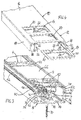
- eine perspektivische Explosionsdarstellung der Einzelteile der erfindungsgemäßen Gerätedose.
- Fig.1 1
- a perspective view of an end portion of a device box according to the invention in the assembled state with two example designed as sockets - installation devices,
- Fig. 2
- a perspective view similar to FIG. 1, but with the exclusion of certain items and with an additional mounting screw,
- Fig. 3
- a perspective view of the front end portion of the lower part only with mounted device inserts,
- Fig. 4
- a perspective view of the upper part with a separate frame part to explain the mounting and
- Figure 5
- an exploded perspective view of the items of the device box according to the invention.
In den verschiedenen Figuren der Zeichnung sind gleiche Teile stets mit den gleichen Bezugszeichen versehen.In the various figures of the drawing, like parts are always provided with the same reference numerals.
Eine erfindungsgemäße Gerätedose 1 dient gemäß Fig. 1 zur Aufnahme von mindestens einem Elektro-Installationsgerät 2, das aus einem sockelartigen Geräte-Einsatz 4 und einem Zentraleinsatz 6 besteht (siehe Fig. 2 bis 5). In der Zeichnung sind als Installationsgeräte 2 beispielhaft Steckdosen dargestellt, wobei der Zentraleinsatz 6 als sogenannter Schuko-Topf ausgebildet ist; es kann sich aber auch um Schalter unterschiedlicher Art handeln, beispielsweise Wechsel- oder Serienschalter, die als Zentraleinsatz mindestens eine Schalterwippe aufweisen. Die Gerätedose 1 besteht aus einem Dosen-Unterteil 8 zur halternden Aufnahme des Geräte-Einsatzes 4 bzw. mehrerer solcher Einsätze 4 sowie aus einem deckelartigen Dosen-Oberteil 10.A
Erfindungsgemäß ist nun das Oberteil 10 zumindest zweiteilig aus einem Deckelteil 12 und mindestens einem Rahmenteil 14 ausgebildet. Das Deckelteil 12 ist hierbei als ein von einem längeren "Endlosprofil" abgelängter Strangprofilabschnitt gebildet. Dabei besteht das Deckelteil 12 aus einem umgekehrt U-förmigen Profil mit einer oberen, ebenen Deckwandung 16 und zwei dazu im Wesentlichen senkrechten Seitenstegen 18. Für jedes vorgesehene Gerät 2 bzw. jeden in dem Unterteil 8 angerodneten Geräte-Einsatz 4 ist in der Deckwandung 16 an der entsprechenden, zumindest teilweise flächenüberdeckend oberhalb des jeweiligen Einsatzes 4 liegenden Stelle eine Geräteöffnung 20 insbesondere als Ausstanzung gebildet. Im Bereich jeder Geräteöffnung 20 ist eines der Rahmenteile 14 mit dem Deckelteil 12 unterhalb der Deckwandung 16 verbunden. Dabei umschließt jedes Rahmenteil 14 eine an die Geräteöffnung 20 sowie an den jeweiligen Zentraleinsatz 6 angepaßte Rahmenöffnung 22. Ferner sind im Bereich der Rahmenöffnung 22 nach innen in die Öffnung ragende Randstege 24 mit einer derart gerätespezifischen Randkontur vorgesehen, dass im Zusammenwirken zwischen der Rahmenöffnung 22 und dem jeweiligen Geräte-Einsatz 4 eine gegenseitige Fixierung bzw. Positionierung gewährleistet ist. Zusätzlich wirken die Randstege 24 auch mit dem jeweiligen Zentraleinsatz 6 zusammen.According to the invention, the
Für die Verbindung jedes Rahmenteils 14 mit dem Deckelteil 12 ist bevorzugt vorgesehen, dass das Deckelteil 12 auf seiner dem Unterteil 8 zugewandten Innenseite zwei seitliche, gegenüberliegende und parallel in Längsrichtung des Strangprofilabschnittes verlaufende Führungsnuten 26 aufweist, siehe hierzu insbesondere Fig. 4. Diese Führungsnuten 26 können mit Vorteil von L-förmigen Profilabschnitten 28 gebildet sein. Jedes Rahmenteil 14 ist mit zwei einander gegenüberliegenden Seitenrändern 30 (siehe Fig. 4) so in die Führungsnuten 26 einschiebbar (siehe in Fig. 4 die Pfeile 32), dass es im eingeschobenen Zustand direkt unterhalb der oberen Deckwandung 16 liegt. Jedes Rahmenteil 14 wird mit seiner Rahmenöffnung 22 im Wesentlichen deckungsgleich mit einer der Geräteöffnungen 20 positioniert und in dieser Stellung insbesondere stoffschlüssig durch einen geeigneten Klebstoff und/oder auf andere geeignete Weise fixiert.For the connection of each
Vorzugsweise ist auch das Dosen-Unterteil 8 als von einem längeren Profil abgelängter Strangprofilabschnitt gebildet. Auch dieses Profil ist im Wesentlichen U-förmig mit einem Boden 34 und zwei Seitenwänden 36 ausgebildet. Zweckmäßig ist hierbei das Oberteil 10 mit dem Unterteil 8 durch einfaches Aufsetzen verrastbar. Im dargestellten Ausführungsbeispiel weisen dazu die Seitenstege 18 des Deckelteils 12 an den Innenseiten ihrer Endkanten Raststege 38 auf, die in korrespondierende Rastnuten 40 an den Außenseiten der Seitenwände 36 des Unterteils 8 einrasten. Hierzu wird insbesondere auf Fig. 2 bis 4 verwiesen.Preferably, the
Mit Vorteil können das Deckelteil 12 und die Rahmenteile 14 aus verschiedenen Materialien bestehen. Insbesondere besteht das Deckelteil 12 als Strangpressprofil aus Aluminium, während jedes Rahmenteil 14 als Kunststoff-Formteil ausgebildet ist.Advantageously, the
Durch die bisher beschriebene Ausgestaltung ergeben sich im zusammengesetzten Zustand von Unterteil 8 und Oberteil 10 zwei gegenüberliegende offene Stirnseiten, die zweckmäßigerweise mit jeweils einem separaten, insbesondere aus Kunststoff bestehenden Stirnwandungsteil 42 verschließbar sind. Die Befestigung erfolgt insbesondere mit Schrauben 44, die durch Löcher des Stirnwandungsteils 42 in axiale Schraubkanäle 46 des Unterteils 8 einschraubbar sind.As a result of the embodiment described so far, in the assembled state of the
Weiterhin weist das Unterteil 8 zur Halterung des/jedes Geräte-Einsatzes 4 zwei gegenüberliegende Aufnahmenuten 48 zum Einsetzen von gegenüberliegenden Rändern eines sogenannten Tragringes 50 des jeweiligen Geräte-Einsatzes 4 auf.Furthermore, the
Bevorzugt weist hierbei das Unterteil 8 ein zusätzliches, inneres Einsatzprofil 52 ebenfalls in Form eines U-Profils mit einem Boden 54 und zwei Seitenwänden 56 auf, wobei bevorzugt die Aufnahmenuten 48 in den oberen Endbereichen der Seitenwände 56 des Einsatzprofils 52 gebildet sind. Durch diese Ausgestaltung können die Geräte-Einsätze 4 entweder durch axiales Einschieben der Tragringe 50 in die Aufnahmenuten 48 in Pfeilrichtung 58 gemäß Fig. 5 montiert werden, oder aber durch senkrechtes Einsetzen in Pfeilrichtung 60 unter elastischer Verformung der Seitenwände 36 bzw. 56. Die Geräte-Einsätze 4 sind grundsätzlich axial verschiebbar und können hierdurch genau in Längsrichtung positioniert werden. Die Fixierung erfolgt dann entsprechend der Anordnung der jeweiligen Geräteöffnung 20 bzw. Rahmenöffnung 22 des Oberteils 10 und durch Einsetzen des zugehörigen Zentraleinsatzes 6, der mit dem Geräte-Einsatz 4 verbunden, insbesondere verschraubt oder verrastet wird.Preferably, in this case, the
Bei der dargestellten, bevorzugten Ausführung bestehen das Unterteil 8 und das Einsatzprofil 52 aus verschiedenen Materialien, und zwar das Unterteil 8 als Stangpressprofil aus Aluminium, während das Einsatzprofil 52 elektrisch isolierend aus einem Kunststoff besteht. Dadurch wird eine elektrische Isolierung zwischen dem metallischen Unterteil 8 und den elektrischen Bestandteilen der Geräte 2 bzw. Einsätze 4 erreicht. Wie sich insbesondere aus Fig. 2 ergibt, wird das Einsatzprofil 52 mit seitlichen, sickenartigen Profilabschnitten 62 zwischen den oberen Endkanten der Seitenwände 36 des Unterteils 8 und inneren Profilstegen 64 des Oberteils 10 bzw. des Deckelteils 12 gehalten.In the illustrated, preferred embodiment, the
Im Zusammenhang damit ist es weiterhin vorteilhaft, den Innenraum des Unterteils 8 bzw. des Einsatzprofils 52 auch in Richtung des Oberteils 10 isolierend abzudecken, und zwar vor allem dann, wenn das Oberteil 10 bzw. das Deckelteil 12 aus Metall besteht. Dazu ist mindestens ein ebenes, aus einem elektrisch isolierenden Material (Kunststoff) bestehendes Wandungsteil 66 vorgesehen, welches analog zu den Tragringen 50 in die Aufnahmenuten 48 des Unterteils 8 einsetzbar ist. Hierdurch können jeweils axial neben einem Geräte-Einsatz 4 bzw. zwischen zwei Einsätzen 4 liegende Bereiche isolierend geschlossen werden; siehe insbesondere Fig. 3. Dabei fungieren die Wandungsteile 66 auch als Abstandhalter axial zwischen je zwei Geräte-Einsätzen 4.In connection therewith, it is furthermore advantageous to cover the interior of the
Zur Befestigung des Unterteils 8 auf einer Montagefläche, beispielsweise auf einer Gebäudewand, d. h. in sogenannter Aufputz-Montage (AP), sind gemäß Fig. 5 in der Bodenwandung 34 des Unterteils 8 und gegebenenfalls in dem Boden 54 des Einsatzprofils 52 Montagelöcher 68 für Montageschrauben 70 vorgesehen. Ferner ist zum Einführen eines nicht dargestellten Anschlusskabels in der Bodenwandung 34 des Unterteils 8 und gegebenenfalls in dem Boden 54 des Einsatzprofils 52 mindestens eine Durchführöffnung 72 vorhanden. Zusätzlich oder alternativ kann jedes Stirnwandungsteil 42 zur Bildung einer Kabel-Einführöffnung ein abtrennbares (herausbrechbares) Wandungsstück 74 aufweisen.For fixing the
Die Erfindung ist nicht auf die dargestellten und beschriebenen Ausführungsbeispiele beschränkt, sondern umfaßt auch alle im Sinne der Erfindung gleichwirkenden Ausführungen. Ferner ist die Erfindung bislang auch noch nicht auf die im Anspruch 1 definierte Merkmalskombination beschränkt, sondern kann auch durch jede beliebige andere Kombination von bestimmten Merkmalen aller insgesamt offenbarten Einzelmerkmalen definiert sein. Dies bedeutet, daß grundsätzlich praktisch jedes Einzelmerkmal des Anspruchs 1 weggelassen bzw. durch mindestens ein an anderer Stelle der Anmeldung offenbartes Einzelmerkmal ersetzt werden kann. Insofern ist der Anspruch 1 lediglich als ein erster Formulierungsversuch für eine Erfindung zu verstehen.The invention is not limited to the illustrated and described embodiments, but also includes all the same in the context of the invention embodiments. Furthermore, the invention has hitherto not been limited to the feature combination defined in
Claims (17)
dadurch gekennzeichnet, dass dasOberteil(10)auseinemvon einem Strangprofilabschnitt gebildeten und in einer oberen Deckwandung (16) mindestens eine Geräteöffnung (20) aufweisenden Deckelteil (12) besteht, wobei im Bereich der bzw. jeder Geräteöffnung (20) ein gesondertes Rahmenteil (14) mit dem Deckelteil (12) verbunden ist.Device socket (1) for receiving at least one electrical installation device (2), such as switches, socket and / or the like, consisting of a - can be fixed - in particular in so-called surface mounting on a mounting surface to be mounted - lower part (8) for retaining holder at least one device insert (4) and a lid-like can top (10),
characterized in that the upper part (10) consists of a cover part (12) formed by an extruded profile section and having at least one device opening (20) in an upper cover wall (16), a separate frame part (14) being provided in the region of the or each device opening (20). is connected to the lid part (12).
dadurch gekennzeichnet, dass das/jedesRahmenteil(14)eine an die Geräteöffnung (20) und an einen mit dem Geräte-Einsatz (4) zu verbindenden Zentraleinsatz (6) angepasste Rahmenöffnung (22) umschließt und im Bereich der Rahmenöffnung (22) Randstege (24) mit einer gerätespezifischen Randkontur vorgesehen sind.Device socket according to claim 1,
characterized in that the / each frame part (14) encloses a frame opening (22) adapted to the appliance opening (20) and to a central insert (6) to be connected to the appliance insert (4) and edge bars (22) in the area of the frame opening (22). 24) are provided with a device-specific edge contour.
dadurch gekennzeichnet, dass dasDeckelteil(12)aufseiner dem Unterteil (8) zugewandten Innenseite zwei gegenüberliegende und parallel in Längsrichtung des Strangprofilabschnittes verlaufende Führungsnuten (26) aufweist, wobei das/jedes Rahmenteil (14) mit zwei einander gegenüberliegenden Seitenrändern (30) so in die Führungsnuten (26) eingesetzt und im Bereich der zugehörigen Geräteöffnung (20) fixiert ist, dass es unterhalb der oberen Deckwandung (16) liegt.Device box according to claim 1 or 2,
characterized in that the cover part (12) has on its inner side facing the lower part (8) two opposite guide grooves (26) extending parallel in the longitudinal direction of the extruded section, the / each frame part (14) having two opposite side edges (30) in the Guide grooves (26) is inserted and fixed in the region of the associated device opening (20) that it lies below the upper cover wall (16).
dadurch gekennzeichnet, dass das/jedesRahmenteil(14)an dem Deckelteil (12) bzw. an der Innenseite der Deckwandung (16) stoffschlüssig fixiert ist.Device socket according to one of claims 1 to 3,
characterized in that the / each frame part (14) on the cover part (12) or on the inside of the top wall (16) is firmly bonded.
dadurch gekennzeichnet, dass dasOberteil(10)mitdem Unterteil (8) verrastbar ist.Device socket according to one of claims 1 to 4,
characterized in that the upper part (10) can be latched to the lower part (8).
dadurch gekennzeichnet, dass dasDeckelteil(12)anbeiden Längsrändern der oberen Deckwandung (16) Seitenstege (18) aufweist, die das Unterteil (8) teilweise übergreifend mit diesem verrastbar sind.Device socket according to one of claims 1 to 5,
characterized in that the cover part (12) has at both longitudinal edges of the upper cover wall (16) side webs (18) which are the cross-member (8) partially overlapping with this latched.
dadurch gekennzeichnet, dass das Deckelteil (12) als Strangpressprofil insbesondere aus Aluminium besteht.Device socket according to one of claims 1 to 6,
characterized in that the cover part (12) consists of an extruded profile, in particular made of aluminum.
dadurch gekennzeichnet, dass das/jedesRahmenteil(14)als Formteil insbesondere aus Kunststoff besteht.Device socket according to one of claims 1 to 7,
characterized in that the / each frame part (14) as a molded part, in particular made of plastic.
dadurch gekennzeichnet, dass das Unterteil (8) von einem Strangprofilabschnitt gebildet ist.Device socket according to one of claims 1 to 8,
characterized in that the lower part (8) is formed by an extruded profile section.
dadurch gekennzeichnet, dass gegenüberliegende offene Stirnseiten von Unterteil (8) und Oberteil (10) mit jeweils einem separaten, insbesondere aus Kunststoff bestehenden Stirnwandungsteil (42) verschlossenen bzw. verschließbar sind.Device socket according to one of claims 1 to 9,
characterized in that opposite open end faces of the lower part (8) and upper part (10) each having a separate, in particular made of plastic Stirnwandungsteil (42) are closed or closed.
dadurch gekennzeichnet, dass das Unterteil (8) zur Halterung des/jedes Geräte-Einsatzes (4) zwei gegenüberliegende Aufnahmenuten (48) zum Einsetzen von gegenüberliegenden Rändern eines Tragringes (50) des Geräte-Einsatzes (4) aufweist.Device socket according to one of claims 1 to 10,
characterized in that the lower part (8) for holding the / each device insert (4) has two opposite receiving grooves (48) for insertion of opposite edges of a support ring (50) of the device insert (4).
dadurch gekennzeichnet, dass das Unterteil (8) ein zusätzliches, inneres Einsatzprofil (52) aufweist, wobei vorzugsweise das Einsatzprofil (52) die Aufnahmenuten (48) zur Tragring-Halterung aufweist.Device socket according to one of claims 1 to 11,
characterized in that the lower part (8) has an additional, inner insert profile (52), preferably wherein the insert profile (52) bearing ring holder having the receiving grooves (48) for.
dadurch gekennzeichnet, dass das Unterteil (8) und das Einsatzprofil (52) aus verschiedenen Materialien bestehen, und zwar insbesondere das Unterteil (8) als Strangpressprofil aus Aluminium und das Einsatzprofil (52) aus Kunststoff.Device socket according to claim 12,
characterized in that the lower part (8) and the insert profile (52) consist of different materials, in particular the lower part (8) as an extruded aluminum profile and the insert profile (52) made of plastic.
gekennzeichnet durch mindestens ein ebenes, aus einem elektrisch isolierenden Material bestehendes Wandungsteil (66) zum Einsetzen in die Aufnahmenuten (48) des Unterteils (8) jeweils in einem einem Geräte-Einsatz (4) in Profillängsrichtung benachbarten Bereich des Unterteils (8).Device box according to one of claims 11 to 13,
characterized by at least one planar, consisting of an electrically insulating material wall portion (66) for insertion into the receiving grooves (48) of the lower part (8) each in a device insert (4) in the profile longitudinal direction adjacent region of the lower part (8).
dadurch gekennzeichnet, dass das Unterteil (8) zur Befestigung auf der Montagefläche in einer ebenen Bodenwandung (34) Montagelöcher (68) für Montageschrauben (70) aufweist.Device socket according to one of claims 1 to 14,
characterized in that the lower part (8) for mounting on the mounting surface in a flat bottom wall (34) has mounting holes (68) for mounting screws (70).
Applications Claiming Priority (1)
| Application Number | Priority Date | Filing Date | Title |
|---|---|---|---|
| DE202005003068U DE202005003068U1 (en) | 2005-02-25 | 2005-02-25 | Device socket for electrical installation devices |
Publications (2)
| Publication Number | Publication Date |
|---|---|
| EP1701422A1 true EP1701422A1 (en) | 2006-09-13 |
| EP1701422B1 EP1701422B1 (en) | 2008-04-02 |
Family
ID=35974666
Family Applications (1)
| Application Number | Title | Priority Date | Filing Date |
|---|---|---|---|
| EP06110352A Active EP1701422B1 (en) | 2005-02-25 | 2006-02-23 | Apparatus box for electrical installation device |
Country Status (3)
| Country | Link |
|---|---|
| EP (1) | EP1701422B1 (en) |
| AT (1) | ATE391356T1 (en) |
| DE (2) | DE202005003068U1 (en) |
Cited By (2)
| Publication number | Priority date | Publication date | Assignee | Title |
|---|---|---|---|---|
| DE202007017167U1 (en) | 2007-12-08 | 2009-04-16 | Tehalit Gmbh | Device holder for universal attachment of installation devices and devices to cable trunking |
| CN106165227A (en) * | 2013-11-29 | 2016-11-23 | 伊顿保护系统Ip有限两合公司 | Container |
Families Citing this family (2)
| Publication number | Priority date | Publication date | Assignee | Title |
|---|---|---|---|---|
| DE202007012406U1 (en) | 2007-09-04 | 2009-01-08 | Tehalit Gmbh | Device holder for fastening electrical installation devices to a cable trunking |
| DE102019122500A1 (en) * | 2019-08-21 | 2021-02-25 | WASAG brush systems AG | Wall or floor bar with integrated cable duct and method for installing such a wall or floor bar |
Citations (4)
| Publication number | Priority date | Publication date | Assignee | Title |
|---|---|---|---|---|
| GB2229869A (en) * | 1989-02-03 | 1990-10-03 | Ackermann Electrical Syst | Improvements in and relating to the mounting of electrical accessories |
| EP0630092A1 (en) * | 1993-06-14 | 1994-12-21 | Aparellaje Electrico, S.A. | Electrical mechanism support device in trays for electrical ducting |
| US5379972A (en) * | 1992-12-01 | 1995-01-10 | Legrand | Equipment support adapted to be attached to the body of trunking with inwardly facing lips |
| US6384336B1 (en) * | 1999-04-22 | 2002-05-07 | Panduit Corp. | Device bracket |
-
2005
- 2005-02-25 DE DE202005003068U patent/DE202005003068U1/en not_active Expired - Lifetime
-
2006
- 2006-02-23 EP EP06110352A patent/EP1701422B1/en active Active
- 2006-02-23 DE DE502006000542T patent/DE502006000542D1/en active Active
- 2006-02-23 AT AT06110352T patent/ATE391356T1/en active
Patent Citations (4)
| Publication number | Priority date | Publication date | Assignee | Title |
|---|---|---|---|---|
| GB2229869A (en) * | 1989-02-03 | 1990-10-03 | Ackermann Electrical Syst | Improvements in and relating to the mounting of electrical accessories |
| US5379972A (en) * | 1992-12-01 | 1995-01-10 | Legrand | Equipment support adapted to be attached to the body of trunking with inwardly facing lips |
| EP0630092A1 (en) * | 1993-06-14 | 1994-12-21 | Aparellaje Electrico, S.A. | Electrical mechanism support device in trays for electrical ducting |
| US6384336B1 (en) * | 1999-04-22 | 2002-05-07 | Panduit Corp. | Device bracket |
Cited By (4)
| Publication number | Priority date | Publication date | Assignee | Title |
|---|---|---|---|---|
| DE202007017167U1 (en) | 2007-12-08 | 2009-04-16 | Tehalit Gmbh | Device holder for universal attachment of installation devices and devices to cable trunking |
| EP2068410A1 (en) | 2007-12-08 | 2009-06-10 | Tehalit GmbH | Device holder for universally fixing installation devices and machines to wiring channels |
| CN106165227A (en) * | 2013-11-29 | 2016-11-23 | 伊顿保护系统Ip有限两合公司 | Container |
| CN106165227B (en) * | 2013-11-29 | 2018-11-23 | 伊顿保护系统Ip有限两合公司 | Container |
Also Published As
| Publication number | Publication date |
|---|---|
| ATE391356T1 (en) | 2008-04-15 |
| DE502006000542D1 (en) | 2008-05-15 |
| DE202005003068U1 (en) | 2006-07-06 |
| EP1701422B1 (en) | 2008-04-02 |
Similar Documents
| Publication | Publication Date | Title |
|---|---|---|
| EP3292604B1 (en) | Method for producing a wall lead-through for a plurality cables and arrangement | |
| EP2996120B1 (en) | Support device for a ring core choke and inductive component | |
| EP1701422B1 (en) | Apparatus box for electrical installation device | |
| DE4036249A1 (en) | Duct made of e.g. steel sheet for accommodating electrical installation units - has lid type upper part permitting detachment and units for attaining potential equalisation between duct parts | |
| EP0957552B1 (en) | Box for electrical apparatus | |
| EP0722208B1 (en) | Device for flushmounting an electrical installation apparatus | |
| EP2650994B1 (en) | Socket assembly for device installation assemblies with a holding rail at the channel base and device installation channel comprising such a socket assembly | |
| DE102017006870A1 (en) | Electrical installation device | |
| EP1798831A2 (en) | Electrical installation device | |
| DE3503412A1 (en) | CONNECTOR FOR CONNECTING A MULTI-WIRE ELECTRIC FLAT CABLE TO OTHER CIRCUIT ELEMENTS | |
| EP1394915B1 (en) | Cable guide | |
| EP3836305B1 (en) | Connection device for a shielded conductor of an electrical cable | |
| EP3045617B1 (en) | Rosette and assembly of a door or window handle and a rosette on a receiving opening of a door leaf, a window leaf or the like | |
| DE2946114A1 (en) | Housing for circuit components - has plastics ends with plastics base and lid sections cut to length | |
| DE19530241A1 (en) | Threadless clamp insertable into insulating housing for coupling electric conducting | |
| EP2690729A1 (en) | Electrical installation system and dry wall box for electric installation | |
| EP2639912B1 (en) | Device installation socket for device installation channels and device installation channel comprising same | |
| DE2037779B2 (en) | Water-protected surface box | |
| EP2106005B1 (en) | Supply unit for under-floor usage | |
| DE102008015770B4 (en) | Supply unit for underfloor application | |
| DE102007029247B3 (en) | Device base of an installation device for receiving electrical contact parts | |
| DE4334554C2 (en) | Box for electrical installations | |
| DE2427476C3 (en) | Electrical switching equipment | |
| EP1098411A1 (en) | Covering frame for electrical installation apparatus | |
| DE8406177U1 (en) | Cable routing or cable duct |
Legal Events
| Date | Code | Title | Description |
|---|---|---|---|
| PUAI | Public reference made under article 153(3) epc to a published international application that has entered the european phase |
Free format text: ORIGINAL CODE: 0009012 |
|
| 17P | Request for examination filed |
Effective date: 20060623 |
|
| AK | Designated contracting states |
Kind code of ref document: A1 Designated state(s): AT BE BG CH CY CZ DE DK EE ES FI FR GB GR HU IE IS IT LI LT LU LV MC NL PL PT RO SE SI SK TR |
|
| AX | Request for extension of the european patent |
Extension state: AL BA HR MK YU |
|
| AKX | Designation fees paid |
Designated state(s): AT DE NL |
|
| GRAP | Despatch of communication of intention to grant a patent |
Free format text: ORIGINAL CODE: EPIDOSNIGR1 |
|
| GRAS | Grant fee paid |
Free format text: ORIGINAL CODE: EPIDOSNIGR3 |
|
| GRAA | (expected) grant |
Free format text: ORIGINAL CODE: 0009210 |
|
| AK | Designated contracting states |
Kind code of ref document: B1 Designated state(s): AT DE NL |
|
| REF | Corresponds to: |
Ref document number: 502006000542 Country of ref document: DE Date of ref document: 20080515 Kind code of ref document: P |
|
| PLBE | No opposition filed within time limit |
Free format text: ORIGINAL CODE: 0009261 |
|
| STAA | Information on the status of an ep patent application or granted ep patent |
Free format text: STATUS: NO OPPOSITION FILED WITHIN TIME LIMIT |
|
| 26N | No opposition filed |
Effective date: 20090106 |
|
| PGFP | Annual fee paid to national office [announced via postgrant information from national office to epo] |
Ref country code: AT Payment date: 20230127 Year of fee payment: 18 |
|
| PGFP | Annual fee paid to national office [announced via postgrant information from national office to epo] |
Ref country code: NL Payment date: 20230127 Year of fee payment: 18 |
|
| P01 | Opt-out of the competence of the unified patent court (upc) registered |
Effective date: 20230525 |
|
| PGFP | Annual fee paid to national office [announced via postgrant information from national office to epo] |
Ref country code: DE Payment date: 20230420 Year of fee payment: 18 |