EP1701335B1 - Action for piano - Google Patents
Action for piano Download PDFInfo
- Publication number
- EP1701335B1 EP1701335B1 EP06002732A EP06002732A EP1701335B1 EP 1701335 B1 EP1701335 B1 EP 1701335B1 EP 06002732 A EP06002732 A EP 06002732A EP 06002732 A EP06002732 A EP 06002732A EP 1701335 B1 EP1701335 B1 EP 1701335B1
- Authority
- EP
- European Patent Office
- Prior art keywords
- jack
- contact surface
- hammer
- regulating button
- action
- Prior art date
- Legal status (The legal status is an assumption and is not a legal conclusion. Google has not performed a legal analysis and makes no representation as to the accuracy of the status listed.)
- Active
Links
Images


Classifications
-
- G—PHYSICS
- G10—MUSICAL INSTRUMENTS; ACOUSTICS
- G10C—PIANOS, HARPSICHORDS, SPINETS OR SIMILAR STRINGED MUSICAL INSTRUMENTS WITH ONE OR MORE KEYBOARDS
- G10C3/00—Details or accessories
- G10C3/16—Actions
- G10C3/161—Actions specially adapted for upright pianos
-
- G—PHYSICS
- G10—MUSICAL INSTRUMENTS; ACOUSTICS
- G10C—PIANOS, HARPSICHORDS, SPINETS OR SIMILAR STRINGED MUSICAL INSTRUMENTS WITH ONE OR MORE KEYBOARDS
- G10C1/00—General design of pianos, harpsichords, spinets or similar stringed musical instruments with one or more keyboards
- G10C1/02—General design of pianos, harpsichords, spinets or similar stringed musical instruments with one or more keyboards of upright pianos
-
- G—PHYSICS
- G10—MUSICAL INSTRUMENTS; ACOUSTICS
- G10C—PIANOS, HARPSICHORDS, SPINETS OR SIMILAR STRINGED MUSICAL INSTRUMENTS WITH ONE OR MORE KEYBOARDS
- G10C9/00—Methods, tools or materials specially adapted for the manufacture or maintenance of musical instruments covered by this subclass
Landscapes
- Physics & Mathematics (AREA)
- Engineering & Computer Science (AREA)
- Acoustics & Sound (AREA)
- Multimedia (AREA)
- Electrophonic Musical Instruments (AREA)
Description
- The present invention relates to an action for a piano which actuates in response to a depression on an associated key to swing a hammer which in turn strikes a string.
- A known conventional action for a piano is disclosed, for example, in Laid-open
Japanese Patent Application No. 6-83326 action 51 in a key released state. Theaction 51 is adapted for an upright piano, and is disposed above the rear end of a key 50 (the left-hand side in Fig. 1 is assumed to be the rear side). Theaction 51 comprises awippen 52 carried on the rear end of thekey 50; ajack 53 pivotably arranged on thewippen 52; and a regulatingbutton 56 disposed at a predetermined position above thewippen 52. Thejack 53 is formed in L-shape with a regulatingbutton contact protrusion 54 extending in the front-to-rear direction, and a hammer push-uprod 55 extending upward substantially at right angles with the rear end of the regulatingbutton contact protrusion 54, and is pivotably supported by thewippen 52 at the corner of bothmembers up rod 55 is in engagement with abat 61 of ahammer 60, and the regulatingbutton contact protrusion 54 has a regulatingbutton contact surface 54a opposing a regulatingbutton 56 from below. The regulatingbutton contact surface 54a is formed in a curved surface. Thebat 61 is arranged such that ahammer shank 62 extends upward therefrom, and a hammer head (not shown) of thehammer 60 is mounted to the upper end of thehammer shank 62. Also, thebat 61 is provided with abat spring 61a for urging thehammer 60 in the clockwise direction in Fig. 1. - As the
key 50 is depressed in the upright piano as described above, thewippen 52 is pushed up by the rear end of thekey 50 to pivotally move upward, causing thejack 53 to move up together with thewippen 52. In this way, thehammer 60 is pushed up by thejack 53 through thebat 61, and pivotally moves toward a vertically stretched string (not shown) in the rear against an urging force of thebat spring 61a. Then, as the regulatingbutton contact protrusion 54 of thejack 53 comes into contact with a regulatingbutton 56, thejack 53 is prevented from moving up. As thewippen 52 further pivotally moves , the regulatingbutton contact protrusion 54 of thejack 53 pivotally moves with respect to thewippen 52 while sliding along the lower surface of the regulatingbutton 56, with a counter-force from the regulatingbutton 56 acting on thejack 53, resulting in thejack 53 coming off thehammer 60. Consequently, the weight of thehammer 60 is lost from a touch weight (a load applied on a finger tip) of thekey 50, giving a let-off feeling to a player. After thejack 53 has come off thehammer 60, thehammer 60 strikes an associated string with the inertia. - Generally, for rich play representations, it is important to correctly pinpoint a timing at which the
jack 53 comes off thehammer 60, i.e. , a let-off timing to finely adjust the speed at which thehammer 60 strikes the string. For example, a weak sound such as pianissimo can be generated by once bringing thehammer 60 to the vicinity of the string and letting it swing from that position to reduce the string striking speed of thehammer 60. In other words, a weak sound can be generated by once depressing thekey 50 to immediately before let-off at which thejack 53 comes off thehammer 60, and pushing down thekey 50 from that state. - On the other hand, in the upright piano which employs the conventional action, the
hammer shank 62 extends vertically as mentioned above, so that the center of gravity of thehammer 60 is positioned near the fulcrum of its swinging movements, resulting in small moment about the fulcrum of the swinging movements produced by the self weight of thehammer 60. For this reason, a let-off load, which is a touch weight immediately before the let-off, is relatively small, and the touch weight varies only by a small amount before and after the let-off, thus experiencing difficulties in pinpointing the timing of the let-off. As a result, the piano is degraded in its capabilities of expressions and playing performance due to difficulties in finely adjusting the string striking speed of thehammer 60. - Also, high sequentially touching capabilities are also required for rich playing expressions. In a grand piano, the hammer extends substantially horizontally, with its center of gravity positioned near a hammer head spaced largely from the fulcrum of pivotal movements at one end of the hammer in the horizontal direction. Thus, the hammer, after striking a string above, promptly swings by its own weight to return to a position at which it can be again pushed up by the jack, with the result that the grand piano provides high sequentially touching capabilities. On the other hand, in the aforementioned upright piano, since the
hammer 60, after striking the string, is swung by an urging force of thebat spring 61a to return, a relatively long time is taken for thehammer 60 andjack 53 to return to a state in which thehammer 60 can be again pushed up, resulting in lower sequentially touching capabilities of the upright piano than the grand piano. For improving the sequentially touching capabilities of the upright piano, it is contemplated to enhance the spring force of thebat spring 61a to reduce a time for thehammer 60 to swing back to the position at which it can be again pushed up by thejack 53. In this strategy, however, the touch weight is increased by the enhanced spring force when thehammer 60 is pushed up by thejack 53, resulting in adverse affections exerted on the touch feeling. - Document
GB 174390 A - Document
US 5272950 A teaches a striking mechanism, wherein said power for the key is transferred to a hammer via rod system which is so adapted that a connection of the key and the hammer is never Interrupted. - Document
US 3583271 A reveals a piano action, wherein major components of the action, including a wippen, a hammer butt, a hammer jack, a damper lever, a back check and a mounting flange are molded from plastic, whereby the construction of the parts eliminate completely the necessity for drilled holes In the parts to receive center pins, spoon shafts and other members normally received In drilled holes. - The present invention has been made to solve the problem as mentioned above, and it is an object of the invention to provide an action for a piano which is capable of clarifying a timing of let-off, improving the sequentially touching capabilities, and consequently realizing high playing performance excellent in expressive power in a simple structure without adversely affecting the key touch feeling.
- To achieve the above object, the present invention provides an action for a piano, configured to actuate in response to a depression on a key to swing a hammer which strikes a string. The action is characterized by comprising a wippen pushed up by the key when the key is depressed to pivotally move upward; a regulating button having a flat jack contact surface on a lower end, and fixed to a predetermined position above the wippen; and a jack having a regulating button contact protrusion including a flat regulating button contact surface on an upper end, and arranged on the wippen for pivotal movement about a jack fulcrum to engage with the hammer such that a pivotal movement of the wippen causes the jack to push up the hammer, wherein the jack is configured to pivotally move relative to the wippen to come off the hammer by the regulating button contact surface coming into contact with the jack contact surface during the pivotal movement, and a sheeted damping material on at least one of said jack contact surface or said regulating button contact surface;
wherein said regulating button contact surface is angled such that when said regulating button contact surface comes into contact with said lack contact surface through said damping material, said regulating button contact surface comes Into contact with an end of said Jack contact surface close to said Jack fulcrum, and said regulating button contact surface extends obliquely in close proximity to said jack contact surface. - According to the action for a piano described above, the jack is in engagement with the hammer in a key released state. As the key is depressed from this state, the wippen is pushed up by the key to pivotally move upward, and the jack moves up together with the wippen. In this way, the hammer is pushed up by the jack to swing. During this pivotal movement of the wippen, the regulating button contact surface of the jack comes into contact with the jack contact surface of the regulating button, thereby preventing the jack from moving up. Then, as the wippen pivotally moves more and more, the jack pivotally moves relative to the wippen, while the regulating button contact protrusion is sliding along the jack contact surface, with a counter-force acting on the jack from the regulating button. When the pivotal movement reaches a predetermined amount, the jack comes off the hammer. Subsequently, the hammer swings with inertia to strike a string.
- As described above, after coming into contact with the regulating button, the jack pivotally moves relative to the wippen, while its regulating button contact protrusion is sliding along the jack contact surface, with the counter-force acting from the regulating button. The counter-force of the regulating button in this event is transmitted to the key through the jack and wippen, resulting in a corresponding increase in touch weight. In this sequence of operations, since both the regulating button contact surface and jack contact surface are both flat in the present invention, the regulating button contact surface comes into planar contact with the jack contact surface, to increase the contact area of both, as compared with the aforementioned conventional regulating button contact surface which is curved, resulting in a larger frictional resistance between the regulating button contact protrusion and the regulating button. This makes the regulating button contact protrusion difficult to slide along the jack contact surface to cause consequent difficulties in the pivotal movement of the jack. Thus, the counter-force of the regulating button, transmitted through the jack and wippen, is further increasing until the jack comes off. This results in a larger touch weight immediately before let-off, i.e., a larger let-off load, and a larger amount of change in the touch weight before and after the let-off, thereby making it possible to clarify the timing of the let-off. In response to the thus clarified timing of the let-off, the player can finely adjust a string striking speed of the hammer to realize high playing performance excellent in expressive power. Also, the foregoing advantageous effects can be provided in a simple structure only including the flat jack contact surface and flat regulating button contact surface.
- According to this preferred embodiment of the action for a piano, during a pivotal movement of the wippen associated with a depression on the key, the regulating button contact surface of the regulating button contact protrusion comes into contact with the jack contact surface through the sheeted damping material, causing the jack to pivotally move relative to the wippen. Also, when this contact is made, the regulating button contact surface comes into contact with the end of the jack close to the jack fulcrum, and extends obliquely in close proximity to the jack contact surface, i.e.. comes into contact with the jack contact surface at a slight angle formed thereto. In this event, as the intervening sheeted damping material is compressed, a combination of the end of the regulating button contact surface close to the jack fulcrum and its vicinity is in contact with planar contact with the jack contact surface through the damping material, thereby ensuring a larger frictional resistance. Further, such a planar contact causes the center of the planar contact, i. e. , a point acted by the counter-force from the regulating point, to be near the jack fulcrum, resulting in a larger counter-force of the regulating button required for the pivotal movement of the jack. Thus, according to the present invention, the let-off load is increased by a larger frictional resistance ensured by the planar contact, and the counter-force of the regulating button acting on a position closer to the jack fulcrum, thus ensuring the advantageous effects of the action described above.
- Preferably, in the action for a piano described above, the regulating button contact surface is angled such that the regulating button contact surface comes into planar contact with the jack contact surface.
- According to this preferred embodiment of the action for a piano, the regulating button contact surface comes into tightly planar contact with the jack contact surface without fail. This causes the generation of a large frictional resistance between the regulating button contact protrusion and the regulating button, which makes the jack difficult to pivotally move, and increases the let-off load, thus making it possible to ensure the advantageous effects mentioned above.
- Preferably, in the action for a piano described above, the jack includes a hammer push-up rod extending upward from the jack fulcrum, and configured to engage with the hammer, and the hammer push-up rod includes a prominence formed along an edge of a top surface thereof opposite to the regulating button contact protrusion.
- According to this preferred embodiment of the action for a piano, the top surface of the hammer push-up rod, extending upward from the jack fulcrum, slides along the bottom of the hammer toward the regulating button in association with the pivotal movement of the jack which Is accompanied with a depression on the key. Also, since the prominence is formed along an edge of a top surface thereof opposite to the regulating button contact protrusion, this prominence serves as a resistance when the jack slides along the hammer, thus making the jack difficult to come off the hammer. This can result in a further increase in the let-off load and a more clarified timing of the let-off.
- Preferably, in the action for a piano described above, the jack comprises a molding formed of a synthetic resin.
- According to this preferred embodiment of the action for a piano, the jack can be molded with a high accuracy, and therefore, the regulating button contact surface and the prominence on the hammer push-up rod can be readily formed into respective desired shapes with a high accuracy, and a desired relationship can be readily established in the position and angle with respect to the jack contact surface. Also, since the jack is made of a synthetic resin, advantages of the synthetic resin can be provided, including a high machining accuracy and dimensional stability.
- Preferably, in the action for a piano described above, the jack comprises a molding molded by a long-staple method and made of a thermoplastic resin containing long fibers for reinforcement.
- According to this preferred embodiment of the action for a piano, the jack comprises a molding molded by the long-staple method and made of a thermoplastic resin containing long fibers for reinforcement. Here, the long-staple method involves injection molding of a pellet containing fibrous reinforcing materials of the same length covered with a thermoplastic resin to produce moldings. According to the long-staple method, relatively long fibrous reinforcing materials having a length of 0.5 mm, for example, are contained in the moldings. Thus, the jack contains the relatively long fibers for reinforcement and can accordingly exhibit a very high rigidity, as compared with a jack made of a synthetic resin.
- As a result, the jack can be reduced in weight than before, while ensuring a required rigidity. In this event, since the jack can be rapidly returned to a state in which it can again push up the hammer in response to a released key, the sequentially touching capabilities can be improved to realize high playing performance excellent in expressive power, without adversely affecting a touch feeling of the key.
- Preferably, in the action for a piano described above, the long fibers are carbon fibers.
- Dust sticking to movable parts of the action can cause their slow motions which can degrade the responsibility of the action. Also, in general, the carbon fiber is more electrically conductive than other long fibers for reinforcement, for example, glass fiber. Thus, by containing such carbon fibers in the thermoplastic resin, by which the jack is made, as long fibers for reinforcement, the jack can be improved in conductivity to reduce its electrostatic property. Consequently, since the reduced electrostatic property restrains dust from stacking to the jack, the jack can provide consistently good movements and responsibility. Also, the dust restrained from sticking to the jack can keep the appearance of the jack clear and prevent the operator's hands and clothing from being soiled in operations for adjusting the action and the like.
- Preferably, in the action for a piano described above , the thermoplastic resin is an ABS resin.
- Since the ABS resin exhibits a small molding contraction ratio among resins, the use of the ABS resin can improve the machining accuracy and restrain variations in dimensions of the respective jacks.
- Generally, when a thermoplastic resin containing a reinforcing material such as carbon fiber is injection molded at a high melt flow rate, the thermoplastic resin flows into a mold at higher speeds, causing a higher susceptibility to anisotropy in rigidity of the molding due to the reinforcing material tending to align in a particular direction in the molding. The ABS resin is a thermoplastic resin containing a rubber-like polymer, and can be molded at a low melt flow rate. Accordingly, when the jack is made of the ABS resin as described above, the jack can be restrained in anisotropy and consistently provide a high rigidity. Further, the ductility exhibited by the ABS resin can enhance the impact strength of the jack.
- Fig. 1 is a side view illustrating main components of a conventional action in a key released state;
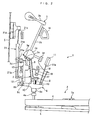
- Fig. 2 is a side view illustrating an action according to a first embodiment of the present invention together with associated components in a key released state;
- Fig. 3 is a partially enlarged view illustrating a jack of the action in Fig. 2 together with associated components in the key released state;
- Fig. 4 is a side view illustrating the jack of the action in Fig. 2 together with associated components when a regulating button contact surface comes into contact with a jack contact surface through a punching;
- Fig. 5 is a partially enlarged view of Fig. 4;
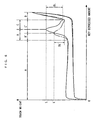
- Fig. 6 is a diagram showing the relationship between a key depressed amount and a touch weight when the action of Fig. 2 is used, together with a comparative example;
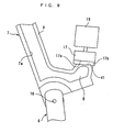
- Fig. 7 is a side view illustrating a jack of an action according to a second embodiment together with associated components in a key released state;
- Fig. 8 is a partially enlarged view of a hammer push-up rod in Fig. 7; and
- Fig. 9 is a partially enlarged side view illustrating a jack of an action according to a third embodiment together with associated components when a regulating button contact surface comes into contact with a jack contact surface through a punching.
- In the following, an action according to one embodiment of the present invention will be described with reference to the accompanying drawings.
- Fig. 2 illustrates an
action 1, akeyboard 2, ahammer 3 and the like of an upright piano according to a first embodiment of the present invention in a key released state. Thekeyboard 2 comprises a large number of keys 4 (only one of which is shown) arranged side by side from left to right (in a depth direction in Fig. 2), and each key 4 is swingably supported by a fulcrum which is abalance pin 5a implanted on akeybed 5. - The
action 1 is attached to a left and a right bracket (none of which is shown) arranged at a left and a right end of thekeybed 5 above the rear end of thekeyboard 2, and arranged to extend between both the brackets.Theaction 1 also comprises awippen 6 and ajack 7 which are provided for each key 4 (only one each of them is shown). Further, acenter rail 15 and ahammer rail 16 are extended between the left and right brackets. - The
wippen 6, which is formed, for example, of synthetic resin in a predetermined shape, has a heel 6a extending downward from the front, and is carried on acapstan button 4a arranged on the top surface of a corresponding key 4 in a rear end area through the heel 6a. Thewippen 6 is pivotably attached to awippen flange 6b fixed on thecenter rail 15 through a pin-shapedfulcrum 6c. Aback check wire 11a is implanted on the top surface of thewippen 6 in a front end area, and aback check 11 is attached to a leading end thereof. Aspoon 12 is also implanted on thewippen 6 in an area behind thefulcrum 6c for driving adamper 21, later described. - The
jack 7, which is formed by a long-staple method, is injection molded using a pellet as described below. This pellet is manufactured by covering lobings made of carbon fiber with a thermoplastic resin containing a rubber-like polymer, for example, an ABS resin, which is one type of synthetic resin, extruded by an extruder, while the lobings are made even with a predetermined tension applied thereto. In this way, the lobings of carbon fiber can be contained in the pellet when it is molded without bending the lobings, so that the pellet contains carbon fibers which are equal in length to the pellet. In this embodiment, the length of the pellet is set in a range of 5 to 15 mm, whereby carbon fibers of 0.5 to 2 mm long are contained in thejack 7 which is injection molded using the pellet. A melt flow rate is set to a relatively small value for the aforementioned rubber-like polymer, for example, in a range of 0.1 to 50 g per 10 minutes under a testing condition including the temperature of 230 °C and a load of 2.12 kg. - The
jack 7, which is formed in an L-shape by the long-staple method as described above, comprises a regulatingbutton contact protrusion 8 extending in a front-to-back direction, and a hammer push-uprod 9 extending upward from the rear end of the regulatingbutton contact protrusion 8 and longer than the regulatingbutton contact protrusion 8, as illustrated in Fig. 3. Also, thejack 7 is pivotably attached at a central area of thewippen 6 through a pin-shapedjack fulcrum 10 at the corner between the regulatingbutton contact protrusion 8 and the hammer push-uprod 9. The regulatingbutton contact protrusion 8 has a front end which slightly protrudes upward, and a top end which serves as a flat regulatingbutton contact surface 8a that is inclined at a predetermined angle, as will be later described. Also, thejack 7 is formed with arecess 7a substantially entirely on each of the left and right side surfaces for reducing the weight. Ajack spring 13 is provided between the regulatingbutton contact protrusion 8 of thejack 7 and thewippen 6 for returning thejack 7 when the key 4 is released. - A
regulating button 17 is arranged above the regulatingbutton contact protrusion 8 of thejack 7. Theregulating button 17 is provided for each key 4 through a plurality of regulating brackets 18 (only one of which is shown) disposed on thecenter rail 15, and a regulatingrail 19 which is attached to the front end thereof and extends from left to right. The lower end of theregulating button 17 serves as a flatjack contact surface 17a which opposes the regulatingbutton contact surface 8a of thejack 7 in the key released state. Thejack contact surface 17a slightly inclines downward in front at a predetermined angle to the horizontal line. Asheeted punching 17b (damping material) made, for example, of felt is adhered to thejack contact surface 17a. - The
hammer 3 comprises a bat 3a, ahammer shank 3b, and a hammer head 3c. The bat 3a is pivotably attached to abat flange 3d fixed to thecenter rail 15 through a pin-shapedfulcrum 3e, thereby permitting thehammer 3 to swing. Thehammer shank 3b extends upward from the bat 3a, and the hammer head 3c is attached to the upper end thereof. In the key released state, the hammer head 3c opposes a string S vertically stretched behind the hammer head 3c. Acatcher 3f is attached to the front surface of the bat 3a. Thecatcher 3f is positioned behind and opposes theaforementioned back check 11 in the key released state. Also, the bat 3a is provided with abat spring 3g which urges thehammer 3 in the clockwise direction in Fig. 2. In the key released state, the hammer push-uprod 9 of thejack 7 is in engagement with the bat 3a from below. - A
damper 21 is provided for each key 4 behind theaction 1. Thedamper 21 comprises adamper lever 21b pivotably attached to thecenter rail 15 through adamper flange 21a, adamper head 21d attached to the upper end of thedamper lever 21b through adamper wire 21c, adamper lever spring 21e for urging thedamper head 21d toward the string S. Thedamper 21 is provided to stop sound by thedamper head 21d which is brought into contact with the string S by an urging force of thedamper lever spring 21e when the key 4 is released. - Next, a description will be given of a sequence of operations performed by the
action 1,hammer 3 and the like from the start to the end of a key depression. As a player touches the released key 4, the key 4 pivotally moves in the clockwise direction in Fig. 2 to push up thewippen 6 carried in the rear end area thereof, thereby causing the same to pivotally move upward (counter-clockwise direction) about thefulcrum 6c. Associated with the pivotal movement of thewippen 6, thejack 7 moves up together with thewippen 6, and thehammer 3 is pushed up by the hammer push-uprod 9 of thejack 7 to swing toward the string S, positioned behind, in the counter-clockwise direction. - Then, as illustrated in Fig. 4, when the
wippen 6 has pivotally moved over a predetermined angular distance, the regulatingbutton contact protrusion 8 of thejack 7 comes into contact with theregulating button 17 to prevent thejack 7 from moving up. When this contact is made, as illustrated in Fig. 5, the regulatingbutton contact surface 8a comes into contact with thejack contact surface 17a through the punching 17b at its rear end, and extends obliquely in close proximity to thejack contact surface 17a, that is, obliquely comes into contact with thejack contact surface 17a with a slight angle thereto. Also, as the punching 17b is compressed by this contact, the rear area of the regulatingbutton contact surface 8a is in planar contact with thejack contact surface 17a through the punching 17b. In this way, when in contact with theregulating button 17, a portion of the regulatingbutton contact surface 8a near thejack fulcrum 10 is in planar contact with thejack contact surface 17a through the punching 17b. - Then, as the key 4 is depressed more and more to cause the
wippen 6 to further pivotally move, thejack 7 pivotally moves relative to thewippen 6 in the counter-clockwise direction against the urging force of thejack spring 13, while the regulatingbutton contact protrusion 8 slides along the punching 17b. Also, with this pivotal movement of thejack 7, the top of the hammer push-uprod 9 slides in front along the bottom of the bat 3a. - Then, when the
jack 7 has pivotally moved by a predetermined amount, the hammer push-uprod 9 comes off the bat 3a in front, causing thejack 7 to leave thehammer 3. Subsequently, thehammer 3 swings with inertia to strike the string S, thus generating a play sound. Also, as thejack 7 leaves thehammer 3 to suddenly reduce a touch weight of the key 4 by the weight of thehammer 3, the player is given a let-off feeling. After striking the string S, thehammer 3 returns by a swinging movement in the clockwise direction caused by a repellent force of the string S and the urging force of thebat spring 3g, and once stops its operation with thecatcher 3f held by theback check 11. - Then, as the key 4 is released after the key touch, the key 4 and
wippen 6 pivotally move in the opposite directions to those when the key 4 is depressed. This pivotal movement of thewippen 6 for returning causes theback check 11 to leave from thecatcher 3f, permitting thehammer 3 to swing in the clockwise direction to bring thehammer shank 3b into contact with thehammer rail 16. Also, with the pivotal movement of thewippen 6 for returning, thejack 7 is released from the contact with theregulating button 17, and as a result, thejack 7 returns by a pivotal movement in the counter-clockwise direction made by the urging force of thejack spring 13. In this event, A reduction in weight of thejack 7 prompts the same to pivotally move in the counter-clockwise direction to return, associated with the pivotal movement of thewippen 6 and the like for returning. With this pivotal movement, the upper rear corner of the hammer push-uprod 9 comes into contact with the bat 3a, and then slides backward along the bottom of the bat 3a, and enters below and engages with the bat 3a, permitting thejack 7 to return to the original position in the key released state. In the foregoing manner, the key 4,wippen 6,hammer 3, andjack 7 return to the original key released state, thus completing a sequence of key depressing and key releasing operations. - When the key 4 is sequentially touched, the key 4 is repeatedly touched before the
hammer 3,wippen 6 and the like completely return to the key released state. In this event, thejack 7 likewise pivotally moves in the counter-clockwise direction to promptly return, resulting from the pivotal movement of thewippen 6 for returning, before the key 4 is touched the next time. Therefore, even when the key 4 is sequentially touched, thejack 7 follows the key touch without delay, and pushes up thehammer 3 without fail to strike the string S each time the key 4 is touched. - Fig. 6 shows the relationship between a key depressed amount and a touch weight when the action of Fig. 2 is used, together with a comparative example. The comparative example shows such a relationship when the regulating
button contact surface 8 is curved in a similar manner to the prior art described above in connection with Fig. 1. - As shown in Fig. 6, in either of this embodiment (indicated by a solid line) and the comparative example (indicated by a one-dot-chain line), the touch weight substantially levels at a magnitude in accordance with the moments about the
fulcrums action 1, andhammer 3 from the time the key 4 is touched to the time thejack 7 comes into contact with the regulating button 17 (in a section A in Fig. 6). - Also, as the key 4 is depressed more and more to bring the
jack 7 into contact with theregulating button 17, the touch weight suddenly increases due to the action of a counter-force from theregulating button 17 in addition to the moment produced by the self weight of theaction 1 and the like (sections B, B'). Then, as thejack 7 comes off thehammer 3, the touch weight suddenly decreases due to a sudden loss of the weight of the hammer 3 (sections C, C'). In this event, in the comparative example, since the regulatingbutton contact surface 8a is curved, a let-off load L' immediately before thejack 7 comes off thehammer 3, and the amount DL' of change in the touch weight before and after the let-off are smaller than those of this embodiment. As the front end of the key 4 comes into contact with the front rail (not shown) of thekeybed 5 to prevent the key 4 from further pivotally moving to terminate the key touch, the touch weight suddenly increases due to a counter-force from the keybed 5 (section D). - On the other hand, in the
action 1 of this embodiment, when theregulating button 17 comes into contact with thejack 7, a portion of the regulatingbutton contact surface 8a close to thejack fulcrum 10 comes into planar contact with thejack contact surface 17a through the punching 17b, as described above. With a large frictional resistance ensured by the planar contact, and the counter-force of theregulating button 17 acting on a point near thejack fulcrum 10, the let-off load L of this embodiment is larger than the let-off load L' of the comparative example, and the amount DL of change in the touch weight before and after the let-off is also larger than the amount DL' of change in the comparative example. Thus, according to this embodiment, the timing of the let-off can be clarified by increasing the let-off load and the amount of change in the touch weight before and after the let-off, making it possible to realize high playing performance excellent in expressive power. In addition, such an advantageous effect can be achieved in a simple structure of the regulatingbutton contact surface 8a andjack contact surface 17a which are made flat. - Also, since the
jack 7 comprises a molding made of an ABS resin which exhibits a small molding contraction ratio among resins, thejack 7 can be improved in machining accuracy, thus making it possible to accurately and readily form the regulatingbutton contact surface 8a into a desired shape, and to readily set a desired relationship between the regulatingbutton contact surface 8a andjack contact surface 17a with respect to the position and angle. It is also possible to restrain variations in dimensions of the respective jacks 7. - The
jack 7 has a very high rigidity because it is formed by the long-staple method and contains long fibers for reinforcement. This permits the formation of the left andright recesses 7a to reduce the weight of thejack 7, as compared with before, while ensuring a required rigidity. As a result, thejack 7 itself can be promptly returned to a state in which it can again push up thehammer 3, in response to a release of the key 4. - Also, since the
jack 7 is reduced in weight, thejack 7 can promptly return to a state in which it can push up thehammer 3 by the time the key 4 is touched the next time even when the key 4 is sequentially touched. Therefore, even with rapid sequential touches, thejack 7 can follow the key touches without delay, and can push up thehammer 3 without fail each time the key 4 is touched to strike the string S. It is therefore possible to improve the performance of the key 4 when it is sequentially touched to realize high playing performance excellent in expressive power. Though not discussed in detail, thejack 7 of this embodiment is reduced in weight by approximately 0.065 g, as compared with a conventional jack made of a synthetic resin (e.g. ABS resin) not containing long fibers, and having the same shape and size, and as the result, it is confirmed that the key 4 is improved in the sequentially touching capabilities by approximately 1.2 times per second. - Also, since the
jack 7 contains long carbon fibers in the ABS resin for reinforcement, thejack 7 is improved in conductivity to reduce its electrostatic property. Since the reduced electrostatic property restrains dust which could stick to thejack 7, thejack 7 can provide consistently good movements and responsibility. Also, the dust restrained from sticking to the jack can keep the appearance of thejack 7 clear and prevent the operator's hands and clothing from being soiled in operations for adjusting theaction 1 and the like. - Generally, when a thermoplastic resin containing a reinforcing material such as carbon fiber is injection molded at a high melt flow rate, the thermoplastic resin flows into a mold at higher speeds, causing a higher susceptibility to anisotropy in rigidity of the molding due to the reinforcing material tending to align in a particular direction in the molding. In this embodiment, on the other hand, since the
jack 7 is made of an ABS resin which is a thermoplastic resin containing a rubber-like polymer and can be molded at a low melt flow rate, thejack 7 can be restrained in anisotropy and consistently provide a high rigidity. Further, the ductility exhibited by the ABS resin can enhance the impact strength of thejack 7. - Next, an action according to a second embodiment of the present invention will be described with reference to Figs. 7 and 8. The
action 31 is basically similar in structure to theaction 1 of the first embodiment except for the structure of a hammer push-uprod 32 of thejack 7. The hammer push-uprod 32 is formed with aprominence 32b across the rear end edge of thetop surface 32a in the left-to-right direction. Theprominence 32b, which is substantially in a triangular shape, slightly protrudes upward from thetop surface 32a, and has a curved peak. The hammer push-uprod 32 is also formed with aninclined surface 32c behind theprominence 32b. Thisinclined surface 32c extends obliquely from the peak of theprominence 32b to thetop surface 32a of the hammer push-uprod 32, and crosses to the back 32d of the hammer push-uprod 32. - Since the
prominence 32b is formed along the rear end edge of thetop surface 32a of the hammer push-uprod 32 in the manner described above, theprominence 32b acts as a resistance at the time of a let-off at which thejack 7 comes off thehammer 3 during a key depression, thereby making thejack 7 more difficult to come off thehammer 3. In this way, the let-off load is further increased to even more clarify the timing of the let-off. - Also, the
inclined surface 32c is formed behind theprominence 32b of the hammer push-uprod 32, and theinclined surface 32c extends long from the peak of theprominence 32b to theback 32d. Thisinclined surface 32c permits the hammer push-uprod 32 to smoothly slip into below the bat 3a without being caught thereby. This can improve the sequentially touching capabilities of the key 4. Further, since thejack 7 is a molding made of a synthetic resin, theprominence 32b andinclined surface 32c of the hammer push-uprod 32 can be readily formed in desired shapes with a high accuracy. - Next, an action according to a third embodiment of the present invention will be described with reference to Fig. 9. This action differs from the
action 1 of the first embodiment only in the angle of the regulatingbutton contact surface 41. As illustrated in Fig. 9, the angle of the regulatingbutton contact surface 41 is set such that the entirety of the regulatingbutton contact surface 41 comes into perfectly planar contact with thejack contact surface 1 when they are brought into contact. This results in a larger contact area which generates a larger frictional resistance between the regulatingbutton contact protrusion 8 and regulatingbutton 17, thereby making it possible to clarify the let-off. In this structure, the punching 17b may be omitted. - It should be understood that the present invention is not limited to the embodiments described above, but can be practiced in a variety of implementations. Also, in the foregoing embodiments, the punching 17b is attached to the
jack contact surface 17a, but may alternatively or additionally be attached to the regulatingbutton contact surface prominence 32b is formed across thetop surface 32a of the hammer push-uprod 32 in the left-to-right direction, but may be partially formed. Further alternatively, a plurality of such prominences may be formed. - Also, in the foregoing embodiments, since the
jack 7 has a high rigidity, thejack 7 is reduced in weight such that it can promptly return through a pivotal movement associated with a released key to improve the sequentially touching capabilities. Alternatively, since the touch weight of the key 4 is reduced by reducing thejack 7 in weight, thebat spring 3g of thehammer 3 may be equivalently enhanced in spring force to increase the speed at which thehammer 3 swings back, in addition to thejack 7, thereby further improving the sequentially touching capabilities. Also, in the foregoing embodiments, the present invention is applied to the action of the upright piano, but the present invention is not so limited, but can be applied to an action of a grand piano. Otherwise, details in structure can be modified as appropriate within the scope of the present invention as defined by the appended claims.
Claims (7)
- An action (1) for a piano, configured to actuate in response to a depression on a key (4) to swing a hammer (3) which strikes a string (5), said action (1) comprising:a wippen (6) pushed up by said key (4) when said key (4) is depressed to pivotally move upward;a regulating button (17) having a flat jack contact surface (17a) on a lower end, and fixed to a predetermined position above said wippen (6); anda jack (7) having a regulating button (17) contact protrusion (8) including a flat regulating button contact surface (8a) on an upper end, and arranged on said wippen (6) for pivotal movement about a jack fulcrum (10) to engage with said hammer (3) such that a pivotal movement of said wippen (6) causes said jack (7) to push up said hammer (3), and said jack (7) being configured to pivotally move relative to said wippen (6) to come off said hammer (3) by said regulating button contact surface (8a) coming into contact with said jack contact surface (17a) during the pivotal movement; anda sheeted damping material (17b) on at least one of said jack contact surface (8a) or said regulating button contact surface (17a);wherein said regulating button contact surface (17a) is angled, thereby causing said regulating button contact surface (17a), when it comes into contact with said jack contact surface (8a) through said damping material (17b) to come into contact with the end of said jack contact surface (8a) which is most close to said jack fulcrum (10), and said regulating button contact surface (17a) extends obliquely in close proximity to said jack contact surface (8a).
- An action (1) for a piano according to claim 1, wherein said regulating button contact surface (17a) is angled such that said regulating button contact surface (17a) comes into planar contact with said jack contact surface (8a).
- An action (1) for a piano according to claim 1, wherein:said jack (7) includes a hammer push-up rod (9) extending upward from said jack fulcrum (10), and configured to engage with said hammer (3), andsaid hammer push-up rod (9) includes a prominence (32b) formed along an edge of a top surface (32a) thereof opposite to said regulating button (17) contact protrusion (8).
- An action (1) for a piano according to claim 1, wherein said jack (7) comprises a molding formed of a synthetic resin.
- An action (1) for a piano according to claim 4, wherein said jack (7) comprises a molding molded by a long-staple method and made of a thermoplastic resin containing long fibers for reinforcement.
- An action (1) for a piano according to claim 5, wherein said long fibers are carbon fibers.
- An action (1) for a piano according to claim 5 or 6, wherein said thermoplastic resin is an ABS resin.
Applications Claiming Priority (2)
| Application Number | Priority Date | Filing Date | Title |
|---|---|---|---|
| JP2005069687 | 2005-03-11 | ||
| JP2005205933A JP4989864B2 (en) | 2005-03-11 | 2005-07-14 | Piano action |
Publications (2)
| Publication Number | Publication Date |
|---|---|
| EP1701335A1 EP1701335A1 (en) | 2006-09-13 |
| EP1701335B1 true EP1701335B1 (en) | 2007-11-21 |
Family
ID=36218420
Family Applications (1)
| Application Number | Title | Priority Date | Filing Date |
|---|---|---|---|
| EP06002732A Active EP1701335B1 (en) | 2005-03-11 | 2006-02-10 | Action for piano |
Country Status (5)
| Country | Link |
|---|---|
| US (1) | US7279627B2 (en) |
| EP (1) | EP1701335B1 (en) |
| JP (1) | JP4989864B2 (en) |
| DE (1) | DE602006000246T2 (en) |
| TW (1) | TWI364027B (en) |
Families Citing this family (8)
| Publication number | Priority date | Publication date | Assignee | Title |
|---|---|---|---|---|
| JP5073191B2 (en) * | 2005-09-29 | 2012-11-14 | 株式会社河合楽器製作所 | Upright piano bat |
| US7687693B2 (en) * | 2007-06-14 | 2010-03-30 | Wessell, Nickel & Gross | Grand piano composite piano action |
| US7687694B2 (en) * | 2007-06-14 | 2010-03-30 | Wessell, Nickel & Gross | Low inertia grand piano piano action |
| WO2009046528A1 (en) * | 2007-10-10 | 2009-04-16 | Roy Fawcett | An apparatus and method for emulating the touch and feel of a real piano |
| JP2011203296A (en) * | 2010-03-24 | 2011-10-13 | Yamaha Corp | Keyboard apparatus |
| JP5659525B2 (en) * | 2010-03-24 | 2015-01-28 | ヤマハ株式会社 | Keyboard device |
| JP5445959B2 (en) * | 2010-03-25 | 2014-03-19 | ヤマハ株式会社 | Upright piano type action |
| JP6024996B2 (en) * | 2014-03-20 | 2016-11-16 | カシオ計算機株式会社 | Keyboard device and keyboard instrument |
Family Cites Families (19)
| Publication number | Priority date | Publication date | Assignee | Title |
|---|---|---|---|---|
| US1351512A (en) * | 1919-11-10 | 1920-08-31 | Walter A Goble | Regulating-hook for piano-actions |
| GB174390A (en) * | 1920-08-19 | 1922-01-19 | George Campbell Duncan | Improvements in and connected with pianos |
| US2571298A (en) * | 1946-07-15 | 1951-10-16 | Scott-Huntington Humb Thurston | Upright piano action and pedal assembly |
| US2542306A (en) * | 1947-09-30 | 1951-02-20 | Alexander P Brown | Piano action |
| GB816350A (en) * | 1956-01-11 | 1959-07-08 | Pleyel | Improvements in or relating to piano-actions |
| US3583271A (en) * | 1969-01-13 | 1971-06-08 | Baldwin Co D H | Plastic piano action |
| JPS5041522A (en) * | 1972-11-24 | 1975-04-16 | ||
| JPS5312729U (en) * | 1976-07-15 | 1978-02-02 | ||
| JPS55128081U (en) * | 1979-03-02 | 1980-09-10 | ||
| JPS58128492U (en) * | 1982-02-25 | 1983-08-31 | 株式会社河合楽器製作所 | Action mechanism of keyboard instruments |
| US4685371A (en) * | 1985-06-12 | 1987-08-11 | Levinson Gary M | Grand piano action |
| US4953433A (en) * | 1989-10-16 | 1990-09-04 | Fandrich Darrell G | Action for grand piano |
| DK166471B1 (en) * | 1989-11-17 | 1993-05-24 | Erik Ingvor Petersen | IMPACT MECHANISM |
| GB9106618D0 (en) * | 1991-03-28 | 1991-05-15 | Clarke Robin P | Repetition actions |
| JPH0683326A (en) | 1992-08-31 | 1994-03-25 | Yamaha Corp | Action of upright piano |
| JPH1049166A (en) * | 1996-08-07 | 1998-02-20 | Roland Corp | Keyboard device for electronic musical instrument |
| JP2003005740A (en) * | 2001-06-19 | 2003-01-08 | Kawai Musical Instr Mfg Co Ltd | Action of piano |
| JP2004220014A (en) * | 2002-12-26 | 2004-08-05 | Kawai Musical Instr Mfg Co Ltd | Action of piano |
| JP4363920B2 (en) * | 2003-02-28 | 2009-11-11 | 株式会社河合楽器製作所 | Piano whippen |
-
2005
- 2005-07-14 JP JP2005205933A patent/JP4989864B2/en not_active Expired - Fee Related
-
2006
- 2006-02-10 DE DE602006000246T patent/DE602006000246T2/en active Active
- 2006-02-10 EP EP06002732A patent/EP1701335B1/en active Active
- 2006-02-15 TW TW095105028A patent/TWI364027B/en active
- 2006-03-10 US US11/372,596 patent/US7279627B2/en active Active
Also Published As
| Publication number | Publication date |
|---|---|
| US20060201308A1 (en) | 2006-09-14 |
| US7279627B2 (en) | 2007-10-09 |
| DE602006000246T2 (en) | 2008-03-06 |
| TWI364027B (en) | 2012-05-11 |
| EP1701335A1 (en) | 2006-09-13 |
| JP2006285175A (en) | 2006-10-19 |
| JP4989864B2 (en) | 2012-08-01 |
| TW200632867A (en) | 2006-09-16 |
| DE602006000246D1 (en) | 2008-01-03 |
Similar Documents
| Publication | Publication Date | Title |
|---|---|---|
| EP1701335B1 (en) | Action for piano | |
| JP5659525B2 (en) | Keyboard device | |
| JPH07219522A (en) | Keyboard musical instrument | |
| EP1742196B1 (en) | Damper lever for upright piano | |
| JP5488985B2 (en) | Upright piano type action | |
| CN102201227B (en) | Upright piano type actuation mechanism | |
| JP4489140B1 (en) | Action method of upright piano action and upright piano action | |
| JP2006243294A (en) | Hammer for upright piano | |
| EP1770683B1 (en) | Bat for upright piano | |
| JP5659526B2 (en) | Keyboard device | |
| JP5560817B2 (en) | Piano action | |
| JP3438741B2 (en) | Keyboard instrument | |
| WO2013108382A1 (en) | Damper device for upright piano | |
| JP3654267B2 (en) | Keyboard instrument | |
| JP3484680B2 (en) | Keyboard instrument | |
| JP2006171618A (en) | Action of upright piano | |
| JP2007155964A (en) | Action of upright piano | |
| JPH05341774A (en) | Keyboard instrument | |
| JP2006171575A (en) | Actions of upright piano | |
| JP2008102209A (en) | Action of upright piano | |
| JP2004101953A (en) | Action of grand piano | |
| JPH0836379A (en) | Keyboard musical instrument |
Legal Events
| Date | Code | Title | Description |
|---|---|---|---|
| PUAI | Public reference made under article 153(3) epc to a published international application that has entered the european phase |
Free format text: ORIGINAL CODE: 0009012 |
|
| AK | Designated contracting states |
Kind code of ref document: A1 Designated state(s): AT BE BG CH CY CZ DE DK EE ES FI FR GB GR HU IE IS IT LI LT LU LV MC NL PL PT RO SE SI SK TR |
|
| AX | Request for extension of the european patent |
Extension state: AL BA HR MK YU |
|
| 17P | Request for examination filed |
Effective date: 20060918 |
|
| 17Q | First examination report despatched |
Effective date: 20061018 |
|
| AKX | Designation fees paid |
Designated state(s): AT BE BG CH CY CZ DE DK EE ES FI FR GB GR HU IE IS IT LI LT LU LV MC NL PL PT RO SE SI SK TR |
|
| GRAP | Despatch of communication of intention to grant a patent |
Free format text: ORIGINAL CODE: EPIDOSNIGR1 |
|
| GRAS | Grant fee paid |
Free format text: ORIGINAL CODE: EPIDOSNIGR3 |
|
| GRAA | (expected) grant |
Free format text: ORIGINAL CODE: 0009210 |
|
| AK | Designated contracting states |
Kind code of ref document: B1 Designated state(s): AT BE BG CH CY CZ DE DK EE ES FI FR GB GR HU IE IS IT LI LT LU LV MC NL PL PT RO SE SI SK TR |
|
| REG | Reference to a national code |
Ref country code: GB Ref legal event code: FG4D |
|
| REG | Reference to a national code |
Ref country code: IE Ref legal event code: FG4D |
|
| REG | Reference to a national code |
Ref country code: CH Ref legal event code: EP |
|
| REF | Corresponds to: |
Ref document number: 602006000246 Country of ref document: DE Date of ref document: 20080103 Kind code of ref document: P |
|
| PG25 | Lapsed in a contracting state [announced via postgrant information from national office to epo] |
Ref country code: CH Free format text: LAPSE BECAUSE OF FAILURE TO SUBMIT A TRANSLATION OF THE DESCRIPTION OR TO PAY THE FEE WITHIN THE PRESCRIBED TIME-LIMIT Effective date: 20071121 Ref country code: SE Free format text: LAPSE BECAUSE OF FAILURE TO SUBMIT A TRANSLATION OF THE DESCRIPTION OR TO PAY THE FEE WITHIN THE PRESCRIBED TIME-LIMIT Effective date: 20080221 Ref country code: ES Free format text: LAPSE BECAUSE OF FAILURE TO SUBMIT A TRANSLATION OF THE DESCRIPTION OR TO PAY THE FEE WITHIN THE PRESCRIBED TIME-LIMIT Effective date: 20080304 Ref country code: LI Free format text: LAPSE BECAUSE OF FAILURE TO SUBMIT A TRANSLATION OF THE DESCRIPTION OR TO PAY THE FEE WITHIN THE PRESCRIBED TIME-LIMIT Effective date: 20071121 Ref country code: NL Free format text: LAPSE BECAUSE OF FAILURE TO SUBMIT A TRANSLATION OF THE DESCRIPTION OR TO PAY THE FEE WITHIN THE PRESCRIBED TIME-LIMIT Effective date: 20071121 |
|
| NLV1 | Nl: lapsed or annulled due to failure to fulfill the requirements of art. 29p and 29m of the patents act | ||
| PG25 | Lapsed in a contracting state [announced via postgrant information from national office to epo] |
Ref country code: LV Free format text: LAPSE BECAUSE OF FAILURE TO SUBMIT A TRANSLATION OF THE DESCRIPTION OR TO PAY THE FEE WITHIN THE PRESCRIBED TIME-LIMIT Effective date: 20071121 Ref country code: PL Free format text: LAPSE BECAUSE OF FAILURE TO SUBMIT A TRANSLATION OF THE DESCRIPTION OR TO PAY THE FEE WITHIN THE PRESCRIBED TIME-LIMIT Effective date: 20071121 Ref country code: LT Free format text: LAPSE BECAUSE OF FAILURE TO SUBMIT A TRANSLATION OF THE DESCRIPTION OR TO PAY THE FEE WITHIN THE PRESCRIBED TIME-LIMIT Effective date: 20071121 Ref country code: IS Free format text: LAPSE BECAUSE OF FAILURE TO SUBMIT A TRANSLATION OF THE DESCRIPTION OR TO PAY THE FEE WITHIN THE PRESCRIBED TIME-LIMIT Effective date: 20080321 Ref country code: BG Free format text: LAPSE BECAUSE OF FAILURE TO SUBMIT A TRANSLATION OF THE DESCRIPTION OR TO PAY THE FEE WITHIN THE PRESCRIBED TIME-LIMIT Effective date: 20080221 Ref country code: SI Free format text: LAPSE BECAUSE OF FAILURE TO SUBMIT A TRANSLATION OF THE DESCRIPTION OR TO PAY THE FEE WITHIN THE PRESCRIBED TIME-LIMIT Effective date: 20071121 Ref country code: FI Free format text: LAPSE BECAUSE OF FAILURE TO SUBMIT A TRANSLATION OF THE DESCRIPTION OR TO PAY THE FEE WITHIN THE PRESCRIBED TIME-LIMIT Effective date: 20071121 |
|
| REG | Reference to a national code |
Ref country code: CH Ref legal event code: PL |
|
| PG25 | Lapsed in a contracting state [announced via postgrant information from national office to epo] |
Ref country code: AT Free format text: LAPSE BECAUSE OF FAILURE TO SUBMIT A TRANSLATION OF THE DESCRIPTION OR TO PAY THE FEE WITHIN THE PRESCRIBED TIME-LIMIT Effective date: 20071121 |
|
| ET | Fr: translation filed | ||
| PG25 | Lapsed in a contracting state [announced via postgrant information from national office to epo] |
Ref country code: CZ Free format text: LAPSE BECAUSE OF FAILURE TO SUBMIT A TRANSLATION OF THE DESCRIPTION OR TO PAY THE FEE WITHIN THE PRESCRIBED TIME-LIMIT Effective date: 20071121 Ref country code: DK Free format text: LAPSE BECAUSE OF FAILURE TO SUBMIT A TRANSLATION OF THE DESCRIPTION OR TO PAY THE FEE WITHIN THE PRESCRIBED TIME-LIMIT Effective date: 20071121 |
|
| PG25 | Lapsed in a contracting state [announced via postgrant information from national office to epo] |
Ref country code: SK Free format text: LAPSE BECAUSE OF FAILURE TO SUBMIT A TRANSLATION OF THE DESCRIPTION OR TO PAY THE FEE WITHIN THE PRESCRIBED TIME-LIMIT Effective date: 20071121 Ref country code: BE Free format text: LAPSE BECAUSE OF FAILURE TO SUBMIT A TRANSLATION OF THE DESCRIPTION OR TO PAY THE FEE WITHIN THE PRESCRIBED TIME-LIMIT Effective date: 20071121 Ref country code: RO Free format text: LAPSE BECAUSE OF FAILURE TO SUBMIT A TRANSLATION OF THE DESCRIPTION OR TO PAY THE FEE WITHIN THE PRESCRIBED TIME-LIMIT Effective date: 20071121 |
|
| PLBE | No opposition filed within time limit |
Free format text: ORIGINAL CODE: 0009261 |
|
| STAA | Information on the status of an ep patent application or granted ep patent |
Free format text: STATUS: NO OPPOSITION FILED WITHIN TIME LIMIT |
|
| PG25 | Lapsed in a contracting state [announced via postgrant information from national office to epo] |
Ref country code: PT Free format text: LAPSE BECAUSE OF FAILURE TO SUBMIT A TRANSLATION OF THE DESCRIPTION OR TO PAY THE FEE WITHIN THE PRESCRIBED TIME-LIMIT Effective date: 20080421 |
|
| 26N | No opposition filed |
Effective date: 20080822 |
|
| PG25 | Lapsed in a contracting state [announced via postgrant information from national office to epo] |
Ref country code: MC Free format text: LAPSE BECAUSE OF NON-PAYMENT OF DUE FEES Effective date: 20080228 |
|
| PG25 | Lapsed in a contracting state [announced via postgrant information from national office to epo] |
Ref country code: GR Free format text: LAPSE BECAUSE OF FAILURE TO SUBMIT A TRANSLATION OF THE DESCRIPTION OR TO PAY THE FEE WITHIN THE PRESCRIBED TIME-LIMIT Effective date: 20080222 Ref country code: EE Free format text: LAPSE BECAUSE OF FAILURE TO SUBMIT A TRANSLATION OF THE DESCRIPTION OR TO PAY THE FEE WITHIN THE PRESCRIBED TIME-LIMIT Effective date: 20071121 Ref country code: IE Free format text: LAPSE BECAUSE OF NON-PAYMENT OF DUE FEES Effective date: 20080211 |
|
| PG25 | Lapsed in a contracting state [announced via postgrant information from national office to epo] |
Ref country code: CY Free format text: LAPSE BECAUSE OF FAILURE TO SUBMIT A TRANSLATION OF THE DESCRIPTION OR TO PAY THE FEE WITHIN THE PRESCRIBED TIME-LIMIT Effective date: 20071121 |
|
| PG25 | Lapsed in a contracting state [announced via postgrant information from national office to epo] |
Ref country code: HU Free format text: LAPSE BECAUSE OF FAILURE TO SUBMIT A TRANSLATION OF THE DESCRIPTION OR TO PAY THE FEE WITHIN THE PRESCRIBED TIME-LIMIT Effective date: 20080522 Ref country code: LU Free format text: LAPSE BECAUSE OF NON-PAYMENT OF DUE FEES Effective date: 20080210 |
|
| PG25 | Lapsed in a contracting state [announced via postgrant information from national office to epo] |
Ref country code: TR Free format text: LAPSE BECAUSE OF FAILURE TO SUBMIT A TRANSLATION OF THE DESCRIPTION OR TO PAY THE FEE WITHIN THE PRESCRIBED TIME-LIMIT Effective date: 20071121 |
|
| PG25 | Lapsed in a contracting state [announced via postgrant information from national office to epo] |
Ref country code: IT Free format text: LAPSE BECAUSE OF NON-PAYMENT OF DUE FEES Effective date: 20080229 |
|
| REG | Reference to a national code |
Ref country code: FR Ref legal event code: PLFP Year of fee payment: 11 |
|
| REG | Reference to a national code |
Ref country code: FR Ref legal event code: PLFP Year of fee payment: 12 |
|
| REG | Reference to a national code |
Ref country code: FR Ref legal event code: PLFP Year of fee payment: 13 |
|
| PGFP | Annual fee paid to national office [announced via postgrant information from national office to epo] |
Ref country code: GB Payment date: 20221230 Year of fee payment: 18 |
|
| PGFP | Annual fee paid to national office [announced via postgrant information from national office to epo] |
Ref country code: FR Payment date: 20230110 Year of fee payment: 18 |
|
| PGFP | Annual fee paid to national office [announced via postgrant information from national office to epo] |
Ref country code: DE Payment date: 20221229 Year of fee payment: 18 |