EP1701142B1 - Verfahren zur Messung des Füllstands eines in einem Behälter vorgesehenen Mediums auf der Grundlage des Radar-Prinzips - Google Patents
Verfahren zur Messung des Füllstands eines in einem Behälter vorgesehenen Mediums auf der Grundlage des Radar-Prinzips Download PDFInfo
- Publication number
- EP1701142B1 EP1701142B1 EP05013247.1A EP05013247A EP1701142B1 EP 1701142 B1 EP1701142 B1 EP 1701142B1 EP 05013247 A EP05013247 A EP 05013247A EP 1701142 B1 EP1701142 B1 EP 1701142B1
- Authority
- EP
- European Patent Office
- Prior art keywords
- receiving
- medium
- antenna
- antennas
- signal
- Prior art date
- Legal status (The legal status is an assumption and is not a legal conclusion. Google has not performed a legal analysis and makes no representation as to the accuracy of the status listed.)
- Expired - Lifetime
Links
Images

Classifications
-
- G—PHYSICS
- G01—MEASURING; TESTING
- G01F—MEASURING VOLUME, VOLUME FLOW, MASS FLOW OR LIQUID LEVEL; METERING BY VOLUME
- G01F23/00—Indicating or measuring liquid level or level of fluent solid material, e.g. indicating in terms of volume or indicating by means of an alarm
- G01F23/22—Indicating or measuring liquid level or level of fluent solid material, e.g. indicating in terms of volume or indicating by means of an alarm by measuring physical variables, other than linear dimensions, pressure or weight, dependent on the level to be measured, e.g. by difference of heat transfer of steam or water
- G01F23/28—Indicating or measuring liquid level or level of fluent solid material, e.g. indicating in terms of volume or indicating by means of an alarm by measuring physical variables, other than linear dimensions, pressure or weight, dependent on the level to be measured, e.g. by difference of heat transfer of steam or water by measuring the variations of parameters of electromagnetic or acoustic waves applied directly to the liquid or fluent solid material
- G01F23/284—Electromagnetic waves
-
- G—PHYSICS
- G01—MEASURING; TESTING
- G01B—MEASURING LENGTH, THICKNESS OR SIMILAR LINEAR DIMENSIONS; MEASURING ANGLES; MEASURING AREAS; MEASURING IRREGULARITIES OF SURFACES OR CONTOURS
- G01B15/00—Measuring arrangements characterised by the use of electromagnetic waves or particle radiation, e.g. by the use of microwaves, X-rays, gamma rays or electrons
- G01B15/04—Measuring arrangements characterised by the use of electromagnetic waves or particle radiation, e.g. by the use of microwaves, X-rays, gamma rays or electrons for measuring contours or curvatures
Definitions
- the invention relates to a method for measuring the level of a container provided in a medium on the basis of the radar principle, wherein a measurement signal is generated and emitted in the direction of the medium, a reflected portion of the measured signal is detected and by means of the duration of the measurement signal a level is determined.
- the contacting Standsmeßvon include capacitive measurements in which the filling height is detected as a function of the capacitance between an immersed in the medium electrode and the wall of the container, and a thermal measurement in which the increased heat dissipation when immersing a current-carrying, temperature-dependent resistance in the medium is utilized by the fact that the electrical resistance changes with the immersion depth.
- the non-contacting level measurement methods include, for example, the measurement by means of laser or ultrasound.
- a laser or ultrasonic signal is emitted, reflected at the surface of the medium, and the reflected signal is detected again, being closed to the filling level of the medium over the duration of the signal.
- the radar level measuring method in which a microwave signal is generated is sent via an antenna such as a rod antenna, a horn antenna or a patch antenna toward the medium whose level height is to be measured is reflected on the surface of the medium and is detected by the antenna or another antenna again.
- different radar In the pulse-radar Gstandsmeßbacter a microwave signal is emitted in short pulses, unmodulated or carrier frequency modulated. From the duration of the microwave pulses from the transmitter to the surface of the medium and back to the receiver, the distance between the transmitter / receiver and the medium is determined, with a common antenna can be used as transmitter and receiver.
- FMCW Frequency Modulated Continuous Wave Radar Level Measurement
- the microwave signal is continuously applied but the frequency is modulated, typically in successive ramps. Due to the delay time during the signal propagation, the transmission frequency has changed when receiving the reflected signal, so that one can conclude from the difference frequency on the distance of the reflective surface and thus on the level.
- TDR Time Domain Reflectometry
- the DE 101 49 851 A1 a device and a method for determining the level of a filling material in a container via a transit time method known.
- the device radiates measuring signals into at least two different measuring ranges into the interior of the container.
- the reflected echo signals in the different measuring ranges are detected and used to determine the level and, where appropriate, to determine process- and / or sensor-related false echo signals.
- the publication US 2004/031 335 A1 describes a method for measuring the level of a container provided in a medium, for which purpose a plurality of antennas is provided, which are arranged at different locations and each emitting a signal in the direction of the medium and can detect a reflected back portion of the measuring signal.
- this object is achieved in that the measurement signal is emitted in a plurality of mutually different areas, the back-reflected portions of the measurement signal are received at a plurality of receiving stations that a plurality of fixed transmitting antennas and a plurality of fixed receiving antennas are provided, the transmitting antennas and the receiving antennas do not act as transmitting and receiving antennas, wherein at each receiving point, a receiving antenna is arranged, wherein successively a transmitting antenna and a receiving antenna are activated simultaneously so that several, preferably all combinations of a transmitting antenna are used with a receiving antenna, and that the respective amplitude and phase of the back-reflected portion of the measuring signal are determined for at least two receiving points, and with these amplitude and Phase information based on a geometric model for the surface shape of the medium provided in the container, the surface structure of the medium is approximately determined.
- the measuring signal is transmitted successively in such a way that different areas of the medium provided in the container are "illuminated", the portions of the measuring signal reflected back not only at a receiving point, ie at a position of a receiving antenna, but at several receiving points become. It is further provided according to the invention that the respective amplitude and phase of the back-reflected portion of the measuring signal is determined for at least two receiving points and with this amplitude and phase information based on a geometric model for the surface shape of the medium provided in the container, the actual surface structure of the Medium is approximately determined.
- the amplitude and phase information obtained at the various receiving points are used within the framework of a geometrical-mathematical model for the topology of the surface shape of the medium in order to determine concrete parameters, such as height, gradients, etc. for a basically assumed surface shape.
- the surface shape follows a simple geometric structure, such as a conical shape, so that the characteristic parameters for the shape, for example, the height of the cone and its pitch can be determined.
- a resolution cell results, which ultimately leads to such parameters within the framework of the model used, which allow conclusions to be drawn about the surface structure of the medium in the container.
- information about the three-dimensional topology of the surface of the medium is thus obtained, as it were by scanning in some areas, so that, for example, a statement about the size, shape and structure of a bulk cone can be made for a bulk material.
- it can then also be provided to calculate its volume by means of the approximately determined surface structure of the medium in order to be able to make a statement about the quantity of the medium in the container.
- an FMCW signal is used as the measuring signal.
- the FMCW principle is particularly suitable for providing such phase and amplitude information which, in the context of the model mentioned, makes it possible in a simple way to draw conclusions about the concrete parameters of an assumed surface structure.
- a level gauge for use with the aforementioned method can now be constructed in different ways.
- a transmitting antenna and a receiving antenna are provided, wherein the receiving antenna and preferably also the transmitting antenna are moved to at least two mutually different locations to emit at the respective location a measuring signal or to receive a back-reflected portion of the measuring signal.
- the respectively reflected back-reflected portions of the measurement signal are then then superimposed in the context of further signal processing in order to enable an evaluation, as described above.
- a plurality of receiving antennas and also a plurality of transmitting antennas are used.
- a plurality of permanently installed transmitting antennas and a plurality of permanently installed receiving antennas are used, wherein successively in each case a transmitting antenna and a receiving antenna be activated simultaneously, so that several, preferably all combinations of a transmitting antenna are connected through with a receiving antenna.
- a transmitting antenna and a receiving antenna are activated at the same time that these at least partially overlapping a measuring signal send out or can receive back-reflected portions of the measuring signal.
- an array of patch antennas comes into question, wherein separate receiving antennas or transmitting antennas can be provided, with reciprocal arrangement of the antennas, however, also given the opportunity, the individual antennas both as a transmitting and as Reception antenna to use.
- Fig. 1 schematically shows a level measuring device for carrying out a Gress according to a preferred embodiment of the invention.
- a container 1 in which a medium 2, in the present case a bulk material is provided, an antenna device 3 is arranged, which is supplied by a signal generating means 4, a measuring signal and which is connected to a further processing of the detected back-reflected portions of the measuring signal to a signal processing means 5 ,
- the antenna device 3 according to a preferred embodiment of the invention, an alternating arrangement of transmitting antennas 6 and receiving antennas 7 in a plane.
- the transmitting antennas 6 and the receiving antennas 7 can be interconnected according to a preferred embodiment, namely such that in each case exactly one transmitting antenna 6 and exactly one receiving antenna 7 can be "activated". This means that successively all combinations of a respective transmitting antenna 6 with a respective receiving antenna 7 can be turned on, in order subsequently to further process in the signal processing device 5 the signal received by the respective receiving antenna 7, namely the corresponding reflected portion of the measuring signal emitted by the respective transmitting antenna 6 ,
- the amplitude and phase information obtained at the various receiving points in the context of a geometric Mathematical model for the topology of the surface shape of the medium 2 can be used to set parameters for an assumed Determine surface shape.
- resolution cells 10 such as in Fig. 5 shown, over which the parameters for the surface structure of the medium 2 in the container 1 can be determined.
- Each resolution cell 10, which is detected by a combination of a transmitting antenna 6 and a receiving antenna 7, provides a starting point for closing, via an approximation or interpolation method, the parameters which are assumed for an assumed shape of the surface structure of the container 1 located medium 2 can be deduced its concrete present structure.
- the number of transmitting antennas 6 and receiving antennas 7 increases, so does the number of resolution cells 10 that serve as a starting point for the approximate determination of the surface structure of the medium 2.
- Be as in Fig. 6 When using such antennas which act either as transmitting antenna 6 or as receiving antenna 7, the use of n transmitting antennas 6 and m receiving antennas 7 results in a number of n ⁇ m resolution cells 10 for determining the surface structure of medium 2.
- n + n (n-1) / 2 resolution cells 10 can be achieved with a total of n transmit / receive antennas 6, 7.
Landscapes
- Physics & Mathematics (AREA)
- Electromagnetism (AREA)
- General Physics & Mathematics (AREA)
- Thermal Sciences (AREA)
- Fluid Mechanics (AREA)
- Measurement Of Levels Of Liquids Or Fluent Solid Materials (AREA)
- Radar Systems Or Details Thereof (AREA)
Description
- Die Erfindung betrifft ein Verfahren zur Messung des Füllstands eines in einem Behälter vorgesehenen Mediums auf der Grundlage des Radar-Prinzips, wobei ein Meßsignal erzeugt und in Richtung des Mediums ausgesandt wird, ein zurückreflektierter Anteil des Meßsignals erfaßt wird und mittels der Laufzeit des Meßsignals ein Füllstand ermittelt wird.
- Füllstandsmeßverfahren der eingangs genannten Art sind aus dem Stand der Technik, wie der
WO 01/11323 A1 - Zu den nicht berührenden Füllstandsmeßverfahren gehören z.B. die Messung mittels Laser oder Ultraschall. Dabei wird ein Laser- bzw. Ultraschallsignal ausgesandt, an der Oberfläche des Mediums reflektiert, und das reflektierte Signal wird wieder erfaßt, wobei auf die Füllhöhe des Mediums über die Laufzeit des Signals geschlossen wird. Auf demselben Prinzip basiert das Radar-Füllstandsmeßverfahren, bei dem ein Mikrowellensignal erzeugt, über eine Antenne, wie eine Stabantenne, eine Hornantenne oder eine Patch-Antenne, in Richtung auf das Medium, dessen Füllstandshöhe zu messen ist, ausgesandt wird, an der Oberfläche des Mediums reflektiert wird und von der Antenne oder einer anderen Antenne wieder erfaßt wird.
- Dabei existieren unterschiedliche Radar-Füllstandsmeßverfahren: Beim Puls-Radar-Füllstandsmeßverfahren wird ein Mikrowellensignal in kurzen Impulsen ausgesandt, und zwar unmoduliert oder trägerfrequenzmoduliert. Aus der Laufzeit der Mikrowellenimpulse vom Sender zur Oberfläche des Mediums und zurück zum Empfänger wird der Abstand zwischen Sender/Empfänger und dem Medium ermittelt, wobei als Sender und Empfänger eine gemeinsame Antenne verwendet werden kann. Beim FMCW-Radar-Füllstandsmeß-verfahren (FMCW = Frequency Modulated Continuous Wave) liegt das Mikrowellensignal kontinuierlich an, wobei jedoch die Frequenz moduliert wird, und zwar typischerweise in aufeinander folgenden Rampen. Durch die Verzögerungszeit während der Signalausbreitung hat sich die Sendefrequenz beim Empfang des reflektierten Signals geändert, so daß man aus der Differenzfrequenz auf den Abstand der reflektierenden Oberfläche und damit auf den Füllstand schließen kann. Schließlich ist noch das TDR-Radar-Füllstandsmeß-verfahren (TDR = Time Domain Reflectometry) bekannt, das Ähnlichkeit mit dem Puls-Radar-Füllstandsmeßverfahren aufweist, im allgemeinen jedoch leitungsgebunden arbeitet und elektrische Impulse ohne Trägerfrequenz verwendet.
- Problematisch ist mitunter, insbesondere bei der Bestimmung der Füllstandshöhe von Schüttgütern, daß mittels der Laufzeit des zurückreflektierten Anteils des Meßsignals nicht direkt auf die Füllstandshöhe geschlossen werden kann. Bei Schüttgütern liegt nämlich typischerweise keine planare Oberfläche vor, sondern vielmehr ein Schüttkegel vor, so daß überhaupt keine definierte, eindeutige Füllstandshöhe existiert. Darüber hinaus kann es vorkommen, daß das ausgesandte Meßsignal nicht von dem in dem Behälter vorgesehenen Medium reflektiert wird, sondern von einer in dem Behälter angebrachten Einrichtung, wie einem Rührwerk.
- In der eingangs angesprochenen
WO 01/11323 A1 - Weiterhin sind aus der
DE 101 49 851 A1 eine Vorrichtung und ein Verfahren zur Bestimmung des Füllstandes eines Füllguts in einem Behälter über ein Laufzeitverfahren bekannt. Die Vorrichtung strahlt dazu Meßsignale in wenigstens zwei voneinander verschiedene Meßbereiche in das Innere des Behälters ab. Die in den verschiedenen Meßbereichen reflektierten Echosignale werden detektiert und zur Ermittlung des Füllstands und gegebenenfalls zur Ermittlung von prozeß- und/oder sensorbedingten Störechosignalen herangezogen. - Die Druckschrift
US 2004 / 031 335 A1 beschreibt ein Verfahren zur Messung des Füllstandes eines in einem Behälter vorgesehenen Mediums, wozu eine Mehrzahl von Antennen vorgesehen ist, die an unterschiedlichen Orten angeordnet sind und die jeweils ein Signal in Richtung des Mediums aussenden und einen zurückreflektierten Anteil des Meßsignals erfassen können. - Aus dem Dokument
US 5 115 242 ist weiterhin eine Vorrichtung und ein Verfahren zur Füllstandsmessung mit einer Sendeantenne und einer separaten Empfangsantenne bekannt, - Damit ist es die Aufgabe der Erfindung, ein derartiges Verfahren zum Messen des Füllstands eines in einem Behälter vorgesehenen Mediums anzugeben, mit dem eine verläßliche Füllstandsbestimmung auch bei schwierigen Randbedingungen, wie bei Einbauten in dem Behälter oder bei dem Vorliegen von Schüttgütern mit Schüttkegeln, ermöglicht wird.
- Ausgehend von dem eingangs beschriebenen Verfahren ist diese Aufgabe dadurch gelöst, daß das Meßsignal in eine Mehrzahl von voneinander verschiedenen Bereichen ausgesandt wird, die zurückreflektierten Anteile des Meßsignals an einer Mehrzahl von Empfangsstellen empfangen werden, daß eine Mehrzahl von fest installierten Sendeantennen und eine Mehrzahl von fest installierten Empfangsantennen vorgesehen sind, wobei die Sendeantennen und die Empfangsantennen nicht als Sende- und Empfangsantennen wirken, wobei an jeder Empfangsstelle eine Empfangsantenne angeordnet ist, wobei nacheinander jeweils eine Sendeantenne und eine Empfangsantenne gleichzeitig aktiviert werden, so daß mehrere, vorzugsweise alle Kombinationen einer Sendeantenne mit einer Empfangsantenne verwendet werden, und daß für wenigstens zwei Empfangsstellen die jeweilige Amplitude und Phase des zurückreflektierten Anteils des Meßsignals ermittelt werden, und mit diesen Amplituden- und Phaseninformationen auf der Grundlage eines geometrischen Modells für die Oberflächenform des in dem Behälter vorgesehenen Mediums die Oberflächenstruktur des Mediums näherungsweise bestimmt wird.
- Erfindungswesentlich ist also, daß das Meßsignal nacheinander derart ausgesandt wird, daß unterschiedliche Bereiche des in dem Behälter vorgesehenen Mediums "ausgeleuchtet" werden, wobei die zurückreflektierten Anteile des Meßsignals nicht nur an einer Empfangsstelle, also an einer Position einer Empfangsantenne, sondern an mehreren Empfangsstellen empfangen werden. Dabei ist erfindungsgemäß ferner vorgesehen, daß für wenigstens zwei Empfangsstellen die jeweilige Amplitude und Phase des zurückreflektierten Anteils des Meßsignals ermittelt wird und mit diesen Amplituden- und Phaseninformationen auf der Grundlage eines geometrischen Modells für die Oberflächenform des in dem Behälter vorgesehenen Mediums die tatsächlich vorliegende Oberflächenstruktur des Mediums näherungsweise bestimmt wird.
- Das heißt also, daß die an den verschiedenen Empfangsstellen gewonnenen Amplituden- und Phaseninformationen im Rahmen eines geometrisch-mathematischen Modells für die Topologie der Oberflächenform des Mediums verwendet werden, um konkreten Parameter, wie Höhe, Steigungen usw. für eine grundsätzlich angenommene Oberflächenform zu ermitteln. Dabei kann z.B. angenommen werden, daß die Oberflächenform einer einfachen geometrischen Struktur, wie einer Kegelform folgt, so daß als charakteristische Parameter für die Form z.B. die Höhe des Kegels und dessen Steigung ermittelt werden können. Gegeben durch die Radar-Auflösung in Ausbreitungsrichtung einerseits und durch die "Ausleuchtung" eines bestimmten Bereichs andererseits ergibt sich im Rahmen dieses Modells dann eine Auflösungszelle, die letztlich zu solchen Parametern im Rahmen des verwendeten Modells führt, die Rückschluß auf die Oberflächenstruktur des Mediums in dem Behälter zulassen. Näherungsweise erhält man damit, quasi durch eine bereichsweise Abtastung, Informationen zur dreidimensionalen Topologie der Oberfläche des Mediums, so daß sich z.B. bei einem Schüttgut eine Aussage über Größe, Form und Struktur eines Schüttkegels treffen lassen. Gemäß einer bevorzugten Weiterbildung der Erfindung kann dann auch vorgesehen sein, mittels der näherungsweise bestimmten Oberflächenstruktur des Mediums dessen Volumen zu berechnen, um eine Aussage über die Menge des in dem Behälter befindlichen Mediums treffen zu können.
- Gemäß einer bevorzugten Weiterbildung der Erfindung ist ferner vorgesehen, daß als Meßsignal ein FMCW-Signal verwendet wird. Das FMCW-Prinzip ist nämlich in besonderem Maße geeignet, solche Phasen- und Amplitudeninformationen zu liefern, die im Rahmen des angesprochenen Modells auf einfache Weise einen Rückschluß auf die konkreten Parameter einer angenommenen Oberflächenstruktur zulassen.
- Ein Füllstandsmeßgerät zur Verwendung mit dem zuvor genannten Verfahren kann nun auf unterschiedliche Weisen aufgebaut sein. Gemäß einer nicht erfindungsgemäßen Weiterbildung kann z.B. vorgesehen sein, daß jeweils eine Sendeantenne und eine Empfangsantenne vorgesehen sind, wobei die Empfangsantenne und vorzugsweise auch die Sendeantenne an wenigstens zwei voneinander verschiedene Orte bewegt werden, um an dem jeweiligen Ort ein Meßsignal auszusenden bzw. einen zurückreflektierten Anteil des Meßsignals zu empfangen. Die damit jeweils aufgenommenen zurückreflektierten Anteile des Meßsignals werden dann anschließend im Rahmen der weiteren Signalverarbeitung überlagert, um eine Auswertung, wie oben beschrieben, zu ermöglichen.
- Erfindungsgemäß ist vorgesehen, daß eine Mehrzahl von Empfangsantennen und auch eine Mehrzahl von Sendeantennen verwendet werden. Insbesondere ist dabei vorgesehen, daß eine Mehrzahl von fest installierten Sendeantennen und eine Mehrzahl von fest installierten Empfangsantennen verwendet werden, wobei nacheinander jeweils eine Sendeantenne und eine Empfangsantenne gleichzeitig aktiviert werden, so daß mehrere, vorzugsweise alle Kombinationen einer Sendeantenne mit einer Empfangsantenne durchgeschaltet werden. Dabei bedeutet, daß jeweils eine Sendeantenne und eine Empfangsantenne gleichzeitig aktiviert werden, daß diese zeitlich wenigstens teilweise überlappend ein Meßsignal aussenden bzw. zurückreflektierte Anteile des Meßsignals empfangen können.
- Gemäß einer bevorzugten Weiterbildung der Erfindung kommt dabei insbesondere ein Array von Patch-Antennen in Frage, wobei separate Empfangsantennen bzw. Sendeantennen vorgesehen sein können, bei reziproker Anordnung der Antennen jedoch auch die Möglichkeit gegeben ist, die einzelnen Antennen sowohl als Sende- als auch als Empfangsantenne zu verwenden.
- Im einzelnen gibt es nun eine Vielzahl von Möglichkeiten, das erfindungsgemäße Verfahren auszugestalten und weiterzubilden. Dazu wird auf die dem Patentanspruch 1 nachgeordneten Patentansprüche sowie auf die nachfolgende detaillierte Beschreibung bevorzugter Ausführungsbeispiele unter Bezugnahme auf die Zeichnung verwiesen. In der Zeichnung zeigt
- Fig. 1
- schematisch ein Füllstandsmeßgerät zur Durchführung eines Füllstandsmeßverfahrens gemäß einem bevorzugten Ausführungsbeispiel der Erfindung,
- Fig. 2
- die Anordnung von Sendeantennen und Empfangsantennen gemäß einem bevorzugten Ausführungsbeispiel der Erfindung,
- Fig. 3
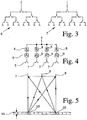
- die Beschaltung von Sendeantennen bzw. der Empfangsantennen gemäß einem bevorzugten Ausführungsbeispiel der Erfindung,
- Fig. 4
- die Beschaltung von Empfangsantennen gemäß einem anderen bevorzugten Ausführungsbeispiel der Erfindung,
- Fig. 5
- schematisch die Zusammensetzung des von einer Empfangsantenne empfangenen Signals gemäß einem nichterfindungsgemäßem Ausführungsbeispiel,
- Fig. 6
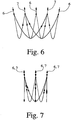
- die möglichen Kombinationen der Sendeantennen mit den Empfangsantennen gemäß einem bevorzugten Ausführungsbeispiel der Erfindung und
- Fig. 7
- die nichterfindungsgemäße Kombinationsmöglichkeiten, wenn die Antennen sowohl als Sende- als auch Empfangsantennen verwendet werden.
-
Fig. 1 zeigt schematisch ein Füllstandsmeßgerät zur Durchführung eines Füllstandsmeßverfahrens gemäß einem bevorzugten Ausführungsbeispiel der Erfindung. Oberhalb eines Behälters 1, in dem ein Medium 2, vorliegend nämlich ein Schüttgut, vorgesehen ist, ist eine Antenneneinrichtung 3 angeordnet, der von einer Signalerzeugungseinrichtung 4 ein Meßsignal zugeführt wird und die zur Weiterverarbeitung der erfaßten zurückreflektierten Anteile des Meßsignals mit einer Signalverarbeitungseinrichtung 5 verbunden ist. - Wie aus
Fig. 2 ersichtlich, weist die Antenneneinrichtung 3 gemäß einem bevorzugten Ausführungsbeispiel der Erfindung eine abwechselnde Anordnung von Sendeantennen 6 und Empfangsantennen 7 in einer Ebene auf. AusFig. 3 ist nun ersichtlich, wie die Sendeantennen 6 bzw. die Empfangsantennen 7 gemäß einem bevorzugten Ausführungsbeispiel verschaltet sein können, nämlich derart, daß jeweils genau eine Sendeantenne 6 sowie genau eine Empfangsantenne 7 "aktiviert" werden können. Das bedeutet, daß nacheinander alle Kombinationen einer jeweiligen Sendeantenne 6 mit einer jeweiligen Empfangsantenne 7 angeschaltet werden können, um anschließend das von der jeweiligen Empfangsantenne 7 empfangene Signal, nämlich den entsprechenden rückreflektierten Anteil des von der jeweiligen Sendeantenne 6 ausgesandten Meßsignals, in der Signalverarbeitungseinrichtung 5 weiterzuverarbeiten. - In der Signalverarbeitungseinrichtung 5 erfolgt dann die Ermittlung der jeweiligen Amplitude und Phase des zurückreflektierten Anteils des Meßsignals für eine jeweilige Kombination von Sendeantenne 6 und Empfangsantenne 7. Wie weiter oben schon angesprochen, werden die an den verschiedenen Empfangsstellen gewonnenen Amplituden- und Phaseninformationen im Rahmen eines geometrisch-mathematischen Modells für die Topologie der Oberflächenform des Mediums 2 verwendet werden, um Parameter für eine angenommene Oberflächenform zu ermitteln. Gegeben durch die Radar-Auflösung Δ x in Ausbreitungsrichtung einerseits und durch die "Ausleuchtung" bestimmter Bereiche ergeben sich im Rahmen des verwendeten Modells dann Auflösungszellen 10, wie z.B. in
Fig. 5 gezeigt, über die die Parametern für die Oberflächenstruktur des Mediums 2 in dem Behälter 1 ermittelt werden können. Näherungsweise erhält man damit also die gewünschten Informationen zur Topologie der Oberfläche des Mediums 2, so daß sich Aussagen über Größe, Form und Struktur des Schüttkegels des Mediums 2 treffen lassen. - Statt einer Überlagerung der von den einzelnen Empfangsantennen 7 empfangenen Signale in der Signalverarbeitungseinrichtung 5 kann, wie in
Fig. 4 gezeigt, auch eine analoge Überlagerung der empfangenen Signale erfolgen, nämlich indem den Empfangsantennen 7 direkt Phasenschalter 8 sowie Amplitudenschalter 9 nachgeschaltet sind. Diese ist jedoch verhältnismäßgi aufwendig, so daß eine "Software-Lösung" vorgezogen wird. - Jede Auflösungszelle 10, die über eine Kombination einer Sendeantenne 6 und einer Empfangsantenne 7 erfaßt wird, liefert quasi einen Ansatzpunkt, um über ein Näherungs- bzw. Interpolationsverfahren auf die Parameter zu schließen, über die bei einer angenommenen Form der Oberflächenstruktur des in dem Behälter 1 befindlichen Mediums 2 auf dessen konkret vorliegende Struktur zurückgeschlossen werden kann. Mit steigender Anzahl von Sendeantennen 6 und Empfangsantennen 7 steigt somit die Anzahl der Auflösungszellen 10, die quasi als Ausgangspunkt für die näherungsweise Ermittlung der Oberflächenstruktur des Mediums 2 dienen. Werden, wie in
Fig. 6 gezeigt, derartige Antennen verwendet, die entweder als Sendeantenne 6 oder als Empfangsantenne 7 wirken, so ergeben sich bei der Verwendung von n Sendeantennen 6 und m Empfangsantennen 7 eine Anzahl von n x m Auflösungszellen 10 zur Ermittlung der Oberflächenstruktur des Mediums 2. Ist es jedoch möglich, die Antennen sowohl als Sendeantennen 6 als auch als Empfangsantennen 7 zu verwenden, wie inFig. 7 dargestellt, läßt sich mit einer Gesamtzahl von n Sende-/Empfangsantennen 6, 7 eine Anzahl n + n (n-1)/2 Auflösungszellen 10 erzielen.
Claims (2)
- Verfahren zur Messung des Füllstands eines in einem Behälter (1) vorgesehenen Mediums (2) auf der Grundlage des Radar-Prinzips, wobei ein Meßsignal erzeugt und mittels einer Sendeantenne (6) in Richtung des Mediums (2) ausgesandt wird, ein zurückreflektierter Anteil des Meßsignals mittels einer Empfangsantenne (7) erfaßt wird und mittels der Laufzeit des Meßsignals ein Füllstand ermittelt wird, wobei das Meßsignal in eine Mehrzahl von voneinander verschiedenen Bereichen ausgesandt wird,
dadurch gekennzeichnet,
dass die zurückreflektierten Anteile des Meßsignals jeweils an einer Mehrzahl von voneinander verschiedenen Empfangsstellen empfangen werden, daß eine Mehrzahl von fest installierten Sendeantennen (6) und eine Mehrzahl von fest installierten Empfangsantennen (7) vorgesehen sind, wobei die Sendeantennen (6) und die Empfangsantennen (7) nicht als Sende- und Empfangsantennen wirken, wobei an jeder Empfangsstelle eine Empfangsantenne angeordnet ist,
wobei nacheinander jeweils eine Sendeantenne (6) und eine Empfangsantenne (7) gleichzeitig aktiviert werden, so daß mehrere, vorzugsweise alle Kombinationen einer Sendeantenne (6) mit einer Empfangsantenne (7) verwendet werden, und daß für wenigstens zwei Empfangsstellen die jeweilige Amplitude und Phase des zurückreflektierten Anteils des Meßsignals ermittelt werden und mit diesen Amplituden- und Phaseninformationen auf der Grundlage eines geometrischen Modells für die Oberflächenform des in dem Behälter (1) vorgesehenen Mediums (2) die Oberflächenstruktur des Mediums (2) näherungsweise bestimmt wird. - Verfahren nach Anspruch 1, dadurch gekennzeichnet, daß als Meßsignal ein FMCW-Signal verwendet wird.
Applications Claiming Priority (1)
| Application Number | Priority Date | Filing Date | Title |
|---|---|---|---|
| DE102005011686.8A DE102005011686B4 (de) | 2005-03-11 | 2005-03-11 | Verfahren zur Messung des Füllstands eines in einem Behälter vorgesehenen Mediums auf der Grundlage des Radar-Prinzips |
Publications (3)
| Publication Number | Publication Date |
|---|---|
| EP1701142A2 EP1701142A2 (de) | 2006-09-13 |
| EP1701142A3 EP1701142A3 (de) | 2006-11-15 |
| EP1701142B1 true EP1701142B1 (de) | 2018-10-10 |
Family
ID=36579607
Family Applications (1)
| Application Number | Title | Priority Date | Filing Date |
|---|---|---|---|
| EP05013247.1A Expired - Lifetime EP1701142B1 (de) | 2005-03-11 | 2005-06-20 | Verfahren zur Messung des Füllstands eines in einem Behälter vorgesehenen Mediums auf der Grundlage des Radar-Prinzips |
Country Status (3)
| Country | Link |
|---|---|
| US (1) | US7408501B2 (de) |
| EP (1) | EP1701142B1 (de) |
| DE (1) | DE102005011686B4 (de) |
Families Citing this family (36)
| Publication number | Priority date | Publication date | Assignee | Title |
|---|---|---|---|---|
| DE102005011686B4 (de) * | 2005-03-11 | 2020-02-27 | Krohne S.A. | Verfahren zur Messung des Füllstands eines in einem Behälter vorgesehenen Mediums auf der Grundlage des Radar-Prinzips |
| FR2907546B1 (fr) * | 2006-10-19 | 2009-01-23 | Crealyst Sarl | Systeme de determination du relief d'une surface de remplissage de granules dans un reacteur petrochimique |
| DE102007042042B4 (de) * | 2007-09-05 | 2020-03-26 | Endress+Hauser SE+Co. KG | Verfahren zur Ermittlung und Überwachung des Füllstands eines Mediums in einem Behälter nach einem Laufzeitmessverfahren |
| EP2128576B1 (de) | 2008-05-27 | 2016-12-28 | VEGA Grieshaber KG | Auswertung der Echoform bei Füllstandsensoren |
| DE102008050329A1 (de) | 2008-10-10 | 2010-04-15 | Endress + Hauser Gmbh + Co. Kg | Mit Mikrowellen arbeitendes Füllstandsmessgerät |
| AT508369B1 (de) | 2009-06-17 | 2011-01-15 | Vatron Gmbh | Verfahren und vorrichtung zur berechnung einer oberfläche eines füllguts eines behälters |
| DE102010014457A1 (de) | 2010-04-09 | 2011-10-13 | Gottfried Wilhelm Leibniz Universität Hannover | Verfahren zur Bestimmung mindestens einer Eigenschaft eines Mediums in einem Behälter und Messeinrichtung hierzu |
| US8380401B2 (en) | 2010-06-09 | 2013-02-19 | Cnh America Llc | Automatic grain transfer control system based on real time modeling of a fill level profile for regions of the receiving container |
| DE102010031276A1 (de) * | 2010-07-13 | 2012-01-19 | Endress + Hauser Gmbh + Co. Kg | Füllstandsmessgerät zur Ermittlung und Überwachung eines Füllstandes eines im Prozessraum eines Behälters befindlichen Mediums mittels einem Mikrowellen-Laufzeitmessverfahren |
| DE102010062108A1 (de) * | 2010-11-29 | 2012-05-31 | Robert Bosch Gmbh | Verfahren und Vorrichtung zur Bestimmung der Neigung einer Oberfläche einer Flüssigkeit oder eines granularen Materials |
| DE102012003398B4 (de) | 2012-02-23 | 2015-06-25 | Krohne Messtechnik Gmbh | Nach dem Radar-Prinzip arbeitendes Füllstandsmessgerät |
| DE102012104090A1 (de) * | 2012-05-10 | 2013-11-14 | Endress + Hauser Gmbh + Co. Kg | Stapelbare Hornantennenelemente für Antennenanordnungen |
| DE102012106938A1 (de) * | 2012-07-30 | 2014-01-30 | Endress + Hauser Gmbh + Co. Kg | Abbildende Erfassung eines Radargesichtsfelds in der Prozessautomatisierungstechnik |
| EP2837950B1 (de) * | 2013-08-14 | 2016-05-04 | VEGA Grieshaber KG | Radar-Strahlablenkungseinheit für ein Füllstandradar |
| WO2015120883A1 (de) * | 2014-02-11 | 2015-08-20 | Vega Grieshaber Kg | Topologiebestimmung einer füllgutoberfläche |
| DE102014111987A1 (de) * | 2014-08-21 | 2016-02-25 | Endress + Hauser Gmbh + Co. Kg | Vorrichtung zur Bestimmung eines Füllstands eines Schüttguts |
| EP3209979B1 (de) * | 2014-10-22 | 2023-12-06 | VEGA Grieshaber KG | Topologiebestimmung einer füllgutoberfläche mit gleichmässiger zeilenabtastung |
| DE102015100414A1 (de) | 2015-01-13 | 2016-07-14 | Krohne Messtechnik Gmbh | Vorrichtung zur Bestimmung des Füllstands eines Mediums in einem Behälter |
| DE102015100415A1 (de) | 2015-01-13 | 2016-07-14 | Krohne Messtechnik Gmbh | Vorrichtung zur Bestimmung des Füllstands eines Mediums |
| DE102015100417A1 (de) | 2015-01-13 | 2016-07-14 | Krohne Messtechnik Gmbh | Verfahren zur Bestimmung des Füllstands eines Mediums in einem Behälter |
| EP3115779B1 (de) * | 2015-07-06 | 2023-07-26 | ABB Schweiz AG | System und verfahren zur messung einer signalausbreitungsgeschwindigkeit in einem flüssigen oder gasförmigen medium |
| DE102015219276A1 (de) | 2015-10-06 | 2017-04-06 | Vega Grieshaber Kg | 3D-Messung mit Master-Slave-Konzept |
| WO2017084700A1 (de) * | 2015-11-17 | 2017-05-26 | Vega Grieshaber Kg | Antennenvorrichtung und verfahren zum senden und/oder empfangen eines signals |
| US10228274B2 (en) * | 2016-09-13 | 2019-03-12 | Finetek Co., Ltd. | Liquid level sensing apparatus for long-distance automatically enhancing signal-to-noise ratio |
| US10775211B2 (en) | 2017-05-03 | 2020-09-15 | Quest Automated Services, LLC | Real-time vessel monitoring system |
| CN108981832B (zh) * | 2018-07-27 | 2020-04-21 | 南方科技大学 | 一种废水流量测量电路及装置 |
| AT523436B1 (de) * | 2020-05-20 | 2021-08-15 | Rosenberger Telematics Gmbh | Verfahren zum Bestimmen der Schüttgutmenge in einem stehenden Behälter |
| DE102020129764B4 (de) * | 2020-11-11 | 2026-05-13 | Endress+Hauser SE+Co. KG | Hinsichtlich seiner Taktung kompensierbares Füllstandsmessgerät und entsprechendes Kompensationsverfahren |
| DE202022102029U1 (de) | 2022-04-14 | 2022-05-03 | Starrag Gmbh | Vorrichtung zur Erfassung der Position eines Auffangbehälters |
| DE102022128063A1 (de) * | 2022-10-24 | 2024-04-25 | Endress+Hauser SE+Co. KG | Übertragung ortsaufgelöster Füllstandsmesswerte |
| DE102022128393A1 (de) * | 2022-10-26 | 2024-05-02 | Endress+Hauser SE+Co. KG | Ortsauflösende Füllstandsmessung |
| US12228525B1 (en) * | 2024-01-27 | 2025-02-18 | Barrel Proof Technologies Llc | System and method for determining alcohol content utilizing container monitoring system |
| US12609185B2 (en) | 2024-01-27 | 2026-04-21 | Barrel Proof Technologies Llc | Artificial intelligence driven monitoring system for aging whiskey |
| US12117329B1 (en) * | 2024-01-27 | 2024-10-15 | Barrel Proof Technologies Llc | Container monitoring system and method thereof |
| US12422295B2 (en) * | 2024-01-27 | 2025-09-23 | Barrel Proof Technologies Llc | System and method for determining content utilizing externally mounted container monitoring system |
| US12228445B1 (en) | 2024-01-27 | 2025-02-18 | Barrel Proof Technologies Llc | System and method for determining alcohol content within container utilizing container monitoring system |
Citations (1)
| Publication number | Priority date | Publication date | Assignee | Title |
|---|---|---|---|---|
| US5115242A (en) * | 1990-03-30 | 1992-05-19 | Nkk Corporation | In-furnace slag level measuring apparatus |
Family Cites Families (32)
| Publication number | Priority date | Publication date | Assignee | Title |
|---|---|---|---|---|
| GB9211086D0 (en) * | 1992-05-23 | 1992-07-15 | Cambridge Consultants | Short range electromagnetic sensing signal processing |
| DE4233324C2 (de) * | 1992-10-05 | 1996-02-01 | Krohne Messtechnik Kg | Verfahren zur Messung des Füllstandes einer Flüssigkeit in einem Behälter nach dem Radarprinzip |
| US5337289A (en) * | 1993-07-16 | 1994-08-09 | The United States Of America As Represented By The Department Of Energy | Phased-array ultrasonic surface contour mapping system and method for solids hoppers and the like |
| DE4339441A1 (de) * | 1993-11-19 | 1995-05-24 | Incatronic Phoenix Mestechnik | Verfahren zur Messung des Füllgrads von mit Füllgut gefüllten Behältern |
| US6892572B2 (en) * | 1994-05-09 | 2005-05-17 | Automotive Technologies International, Inc. | Method and apparatus for measuring the quantity of a liquid in a vehicle container |
| US5614831A (en) * | 1995-02-13 | 1997-03-25 | Saab Marine Electronics Ab | Method and apparatus for level gauging using radar in floating roof tanks |
| EP0770859A1 (de) * | 1995-10-27 | 1997-05-02 | Endress + Hauser Gmbh + Co. | Verfahren zum Abgleich bei der Füllstandsmessung |
| EP0887658B1 (de) * | 1997-06-27 | 2004-08-25 | EADS Deutschland GmbH | Füllstandmessradargerät |
| JP3525426B2 (ja) * | 1997-11-28 | 2004-05-10 | トヨタ自動車株式会社 | レーダ装置 |
| DE19801511C2 (de) * | 1998-01-16 | 2001-12-06 | Wieland Werke Ag | Verfahren zur Konturerfassung mittels Mikrowellen und Vorrichtung zur Durchführung des Verfahrens |
| US5942687A (en) * | 1998-04-01 | 1999-08-24 | The United States Of America As Represented By The Secretary Of The Navy | Method and apparatus for in situ measurement of corrosion in filled tanks |
| US6082419A (en) * | 1998-04-01 | 2000-07-04 | Electro-Pro, Inc. | Control method and apparatus to detect the presence of a first object and monitor a relative position of the first or subsequent objects such as container identification and product fill control |
| US6310574B1 (en) * | 1999-08-05 | 2001-10-30 | Vega Grieshaber Kg | Level transmitter |
| WO2001060718A2 (en) * | 2000-02-17 | 2001-08-23 | Bintech. Lllp | Bulk materials management apparatus and method |
| DE10009406C2 (de) * | 2000-02-28 | 2002-01-10 | Sasib Beverage Deutschland Gmb | Verfahren und Vorrichtung zur berührungslosen Füllstandsmessung |
| EP1156302B1 (de) * | 2000-05-15 | 2004-09-29 | Krohne Messtechnik Gmbh & Co. Kg | Füllstandsmessgerät |
| DE20012378U1 (de) * | 2000-07-17 | 2000-10-19 | Leica Microsystems Heidelberg Gmbh, 68165 Mannheim | Anordnung zur spektral empfindlichen Auf- und Durchlichtbeleuchtung |
| US6672155B2 (en) * | 2000-10-14 | 2004-01-06 | Endress + Hauser Gmbh + Co. | Apparatus for determining the filling level of a filling material in a container |
| US6634234B1 (en) * | 2001-02-10 | 2003-10-21 | Vega Grieshaber Kg | Adjustable measurement head and a level measurement device and method employing it |
| DE10139242A1 (de) * | 2001-08-09 | 2003-03-06 | Grieshaber Vega Kg | Verfahren und Vorrichtung zum Erfassen eines Befüllvorgangs |
| DE10149851A1 (de) * | 2001-10-10 | 2003-04-24 | Endress & Hauser Gmbh & Co Kg | Vorrichtung zur Bestimmung des Füllstandes eines Füllguts in einem Behälter |
| US7339484B2 (en) * | 2002-06-27 | 2008-03-04 | Hewlett-Packard Development Company, L.P. | Event-driven discovery method and apparatus |
| DE10260959A1 (de) * | 2002-12-20 | 2004-07-15 | Endress + Hauser Gmbh + Co. Kg | Füllstandsmeßgerät und Verfahren zur Füllstandsmessung |
| US6759977B1 (en) * | 2002-12-20 | 2004-07-06 | Saab Marine Electronics Ab | Method and apparatus for radar-based level gauging |
| US6795015B2 (en) * | 2003-01-29 | 2004-09-21 | Saab Rosemount Tank Radar Ab | Bottom reflector for a radar-based level gauge |
| US6995706B2 (en) * | 2004-02-13 | 2006-02-07 | Saab Rosemount Tank Radar Ab | Method and an arrangement in a radar level gauging system |
| WO2005078475A1 (en) * | 2004-02-13 | 2005-08-25 | Saab Rosemount Tank Radar Ab | A method and an arrangement in a radar level gauging system |
| US7319401B2 (en) * | 2004-08-27 | 2008-01-15 | Rosemount Tank Radar Ab | Radar level gauge system with variable alarm limits |
| DE102005011686B4 (de) * | 2005-03-11 | 2020-02-27 | Krohne S.A. | Verfahren zur Messung des Füllstands eines in einem Behälter vorgesehenen Mediums auf der Grundlage des Radar-Prinzips |
| US20070012113A1 (en) * | 2005-07-18 | 2007-01-18 | Helicos Biosciences Corporation | Non-contact detection |
| US7458260B2 (en) * | 2005-11-07 | 2008-12-02 | Claridy Solutions, Inc. | Fluid level detection using RF |
| US7363812B2 (en) * | 2005-11-09 | 2008-04-29 | Rosemount Tank Radar Ab | Radar level gauge with variable transmission power |
-
2005
- 2005-03-11 DE DE102005011686.8A patent/DE102005011686B4/de not_active Expired - Fee Related
- 2005-06-20 EP EP05013247.1A patent/EP1701142B1/de not_active Expired - Lifetime
- 2005-08-02 US US11/194,947 patent/US7408501B2/en active Active
Patent Citations (1)
| Publication number | Priority date | Publication date | Assignee | Title |
|---|---|---|---|---|
| US5115242A (en) * | 1990-03-30 | 1992-05-19 | Nkk Corporation | In-furnace slag level measuring apparatus |
Also Published As
| Publication number | Publication date |
|---|---|
| DE102005011686A1 (de) | 2006-09-14 |
| US20060201246A1 (en) | 2006-09-14 |
| EP1701142A3 (de) | 2006-11-15 |
| EP1701142A2 (de) | 2006-09-13 |
| DE102005011686B4 (de) | 2020-02-27 |
| US7408501B2 (en) | 2008-08-05 |
Similar Documents
| Publication | Publication Date | Title |
|---|---|---|
| DE102005011686B4 (de) | Verfahren zur Messung des Füllstands eines in einem Behälter vorgesehenen Mediums auf der Grundlage des Radar-Prinzips | |
| EP2128576B1 (de) | Auswertung der Echoform bei Füllstandsensoren | |
| EP0668488B1 (de) | Anordnung zur Messung des Füllstands in einem Behälter | |
| DE102007060579B4 (de) | Verfahren zur Ermittlung und/oder zur Beurteilung des Befüllzustands eines mit zumindest einem Medium gefüllten Behälters | |
| EP3105554B1 (de) | Topologiebestimmung einer füllgutoberfläche | |
| EP1972905B1 (de) | Füllstandsmessvorrichtung | |
| EP3076186A1 (de) | Bestimmung von pegel und fliessgeschwindigkeit eines mediums | |
| DE10049995A1 (de) | Füllstandsmessgerät | |
| DE102013213340A1 (de) | Bestimmung einer Distanz und einer Fließgeschwindigkeit eines Mediums | |
| EP3861305B1 (de) | Verfahren zur füllstandsmessung | |
| WO2016062341A1 (de) | Topologiebestimmung einer füllgutoberfläche mit gleichmässiger zeilenabtastung | |
| WO2019170648A1 (de) | Verfahren zur ermittlung zumindest eines physikalischen parameters eines systems unter ausnutzung der reflexion von einem referenzobjekt | |
| EP2687830A2 (de) | Verfahren zur Zustandsüberwachung eines nach dem Radar-Prinzip arbeitenden Füllstandmessgeräts und entsprechendes Füllstandmessgerät | |
| EP3918313B1 (de) | Messgerät zur bestimmung eines dielektrizitätswertes | |
| EP3746753B1 (de) | Verfahren zur detektion von potentiellen fehlerzuständen an einem fmcw-basierten füllstandsmessgerät | |
| DE102005063079B4 (de) | Verfahren zur Ermittlung und Überwachung des Füllstands eines Mediums in einem Behälter | |
| DE102017100269A1 (de) | Verfahren zur Detektion eines Fehlerzustandes an einem FMCW-basierten Füllstandsmessgerät | |
| WO2001046653A1 (de) | Verfahren und vorrichtung zur bestimmung des füllstands eines füllguts in einem behälter | |
| DE102021115874A1 (de) | Füllstandsmessung | |
| EP1004858A1 (de) | Füllstandsmessgerät | |
| DE102005011778A1 (de) | Verfahren zur Messung des Füllstands eines in einem Behälter vorgesehenen Mediums auf der Grundlage des Radar-Prinzips | |
| DE10063694A1 (de) | Verfahren und Vorrichtung zum Messen von Lage und Form von Ablagen eines Backofens | |
| EP3857182B1 (de) | Füllstandsmessgerät | |
| EP2789996B1 (de) | Echokurvenbestimmung mit bereichsweise unterschiedlicher auflösung | |
| DE102019124825A1 (de) | Messgerät zur Bestimmung eines Dielelektrizitätswertes |
Legal Events
| Date | Code | Title | Description |
|---|---|---|---|
| PUAI | Public reference made under article 153(3) epc to a published international application that has entered the european phase |
Free format text: ORIGINAL CODE: 0009012 |
|
| AK | Designated contracting states |
Kind code of ref document: A2 Designated state(s): AT BE BG CH CY CZ DE DK EE ES FI FR GB GR HU IE IS IT LI LT LU MC NL PL PT RO SE SI SK TR |
|
| AX | Request for extension of the european patent |
Extension state: AL BA HR LV MK YU |
|
| PUAL | Search report despatched |
Free format text: ORIGINAL CODE: 0009013 |
|
| AK | Designated contracting states |
Kind code of ref document: A3 Designated state(s): AT BE BG CH CY CZ DE DK EE ES FI FR GB GR HU IE IS IT LI LT LU MC NL PL PT RO SE SI SK TR |
|
| AX | Request for extension of the european patent |
Extension state: AL BA HR LV MK YU |
|
| RIC1 | Information provided on ipc code assigned before grant |
Ipc: G01F 23/284 20060101AFI20060622BHEP Ipc: G01B 15/04 20060101ALI20061012BHEP |
|
| 17P | Request for examination filed |
Effective date: 20061218 |
|
| 17Q | First examination report despatched |
Effective date: 20070115 |
|
| AKX | Designation fees paid |
Designated state(s): AT BE BG CH CY CZ DE DK EE ES FI FR GB GR HU IE IS IT LI LT LU MC NL PL PT RO SE SI SK TR |
|
| APBK | Appeal reference recorded |
Free format text: ORIGINAL CODE: EPIDOSNREFNE |
|
| APBN | Date of receipt of notice of appeal recorded |
Free format text: ORIGINAL CODE: EPIDOSNNOA2E |
|
| APBR | Date of receipt of statement of grounds of appeal recorded |
Free format text: ORIGINAL CODE: EPIDOSNNOA3E |
|
| APAF | Appeal reference modified |
Free format text: ORIGINAL CODE: EPIDOSCREFNE |
|
| APBT | Appeal procedure closed |
Free format text: ORIGINAL CODE: EPIDOSNNOA9E |
|
| GRAP | Despatch of communication of intention to grant a patent |
Free format text: ORIGINAL CODE: EPIDOSNIGR1 |
|
| STAA | Information on the status of an ep patent application or granted ep patent |
Free format text: STATUS: GRANT OF PATENT IS INTENDED |
|
| GRAS | Grant fee paid |
Free format text: ORIGINAL CODE: EPIDOSNIGR3 |
|
| INTG | Intention to grant announced |
Effective date: 20180629 |
|
| GRAA | (expected) grant |
Free format text: ORIGINAL CODE: 0009210 |
|
| STAA | Information on the status of an ep patent application or granted ep patent |
Free format text: STATUS: THE PATENT HAS BEEN GRANTED |
|
| AK | Designated contracting states |
Kind code of ref document: B1 Designated state(s): AT BE BG CH CY CZ DE DK EE ES FI FR GB GR HU IE IS IT LI LT LU MC NL PL PT RO SE SI SK TR |
|
| REG | Reference to a national code |
Ref country code: GB Ref legal event code: FG4D Free format text: NOT ENGLISH |
|
| REG | Reference to a national code |
Ref country code: CH Ref legal event code: EP Ref country code: AT Ref legal event code: REF Ref document number: 1051780 Country of ref document: AT Kind code of ref document: T Effective date: 20181015 |
|
| REG | Reference to a national code |
Ref country code: IE Ref legal event code: FG4D Free format text: LANGUAGE OF EP DOCUMENT: GERMAN |
|
| REG | Reference to a national code |
Ref country code: DE Ref legal event code: R096 Ref document number: 502005015929 Country of ref document: DE |
|
| REG | Reference to a national code |
Ref country code: NL Ref legal event code: MP Effective date: 20181010 |
|
| REG | Reference to a national code |
Ref country code: LT Ref legal event code: MG4D |
|
| PG25 | Lapsed in a contracting state [announced via postgrant information from national office to epo] |
Ref country code: NL Free format text: LAPSE BECAUSE OF FAILURE TO SUBMIT A TRANSLATION OF THE DESCRIPTION OR TO PAY THE FEE WITHIN THE PRESCRIBED TIME-LIMIT Effective date: 20181010 |
|
| PG25 | Lapsed in a contracting state [announced via postgrant information from national office to epo] |
Ref country code: PL Free format text: LAPSE BECAUSE OF FAILURE TO SUBMIT A TRANSLATION OF THE DESCRIPTION OR TO PAY THE FEE WITHIN THE PRESCRIBED TIME-LIMIT Effective date: 20181010 Ref country code: LT Free format text: LAPSE BECAUSE OF FAILURE TO SUBMIT A TRANSLATION OF THE DESCRIPTION OR TO PAY THE FEE WITHIN THE PRESCRIBED TIME-LIMIT Effective date: 20181010 Ref country code: ES Free format text: LAPSE BECAUSE OF FAILURE TO SUBMIT A TRANSLATION OF THE DESCRIPTION OR TO PAY THE FEE WITHIN THE PRESCRIBED TIME-LIMIT Effective date: 20181010 Ref country code: BG Free format text: LAPSE BECAUSE OF FAILURE TO SUBMIT A TRANSLATION OF THE DESCRIPTION OR TO PAY THE FEE WITHIN THE PRESCRIBED TIME-LIMIT Effective date: 20190110 Ref country code: FI Free format text: LAPSE BECAUSE OF FAILURE TO SUBMIT A TRANSLATION OF THE DESCRIPTION OR TO PAY THE FEE WITHIN THE PRESCRIBED TIME-LIMIT Effective date: 20181010 Ref country code: IS Free format text: LAPSE BECAUSE OF FAILURE TO SUBMIT A TRANSLATION OF THE DESCRIPTION OR TO PAY THE FEE WITHIN THE PRESCRIBED TIME-LIMIT Effective date: 20190210 |
|
| PG25 | Lapsed in a contracting state [announced via postgrant information from national office to epo] |
Ref country code: GR Free format text: LAPSE BECAUSE OF FAILURE TO SUBMIT A TRANSLATION OF THE DESCRIPTION OR TO PAY THE FEE WITHIN THE PRESCRIBED TIME-LIMIT Effective date: 20190111 Ref country code: PT Free format text: LAPSE BECAUSE OF FAILURE TO SUBMIT A TRANSLATION OF THE DESCRIPTION OR TO PAY THE FEE WITHIN THE PRESCRIBED TIME-LIMIT Effective date: 20190210 Ref country code: SE Free format text: LAPSE BECAUSE OF FAILURE TO SUBMIT A TRANSLATION OF THE DESCRIPTION OR TO PAY THE FEE WITHIN THE PRESCRIBED TIME-LIMIT Effective date: 20181010 |
|
| REG | Reference to a national code |
Ref country code: DE Ref legal event code: R097 Ref document number: 502005015929 Country of ref document: DE |
|
| PG25 | Lapsed in a contracting state [announced via postgrant information from national office to epo] |
Ref country code: DK Free format text: LAPSE BECAUSE OF FAILURE TO SUBMIT A TRANSLATION OF THE DESCRIPTION OR TO PAY THE FEE WITHIN THE PRESCRIBED TIME-LIMIT Effective date: 20181010 Ref country code: CZ Free format text: LAPSE BECAUSE OF FAILURE TO SUBMIT A TRANSLATION OF THE DESCRIPTION OR TO PAY THE FEE WITHIN THE PRESCRIBED TIME-LIMIT Effective date: 20181010 Ref country code: IT Free format text: LAPSE BECAUSE OF FAILURE TO SUBMIT A TRANSLATION OF THE DESCRIPTION OR TO PAY THE FEE WITHIN THE PRESCRIBED TIME-LIMIT Effective date: 20181010 |
|
| PLBE | No opposition filed within time limit |
Free format text: ORIGINAL CODE: 0009261 |
|
| STAA | Information on the status of an ep patent application or granted ep patent |
Free format text: STATUS: NO OPPOSITION FILED WITHIN TIME LIMIT |
|
| PG25 | Lapsed in a contracting state [announced via postgrant information from national office to epo] |
Ref country code: SK Free format text: LAPSE BECAUSE OF FAILURE TO SUBMIT A TRANSLATION OF THE DESCRIPTION OR TO PAY THE FEE WITHIN THE PRESCRIBED TIME-LIMIT Effective date: 20181010 Ref country code: EE Free format text: LAPSE BECAUSE OF FAILURE TO SUBMIT A TRANSLATION OF THE DESCRIPTION OR TO PAY THE FEE WITHIN THE PRESCRIBED TIME-LIMIT Effective date: 20181010 Ref country code: RO Free format text: LAPSE BECAUSE OF FAILURE TO SUBMIT A TRANSLATION OF THE DESCRIPTION OR TO PAY THE FEE WITHIN THE PRESCRIBED TIME-LIMIT Effective date: 20181010 |
|
| 26N | No opposition filed |
Effective date: 20190711 |
|
| PG25 | Lapsed in a contracting state [announced via postgrant information from national office to epo] |
Ref country code: SI Free format text: LAPSE BECAUSE OF FAILURE TO SUBMIT A TRANSLATION OF THE DESCRIPTION OR TO PAY THE FEE WITHIN THE PRESCRIBED TIME-LIMIT Effective date: 20181010 |
|
| PG25 | Lapsed in a contracting state [announced via postgrant information from national office to epo] |
Ref country code: MC Free format text: LAPSE BECAUSE OF FAILURE TO SUBMIT A TRANSLATION OF THE DESCRIPTION OR TO PAY THE FEE WITHIN THE PRESCRIBED TIME-LIMIT Effective date: 20181010 |
|
| GBPC | Gb: european patent ceased through non-payment of renewal fee |
Effective date: 20190620 |
|
| REG | Reference to a national code |
Ref country code: BE Ref legal event code: MM Effective date: 20190630 |
|
| PG25 | Lapsed in a contracting state [announced via postgrant information from national office to epo] |
Ref country code: TR Free format text: LAPSE BECAUSE OF FAILURE TO SUBMIT A TRANSLATION OF THE DESCRIPTION OR TO PAY THE FEE WITHIN THE PRESCRIBED TIME-LIMIT Effective date: 20181010 |
|
| PG25 | Lapsed in a contracting state [announced via postgrant information from national office to epo] |
Ref country code: IE Free format text: LAPSE BECAUSE OF NON-PAYMENT OF DUE FEES Effective date: 20190620 Ref country code: GB Free format text: LAPSE BECAUSE OF NON-PAYMENT OF DUE FEES Effective date: 20190620 |
|
| PG25 | Lapsed in a contracting state [announced via postgrant information from national office to epo] |
Ref country code: BE Free format text: LAPSE BECAUSE OF NON-PAYMENT OF DUE FEES Effective date: 20190630 Ref country code: LU Free format text: LAPSE BECAUSE OF NON-PAYMENT OF DUE FEES Effective date: 20190620 |
|
| PGFP | Annual fee paid to national office [announced via postgrant information from national office to epo] |
Ref country code: FR Payment date: 20200619 Year of fee payment: 16 Ref country code: CH Payment date: 20200618 Year of fee payment: 16 |
|
| REG | Reference to a national code |
Ref country code: AT Ref legal event code: MM01 Ref document number: 1051780 Country of ref document: AT Kind code of ref document: T Effective date: 20190620 |
|
| PGFP | Annual fee paid to national office [announced via postgrant information from national office to epo] |
Ref country code: DE Payment date: 20200826 Year of fee payment: 16 |
|
| PG25 | Lapsed in a contracting state [announced via postgrant information from national office to epo] |
Ref country code: AT Free format text: LAPSE BECAUSE OF NON-PAYMENT OF DUE FEES Effective date: 20190620 |
|
| PG25 | Lapsed in a contracting state [announced via postgrant information from national office to epo] |
Ref country code: CY Free format text: LAPSE BECAUSE OF FAILURE TO SUBMIT A TRANSLATION OF THE DESCRIPTION OR TO PAY THE FEE WITHIN THE PRESCRIBED TIME-LIMIT Effective date: 20181010 |
|
| PG25 | Lapsed in a contracting state [announced via postgrant information from national office to epo] |
Ref country code: HU Free format text: LAPSE BECAUSE OF FAILURE TO SUBMIT A TRANSLATION OF THE DESCRIPTION OR TO PAY THE FEE WITHIN THE PRESCRIBED TIME-LIMIT; INVALID AB INITIO Effective date: 20050620 |
|
| REG | Reference to a national code |
Ref country code: DE Ref legal event code: R119 Ref document number: 502005015929 Country of ref document: DE |
|
| REG | Reference to a national code |
Ref country code: CH Ref legal event code: PL |
|
| PG25 | Lapsed in a contracting state [announced via postgrant information from national office to epo] |
Ref country code: LI Free format text: LAPSE BECAUSE OF NON-PAYMENT OF DUE FEES Effective date: 20210630 Ref country code: DE Free format text: LAPSE BECAUSE OF NON-PAYMENT OF DUE FEES Effective date: 20220101 Ref country code: CH Free format text: LAPSE BECAUSE OF NON-PAYMENT OF DUE FEES Effective date: 20210630 |
|
| PG25 | Lapsed in a contracting state [announced via postgrant information from national office to epo] |
Ref country code: FR Free format text: LAPSE BECAUSE OF NON-PAYMENT OF DUE FEES Effective date: 20210630 |