EP1700655A1 - Mécanisme de support d'outil de coupe et broche - Google Patents
Mécanisme de support d'outil de coupe et broche Download PDFInfo
- Publication number
- EP1700655A1 EP1700655A1 EP06004267A EP06004267A EP1700655A1 EP 1700655 A1 EP1700655 A1 EP 1700655A1 EP 06004267 A EP06004267 A EP 06004267A EP 06004267 A EP06004267 A EP 06004267A EP 1700655 A1 EP1700655 A1 EP 1700655A1
- Authority
- EP
- European Patent Office
- Prior art keywords
- cutting tool
- main shaft
- annular elastic
- elastic member
- spindle unit
- Prior art date
- Legal status (The legal status is an assumption and is not a legal conclusion. Google has not performed a legal analysis and makes no representation as to the accuracy of the status listed.)
- Withdrawn
Links
Images


Classifications
-
- B—PERFORMING OPERATIONS; TRANSPORTING
- B23—MACHINE TOOLS; METAL-WORKING NOT OTHERWISE PROVIDED FOR
- B23B—TURNING; BORING
- B23B31/00—Chucks; Expansion mandrels; Adaptations thereof for remote control
- B23B31/02—Chucks
- B23B31/10—Chucks characterised by the retaining or gripping devices or their immediate operating means
- B23B31/117—Retention by friction only, e.g. using springs, resilient sleeves, tapers
- B23B31/1175—Retention by friction only, e.g. using springs, resilient sleeves, tapers using elastomer rings or sleeves
-
- B—PERFORMING OPERATIONS; TRANSPORTING
- B23—MACHINE TOOLS; METAL-WORKING NOT OTHERWISE PROVIDED FOR
- B23B—TURNING; BORING
- B23B31/00—Chucks; Expansion mandrels; Adaptations thereof for remote control
- B23B31/005—Cylindrical shanks of tools
-
- B—PERFORMING OPERATIONS; TRANSPORTING
- B23—MACHINE TOOLS; METAL-WORKING NOT OTHERWISE PROVIDED FOR
- B23B—TURNING; BORING
- B23B31/00—Chucks; Expansion mandrels; Adaptations thereof for remote control
- B23B31/008—Chucks; Expansion mandrels; Adaptations thereof for remote control with arrangements for transmitting torque
-
- B—PERFORMING OPERATIONS; TRANSPORTING
- B23—MACHINE TOOLS; METAL-WORKING NOT OTHERWISE PROVIDED FOR
- B23B—TURNING; BORING
- B23B2231/00—Details of chucks, toolholder shanks or tool shanks
- B23B2231/02—Features of shanks of tools not relating to the operation performed by the tool
- B23B2231/0216—Overall cross sectional shape of the shank
- B23B2231/0244—Special forms not otherwise provided for
-
- B—PERFORMING OPERATIONS; TRANSPORTING
- B23—MACHINE TOOLS; METAL-WORKING NOT OTHERWISE PROVIDED FOR
- B23B—TURNING; BORING
- B23B2231/00—Details of chucks, toolholder shanks or tool shanks
- B23B2231/02—Features of shanks of tools not relating to the operation performed by the tool
- B23B2231/026—Grooves
- B23B2231/0268—Radial grooves
Definitions
- the present invention relates to a cutting tool holding mechanism and a spindle unit, in particular, to a cutting tool holding mechanism and a spindle unit that are applicable to dental instruments, surgical instruments, machine tools, or the like.
- a spindle unit is incorporated and used in various machinery, such as a dental handpiece, a surgical handpiece, and a machine tool.
- An example of a conventional spindle unit is shown in Fig. 7.
- Spindle unit 50 includes holder 51 having threads 51a formed on the front end portion thereof and hollow 51b, collet chuck 52 having front and rear tapered surfaces 52a and 52b, and nut 53 to be screwed onto the threads 51a of the holder 51.
- a tapered surface is formed that is complementary to the front tapered surface 52a of the collet chuck 52.
- a tapered surface is formed that is complementary to the rear tapered surface 52b of the collet chuck 52.
- Cutting tool 54 is held in the holder 51 by inserting the collet chuck 52 into the hollow 51b of the holder 51, inserting the rear end of the cutting tool 54 into the collet chuck 52, and screwing the nut 53 onto the threads 51a on the front end portion of the holder 51, to press the collet chuck 52 against the cutting tool 54 by means of the holder 51 and the nut 53.
- Such a conventional cutting tool holding mechanism has various drawbacks.
- the tapered surfaces on the holder and the nut are hard to be formed with precision. Tapered surfaces with insufficient precision may result in insufficient contact with the tapered surfaces of the collet chuck, which may disadvantageously cause shaking, vibration, and wear of the spindle.
- the collet chuck, the holder, and the nut are usually made of metal, thus gaps tend to be formed between these parts, which allow intrusion of debris.
- the collet chuck is constrained on its conical surface, so that it tends to slip in the circumferential direction thereof, and cannot hold the cutting tool securely without strong compression by the holder and the nut. Further, upon attachment of the cutting tool, alignment must be adjusted, which adds to the complexity in its attachment/detachment.
- the present invention is made in the light of the drawbacks in the prior art. It is therefore an object of the present invention to provide a cutting tool holding mechanism and a spindle unit, wherein the precision of the component parts may be satisfied relatively easily, a gap is hard to form between the parts, and the cutting tool is easily attached and detached.
- a cutting tool holding mechanism for a spindle unit said spindle unit having a cylindrical main shaft for receiving a cutting tool therein, said main shaft rotatably supported in a housing by means of a bearing, said mechanism comprising:
- the cutting tool includes dental treatment tools, surgical treatment tools, tools for machine tools, and the like, and the cutting tool holding mechanism and the spindle unit may be applied to dental apparatuses, surgical apparatuses, machine tools, or the like.
- the engaging sections for preventing relative circumferential movement of the cutting tool in the main shaft may be provided by forming the rear end or middle portion of the cutting tool in a form other than a cylinder, such as a cylindrical formhaving one flat face or a polygonal prism form, and by forming in the main shaft a cylindrical portion of a shape complementary to this rear end or middle portion of the cutting tool.
- the cutting tool holding mechanism having such engaging sections, when the cutting tool is inserted into and positioned in the main shaft, the rear end or middle portion of the cutting tool engages with the complementary cylindrical portion of the main shaft to prevent relative circumferential movement of the cutting tool in the main shaft, such as free spinning.
- the precision of the engaging sections is sufficient as long as the engagement between the cutting tool and the main shaft is maintained during rotation of the main shaft. Thus the requirement for the precision is remarkably lowered compared to the conventional products, which facilitates manufacture of the products.
- the slidingmember slides topress the annular elasticmember made of rubber or a resin material, which is elastically deformed to pressure contact with the smaller diameter portion or step of the cutting tool.
- the annular elastic member made of rubber or a resin material
- the elastic deformation of the annular elastic member closes the gap between the cutting tool and the main shaft to prevent intrusion of debris through this gap.
- the cutting tool may be attached to or detached from the main shaft by screwing the sealing member on to or out of the front end portion of the main shaft, so that attachment and detachment of the cutting tool is remarkably facilitated compared to the conventional product.
- the diameter of the cutting tool over its entire length may preferably be smaller than the inner diameters of the sliding member and the sealing member.
- a spindle unit comprising:
- the inner diameters of the sliding member and the sealing member may preferably be larger than the diameter of the cutting tool.
- the engaging section of the main shaft and the engaging section of the cutting tool engage with each other, and the annular elastic member made of rubber or a resin material is elastically deformed and brought into pressure contact with the smaller diameter portion or step of the cutting tool.
- the annular elastic member made of rubber or a resin material
- These parts have no tapered surface, and are generally made in a straight shape, so that the precision is easily satisfied during the manufacture, and shaking, vibration, and wear of the main shaft and the cutting tool may be prevented.
- the elastic deformation of the annular elastic member closes the gap between the main shaft and the cutting tool, so that a gap is hardly formed between these parts, and intrusion of debris is effectively prevented.
- aligning effect is also given.
- Fig. 1 is an explanatory view of the principal portion of the spindle unit according to the present invention.
- Fig. 1(a) is a side view of cutting tool 10
- Fig. 1 (b) is a rear end view of the cutting tool 10.
- the cutting tool 10 may be any tool that is incorporated and used in an apparatus, such as a machine tool.
- the cutting tool 10 has cutting blade 11 formed on the front end of the shank for cutting a work piece. Contiguous to the cutting blade 11, smaller diameter section 13 is formed in the front end portion of the shank.
- the smaller diameter section 13 has a diameter smaller than that of larger diameter section 12, which is relatively thicker than the smaller diameter section 13.
- Step 14 is formed between the smaller diameter section 13 and the larger diameter section 12.
- Polygonal prism section 15 is formed in the rear end portion of the shank.
- the polygonal prism section 15 may be, for example, in the form of a hexagonal prism, like a bolt head.
- the larger diameter section 12, the smaller diameter section 13, and the step 14 of the cutting tool 10 may also be in any forms other than those shown in Fig. 1(a). That is, Fig. 2 (a) shows cutting tool 10A having smaller diameter section 14a, which is formed between shank sections 12a and 13a, and is in the form of a groove having a semicircular cross-section. Fig. 2(b) shows cutting tool 10B having smaller diameter section 14b, which is formed between shank sections 12b and 13b, and is in the form of a groove having a rectangular cross-section.
- Fig. 1 (c) is a side view of the principal portion 20 of a spindle unit
- Fig. 1 (d) is a rear end view thereof
- Fig. 1 (e) is a sectional view thereof
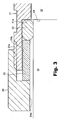
- Fig. 3 is a partially enlarged view of Fig. 1 (e).
- the principal portion of the spindle unit includes main shaft 21, annular elastic member 22, sliding member 23, and sealing nut 24.
- the main shaft 21 is in a cylindrical form for receiving the cutting tool 10 therein.
- threads 21a are formed on its outer surface, and larger inner diameter section 21b having an inner diameter relatively larger than the other portion is formed on its inner surface.
- larger inner diameter section 21b is smaller inner diameter section 21c, with step 21d formed between the larger and smaller inner diameter sections 21b and 21c.
- polygonal cylinder section 21e is formed inside, and threads 21f are formed on the outer surface. These threads 21f are optional, and the outer surface of the rear end portion may be a smooth surface.
- engaging sections of the cutting tool 10 and the main shaft 21 are formed by providing the polygonal prism section 15 at the rear end of the shank of the cutting tool 10 and providing the polygonal cylinder section 21e at the rear end of the main shaft 21.
- the engaging sections may alternatively be formed as engaging sections 60 to 63 as shown in Figs. 4(a) to 4(d).
- cylindrical body 60a having one flat face, cylindrical body 61a having two opposed flat faces, axial body 62a having a cross shaped cross-section, or axial body or bodies 63a extending from one or a plurality of locations, are provided at the rear end of the shank, and a cylindrical section 60b to 63b having a complementary shape to be engaged with the rear end of the cutting tool is provided at the rear end of the main shaft, to thereby form the engaging sections 60 to 63.
- the annular elastic member 22 is made of a material that is elastically deformable by external force, such as rubber or resin materials.
- the sliding member 23 is an annular member, and has an outer diameter that allows insertion of the sliding member 23 into the larger inner diameter section 21b of the main shaft 21, and an inner diameter that allows sliding engagement around the smaller diameter section 13 of the cutting tool 10 and is larger than the larger diameter section 12 of the cutting tool 10.
- the sealing nut 24 screws on the threads 21a on the frond end portion of the main shaft 21, and has annular inner protrusion 24a protruding radially inwards to provide a surface on which the sliding member 23 abuts, and having an inner diameter larger than the diameter of the larger diameter section 12 of the cutting tool 10.
- the steps 14 and 21d are generally aligned with each other, and a gap is formed between the smaller diameter section 13 of the cutting tool 10 and the larger inner diameter section 21b of the main shaft 21.
- the annular elastic member 22 is arranged in the gap to abut to the steps 14 and 21d, and the sliding member 23 is arranged in the gap to abut to the annular elastic member 22.
- the sealing nut 24 is screwed onto the threads 21a in the front end portion of the main shaft 21, so that the inner protrusion 24a abuts to the sliding member 23.
- the sealing nut 24 being screwed, slides the sliding member 23, which in turn presses the annular elastic member 22 to elastically deform.
- the annular elastic member 22 protrudes radially inwardly to pressure contact with the smaller diameter portion 13 and the step 14 of the cutting tool 10, to thereby prevent axial and circumferential movements of the cutting tool 10.
- the annular elastic member 22 is released from the pressure contact with the smaller diameter portion 13 and the step 14 of the cutting tool 10, and clearance is formed between the cutting tool 10 and the annular elastic member 22. Since the diameters of the larger and smaller diameter portions 12 and 13 of the cutting tool 10 are smaller than the inner diameters of the sliding member 23 and the sealing nut 24, the cutting tool 10 may be drawn out of the main shaft 21 without the sliding member 23 and the sealing nut 24 being completely detached from the main shaft 21. Accordingly, the cutting tool 10 may be replaced rapidly.
- the polygonal prism section 15 of the tool 10 engages with the polygonal cylinder section 21e of the main shaft 21, so that relative circumferential movement of the cutting tool 10 in the main shaft 21, such as free spinning, is prevented.
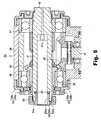
- Fig. 5 shows the spindle unit according to the present invention incorporated in a surgical handpiece. While the principal portion of the embodiment of Fig. 5 is composed of the same elements as those of Fig. 1, some members are formed in slightly different shapes. Specifically, the principal portion of spindle unit 30 in Fig. 5 is composed of main shaft 31, annular elastic member 32, sliding member 33, and sealing nut 34, and is generally the same as the principal portion of the spindle unit in Fig. 1, except for the shape of the sliding member 33 and the manner of engagement between the sliding member 33 and the sealing nut 34.
- the sliding member 33 is an annular member having an inner diameter that allows insertion of a cutting tool (not shown) therein.
- the sliding member 33 has insert portion 33a to be inserted into the larger inner diameter section of the main shaft 31, outer projection 33b axially extending out of the main shaft 31, and flange portion 33c to be engaged with inward protrusion 34a of the sealing nut 34.
- the cutting tool may be drawn out of the main shaft 31 without the sealing nut 34 being completely detached from the main shaft 31. Accordingly, the cutting tool 10 may be replaced rapidly, as with the embodiment of Fig. 1.
- the structure of the spindle unit of Fig. 5 other than its principal portion is briefly explained.
- the main shaft 31 is supported in housing 38 by means of front and rear bearings 36 and 37, which are sealed with bearing seal caps 39.
- Main shaft-side gear 35 is fixed on the outer surface of the main shaft 31, and drive-side gear 40 is arranged to mesh with the main shaft-side gear 35.
- the drive-side gear 40 is rotated by the power transmitted from a drive section (not shown) via drive shaft 41.
- Each of the front and rear bearing seal caps 39 is composed of rotary cap 39a fixed to the main shaft 31, and stationary cap 39b fixed to the housing 38.
- the caps 39a and 39b are arranged with a gap therebetween, which provides a dust preventive labyrinth for preventing intrusion of dust into the bearing.
- the rear end of the main shaft 31 is sealed with axial member 42.
- Fig. 6 shows the spindle unit according to the present invention having a structure for incorporation in a machine tool. While the principal portion of the embodiment of Fig. 6 is composed of the same elements as those of Fig. 1, some members are formed in slightly different shapes and sizes.
- the principal portion of spindle unit 70 in Fig. 6 is composed of main shaft 71, annular elastic member 72, sliding member 73, and sealing nut 74.
- the inward protrusion 74a of the nut 74 abuts to the sliding member 73, and pushes it into the main shaft 71.
- the sliding member 73 presses the annular elastic member 72 to elastically deform it.
- the annular elastic member 72 protrudes radially inwardly to pressure contact with the smaller diameter portion 81 and the step 82 of the cutting tool 80, to thereby prevent axial and circumferential sliding and free spinning of the cutting tool 80.
- the cutting tool 80 may be drawn out of the main shaft 71 without the sealing nut 74 being completely detached from the main shaft 71. Accordingly, the cutting tool 80 may be replaced rapidly, as with the embodiments of Figs. 1 and 5.
- the polygonal prism section 83 of the cutting tool 80 engages with the polygonal cylinder section 71a of the main shaft 71, so that relative circumferential movement of the cutting tool 80 in the main shaft 71, such as free spinning, is prevented.
- the structure of the spindle unit 70 of Fig. 6 other than its principal portion is briefly explained.
- On the rear end of the main shaft 71 is provided linking member 75, to which a drive unit (not shown) is connected to rotate the main shaft 71 by means of the power transmitted from a drive section (not shown) .
- the main shaft 71 is rotatably supported in housing 77 by means of front and rear bearings 76a and 76b.
- the front bearing 76a is sealed with bearing fixing members 78a and bearing seal cap 78b, whereas the rear bearing 76b is sealed with bearing fixing member 79.
- the bearing fixing members 78a and the bearing seal cap 78b are arranged with a gap therebetween, which provides a dust preventive labyrinth for preventing intrusion of dust into the bearing.
Landscapes
- Engineering & Computer Science (AREA)
- Mechanical Engineering (AREA)
- Gripping On Spindles (AREA)
- Sealing Devices (AREA)
- Harvester Elements (AREA)
- Cutting Tools, Boring Holders, And Turrets (AREA)
Applications Claiming Priority (1)
| Application Number | Priority Date | Filing Date | Title |
|---|---|---|---|
| JP2005064699A JP4181556B2 (ja) | 2005-03-09 | 2005-03-09 | 切削工具保持機構及びスピンドルユニット |
Publications (1)
| Publication Number | Publication Date |
|---|---|
| EP1700655A1 true EP1700655A1 (fr) | 2006-09-13 |
Family
ID=36570475
Family Applications (1)
| Application Number | Title | Priority Date | Filing Date |
|---|---|---|---|
| EP06004267A Withdrawn EP1700655A1 (fr) | 2005-03-09 | 2006-03-02 | Mécanisme de support d'outil de coupe et broche |
Country Status (4)
| Country | Link |
|---|---|
| EP (1) | EP1700655A1 (fr) |
| JP (1) | JP4181556B2 (fr) |
| KR (1) | KR20060097644A (fr) |
| CN (1) | CN100556614C (fr) |
Cited By (2)
| Publication number | Priority date | Publication date | Assignee | Title |
|---|---|---|---|---|
| CN108972037A (zh) * | 2018-09-26 | 2018-12-11 | 哈尔滨理工大学 | 一种cfrp加工用高效密封负压可视吸气式内排屑刀柄 |
| US20210106350A1 (en) * | 2015-03-25 | 2021-04-15 | Medtronic Ps Medical, Inc. | Pin drive rotary surgical cutting tools and powered handpieces |
Families Citing this family (2)
| Publication number | Priority date | Publication date | Assignee | Title |
|---|---|---|---|---|
| DE102007029449A1 (de) * | 2007-06-21 | 2008-12-24 | Fischer AG Präzisionsspindeln | Fliehkraftunterstütztes Werkzeugspannsystem |
| CN114148030B (zh) * | 2021-11-30 | 2023-09-01 | 浙江诚达机械股份有限公司 | 一种纸盒成型机 |
Citations (4)
| Publication number | Priority date | Publication date | Assignee | Title |
|---|---|---|---|---|
| US2933321A (en) * | 1958-07-16 | 1960-04-19 | Americo S Cardi | Gun drill holder |
| DE1217262B (de) * | 1959-12-14 | 1966-05-18 | Bauer Carl Fa | Werkzeughalterung fuer eine wahlweise als Bohr- oder Vibrationsbohrmaschine zu benutzende Maschine |
| US3817648A (en) * | 1971-09-03 | 1974-06-18 | Super Cut | Drill shank and chuck assembly for a drill press |
| US4158522A (en) * | 1976-11-11 | 1979-06-19 | Sandvik Aktiebolag | Methods and apparatus for detachably fastening a tool shaft to a tool holder |
-
2005
- 2005-03-09 JP JP2005064699A patent/JP4181556B2/ja not_active Expired - Fee Related
-
2006
- 2006-03-02 EP EP06004267A patent/EP1700655A1/fr not_active Withdrawn
- 2006-03-08 KR KR1020060021779A patent/KR20060097644A/ko not_active Application Discontinuation
- 2006-03-09 CN CNB2006100589543A patent/CN100556614C/zh not_active Expired - Fee Related
Patent Citations (4)
| Publication number | Priority date | Publication date | Assignee | Title |
|---|---|---|---|---|
| US2933321A (en) * | 1958-07-16 | 1960-04-19 | Americo S Cardi | Gun drill holder |
| DE1217262B (de) * | 1959-12-14 | 1966-05-18 | Bauer Carl Fa | Werkzeughalterung fuer eine wahlweise als Bohr- oder Vibrationsbohrmaschine zu benutzende Maschine |
| US3817648A (en) * | 1971-09-03 | 1974-06-18 | Super Cut | Drill shank and chuck assembly for a drill press |
| US4158522A (en) * | 1976-11-11 | 1979-06-19 | Sandvik Aktiebolag | Methods and apparatus for detachably fastening a tool shaft to a tool holder |
Cited By (3)
| Publication number | Priority date | Publication date | Assignee | Title |
|---|---|---|---|---|
| US20210106350A1 (en) * | 2015-03-25 | 2021-04-15 | Medtronic Ps Medical, Inc. | Pin drive rotary surgical cutting tools and powered handpieces |
| US11864784B2 (en) * | 2015-03-25 | 2024-01-09 | Medtronic Ps Medical, Inc. | Pin drive rotary surgical cutting tools and powered handpieces |
| CN108972037A (zh) * | 2018-09-26 | 2018-12-11 | 哈尔滨理工大学 | 一种cfrp加工用高效密封负压可视吸气式内排屑刀柄 |
Also Published As
| Publication number | Publication date |
|---|---|
| CN1830618A (zh) | 2006-09-13 |
| KR20060097644A (ko) | 2006-09-14 |
| CN100556614C (zh) | 2009-11-04 |
| JP2006247764A (ja) | 2006-09-21 |
| JP4181556B2 (ja) | 2008-11-19 |
Similar Documents
| Publication | Publication Date | Title |
|---|---|---|
| KR100211555B1 (ko) | 평행력 장전 베어링을 지니는 콜릿 척 | |
| EP1700655A1 (fr) | Mécanisme de support d'outil de coupe et broche | |
| KR102580289B1 (ko) | 콜렛 홀더와 툴 어댑터 사이의 인터페이스 | |
| EP2682210B1 (fr) | Appareil de guidage de forage et procédé de guidage de forage | |
| JP4977627B2 (ja) | コレット及びロックナット | |
| JP5752999B2 (ja) | 歯科用ハンドピース | |
| JP2001071205A (ja) | キー無しチャック | |
| GB2464796A (en) | Self-tightening drill chuck | |
| US4219330A (en) | Dental handpiece and rotor cartridge replacement assembly therefor | |
| EP2008609B1 (fr) | Pièce à main dentaire | |
| WO2006103651A3 (fr) | Support d'outil a ajustage par contraction | |
| KR20100007666U (ko) | 라이브센터 | |
| US20200038139A1 (en) | Dental treatment instrument for operating a rotational tool | |
| DE102012000437A1 (de) | Spannmechanismus für ein zahnmedizinisches Handstück und zahnmedizinisches Handstück unter Verwendung des Mechanismus | |
| US8197253B2 (en) | Medical or dental handpiece head | |
| EP1329272A2 (fr) | Ecrou de serrage et pince de serrage | |
| JP4898950B1 (ja) | インプラントの固定ねじのゆるみ止め部材 | |
| JPH08108302A (ja) | 工具ホルダー | |
| KR101510112B1 (ko) | 분진 토출구조를 갖는 핸드피스 | |
| JP7089457B2 (ja) | 加工装置 | |
| US5575648A (en) | Dental turbine spindle assembly | |
| KR200458969Y1 (ko) | 핸드피스의 버 고정 척 구조 | |
| EP3949893B1 (fr) | Pièce à main dentaire | |
| JP2504972Y2 (ja) | 軸封装置 | |
| JP2023047816A (ja) | せん断破砕機 |
Legal Events
| Date | Code | Title | Description |
|---|---|---|---|
| PUAI | Public reference made under article 153(3) epc to a published international application that has entered the european phase |
Free format text: ORIGINAL CODE: 0009012 |
|
| AK | Designated contracting states |
Kind code of ref document: A1 Designated state(s): AT BE BG CH CY CZ DE DK EE ES FI FR GB GR HU IE IS IT LI LT LU LV MC NL PL PT RO SE SI SK TR |
|
| AX | Request for extension of the european patent |
Extension state: AL BA HR MK YU |
|
| 17P | Request for examination filed |
Effective date: 20070305 |
|
| AKX | Designation fees paid |
Designated state(s): DE FR IT |
|
| 17Q | First examination report despatched |
Effective date: 20070509 |
|
| STAA | Information on the status of an ep patent application or granted ep patent |
Free format text: STATUS: THE APPLICATION IS DEEMED TO BE WITHDRAWN |
|
| 18D | Application deemed to be withdrawn |
Effective date: 20091001 |