EP1699174B1 - Kommunikationssteuersystem - Google Patents
Kommunikationssteuersystem Download PDFInfo
- Publication number
- EP1699174B1 EP1699174B1 EP04771523.0A EP04771523A EP1699174B1 EP 1699174 B1 EP1699174 B1 EP 1699174B1 EP 04771523 A EP04771523 A EP 04771523A EP 1699174 B1 EP1699174 B1 EP 1699174B1
- Authority
- EP
- European Patent Office
- Prior art keywords
- communication
- section
- data
- packet
- time
- Prior art date
- Legal status (The legal status is an assumption and is not a legal conclusion. Google has not performed a legal analysis and makes no representation as to the accuracy of the status listed.)
- Expired - Lifetime
Links
- 238000004891 communication Methods 0.000 title claims description 356
- 230000005540 biological transmission Effects 0.000 claims description 86
- 239000000872 buffer Substances 0.000 claims description 48
- 125000004122 cyclic group Chemical group 0.000 claims description 29
- 230000001360 synchronised effect Effects 0.000 claims description 2
- 238000010586 diagram Methods 0.000 description 16
- 238000000034 method Methods 0.000 description 14
- 238000012544 monitoring process Methods 0.000 description 10
- 238000003860 storage Methods 0.000 description 7
- 238000004886 process control Methods 0.000 description 4
- 230000004044 response Effects 0.000 description 4
- 238000005516 engineering process Methods 0.000 description 2
- 230000006870 function Effects 0.000 description 2
- 230000008569 process Effects 0.000 description 2
- 238000012369 In process control Methods 0.000 description 1
- 229920001131 Pulp (paper) Polymers 0.000 description 1
- 229910000831 Steel Inorganic materials 0.000 description 1
- 230000005856 abnormality Effects 0.000 description 1
- 230000008859 change Effects 0.000 description 1
- 230000001419 dependent effect Effects 0.000 description 1
- 238000010965 in-process control Methods 0.000 description 1
- 239000007788 liquid Substances 0.000 description 1
- 230000014759 maintenance of location Effects 0.000 description 1
- 230000006855 networking Effects 0.000 description 1
- 239000003208 petroleum Substances 0.000 description 1
- 238000011897 real-time detection Methods 0.000 description 1
- 239000010959 steel Substances 0.000 description 1
Images


Classifications
-
- H—ELECTRICITY
- H04—ELECTRIC COMMUNICATION TECHNIQUE
- H04L—TRANSMISSION OF DIGITAL INFORMATION, e.g. TELEGRAPHIC COMMUNICATION
- H04L12/00—Data switching networks
- H04L12/28—Data switching networks characterised by path configuration, e.g. LAN [Local Area Networks] or WAN [Wide Area Networks]
- H04L12/40—Bus networks
- H04L12/40143—Bus networks involving priority mechanisms
- H04L12/4015—Bus networks involving priority mechanisms by scheduling the transmission of messages at the communication node
-
- H—ELECTRICITY
- H04—ELECTRIC COMMUNICATION TECHNIQUE
- H04L—TRANSMISSION OF DIGITAL INFORMATION, e.g. TELEGRAPHIC COMMUNICATION
- H04L12/00—Data switching networks
- H04L12/28—Data switching networks characterised by path configuration, e.g. LAN [Local Area Networks] or WAN [Wide Area Networks]
- H04L12/40—Bus networks
- H04L12/40006—Architecture of a communication node
- H04L12/40032—Details regarding a bus interface enhancer
-
- H—ELECTRICITY
- H04—ELECTRIC COMMUNICATION TECHNIQUE
- H04L—TRANSMISSION OF DIGITAL INFORMATION, e.g. TELEGRAPHIC COMMUNICATION
- H04L12/00—Data switching networks
- H04L12/28—Data switching networks characterised by path configuration, e.g. LAN [Local Area Networks] or WAN [Wide Area Networks]
- H04L12/40—Bus networks
- H04L12/403—Bus networks with centralised control, e.g. polling
- H04L12/4035—Bus networks with centralised control, e.g. polling in which slots of a TDMA packet structure are assigned based on a contention resolution carried out at a master unit
Definitions
- the present invention relates to a communication control system for controlling communications in an industrial application such as process control.
- the invention in particular relates to a communication control system to which a device has been applied for providing real time communications by the use of the Ethernet (registered trademark) and a standard communication protocol such as UDP/IP (User Datagram Protocol/Internet Protocol).
- Ethernet registered trademark
- UDP/IP User Datagram Protocol/Internet Protocol
- Communications in an industrial application includes, for example, communications in process control.
- Process control is made by a distributed control system.
- a distributed control system is used for plant operation control in a wide range of fields such as petroleum chemistry, steel, paper pulp, and electric power. Communications in an industrial application will be described by taking as an example a distributed control system.
- Fig. 1 shows an exemplary configuration of a general distributed control system.
- an operation monitoring apparatus 1 and a controller 2 are connected to a control bus 3.
- the controller 2 controls a plant 4 under the monitoring of the operation monitoring apparatus 1.
- the operation monitoring apparatus 1 is in charge of plant operation and monitoring.
- the operation monitoring apparatus 1 displays a screen for control operation and monitoring.
- a plurality of controllers is distributed in the plant.
- the operation monitoring apparatus 1 and the controller 2 communicates with each other via a ⁇ the control bus 3 to control the plant.
- Sensor devices 5, 6 in the plant 4 detect process values of temperature, pressure, liquid level and the like. Degrees of openings of valves 7, 8 are controlled by way of an operation signal provided from the controller 2. An analog signal of 1 to 20mA and 1 to 5V output from the sensor devices 5, 6 is input to the controller 2. Based on this input, the control unit (not shown) in the controller 2 performs control arithmetic operation and obtains an operation quantity. The operation quantity is output as an analog signal of 1 to 20mA and 1 to SV. This output is used to control the degree of opening of the valves 7, 8. For example, by controlling the degree of valve opening on a reaction oven, the process quantities of temperature and pressure are controlled.
- a control bus in a conventional distributed control system is dedicated to process control.
- the protocol used by the control bus has been dedicated to process control.
- Patent document 1 describes a communication system that determines whether an identifier attached to receive data takes priority and performs priority control of communications in accordance with the determination result thus assuring the real time properties of communications of priority data.
- Patent document 1 Japanese patent No. 3457636
- communication station A In the conventional communication system, data exchanged between communication stations is fixed. For example, given communication stations A, B, C and D, communication station A is set to exchange data with communication stations B, C and D. Communication station A is not designed to exchange data with communication station C alone. Communication station A must change its setting in order to exchange data with communication station C alone.
- An object of the invention is to provide a communication control system that meets the needs of industrial applications in terms of real time properties as well as scalability and flexibility by implementing a real time communication protocol using a UDP service on the Ethernet (registered trademark) and a standard communication protocol such as UDP/IP.
- Fig. 2 is a block diagram showing an embodiment of the invention.
- a communication station 10 is connected to a communication path 20.
- the communication path 20 is for example a control bus in a distributed control system.
- the communication station 10 performs communications in accordance with a standard protocol.
- a standard protocol is for example UDP or IP.
- the communication station 10 is in charge of multiplex communications by a time division of a communication band.
- a time slot assignment section 101 divides into time slots a communication cycle having a certain time length and serving as a base cycle of time division, and assigns a set of communication stations and a type of communication section to each time slot.
- a set of communication stations is generated by grouping communication stations based on the address of each communication station.
- Grouping methods include grouping based on a network address and grouping based on a MAC (Media Access Control) address.
- the types of communication section include time-synchronous communications, 1-to-N non-cyclic data communications (N being an integer equal to or more than 2), 1-to-N cyclic data communications, 1-to-1 non-cyclic data communications, and 1-to-1 cyclic data communications.
- 1-to-1 non-cyclic data communications include acknowledgment type communication and negative acknowledgment type communication.
- a receiving station In the acknowledgment type communication, a receiving station returns an acknowledgment to a transmitting station on successful receipt of data. In the negative acknowledgment type communication, a receiving station returns a negative acknowledgment to a transmitting station on failure in receipt of data.
- Storage section 102 stores assignment information 103 indicating the set of communication station and the type of communication section assigned to each time slot.
- Time-division multiplex communication section 104 performs communications within the corresponding time slot in accordance with the set of communication station and the type of communication section assigned by the time slot assignment section 101.
- time-division multiplex communication section 104 are provided communication section for performing all types of communications (time-synchronous communications, 1-to-N non-cyclic data communications, 1-to-N cyclic data communications, 1-to-1 non-cyclic data communications, and 1-to-1 cyclic data communications).
- Each communication station is provided with time-synchronous communication section 105 and timer section 106.
- the time-synchronous communication section 105 transmits a time-synchronous communication frame to each station, the timer section 106 of all communication stations are synchronized. This synchronizes the time slots of all communication stations.
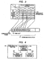
- Fig. 3 is an explanatory diagram showing how to assign assigning information to time slots.
- assignment information 103 is given in a table format.
- the vertical axis of the table represents the sets of communication stations G1 through G4 while the horizontal axis represents the sets of communication section C1 through C4.
- a communication cycle 111 in a communication frame 110 is a basic cycle having a certain length.
- the communication cycle 111 is divided into time slots 112.
- Each time slot is assigned a set of communication stations and a type of communication section. For example, a first time slot is assigned a set of communication stations G1 and a set of communication section C1.
- a second time slot is assigned a set of communication stations G2 and a set of communication section C2.
- Each time slot performs communications in accordance with the assigned set of communication stations and type of communication section.
- a communication frame is divided into time slots for multiplex communications.
- a communication cycle is divided into time slots and each slot is assigned a proper communication system in accordance with the characteristics of information. This provides a communication control system that satisfies the needs of industrial applications in terms of real time properties, scalability and flexibility.
- Fig. 4 is a block diagram showing another embodiment of the invention.
- Fig. 4 shows an exemplary configuration of the communication section provided in the time-division multiplex communication section 104.
- communication section 30 is communication section for performing 1-to-N non-cyclic data communications.
- Data transmission section 301 broadcasts data packets to a group aggress as the destinations of a plurality of communication stations.
- a group address may be generated from a network address or MAC address.
- the data reception section 302 receives the transmitted data packet.
- An address file 303 stores a group address 304 used for communications.
- Fig. 5 is a block diagram showing another embodiment of the invention.
- Fig. 5 shows an exemplary configuration of the communication section provided in the time-division multiplex communication section 104.
- communication section 40 is communication section for performing 1-to-N cyclic data communications. While a communication station sis not shown in Fig. 5 for the purpose of clarity, the communication section 40 is located in a communication station.
- Data transmission section 401 broadcasts data packets in a fixed cycle to a group address as the destinations of a plurality of communication stations.
- Receive buffers 402a and 402b stores the reception time of a received data packet and the data packet as a pair.
- the data reception section 403 attaches the reception time to each of the received data packets and stores the data packets into the receive buffers 402a and 402b packets by packets.
- the reception time is acquired from timer section 404.
- An address file 405 stores a group address 406 used for communications.
- Receive buffer reading section 407 reads a data packet from a receive buffer 402a or 402b whichever contains the latest reception time.
- the receive buffer reading section 407 sends the read data packets to a higher-level PC 430 via a communication path 420.
- the receive buffer reading section 407 completes a readout procedure within a time shorter than the cycle of broadcast communications by the data transmission section 401.
- Data packets stored into the receive buffers 402a and 402b are those transmitted from another communication station via broadcast communications.
- Fig. 5 assume that data packets a, b, c, d are transmitted from the communication path 20 in this order and are received by the packet reception section 403 and that the destination address of each data packet is one the communication section 40 belongs to.
- the packet reception section 403 attaches reception times t1, t2, t3, t4 to the data packets a, b, c, d.
- the first received data packet a and the reception time t1 are stored in the receive buffer 402a.
- the second received data packet b and the reception time t2 are stored in the receive buffer 402b.
- the receive buffer reading section 407 reads a data packet from a receive buffer 402a or 402b whichever contains the latest reception time.
- the receive buffer reading section 407 reads the data packet a and the reception time t1 from the receive buffer 402a.
- the reception time t2 is the latest time.
- the receive buffer reading section 407 reads the data packet b and the reception time t2 from the receive buffer 402b.
- the data packet c/reception time t3 pair and the data packet d/reception time t4 pair are read in this order.
- the receive buffer reading section 407 completes a readout procedure within a time shorter than the cycle data packets are transmitted (cycle of broadcast communications by the data transmission section 401). Data packets a, b, c, d are read in this order.
- the receive buffer reading section 407 transmits the read data packets and reception times to the higher-level PC 430. In other words, the latest data is sent to the PC 430.
- a latest data packet which allows a higher-level side to monitor the latest data. For example, it is possible to monitor the latest state of a switch at the monitor point from a higher-level side.
- Fig. 6 is a block diagram showing another embodiment of the invention.
- Fig. 6 shows an exemplary configuration of communication section provided in the time-division multiple communication section 104.
- communication section 50 is communication section for performing 1-to-1 non-cyclic immediate response data communications. While a communication station sis not shown in Fig. 6 for the purpose of clarity, the communication section 50 is located in a communication station.
- Data transmission section 501 transmits data packets to a single communication station and retransmits the data packet in case a normal acknowledgment is not returned from the receiving station within a predetermined time.
- the data transmission section 501 recognizes that the predetermined time has elapsed based on the time count of the timer section 502.
- the data reception section 503 transmits a normal acknowledgment on normally receiving a data packet.
- the data transmission section 501 retransmits a data packet independently of a time slot assigned to the home communication station.
- the data reception section 503 transmits a normal acknowledgment independently of a time slot assigned to the home communication station.
- Fig. 7 shows a connection example of a communication station.
- communication stations 1A, 1B, 1C are connected to a communication path 20. These communication stations 1A, 1B, 1C have respectively assigned time slots.
- the communication stations 1A, 1B, 1C uses the communication path 20 to perform time-division-based communications.
- the communication stations 1A, 1B, 1C are respectively referred to as Communication Station A, Communication Station B, and Communication Station C.
- Fig. 8 is a time chart showing the communication procedure of the communication station in Fig. 7 .
- Communication Station A, Communication Station B, and Communication Station C are respectively assigned time slots TA, TB, TC (TC is not shown).
- Communication Station A transmits a data packet to another communication station.
- Communication Station A transmits a data packet 1 to Communication Station C.
- Communication Station C returns a normal acknowledgment 510 to Communication Station A even in the time zone of the time slot TA.
- Communication Station C returns a normal acknowledgment 510 independently of a time slot of the home communication station.
- Communication Station B and Communication Station C transmit a data packet in the time slots TB and TC.
- Communication Station A has transmitted a data packet 2 to Communication Station C in the time slot TA and a normal acknowledgment from Communication station C is lost and a normal acknowledgment is not returned from Communication Station C after a predetermined time has elapsed.
- Communication Station A retransmits a data packet independently of the time slot TA.
- Communication Station A retransmits the data packet 2 in the time slot TB to Communication Station C in step 520.
- Communication Station C returns a normal acknowledgment in the time slot TB.
- retransmission of a data packet and normal acknowledgment are made independently of the time slots of the communication stations involved. This prevents an increase in the response delay time of communications even in an environment where there are a larger number of communication stations. It is thus possible to provide a communication control system that is suitable for a large-sized communication system.
- Fig. 9 is a block diagram showing another embodiment of the invention.
- Fig. 9 shows an exemplary configuration of communication section provided in the time-division multiple communication section 104.
- communication section 60 is communication section for performing 1-to-1 non-cyclic negative acknowledgment data communications.
- Data transmission section 601 transmits a data packet with a sequence number attached, the sequence number changed each time transmission is made.
- Data reception section 602 checks the sequence number attached to a data packet each time the data packet is received and transmits a negative acknowledgment packet to a transmitting station when detecting a lost sequence number as a result of checking.
- Storage section 603 stores a sequence number 604 used for communications.
- the data reception section 602 on detecting a lost sequence number, transmits a negative acknowledgment packet with a sequence number specifying the latest normally received data packet attached.
- Data transmission section 601 in the transmitting station on receiving a negative acknowledgment packet, sequentially retransmits data packets starting with the undelivered data packet specif ied by the sequence number attached to the negative acknowledgment packet.
- the data transmission section 601 transmits a delivery acknowledgment packet when not transmitting subsequent data packets for a predetermined time on completion of data packet transmission. In case the sequence number indicated by an acknowledgment packet returned from the receiving station in response to the delivery acknowledgment packet does not represent the last transmitted data packet, the data transmission section 601 sequentially retransmits data packets starting with the undelivered data packet specified by the returned acknowledgment packet.
- the data reception section 602 on receiving the delivery acknowledgment packet, returns to the transmitting station an acknowledgment packet to which a sequence number specifying the last received data packet is attached.
- Fig. 10 is a flowchart showing an example of communication procedure in the embodiment shown in Fig. 9 .
- the data transmission section 601 in the transmitting station sequentially transmits to the receiving station data packets with sequence numbers attached.
- the data transmission section 601 changes the sequence numbers to be attached to data packets each time transmission is made: S1, S2, and so on.
- the data reception section 602 in the receiving station detects the loss of the sequence number S6 with the timing the data of the sequence number S7 is received.
- the data reception section 602 in the receiving station on receiving the sequence number S7, immediately informs the transmitting station a negative acknowledgment packet S6' including the information on the sequence number S6 of the lost data. Receiving this notice, the transmitting station retransmits data packets in the order of S6, S7, S8 and so on staring with the sequence number S6.
- the data packet of the sequence number S7 is received twice by the receiving communication station although duplicate data is overwritten on a received data file so that no problems occur.
- communications in the embodiment in Fig. 9 are negative acknowledgment type communications where a receiving party notifies a sending party an abnormality of any lost receive packet.
- Fig. 11 is a flowchart showing the communication procedure for a delivery acknowledgment packet and an acknowledgment packet in the embodiment shown in Fig. 9 .
- a delivery acknowledgment packet including S7 is transmitted from the transmitting station to the receiving station.
- the receiving station acknowledges reception of S7 and transmits an acknowledgment packet S7 including information on S7 to the transmitting station.
- a transmitting station and a receiving station know the latest transmission-complete sequence number thus retaining the equivalency of the sequence number of next data packet transmission.
- both stations own common information on sequence numbers.
- a common rule is owned by a transmitting station and a receiving station that sequence numbers are incremented from 1 and the maximum value is followed by 1. Sequence numbers may not be incremented from 1. For example, sequence numbers may be even numbers or odd numbers that are incremented, or a randomly variable numbers, as long as a common rule is owned by a transmitting station and a receiving station.
- the common rule is owned by the transmitting station and the receiving station in storage section 603.
- the data reception section 602 may transmit a negative acknowledgment packet and an acknowledgment packet independently of a corresponding time slot.
- the communication procedure used in this case is similar to the communication procedure shown in Fig. 7 .
- the receiving station checks the sequence number of each data packet and transmits a negative acknowledgment packet to the transmitting station on detecting a loss of a sequence number.
- Fig. 12 is a block diagram showing another embodiment of the invention.
- Fig. 12 shows an exemplary configuration of communication section provided in the time-division multiple communication section 104.
- communication section 70 is communication section for performing 1-to-1 cyclic data communications.
- transmission requesting section 701 requests cyclic transmission of data packets addressed to a specified communication station by way of a start request packet based on a data acquisition request.
- Halt requesting section 702 requests halt of cyclic transmission of data packets by way of a halt request packet
- Data transmission section 703 starts transmission of a data packet specified by the start request packet to a requesting communication station in a cycle specified by the start request packet on receiving the start request packet.
- the data transmission section 703 stops transmission of the data packet on receiving a halt request packet.
- Data reception section 704 receives the data packet.
- Fig. 13 shows an exemplary configuration of the data reception section 704.
- receive buffers 720a, 720b, packet reception section 721, timer section 722 and reception buffer reading section 723 has respectively the same configuration as the receive buffers 402a, 402b, packet reception section 403, timer section 404 and reception buffer reading section 407.
- the data reception section 704 also attaches a reception time to a received data packet and stores data packets into a plurality of receive buffers one by one.
- the data reception section 704 reads a data packet with the latest reception time attached from the plurality of receive buffers and sends it to a higher-level side.
- the communication station does not transmit data packets on its own initiative but transmits data packets to a requesting communication station on receiving a data acquisition request.
- the communication station stops transmission. That is, the communication station communicates with another target communication station only when necessary. This reduces the overall communication volume compared with 1-to-N broadcast communications thus reducing the memory area of the communication station. This configuration is particularly effective for a larger number of communication stations or large amount of communication data.
- Fig. 14 is a block diagram showing another embodiment of the invention.
- a communication station 80 is connected to a communication path 20.
- the communication station performs communications in accordance with a standard protocol such as UDP or IP.
- Transmission queue section 801a through 801c are present between the second and third layers of an OSI (Open Systems Interconnection) layer model and constitute a queue of transmission packets. Such transmission queue section 801a through 801c are provided per communication type.
- OSI Open Systems Interconnection
- Reception queue section 802a through 802c are present between the second and third layers of an OSI (Open Systems Interconnection) layermodel and constitute a queue of reception packets. Such reception queue section 802a through 802c are provided per communication type.
- OSI Open Systems Interconnection
- Transmission section 803 has functions of the first and second layers of an OSI layer model and transmits the packets in the transmission queue section 801a through 801c in a predetermined order of priority, with priority information corresponding to the transmission queue section 801a through 801c attached.
- Reception section 804 has functions of the first and second layers of an OSI layer model and divides and stores received packets among the reception queue section 802a through 802c in accordance with the attached priority information.
- Reading section 805 reads data stored in the reception queue section 802a through 802c in accordance with a predetermined order of priority and sends the data to a higher-level PC 430.
- the transmission queue section 801a, 801b, 801c have priorities in this descending order.
- the transmission queue section 801a, 801b, 801c are respectively provided queues for high-priority data, medium-priority data and low-priority data.
- the reception queue section 802a, 802b, 802c have priorities in this descending order.
- the reception queue section 802a, 802b, 802c are respectively provided queues for high-priority data, medium-priority data and low-priority data.
- the transmission section 803 executes, for example, transmission processing of the transmission queue section 801b when data is absent in the transmission queue section 801a.
- the reading section 805 executes the receptionprocessing of the reception queue section 802c when data is absent in the reception queue section 802a, 802b.
- Time-division multiplex communications using the time slots of the embodiment shown in Fig. 2 may be performed in the embodiment shown in Fig. 14 .
- buffers given proprieties are provided. This makes it possible for priority data to surpass non-priority data on a transmission path that requires real time properties, thereby allowing real time communications of priority data.
- a communication station is present on an operation monitoring apparatus or a controller of a distributed control system.
Landscapes
- Engineering & Computer Science (AREA)
- Computer Networks & Wireless Communication (AREA)
- Signal Processing (AREA)
- Communication Control (AREA)
- Data Exchanges In Wide-Area Networks (AREA)
- Small-Scale Networks (AREA)
- Time-Division Multiplex Systems (AREA)
- Synchronisation In Digital Transmission Systems (AREA)
- Mobile Radio Communication Systems (AREA)
Claims (17)
- Kommunikationssteuersystem, das eine Kommunikationsstation veranlasst, Multiplexkommunikation basierend auf einer Zeitverschachtelung eines Kommunikationsbandes durchzuführen, wobei das Kommunikationssteuersystem umfasst:ein zeitliches Zuordnungssegment (101), welches einen Kommunikationszyklus (111) als einen Zeitverschachtelungs-Basiszyklus in Zeitschlitze (112) unterteilt und jedem der Zeitschlitze eine Gruppe von Kommunikationsstationen und einen Kommunikationssegmenttyp zuordnet; undein Zeitverschachtelungs-Multiplexkommunikationssegment (104), welches Kommunikation innerhalb einer Periode des Zeitschlitzes entsprechend der Gruppe von Kommunikationsstationen und eines durch das zeitliche Zuordnungssegment zugeordneten Kommunikationssegmenttyps durchführt,wobei jede Kommunikationsstation mit einem Zeitgebersegment (106) und einem zeitsynchronen Kommunikationssegment (105) ausgerüstet ist,der Typ des Kommunikationssegments zeitsynchrone Kommunikation und nichtzyklische 1 zu 1-Datenkommunikation enthält,das zeitsynchrone Kommunikationssegment zeitsynchrone Kommunikation durch Verwendung des Zeitschlitzes durchführt, in welchem die zeitsynchrone Kommunikation zugeordnet ist, undwenn das zeitsynchrone Kommunikationssegment an jede Kommunikationsstation einen Kommunikationsübertragungsblock überträgt, die Zeit des Zeitgebersegments jeder Kommunikationsstation und die Zeitschlitze aller Kommunikationsstationen synchronisiert werden.
- Kommunikationssteuersystem nach Anspruch 1, wobei die Gruppe von Kommunikationsstationen durch Gruppierung der Kommunikationsstationen basierend auf Adressen der jeweiligen Kommunikationsstationen erzeugt wird.
- Kommunikationssteuersystem nach Anspruch 1, wobei die nichtzyklische 1 zu 1-Datenkommunikation eine Bestätigungskommunikation, welche die nichtzyklische 1 zu 1-Datenkommunikation ist und in der eine Empfangsstation eine Bestätigung an eine Übertragungsstation zurückgibt, wenn die Empfangsstation normalerweise Daten empfängt, und/oder eine negative Bestätigungskommunikation ist, welche die nichtzyklische 1 zu 1-Datenkommunikation ist und in der die Empfangsstation eine negative Bestätigung an die Übertragungsstation zurückgibt, wenn die Empfangsstation die Daten nicht normal empfangen kann.
- Kommunikationssteuersystem nach Anspruch 1, wobei das Kommunikationssegment des Weiteren ausgelegt ist, nicht zyklische 1 zu N-Datenkommunikation durchzuführen, wobei N eine ganze Zahl gleich oder größer als 2 ist, und wobei
das Kommunikationssegment umfasst:ein Datenübertragungssegment zum Broadcasting von Datenpaketen an eine Gruppenadresse als Zielorte einer Vielzahl von Kommunikationsstationen; undeine Datenempfangsstation zum Empfangen eines übertragenen Datenpakets, wenn eine Zieladresse des übertragenen Datenpakets eine Gruppenadresse ist, zu der die Kommunikationsstation gehört. - Kommunikationssteuersystem nach Anspruch 1, wobei das Kommunikationssegment des Weiteren ausgelegt ist, zyklische 1 zu N-Datenkommunikation durchzuführen, wobei N eine ganze Zahl gleich oder größer als 2 ist, und wobei
das Kommunikationssegment umfasst:ein Datenübertragungssegment zum Broadcasting von Datenpaketen in einem festgelegten Zyklus an eine Gruppenadresse als Zielorte einer Vielzahl von Kommunikationsstationen;eine Vielzahl von Empfangspuffern, von denen jeder die Empfangszeit eines empfangenen Datenpakets und das Datenpaket als ein Paar speichert,ein Paketempfangssegment, welches die Empfangszeit für das empfangene Datenpaket reserviert und die Datenpakete einzeln nacheinander zu der Vielzahl von Empfangspuffern sequenziell speichert, wenn eine Zieladresse des empfangenen Datenpakets eine Gruppenadresse ist, zu der die häusliche Kommunikationsstation gehört; undein Empfangspuffer-Lesesegment, welches das Datenpaket von dem Empfangspuffer liest, das die letzte Empfangszeit zwischen der Vielzahl von Empfangspuffern aufweist, das Auslesen in einer Periode, die kürzer als der Zyklus des Broadcastings ist, abschließt und das Datenpaket zu einer Seite mit höherer Ebene sendet. - Kommunikationssteuersystem nach Anspruch 1, wobei das Kommunikationssegment ein Kommunikationssegment ist, um nichtzyklische 1 zu 1-Datenkommunikation durchzuführen, und
das Kommunikationssegment umfasst:ein Datenübertragungssegment zur Übertragung eines Datenpakets an eine einzelne Kommunikationsstation, und das Datenpaket in dem Fall zurück überträgt, bei dem eine normale Bestätigung von einer Empfangsstation innerhalb einer vorgegebenen Zeit nicht zurückgeführt wird; undein Datenempfangssegment zur Übertragung einer normalen Bestätigung, wenn ein Datenpaket normal empfangen wird. - Kommunikationssteuersystem nach Anspruch 6, wobei das Datenübertragungssegment das Datenpaket in einem Zeitschlitz unabhängig von der Zuordnung der Gruppe von Kommunikationsstationen an die Zeitschlitze zurück überträgt.
- Kommunikationssteuersystem nach Anspruch 6, wobei das Datenempfangssegment die normale Bestätigung in einem Zeitschlitz unabhängig von der Zuordnung der Gruppe von Kommunikationsstationen an die Zeitschlitze überträgt.
- Kommunikationssteuersystem nach Anspruch 1, wobei das Kommunikationssegment ein Kommunikationssegment zur Durchführung von nichtzyklischer 1 zu 1-Datenkommunikation und einer negativen Bestätigungskommunikation ist, und wobei
das Kommunikationssegment umfasst:ein Datenübertragungssegment zum Übertragen eines Datenpakets mit einer Sequenznummer, die reserviert wird, wobei die Sequenznummer für jede Übertragung geändert wird; undein Datenempfangssegment, welches eine für ein Datenpaket reservierte Sequenznummer jedes Mal prüft, wenn das Datenpaket empfangen wird, und ein negatives Bestätigungspaket an eine Übertragungsstation überträgt, wenn im Ergebnis einer Prüfung eine verlorengegangene Sequenznummer detektiert wird,wobei das Datenempfangssegment eine Sequenznummer, die das Datenpaket kennzeichnet, das normalerweise als letztes empfangen wird, für das negative Bestätigungspaket reserviert,das Datenübertragungssegment sequenziell Datenpakete beginnend mit einem nicht abgegebenen Datenpaket zurück überträgt, das durch die für das negative Bestätigungspaket reservierte Sequenznummer festgelegt ist, wenn das Datenübertragungssegment das negative Bestätigungspaket empfängt. - Kommunikationssteuersystem nach Anspruch 1, wobei das Kommunikationssegment ein Kommunikationssegment zur Durchführung von nichtzyklischer 1 zu 1-Datenkommunikation und einer negativen Bestätigungskommunikation ist, und
das Kommunikationssegment umfasst:ein Datenübertragungssegment zur Übertragung eines Datenpakets mit einer reservierten Sequenznummer, wobei die Sequenznummer für jede Übertragung geändert wird; undein Datenempfangssegment, welches eine Sequenznummer, die für ein Datenpaket reserviert wird, jedes Mal prüft, wenn das Datenpaket empfangen wird, und ein negatives Bestätigungspaket an eine Übertragungsstation überträgt, wenn im Ergebnis einer Prüfung eine verlorengegangene Sequenznummer detektiert wird,das Datenübertragungssegment ein Zustellungsbestätigungspaket an eine Empfangsstation überträgt, wenn das Datenübertragungssegment ein nachfolgendes Datenpaket für eine vorgegebene Zeit bei Beendigung der Übertragung der Datenpakete nicht überträgt, und das Datenübertragungssegment sequenziell Datenpakete beginnend mit einem nicht abgegebenen Datenpaket, das durch das zurückgeführte Bestätigungspaket festgelegt ist, zurücküberträgt, wenn eine durch ein zurückgeführtes Bestätigungspaket festgelegte Sequenznummer das zuletzt übertragene Datenpaket nicht anzeigt, unddas Datenempfangssegment an die Übertragungsstation ein Bestätigungspaket zurückführt, für das eine das letzte empfangene Datenpaket festlegende Sequenznummer reserviert ist, wenn das Datenempfangssegment das Zustellungsbestätigungspaket empfängt. - Kommunikationssteuersystem nach Anspruch 9 oder 10, wobei das Datenempfangssegment eine Übertragung des negativen Bestätigungspakets und des Bestätigungspakets unabhängig von der Zuordnung der Gruppe von Kommunikationsstationen zu den Zeitschlitzen durchführt.
- Kommunikationssteuersystem nach Anspruch 1, wobei das Kommunikationssegment des Weiteren ausgelegt ist, zyklische 1 zu 1-Datenkommunikation durchzuführen, und wobei
das Kommunikationssegment umfasst:ein Übertragungsanforderungssegment zur Anforderung von zyklischer Übertragung eines Datenpakets, das an eine festgelegte Kommunikationsstation adressiert ist, durch ein Startanforderungspaket, basierend auf einer Datenerfassungsanforderung;ein Stoppanforderungssegment zur Anforderung des Stopps einer zyklischen Übertragung des Datenpakets durch ein Stoppanforderungspaket;ein Datenübertragungssegment, welches, wenn das Startanforderungspaket empfangen wird, die Übertragung eines durch das Startanforderungspaket festgelegten Datenpakets an eine Kommunikationsstation einer anfordernden Quelle in einem durch das Startanforderungspaket festgelegten Zyklus beginnt, und die Übertragung des Datenpakets bei Empfang eines Stoppanforderungspakets stoppt; undein Datenempfangssegment zum Empfang des Datenpakets,wobei das Datenempfangssegment umfasst:eine Vielzahl von Empfangspuffern, von denen jeder die Empfangszeit des empfangenen Datenpakets und des Datenpakets als ein Paar speichert;ein Paketempfangssegment, welches die Empfangszeit für das empfangene Datenpaket reserviert und sequenziell die Datenpakete einzeln nacheinander in die Vielzahl von Empfangspuffern speichert; undein Empfangspuffer-Lesesegment, welches das Datenpaket aus dem Empfangspuffer mit der letzten Empfangszeit unter der Vielzahl von Empfangspuffern liest, das Auslesen in einer Periode abschließt, die kürzer ist als der durch das Startanforderungspaket festgelegte Zyklus, und das Datenpaket zu einer Seite mit höherer Ebene sendet. - Kommunikationssteuersystem nach Anspruch 1, welches Multiplexkommunikation mit Zeitverschachtelung unter Verwendung der Zeitschlitze durchführt, wobei das Kommunikationssteuersystem umfasst:eine Vielzahl von Übertragungswarteschlangensegmenten, welche zwischen vorgegebenen Schichten eines OSI-Schichtenmodells bestehen, ist für jeden Kommunikationstyp vorgesehen und bildet eine Warteschlange von Übertragungspaketen;eine Vielzahl von Warteschlangensegmenten, welche zwischen vorgegebenen Schichten des OSI-Schichtenmodells bestehen, ist für jeden Kommunikationstyp vorgesehen und bildet eine Warteschlange von Empfangspaketen;ein Übertragungssegment zur Übertragung von Paketen in der Vielzahl von Übertragungswarteschlangensegmenten entsprechend einer vorgegebenen Prioritätsreihenfolge mit Prioritätsinformationen, die dem reservierten Übertragungswarteschlangensegment entsprechen;ein Empfangssegment zur Verteilung und Speicherung von empfangenen Paketen in der Vielzahl von Empfangswarteschlangensegmenten entsprechend den Prioritätsinformationen; undein Lesesegment, welches Daten liest, die in der Vielzahl von Empfangswarteschlangensegmenten entsprechend einer vorgegebenen Prioritätsreihenfolge gespeichert sind und die Daten an eine Seite mit höherer Ebene sendet.
- Kommunikationssteuersystem nach Anspruch 13, wobei das Übertragungssegment Übertragungsverarbeitung eines spezifischen Übertragungswarteschlangensegments unter der Vielzahl von Übertragungswarteschlangensegmenten in einem Fall ausführt, wo keine Daten in dem Übertragungswarteschlangensegment vorhanden sind, die gegenüber dem spezifischen Übertragungswarteschlangensegment höhere Priorität aufweisen.
- Kommunikationssteuersystem nach Anspruch 13, wobei das Lesesegment das Lesen eines spezifischen Empfangswarteschlangensegments unter der Vielzahl von Empfangswarteschlangensegmenten in einem Fall ausführt, wo keine Daten in dem Empfangswarteschlangensegment vorhanden sind, die gegenüber dem spezifischen Empfangswarteschlangensegment höhere Priorität aufweisen.
- Kommunikationssteuersystem nach einem der Ansprüche 13 bis 15, wobei das Übertragungswarteschlangensegment und das Empfangswarteschlangensegment zwischen einer zweiten Schicht und einer dritten Schicht eines OSI-Schichtenmodells vorhanden sind.
- Kommunikationssteuersystem nach Anspruch 1, wobei Kommunikation gemäß UDP, User Datagram Protocol, oder IP, Internetprotokoll, durchgeführt wird.
Applications Claiming Priority (2)
| Application Number | Priority Date | Filing Date | Title |
|---|---|---|---|
| JP2003424540A JP3723980B2 (ja) | 2003-12-22 | 2003-12-22 | 通信制御システム |
| PCT/JP2004/011538 WO2005062537A1 (ja) | 2003-12-22 | 2004-08-11 | 通信制御システム |
Publications (3)
| Publication Number | Publication Date |
|---|---|
| EP1699174A1 EP1699174A1 (de) | 2006-09-06 |
| EP1699174A4 EP1699174A4 (de) | 2012-04-25 |
| EP1699174B1 true EP1699174B1 (de) | 2016-10-05 |
Family
ID=34708786
Family Applications (1)
| Application Number | Title | Priority Date | Filing Date |
|---|---|---|---|
| EP04771523.0A Expired - Lifetime EP1699174B1 (de) | 2003-12-22 | 2004-08-11 | Kommunikationssteuersystem |
Country Status (5)
| Country | Link |
|---|---|
| US (1) | US8054850B2 (de) |
| EP (1) | EP1699174B1 (de) |
| JP (1) | JP3723980B2 (de) |
| CN (1) | CN100579040C (de) |
| WO (1) | WO2005062537A1 (de) |
Families Citing this family (18)
| Publication number | Priority date | Publication date | Assignee | Title |
|---|---|---|---|---|
| JP4919015B2 (ja) * | 2006-07-27 | 2012-04-18 | 横河電機株式会社 | 通信制御装置および通信制御方法 |
| JP5091463B2 (ja) * | 2006-11-24 | 2012-12-05 | 株式会社東京証券取引所 | 電文送受信システム、電文送受信方法、電文送信装置、電文受信装置およびプログラム |
| JP2008199432A (ja) * | 2007-02-15 | 2008-08-28 | Fujitsu Ltd | データ転送装置及びヘルスチェックデータ処理方法 |
| JP2010074643A (ja) * | 2008-09-19 | 2010-04-02 | Hitachi Kokusai Electric Inc | 伝送システム |
| WO2010079824A1 (ja) * | 2009-01-08 | 2010-07-15 | 株式会社エヌ・ティ・ティ・ドコモ | 移動通信方法及び無線基地局 |
| FR2943154B1 (fr) * | 2009-03-12 | 2011-04-08 | Peugeot Citroen Automobiles Sa | Procede et dispositif de controle du reveil d'organes esclaves d'un reseau lin, par analyse des raisons du reveil |
| FR2946215B1 (fr) * | 2009-05-29 | 2011-06-10 | Sagem Comm | Passerelle de transmission pour capteurs |
| JP5032543B2 (ja) * | 2009-09-16 | 2012-09-26 | 株式会社東芝 | スケジューリング装置、方法及びプログラム |
| JP5238829B2 (ja) | 2011-01-13 | 2013-07-17 | 株式会社東芝 | データ収集装置、データ収集プログラム、およびデータ収集システム |
| CN103984319A (zh) * | 2014-05-21 | 2014-08-13 | 广州杰赛科技股份有限公司 | 无线监控系统的数据通信方法及系统 |
| CN107111280B (zh) * | 2015-06-24 | 2019-05-07 | 三菱电机株式会社 | 通信装置、时刻校正方法以及网络系统 |
| CN105635802A (zh) * | 2015-12-31 | 2016-06-01 | 浙江大华技术股份有限公司 | 一种数字媒体数据的传输方法及装置 |
| CN105657452B (zh) * | 2016-01-22 | 2017-05-10 | 天津瑞发科半导体技术有限公司 | Usb数据和视频数据的混合传输系统及方法 |
| CN106209542B (zh) | 2016-06-23 | 2019-08-02 | 北京东土科技股份有限公司 | 工业互联网现场层宽带总线架构系统 |
| CN106130859A (zh) * | 2016-06-23 | 2016-11-16 | 北京东土科技股份有限公司 | 一种工业互联网现场层宽带总线配置管理实现方法 |
| CN105959195B (zh) | 2016-06-23 | 2020-02-21 | 北京东土科技股份有限公司 | 工业互联网现场层宽带总线技术实现方法 |
| JP7141926B2 (ja) * | 2018-11-22 | 2022-09-26 | 株式会社日立製作所 | リソース管理装置、リソース管理方法、及びリソース管理システム |
| JP7409866B2 (ja) * | 2019-12-25 | 2024-01-09 | 株式会社日立製作所 | 通信監視装置及び通信監視方法 |
Family Cites Families (17)
| Publication number | Priority date | Publication date | Assignee | Title |
|---|---|---|---|---|
| JP2964484B2 (ja) * | 1989-04-14 | 1999-10-18 | ソニー株式会社 | 画像受信方法及び画像受信装置 |
| JPH03289834A (ja) * | 1990-04-06 | 1991-12-19 | Nippon Telegr & Teleph Corp <Ntt> | 誤り再送伝送方式 |
| JP3289834B2 (ja) | 1991-03-04 | 2002-06-10 | 三井化学株式会社 | 新規遷移金属化合物およびそれを用いたα−オレフィンの重合方法 |
| US5537549A (en) * | 1993-04-28 | 1996-07-16 | Allen-Bradley Company, Inc. | Communication network with time coordinated station activity by time slot and periodic interval number |
| US5541919A (en) * | 1994-12-19 | 1996-07-30 | Motorola, Inc. | Multimedia multiplexing device and method using dynamic packet segmentation |
| JPH09282046A (ja) * | 1996-04-09 | 1997-10-31 | Meidensha Corp | システムの時刻合わせ方式 |
| US6021124A (en) * | 1997-08-19 | 2000-02-01 | Telefonaktiebolaget Lm Ericsson | Multi-channel automatic retransmission query (ARQ) method |
| JP2000244585A (ja) * | 1999-02-22 | 2000-09-08 | Mitsubishi Electric Corp | バスインタフェース回路 |
| JP3213601B2 (ja) * | 1999-05-31 | 2001-10-02 | 三洋電機株式会社 | 無線基地局 |
| JP4601888B2 (ja) * | 2000-03-30 | 2010-12-22 | 三菱電機株式会社 | エレベーターの通信制御装置及び通信制御方法 |
| JP4009809B2 (ja) * | 2000-03-30 | 2007-11-21 | オムロン株式会社 | 情報処理装置および方法 |
| JP3457636B2 (ja) | 2000-09-21 | 2003-10-20 | 株式会社日立製作所 | 通信システム |
| EP1199848A3 (de) * | 2000-10-17 | 2003-12-17 | Appairent Technologies, Inc. | Zeitmultiplexnetzwerk fur Vielfachsuniverselzugriff |
| JP3846853B2 (ja) * | 2001-10-12 | 2006-11-15 | 株式会社メガチップス | 情報配信システム及び情報配信方法 |
| AU2002328708A1 (en) * | 2001-12-10 | 2003-07-09 | Nortel Networks Limited | Adaptive multi-mode harq system and method |
| US7372875B2 (en) * | 2002-09-30 | 2008-05-13 | Lucent Technologies Inc. | Systems and methods for synchronization in asynchronous transport networks |
| US20040179469A1 (en) * | 2003-03-13 | 2004-09-16 | Attar Rashid Ahmed | Method and system for a data transmission in a communication system |
-
2003
- 2003-12-22 JP JP2003424540A patent/JP3723980B2/ja not_active Expired - Lifetime
-
2004
- 2004-08-11 CN CN200480038599A patent/CN100579040C/zh not_active Expired - Lifetime
- 2004-08-11 WO PCT/JP2004/011538 patent/WO2005062537A1/ja not_active Application Discontinuation
- 2004-08-11 US US10/584,106 patent/US8054850B2/en active Active
- 2004-08-11 EP EP04771523.0A patent/EP1699174B1/de not_active Expired - Lifetime
Also Published As
| Publication number | Publication date |
|---|---|
| WO2005062537A1 (ja) | 2005-07-07 |
| JP2005184616A (ja) | 2005-07-07 |
| CN1898909A (zh) | 2007-01-17 |
| JP3723980B2 (ja) | 2005-12-07 |
| EP1699174A4 (de) | 2012-04-25 |
| US20080062954A1 (en) | 2008-03-13 |
| US8054850B2 (en) | 2011-11-08 |
| CN100579040C (zh) | 2010-01-06 |
| EP1699174A1 (de) | 2006-09-06 |
Similar Documents
| Publication | Publication Date | Title |
|---|---|---|
| EP1699174B1 (de) | Kommunikationssteuersystem | |
| JP3854578B2 (ja) | データを並列伝送するシステムと方法 | |
| US7411966B2 (en) | Method and system for coupling data networks | |
| US4926375A (en) | Multiple nodes broadcast communication method with receiver identification by bit position in transferred massage | |
| US7760753B2 (en) | Method for data transmission | |
| CN111279656B (zh) | 数据传输方法和通信网络 | |
| CN113330715B (zh) | 用于检测自动化网络中的网络用户的方法和自动化网络 | |
| US10079763B2 (en) | Method for data communication with reduced overhead in a real-time capable Ethernet data network | |
| Seno et al. | Real time ethernet networks evaluation using performance indicators | |
| US10389806B2 (en) | Method for asynchronous data communication in a real-time capable ethernet data network | |
| EP1465370B1 (de) | Vorhersagbare Echtzeitdatenübertragung in einem seriellen Bus | |
| US7460560B2 (en) | Method for operating an end-user of an isochronous cyclical communication system | |
| WO2020128683A1 (en) | A device and method for scheduling data transmission for non-tsn devices over time sensitive networking (tsn) | |
| Hasnaoui et al. | An implementation of a proposed modification of CAN protocol on CAN fieldbus controller component for supporting a dynamic priority policy | |
| US10069735B2 (en) | Method for data communication with reduced overhead in a real-time capable Ethernet data network | |
| CN115174370A (zh) | 一种分布式混合数据确定性传输装置及方法 | |
| CA2461487A1 (en) | Method for generating a static address table and data network | |
| US10630604B2 (en) | Method for isochronous data communication in a realtime ethernet data network | |
| JP2006519531A (ja) | データネットワークにおける情報伝達 | |
| Park et al. | Design of an integrated fieldbus gateway | |
| US20040114582A1 (en) | Electronic switching circuit and method for a communication interface with buffer storage | |
| Felser et al. | Real-Time Ethernet for Automation Applications. | |
| Tovar et al. | Industrial multimedia over factory-floor networks | |
| EP1610498A1 (de) | Synchronisations- und Kommunikationsprotokoll für Fernprozess | |
| US20200092130A1 (en) | Transmission of data on a local bus |
Legal Events
| Date | Code | Title | Description |
|---|---|---|---|
| PUAI | Public reference made under article 153(3) epc to a published international application that has entered the european phase |
Free format text: ORIGINAL CODE: 0009012 |
|
| 17P | Request for examination filed |
Effective date: 20060621 |
|
| AK | Designated contracting states |
Kind code of ref document: A1 Designated state(s): DE NL |
|
| RIN1 | Information on inventor provided before grant (corrected) |
Inventor name: MURAKAMI, MASAYUKIC/O UNIV OF ELECTRO-COMMUNICATI Inventor name: HONGO, TAKESHIC/O YOKOGAWA ELECTRIC CORP. Inventor name: DEMACHI, KOJIC/O YOKOGAWA ELECTRIC CORP. Inventor name: YOKOI, TOYOAKIC/O YOKOGAWA ELECTRIC CORP. Inventor name: EBASHI, HIROMICHIC/O YOKOGAWA ELECTRIC CORP. Inventor name: AKABANE, KUNIHARUC/O YOKOGAWA ELECTRIC CORP. Inventor name: HABAGUCHI, KENJIC/O YOKOGAWA ELECTRIC CORP. Inventor name: NAKAJIMA, TAKESHIC/O YOKOGAWA ELECTRIC CORP. |
|
| DAX | Request for extension of the european patent (deleted) | ||
| RBV | Designated contracting states (corrected) |
Designated state(s): DE NL |
|
| A4 | Supplementary search report drawn up and despatched |
Effective date: 20120327 |
|
| RIC1 | Information provided on ipc code assigned before grant |
Ipc: H04L 12/40 20060101AFI20120321BHEP Ipc: G05B 19/00 20060101ALN20120321BHEP Ipc: H04L 12/403 20060101ALN20120321BHEP |
|
| 17Q | First examination report despatched |
Effective date: 20120710 |
|
| REG | Reference to a national code |
Ref country code: DE Ref legal event code: R079 Ref document number: 602004050070 Country of ref document: DE Free format text: PREVIOUS MAIN CLASS: H04L0012280000 Ipc: H04L0012400000 |
|
| GRAP | Despatch of communication of intention to grant a patent |
Free format text: ORIGINAL CODE: EPIDOSNIGR1 |
|
| RIC1 | Information provided on ipc code assigned before grant |
Ipc: H04L 12/403 20060101ALN20160411BHEP Ipc: H04L 12/40 20060101AFI20160411BHEP Ipc: G05B 19/00 20060101ALN20160411BHEP |
|
| RIC1 | Information provided on ipc code assigned before grant |
Ipc: H04L 12/40 20060101AFI20160415BHEP Ipc: G05B 19/00 20060101ALN20160415BHEP Ipc: H04L 12/403 20060101ALN20160415BHEP |
|
| INTG | Intention to grant announced |
Effective date: 20160509 |
|
| RIC1 | Information provided on ipc code assigned before grant |
Ipc: H04L 12/403 20060101ALN20160422BHEP Ipc: H04L 12/40 20060101AFI20160422BHEP Ipc: G05B 19/00 20060101ALN20160422BHEP |
|
| GRAS | Grant fee paid |
Free format text: ORIGINAL CODE: EPIDOSNIGR3 |
|
| GRAA | (expected) grant |
Free format text: ORIGINAL CODE: 0009210 |
|
| AK | Designated contracting states |
Kind code of ref document: B1 Designated state(s): DE NL |
|
| REG | Reference to a national code |
Ref country code: DE Ref legal event code: R096 Ref document number: 602004050070 Country of ref document: DE |
|
| REG | Reference to a national code |
Ref country code: NL Ref legal event code: MP Effective date: 20161005 |
|
| PG25 | Lapsed in a contracting state [announced via postgrant information from national office to epo] |
Ref country code: NL Free format text: LAPSE BECAUSE OF FAILURE TO SUBMIT A TRANSLATION OF THE DESCRIPTION OR TO PAY THE FEE WITHIN THE PRESCRIBED TIME-LIMIT Effective date: 20161005 |
|
| REG | Reference to a national code |
Ref country code: DE Ref legal event code: R097 Ref document number: 602004050070 Country of ref document: DE |
|
| PLBE | No opposition filed within time limit |
Free format text: ORIGINAL CODE: 0009261 |
|
| STAA | Information on the status of an ep patent application or granted ep patent |
Free format text: STATUS: NO OPPOSITION FILED WITHIN TIME LIMIT |
|
| 26N | No opposition filed |
Effective date: 20170706 |
|
| P01 | Opt-out of the competence of the unified patent court (upc) registered |
Effective date: 20230603 |
|
| PGFP | Annual fee paid to national office [announced via postgrant information from national office to epo] |
Ref country code: DE Payment date: 20230627 Year of fee payment: 20 |
|
| REG | Reference to a national code |
Ref country code: DE Ref legal event code: R071 Ref document number: 602004050070 Country of ref document: DE |