EP1699043B1 - Signaldecodierungsverfahren und signaldecodierungsvorrichtung - Google Patents
Signaldecodierungsverfahren und signaldecodierungsvorrichtung Download PDFInfo
- Publication number
- EP1699043B1 EP1699043B1 EP04807373.8A EP04807373A EP1699043B1 EP 1699043 B1 EP1699043 B1 EP 1699043B1 EP 04807373 A EP04807373 A EP 04807373A EP 1699043 B1 EP1699043 B1 EP 1699043B1
- Authority
- EP
- European Patent Office
- Prior art keywords
- section
- enhancement layer
- decoding
- coded information
- output
- Prior art date
- Legal status (The legal status is an assumption and is not a legal conclusion. Google has not performed a legal analysis and makes no representation as to the accuracy of the status listed.)
- Expired - Lifetime
Links
- 238000000034 method Methods 0.000 title claims description 51
- 230000005540 biological transmission Effects 0.000 claims description 219
- 238000005070 sampling Methods 0.000 claims description 212
- 238000012545 processing Methods 0.000 claims description 131
- 238000001514 detection method Methods 0.000 claims description 107
- 230000005284 excitation Effects 0.000 description 94
- 230000003044 adaptive effect Effects 0.000 description 38
- 238000013139 quantization Methods 0.000 description 32
- 230000015572 biosynthetic process Effects 0.000 description 17
- 238000003786 synthesis reaction Methods 0.000 description 17
- 238000010586 diagram Methods 0.000 description 14
- 230000010354 integration Effects 0.000 description 14
- 238000004891 communication Methods 0.000 description 9
- 238000012805 post-processing Methods 0.000 description 8
- 238000006243 chemical reaction Methods 0.000 description 7
- 230000008054 signal transmission Effects 0.000 description 5
- 238000005516 engineering process Methods 0.000 description 4
- 230000005236 sound signal Effects 0.000 description 4
- 239000000284 extract Substances 0.000 description 3
- 230000006870 function Effects 0.000 description 3
- 230000006866 deterioration Effects 0.000 description 2
- 238000007781 pre-processing Methods 0.000 description 2
- 239000013598 vector Substances 0.000 description 2
- 238000013459 approach Methods 0.000 description 1
- 238000012937 correction Methods 0.000 description 1
- 125000004122 cyclic group Chemical group 0.000 description 1
- 230000003247 decreasing effect Effects 0.000 description 1
- 210000005069 ears Anatomy 0.000 description 1
- 230000000694 effects Effects 0.000 description 1
- 238000001914 filtration Methods 0.000 description 1
- 238000010295 mobile communication Methods 0.000 description 1
- 238000007493 shaping process Methods 0.000 description 1
Images








Classifications
-
- G—PHYSICS
- G11—INFORMATION STORAGE
- G11B—INFORMATION STORAGE BASED ON RELATIVE MOVEMENT BETWEEN RECORD CARRIER AND TRANSDUCER
- G11B20/00—Signal processing not specific to the method of recording or reproducing; Circuits therefor
- G11B20/10—Digital recording or reproducing
- G11B20/18—Error detection or correction; Testing, e.g. of drop-outs
-
- G—PHYSICS
- G10—MUSICAL INSTRUMENTS; ACOUSTICS
- G10L—SPEECH ANALYSIS TECHNIQUES OR SPEECH SYNTHESIS; SPEECH RECOGNITION; SPEECH OR VOICE PROCESSING TECHNIQUES; SPEECH OR AUDIO CODING OR DECODING
- G10L19/00—Speech or audio signals analysis-synthesis techniques for redundancy reduction, e.g. in vocoders; Coding or decoding of speech or audio signals, using source filter models or psychoacoustic analysis
- G10L19/005—Correction of errors induced by the transmission channel, if related to the coding algorithm
-
- G—PHYSICS
- G10—MUSICAL INSTRUMENTS; ACOUSTICS
- G10L—SPEECH ANALYSIS TECHNIQUES OR SPEECH SYNTHESIS; SPEECH RECOGNITION; SPEECH OR VOICE PROCESSING TECHNIQUES; SPEECH OR AUDIO CODING OR DECODING
- G10L19/00—Speech or audio signals analysis-synthesis techniques for redundancy reduction, e.g. in vocoders; Coding or decoding of speech or audio signals, using source filter models or psychoacoustic analysis
- G10L19/04—Speech or audio signals analysis-synthesis techniques for redundancy reduction, e.g. in vocoders; Coding or decoding of speech or audio signals, using source filter models or psychoacoustic analysis using predictive techniques
- G10L19/08—Determination or coding of the excitation function; Determination or coding of the long-term prediction parameters
- G10L19/12—Determination or coding of the excitation function; Determination or coding of the long-term prediction parameters the excitation function being a code excitation, e.g. in code excited linear prediction [CELP] vocoders
-
- G—PHYSICS
- G11—INFORMATION STORAGE
- G11B—INFORMATION STORAGE BASED ON RELATIVE MOVEMENT BETWEEN RECORD CARRIER AND TRANSDUCER
- G11B20/00—Signal processing not specific to the method of recording or reproducing; Circuits therefor
- G11B20/10—Digital recording or reproducing
- G11B20/18—Error detection or correction; Testing, e.g. of drop-outs
- G11B20/1833—Error detection or correction; Testing, e.g. of drop-outs by adding special lists or symbols to the coded information
-
- G—PHYSICS
- G11—INFORMATION STORAGE
- G11B—INFORMATION STORAGE BASED ON RELATIVE MOVEMENT BETWEEN RECORD CARRIER AND TRANSDUCER
- G11B20/00—Signal processing not specific to the method of recording or reproducing; Circuits therefor
- G11B20/24—Signal processing not specific to the method of recording or reproducing; Circuits therefor for reducing noise
Definitions
- the present invention relates to a signal decoding apparatus and signal decoding method used in a communication system where an input signal is scalable-coded and transmitted.
- CELP-based speech coding/decoding schemes are used in mainstream (e. g. , Non-Patent Document 1).
- a CELP-based speech coding scheme is designed, primarily, to store models of vocalized sounds and encode input speech based on prestored voice models.
- a method whereby an input signal is coded by a coding section of a first layer and coded information is acquired.
- a residual signal which is the difference between an input signal of a coding section of the (i-1) th layer (i: an integer of two or greater), and a decoded signal of coded information of the (i-1) th layer is used as an input signal for the ith layer, and this signal is coded by a coding section of the ith layer and coded information is acquired, and these processes are repeated.
- An exemplary scalable coding/decoding approach is disclosed in WO 03/077425 A1 .
- a decoding apparatus that decodes coded information coded using this method performs decoding in the reverse order of coding.
- a decoding apparatus using a conventional scalable coding technology employs a method, whereby, when packet loss occurs (when error is detected) in a layer, a decoded signal of the same layer is processed as an unvoiced signal, or decoding is performed using a decoding result of a packet in at least one of the immediately preceding coded frame and the immediately following coded frame in the same layer (e.g., Patent Document 1).
- the scalable coding scheme targeted at differential signals involves the problem that consistency is lost between signals in a layer where transmission error occurs and signals processed in upper layers than that layer, causing noise and quality deterioration.
- a signal decoding apparatus, method and program according to the present invention are defined by claim 1, 2 and 3, respectively.
- a signal decoding apparatus decodes coded information formed with n layers, n being an integer of two or greater, and employs a configuration having: a coded information operation section that performs error detection for the coded information per layer; a decoding section that decodes coded information of a layer where no error is detected and generates a decoded signal; a sampling frequency adjustment section that adjusts a sampling frequency of a signal; and an addition section that adds the decoded signal generated in the decoding section and the signal having the sampling frequency adjusted in the sampling frequency adjustment section, and, in this apparatus, the sampling frequency adjustment section adjusts sampling frequencies of a decoded signal of a first layer and a signal in which signals of a second to (n-1) th layers are added in the addition section; and the addition section adds a decoded signal of an ith layer, i being an integer not smaller than two and not greater thann, and the signal of the (i-1) th layer with an adjusted sampling frequency.
- the present invention adjusts the sampling frequencies of decoded signals and adds the adjusted signals into an output signal, thereby ensuring that no substantial noise occurs and decoding high quality speech and audio signals even when transmission error occurs.
- the "layered signal coding method” refers to a method whereby a signal coding method of coding a differential signal from an input signal and output signal in a lower layer and outputting coded information, is implemented several times in upper layers to form a layered structure.
- the bottom layer first layer
- a layer higher than the base layer will be referred to as an "enhancement layer.”
- FIG.1 illustrates a system configuration including a signal decoding apparatus according to Example 1.
- Signal coding apparatus 101 performs coding of an input signal using a CELP type speech coding method according to transmission mode information and transmits coded information obtained through the coding (hereinafter referred to as "pre-transmission coded information") to signal decoding apparatus 103 through transmission path 102.
- Signal decoding apparatus 103 performs decoding of the coded information (hereinafter referred to as "post-transmission coded information") received from signal coding apparatus 101 through transmission path 102 using a CELP type speech decoding method and outputs the decoded signal obtained through the decoding as an output signal.
- post-transmission coded information the coded information received from signal coding apparatus 101 through transmission path 102 using a CELP type speech decoding method.
- the pre-transmission coded information and the post-transmission coded information are the same.
- Signal coding apparatus 101 divides an input signal per N samples (where N is a natural number) and performs coding per frame, N samples being one frame.
- Signal coding apparatus 101 is mainly comprised of transmission bit rate control section 201, control switches 202 to 205, down-sampling processing sections 206 and 211, base layer coding section 207, base layer decoding section 208, up-sampling processing sections 209, 214, addition sections 210, 215, first enhancement layer coding section 212, first enhancement layer decoding section 213, second enhancement layer coding section 216, transmission error detection bit addition section 217 and coded information integration section 218.
- Transmission mode information is input in transmission bit rate control section 201.
- transmission mode information refers to information indicating the transmission bit rate when the input signal is coded and transmitted, and one of two or more predetermined transmission bit rates is selected as transmission mode information.
- Transmission mode information in this example can take values of three types of predetermined transmission bit rates, namely bitrate 1, bitrate 2 and bitrate 3 (bitrate 3 ⁇ bitrate 2 ⁇ bitrate 1).
- Transmission bit rate control section 201 ⁇ performs ON/OFF control of switches 202 to 205 according to the transmission mode information input. More specifically, when the transmission mode information is bitrate 1, transmission bit rate control section 201 sets all control switches 202 to 205 to ON state. Furthermore, when transmission mode information is bitrate 2, transmission bit rate control section 201 sets control switches 202 and 203 to ON state and sets control switches 204 and 205 to OFF state. Furthermore, when transmission mode information is bitrate 3, transmission bit rate control section 201 sets all control switches 202 to 205 toOFFstate. Furthermore, transmission bit rate control section 201 outputs transmission mode information to transmission error detection bit addition section 217. In this way, transmission bit rate control section 201 performs ON/OFF control of the control switches according to transmission mode information and thereby determines the combination of coding sections used for coding of input signals.
- the input signal is input to control switch 202 and down-sampling processing section 206.
- the sampling frequency of an input signal will be referred to as "input sampling frequency.”
- Down-sampling processing section 206 down-samples the input signal and outputs the singal to base layer coding section 207.
- base layer sampling frequency the sampling frequency after down-sampling by down-sampling processing section 206 will be referred to as "base layer sampling frequency.”
- Base layer coding section 207 performs coding of the output signal of down-sampling processing section 206 using a CELP type speech coding method, and outputs coded information obtained through the coding (hereinafter referred to as "base layer coded information") to transmission error detection bit addition section 217 and control switch 203.
- base layer coded information coded information obtained through the coding
- base layer decoding section 208 When control switch 203 is in ON state, base layer decoding section 208 performs decoding of the base layer coded information output from base layer coding section 207 using a CELP type speech decoding method and outputs the decoded signal obtained though the decoding (hereinafter referred to as "base layer decoded signal") to up-sampling processing section 209. When control switch 203 is in OFF state, base layer decoding section 208 performs no operation. The internal configuration of base layer decoding section 208 will be described later.
- up-sampling processing section 209 When control switch 203 is in ON state, up-sampling processing section 209 up-samples the base layer decoded signal output from base layer decoding section 208 to the input sampling frequency, and outputs the up-sampled signal to addition section 210. When control switch 203 is in OFF state, up-sampling processing section 209 performs no operation.
- addition section 210 When control switches 202 and 203 are in ON state, addition section 210 adds the signal obtained by inverting the polarity of the output signal of up-sampling processing section 209 to the input signal, and outputs a first differential signal, which is the addition result, to down-sampling processing section 211 and control switch 204. When control switches 202 and 203 are in OFF state, addition section 210 performs no operation.
- down-sampling processing section 211 When control switches 202 and 203 are in ON state, down-sampling processing section 211 down-samples the sampling frequency of the first differential signal output from addition section 210, and outputs the first differential signal after the down-sampling to first enhancement layer coding section 212.
- first enhancement layer sampling frequency the sampling frequency after the down-s.ampling at down-sampling processing section 211 will be referred to as "first enhancement layer sampling frequency.”
- first enhancement layer coding section 212 When control switches 202 and 203 are in ON state, first enhancement layer coding section 212 performs coding of the output signal of down-sampling processing section 211 using a CELP type speech coding method, and outputs coded information obtained through the coding (hereinafter referred to as "first enhancement layer coded information") to control switch 205 and transmission error detection bit addition section 217.
- first enhancement layer coded information coded information obtained through the coding
- first enhancement layer decoding section 213 When control switch 205 is in ON state, first enhancement layer decoding section 213 performs decoding of the first enhancement layer coded information output from first enhancement layer coding section 212 using a CELP type speech decoding method and outputs the decoded signal obtained through the decoding (hereinafter referred to as "first enhancement layer decoded signal") to up-sampling processing section 214.
- first enhancement layer decoding section 213 When control switch 205 is in ON state, first enhancement layer decoding section 213 performs no operation.
- up-sampling processing section 214 When control switch 205 is in ON state, up-sampling processing section 214 up-samples the first enhancement layer decoded signal output from first enhancement layer decoding section 213 to the input sampling frequency, and outputs the up-sampled signal to addition section 215. When control switch 205 is in OFF state, up-sampling processing section 214 performs no operation.
- addition section 215 adds the signal obtained by inverting the polarity of the output signal of up-sampling processing section 214 to the input signal, and outputs a second differential signal which is the addition result, to second enhancement layer coding section 216.
- addition section 215 performs no operation.
- second enhancement layer coding section 216 When control switches 204 and 205 are in ON state, second enhancement layer coding section 216 performs coding of the second differential signal output from addition section 215 using a CELP type speech coding method, and outputs coded information obtained through the coding (hereinafter referred to as "second enhancement layer coded information") to transmission error detection bit addition section 217. When control switches 204 and 205 are in OFF state, second enhancement layer coding section 216 performs no operation.
- Transmission error detection bit addition section 217 receives as input the transmission mode information from transmission bit rate control section 201, calculates transmission error detection bits using the transmission mode information, adds the transmission error detection bits to the transmission mode information and outputs the transmission mode information to coded information integration section 218. Furthermore, transmission error detection bit addition section 217 receives as input the base layer coded information from base layer coding section 207, calculates transmission error detection bits using the base layer coded information, adds the transmission error detection bits to the base layer coded information and outputs the base layer code information to coded information integration section 218.
- transmission error detection bit addition section 217 receives as input the first enhancement layer coded information from first enhancement layer coding section 212, calculates transmission error detection bits using the first enhancement layer coded information, adds the transmission error detection bits to the first enhancement layer coded information and outputs the first enhancement layer coded information to coded information integration section 218. Furthermore, when the transmission mode information is bitrate 1, transmission error detection bit addition section 217 receives as input the second enhancement layer coded information from second enhancement layer coding section 216, calculates transmission error detection bits using the second enhancement layer coded information, adds the transmission error detection bits to the second enhancement layer coded information and outputs the second enhancement layer coded information to coded information integration section 218.
- Coded information integration section 218 integrates the coded information and the transmission mode information output from transmission error detection bit addition section 217, and outputs the result as pre-transmission coded information, to transmission path 102.
- base layer coding section 207 performs CELP type speech coding.
- Pre-processing section 301 performs high-pass filtering processing to remove DC component, waveform shaping processing and pre-emphasis processing leading to improved performance of subsequent coding processing, for the signal of the input sampling frequency output from down-sampling processing section 206, and outputs the signal (Xin) after the processing to LPC analysis section 302 and addition section 305.
- LPC analysis section 302 performs a linear predictive analysis using Xin and outputs the analysis result (linear predictive coefficient) to LPC quantization section 303.
- LPC quantization section 303 performs quantization process ing of the linear predictive coefficient (LPC) output from LPC analysis section 302, outputs the quantized LPC to synthesis filter 304 and also outputs a code (L) indicating the quantized LPC to multiplexing section 314.
- LPC linear predictive coefficient
- Synthesis filter 304 performs filter synthesis of an excitation output from addition section 311, which will be described later, using filter coefficients based on the quantized LPC to thereby generate a synthesized signal and outputs the synthesized signal to addition section 305.
- Addition section 305 inverts the polarity of the synthesized signal and adds the signal to Xin to thereby calculate an error signal and outputs the error signal to auditory weighting section 312.
- Adaptive excitation codebook 306 stores excitation output in the past from addition section 311 in a buffer, extracts samples over one frame from past excitation specified by a signal output from parameter determining section 313 as adaptive excitation and outputs them to multiplication section 309.
- Quantization gain generation section 307 outputs a quantization adaptive excitation gain and a quantization fixed excitation gain which are specified by signals output from parameter determining section 313 to multiplication section 309 and multiplication section 310, respectively.
- Fixed excitation codebook 308 outputs a fixed excitation obtained by multiplying a pulse excitation having a shape specified by the signal output from parameter determining section 313 by a spreading vector, to multiplication section 310.
- Multiplication section 309 multiplies the adaptive excitation output from adaptive excitation codebook 306 by the quantization adaptive excitation gain output from quantization gain generation section 307 and outputs the result to addition section 311.
- Multiplication section 310 multiplies the fixed excitation output from fixed excitation codebook 308 by the quantization fixed excitation gain output from quantization gain generation section 307 and outputs the result to addition section 311.
- Addition section 311 receives as input the adaptive excitation and fixed excitation after the gain multiplication from multiplication section 309 and multiplication section 310, respectively, adds these vectors and outputs an excitation, which is the addition result, to synthesis filter 304 and adaptive excitation codebook 306.
- the excitation input in adaptive excitation codebook 306 is stored in the buffer.
- Auditory weighting section 312 performs auditory weighting of the error signal output from addition section 305 and outputs the weighted error signal as coding distortion, to parameter determining section 313.
- Parameter determining section 313 selects an adaptive excitation , fixed excitation and quantization gain that minimize the coding distortion output from auditory weighting section 312 from adaptive excitation codebook 306, fixed excitation codebook 308 and quantization gain generation section 307, respectively, and outputs adaptive excitation code (A), fixed excitation code (F) and excitation gain code (G), indicating the selection results, to multiplexing section 314.
- Multiplexing section 314 receives as input code (L) indicating the quantized LPC from LPC quantization section 303, receives as input code (A) indicating the adaptive excitation, code (F) indicating the fixed excitation and code (G) indicating the quantization gain from parameter determining section 313, multiplexes these information and outputs the result as base layer coded information.
- first enhancement layer coding section 212 and second enhancement layer coding section 216 in FIG.2 are the same as that of base layer coding section 207 and they are only different in the type of signals input, sampling frequency of signals input and type of coded information output, and therefore explanations thereof will be omitted.
- base layer decoding section 208 performs CELP type speech decoding.
- base layer coded information input in base layer decoding section 208 is demultiplexed by demultiplexing section 401 into separate codes (L, A, G, F).
- Demultiplexed LPC code (L) is output to LPC decodingsection 402.
- Demultiplexedadaptiveexcitation code (A) is output to adaptive excitation codebook 405.
- Demultiplexed excitation gain code (G) is output to quantization gain generation section 406 and demul tiplexed fixed excitation code (F) is output to fixed excitation codebook 407.
- LPC decoding section 402 decodes the quantized LPC from code (L) output from demultiplexing section 401, and outputs the result to synthesis filter 403.
- Adaptive excitation codebook 405 extracts samples over one frame from past excitation specified by code (A) output from demultiplexing section 401 as adaptive excitation and outputs them to multiplication section 408.
- Quantization gain generation section 406 decodes the quantization adaptive excitation gain and quantization fixed excitation gain specified by excitation gain code (G) output from demultiplexing section 401, and outputs the results to multiplication section 408 and multiplication section 409.
- G excitation gain code
- Fixed excitation codebook 407 generates a fixed excitation specified by code (F) output from demultiplexing section 401 and outputs the fixed excitation to multiplication section 409.
- Multiplication section 408 multiplies the adaptive excitation by the quantization adaptive excitation gain and outputs the result to addition section 410.
- Multiplication section 409 multiplies the fixed excitation by the quantization fixed excitation gain and outputs the result to addition section 410.
- Addition section 410 adds up the adaptive excitation and fixed excitation after the gain multiplications output from multiplication sections 408 and 409, generates an excitation and outputs this to synthesis filter 403 and adaptive excitation codebook 405.
- Synthesis filter 403 performs filter synthesis of the excitation output from addition section 410 using filter coefficients decoded by LPC decoding section 402, and outputs the synthesized signal to post-processing section 404.
- Post-processing section 404 applies processing for improving subjective quality of speech such as formant emphasis and pitch emphasis and processing for improving subjective qualityof constant noise, to the signal output from synthesis filter 403, and outputs the result as base layer decoded information.
- first enhancement layer decoding section 213 in FIG.2 is the same as the internal configuration of base layer decoding section 208 and they are only different in the type of signals input, sampling frequency of signals input and type of coded information output, and therefore explanations thereof will be omitted.
- the number of bits of base layer coded information is C
- a CRC (Cyclic Redundancy Check) code of ten bits will be used as transmission error detection bits.
- Base layer coded information P[i] is expressed as shown in Equation (1) below, where base layer coded information P[i] takes one of values "0" and "1.”
- Equation (2) CRC generating polynomial g crc (x) is expressed by Equation (2) below.
- g crc x 1 + x + x 4 + x 5 + x 9 + x 10
- Transmission error detection bit addition section 217 calculates remainder R(x) from Equation (3) .
- CRC code CRC [x] of 10 bits is calculated by Equation (4) below using remainder R(x).
- Transmission error detection bit addition section 217 calculates transmission error detection bits using the same method for the first enhancement layer coded information, second enhancement layer coded information and transmission mode information.
- pre-transmission coded information is comprised of transmission mode information 501, transmission error detection bits 502 added to the transmission mode information, base layer coded information 503 and transmission error detection bits 504 added to the base layer coded information.
- pre-transmission coded information is comprised of transmission mode information 501, transmission error detection bits 502 added to the transmission mode information, base layer coded information 503, transmission error detection bits 504 added to the base layer coded information, first enhancement layer coded information 505 and transmission error detection bits 506 added to the first enhancement layer coded information.
- pre-transmission coded information is comprised of transmission mode information 501, transmission error detection bit 502 added to the transmission mode information, base layer coded information 503, transmission error detection bit 504 added to the base layer coded information, first enhancement layer coded information 505, transmission error detection bit 506 added to the first enhancement layer coded information, second enhancement layer coded information 507 and transmission error detection bit 508 added to the second enhancement layer coded information.
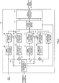
- Signal decoding apparatus 103 is mainly comprised of coded information operation section 601, decoding operation control section 602, base layer decoding section 603, first enhancement layer decoding section 604, second enhancement layer decoding section 605, control switches 606 and 607 and sampling frequency adjustment sections 608 and 609.
- Coded information operation section 601 demultiplexes the transmission mode information, base layer coded information, first enhancement layer coded information, second enhancement layer coded information and their respective transmission error detection bits included in received post-transmission coded information, and performs error detection for the base layer coded information, first enhancement layer coded information and second enhancement layer coded information according to predetermined procedures using the transmission error detection bits. Only when no error is detected in the respective information, coded information operation section 601 outputs the base layer coded information to base layer decoding section 603, outputs the first enhancement layer coded information to first enhancement layer decoding section 604 and outputs the second enhancement layer coded information to second enhancement layer decoding section 605. The error detecti.on procedures and transmission error detection method in coded information operation section 601 will be described later.
- codedinformationoperationsection 601 stores the table shown in FIG. 7 and outputs information indicating the transmission mode information and a pattern corresponding to the error detection result (hereinafter referred to as "pattern information"), to decoding operation control section 602.
- pattern information a pattern corresponding to the error detection result
- FIG.7 for each information, "1" is a case where error is detected, "0" is a case where no error is detected, and "-" is a case where no error detection processing is performed.
- coded information operation section 601 outputs pattern information "B" to decoding operation control section 602.
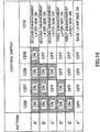
- Decoding operation control section 602 stores the table diagram shown in FIG.8 and performs ON/OFF control of switches 606 and 607 according to the pattern information output from coded information operation section 601. With regard to the operation of the control switch group, in FIG.8 , “ON” indicates control to "ON state” and “OFF” indicates control to "OFF state.”
- decoding operation control section 602 controls the sampling frequencies of output signals at sampling frequency adjustment sections 608 and 609.
- sampling frequencies in FIG. 8 , SR input is an input sampling frequency and SR enh1 is a first enhancement layer sampling frequency.
- Decoding operation control section 602 outputs information indicating the detection result (hereinafter referred to as "frame loss compensationinformation")to baselayerdecodingsection 603, first enhancement layer decoding section 604 and second enhancement layer decoding section 605.
- frame loss compensationinformation information indicating the detection result (hereinafter referred to as "frame loss compensationinformation"
- Base layer decoding section 603 decodes the base layer coded information output from coded information operation section 601 and generates a base layer decoded signal.
- the frame loss compensation information output from decoding operation control section 602 is "1, " error is detected in the base layer coded information.
- base layer decoding section 603 performs frame loss compensation processing and generates a base layer decoded signal. Then, base layer decoding section 603 outputs the base layer decoded signal to sampling frequency adjustment section 608.
- the internal configuration of base layer decoding section 603 will be described later.
- First enhancement layer decoding section 604 decodes the first enhancement layer coded information output from coded information operation section 601 and generates a first enhancement layer decoded signal. Furthermore, when the frame loss compensation information output from decoding operation control section 602 is "1," first enhancement layer decoding section 604 performs frame loss compensation processing and generates a first enhancement layer decoded signal. Then, first enhancement layer decoding section 604 outputs the first enhancement layer decoded signal to sampling frequency adjustment section 609. When the first enhancement layer coded information is not output from coded information operation section 601 and the frame loss compensation information for the first enhancement layer output from decoding operation control section 602 is "0," first enhancement layer decoding section 604 performs no operation.
- Second enhancement layer decoding section 605 decodes second enhancement layer coded information output from coded information operation section 601 and generates a second enhancement layer decoded signal. Furthermore, when the frame loss compensation information for the second enhancement layer output from decoding operation control section 602 is "1, " second enhancement layer decoding section 605 performs frame loss compensation processing and generates a second enhancement layer decoded signal. Then, second enhancement layer decoding section 605 outputs second enhancement layer decoded signal to control switch 607. When the second enhancement layer coded information is not output from coded information operation section 601 and the frame loss compensation information for the second enhancement layer output from decoding operation control section 602 is "0," second enhancement layer decoding section 605 performs no operation.
- Sampling frequency adjustment section 608 adjusts the sampling frequency of the base layer decoded signal output from base layer decoding section 603 based on control of decoding operation control section 602.
- Sampling frequency adjustment section 609 adjusts the sampling frequency of the first enhancement layer decoded signal output from first enhancement layer decoding section 604 based on control of decoding operation control section 602.
- addition section 610 adds the second enhancement layer decoded signal output from second enhancement layer decoding section 605 and the first enhancement layer decoded signal output from sampling frequency adjustment section 609, and outputs the signal after the addition to addition section 611. Furthermore, when control switch 607 is off and control switch 606 is on, addition section 610 outputs the first enhancement layer decoded signal output from sampling frequency adjustment section 609 to addition section 611. When control switches 606 and 607 are off, addition section 610 performs no operation.
- Addition section 611 adds the base layer decoded signal output from sampling frequency adjustment section 608 and the output signal of addition section 610, and outputs the signal after the addition as an output signal. Furthermore, when control switches 606 and 607 are off, addition section 611 outputs the base layer decoded signal output from sampling frequency adjustment section 608 as an output signal.
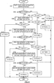
- coded information operation section 601 carries out error detection for the base layer coded information using the transmission error detection bits (S901) .
- coded information operation section 601 When error is detected as a result of S901 (S902: Yes), coded information operation section 601 outputs pattern information "I" when the transmission mode information is bitrate 3, pattern information "G” when the transmission mode information is bitrate 2, and pattern information "D” when the transmission mode information is bitrate 1, to decoding operation control section 602, and finishes the error detection processing (S903 to S907).
- coded information operation section 601 outputs the base layer coded information to base layer decoding section 603 (S908).
- coded information operation section 601 outputs pattern information "H” to decoding operation control section 602 and finishes the error detection processing (S910).
- coded information operation section 601 performs error detection for the first enhancement layer coded information using the transmission error detection bits (S911).
- coded information operation section 601 When error is detected as a result of S911 (S912: Yes), coded information operation section 601 outputs pattern information "F" when the transmission mode information is bitrate 2, and pattern information "C” when the transmission mode information is bitrate 1, to decoding operation control section 602, and finishes the error detection processing (S913 to S915).
- coded information operation section 601 outputs the first enhancement layer coded information to first enhancement layer decoding section 604 (S916) .
- coded information operation section 601 When thetransmission mode information is bitrate 2 (S917: Yes), coded information operation section 601 outputs pattern information "E" to decoding operation control section 602 and finishes the error detection processing (S918).
- coded information operation section 601 performs error detection for the second enhancement layer coded information using the transmission error detection bits (S919).
- coded information operation section 601 When error is detected as a result of S919 (S920: Yes), coded information operation section 601 outputs pattern information "B" to decoding operation control section 602 and finishes the error detection processing (S921).
- coded information operation section 601 outputs the second enhancement layer coded information to second enhancement layer decoding section 605 (S922), outputs pattern information "A" to decoding operation control section 602 and finishes the error detection processing (S923).
- Equation (6) CRC generating polynomial g crc (x) is expressed by Equation (6) below.
- g crc x 1 + x + x 4 + x 5 + x 9 + x 10
- Coded information operation section 601 calculates remainder R' (x) from Equation (7) below.
- Q(x) in Equation (7) is a quotient of division by g crc (x).
- CRC code CRC' [x] of ten bits for transmitted base layer coded information is determined using remainder R'(x) from Equation (8) below.
- coded information operation section 601 compares CRC'[x] with CRC code CRC[x] of transmission error detection bits added to the base layer coded information. When they match, coded information operation section 601 decides that there is no transmission error, and, when they do not match, coded into operation section 601 decides that there is transmission error.
- Coded information operation section 601 performs error detection using the same method for the first enhancement layer coded information and second enhancement layer coded information, in addition to base layer coded information.
- base layer decoding section 603 in FIG.6 will be explained using FIG.10 .
- base layer decoding section 603 performs CELP type speech decoding
- base layer coded information input to base layer decoding section 603 is demultiplexed into separate codes (L, A, G, F) by demultiplexing section 1001.
- Demultiplexed LPC code (L) is output to LPC decoding section 1002, and demultiplexed adaptive excitation code (A) is output to adaptive excitation codebook 1005.
- demultiplexed excitation gain code (G) is output to quantization gain generation section 1006, and demultiplexed fixed excitation code (F) is output to fixed excitation codebook 1007.
- LPC decoding section 1002 decodes the quantized LPC from code (L) output from demultiplexing section 1001 and outputs the result to synthesis filter 1003.
- Adaptive excitation codebook 1005 extracts samples over one frame from past excitation specified by code (A) output from demultiplexing section 1001 as adaptive excitation, and outputs them to multiplication section 1008.
- Quantization gain generation section 1006 decodes the quantization adaptive excitation gain and quantization fixed excitation gain specified by excitation gain code (G) output from demultiplexing section 1001 and outputs them to multiplication section 1008 and multiplication section 1009.
- G excitation gain code
- Fixed excitation codebook 1007 generates the fixed excitation specified by code (F) output from demultiplexing section 1001 and outputs the result to multiplication section 1009.
- Multiplication section 1008 multiplies the adaptive excitation by the quantization adaptive excitation gain and outputs the result to addition section 1010.
- Multiplication section 1009 multiplies the fixed excitation by the quantization fixed excitation gain and outputs the result to addition section 1010.
- Addition section 1010 adds the adaptive excitation and fixed excitation after gain multiplication output from multiplication sections 1008 and 1009, generates an excitation and outputs this to synthesis filter 1003 and adaptive excitation codebook 1005.
- Synthesis filter 1003 performs filter synthesis of the excitation output from addition section 1010 using filter coefficients decoded by LPC decoding section 1002 and outputs a synthesized signal to post-processing section 1004.
- Post-processing section 1004 applies processing for improving subjective quality of speech such as formant emphasis and pitch emphasis and processing for improving subjective quality of constant noise to the signal output from synthesis filter 1003, and outputs the result as base layer decoded information.
- Frame loss compensation control section 1011 receives as input base layer frame loss compensation information from decoding operation control section 602, and instructs adaptive excitation codebook 1005, quantization gain generation section 1006, fixed excitation codebook 1007, LPC decoding section 1002 and post-processing section 1004, to execute frame loss compensation processing, when the base layer frame loss compensation information "1."
- first enhancement layer decoding section 604 and second enhancement layer decoding section 605 in FIG. 6 are the same as the internal configuration of base layer decoding section 603 and have been explained above. Furthermore, the configuration of first enhancement layer decoding section 604 replaces the base layer coded information in FIG.10 with first enhancement layer coded information and replaces the base layer decoded signal in FIG.10 with a first enhancement layer decoded signal. Furthermore, the configuration of second enhancement layer decoding section 605 replaces the base layer coded information in FIG. 10 with second enhancement layer coded information and replaces the base layer decoded signal in FIG. 10 with a second enhancement layer decoded signal.
- coded information operation section 601 outputs base layer coded information to base layer decoding section 603, outputs a first enhancement layer decoded signal to first enhancement layer decoding section 604 and outputs a second enhancement layer decoded signal to second enhancement layer decoding section 605.
- control switches 606 and 607 are set to ON state, and the sampling frequencies of sampling frequency adjustment sections 608 and 609 are set to SR input , under control of decoding operation control section 602. Furthermore, decoding operation control section 602 substitutes "0" in all results frame loss compensation information and outputs them.
- base layer decoding section 603 performs decoding processing and outputs a base layer decoded signal
- first enhancement layer decoding section 604 performs decoding processing and outputs a first enhancement layer decoded signal
- second enhancement layer decoding section 605 performs decoding processing and outputs a second enhancement layer decoded signal.
- sampling frequency adjustment section 608 up-samples the base layer decoded signal and sets the sampling frequency at SR input
- sampling frequency adjustment section 609 up-samples the first enhancement layer decoded signal and sets the sampling frequency at SR input .
- a signal adding the base layer decoded signal, first enhancement layer decoded signal and second enhancement layer decoded signal is output as an output signal.
- coded information operation section 601 outputs base layer coded information to base layer decoding section 603 and outputs a first enhancement layer decoded signal to first enhancement layer decoding section 604. Coded information operation section 601 outputs nothing to second enhancement layer decoding section 605.
- control switch 606 is set in ON state and control switch 607 is set in OFF state and the sampling frequencies of sampling frequency adjustment sections 608 and 609 are set to SR input under control of decoding operation control section 602. Furthermore, decoding operation control section 602 substitutes "0" in all frame loss compensation information and outputs the results.
- base layer decoding section 603 performs decoding processing and outputs a base layer decoded signal
- first enhancement layer decoding section 604 performs decoding processing and outputs a first enhancement layer decoded signal
- Second enhancement layer decoding section 605 performs no operation.
- sampling frequency adjustment section 608 up-samples the base layer decoded signal and sets the sampling frequency to SR input and sampling frequency adjustment section 609 up-samples the first enhancement layer decoded signal and sets the sampling frequency to SR input .
- coded information operation section 601 outputs the base layer coded information to base layer decoding section 603. Coded information operation section 601 outputs nothing to first enhancement layer decoding section 604 and second enhancement layer decoding section 605.
- control switches 606 and 607 are set to OFF state, and the sampling frequency of sampling frequency adjustment section 608 is set to SR input under control of decoding operation control section 602. Furthermore, decoding operation control section 602 substitutes "0" in all frame loss compensation information and outputs the results.
- base layer decoding section 603 performs decoding processing and outputs a base layer decoded signal.
- First enhancement layer decoding section 604 and second enhancement layer decoding section 605 perform no operation.
- sampling frequency adjustment section 608 up-samples the base layer decoded signal and sets the sampling frequency to SR input .
- Sampling frequency adjustment section 609 performs no operation.
- the base layer decoded signal is output as an output signal.
- coded information operation section 601 outputs nothing to base layer decoding section 603, first enhancement layer decoding section 604 and second enhancement layer decoding section 605.
- control switches 606 and 607 are set to ON state and the sampling frequencies of sampling frequency adjustment sections 608 and 609 are set to SR input under control of decoding operation control section 602. Furthermore, decoding operation control section 602 substitutes "1" in all frame loss compensation information and outputs the results.
- base layer decoding section 603 performs frame loss compensation processing and outputs the base layer decoded signal.
- First enhancement layer decoding section 604 performs frame loss compensation processing and outputs a first enhancement layer decoded signal.
- Second enhancement layer decoding section 605 performs frame loss compensation processing and outputs a second enhancement layer decoded signal.
- sampling frequency adjustment section 608 up-samples the base layer decoded signal and sets the sampling frequency to SR input
- sampling frequency adjustment section 609 upsamples the first enhancement layer decoded signal and sets the sampling frequency to SR input .
- a signal adding the base layer decoded signal, first enhancement layer decoded signal and second enhancement layer decoded signal is output as an output signal.
- coded information operation section 601 outputs base layer coded information to base layer decoding section 603 and outputs a first enhancement layer decoded signal to first enhancement layer decoding section 604. Coded information operation section 601 outputs nothing to second enhancement layer decoding section 605.
- control switch 606 is set to ON state
- control switch 607 is set to OFF state
- the sampling frequencies of sampling frequency adjustment sections 608 and 609 are set to SR enh1 under control of decoding operation control section 602.
- decoding operation control section 602 substitutes "0" in all frame loss compensation information and outputs the results.
- base layer decoding section 603 performs decoding processing and outputs a base layer decoded signal.
- First enhancement layer decoding section 604 performs decoding processing and outputs a first enhancement layer decoded signal.
- Second enhancement layer decoding section 605 performs no operation.
- sampling frequency adjustment section 608 up-samples the base layer decoded signal and sets the sampling frequency to SR enh1 .
- Sampling frequency adjustment section 609 performs no operation.
- coded information operation section 601 outputs base layer coded information to base layer decoding section 603. Coded information operation section 601 outputs nothing to first enhancement layer decoding section 604 and second enhancement layer decoding section 605.
- control switches 606 and 607 are set to OFF state and the sampling frequency of sampling frequency adjustment section 608 is set to SR enh1 under control of decoding operation control section 602. Furthermore, decoding operation control section 602 substitutes "0" in all frame loss compensation information and outputs the results.
- base layer decoding section 603 performs decoding processing and outputs a base layer decoded signal.
- First enhancement layer decoding section 604 and second enhancement layer decoding section 605 perform no operation.
- sampling frequency adjustment section 608 up-samples the base layer decoded signal and sets the sampling frequency to SR enh1 .
- Sampling frequency adjustment section 609 performs no operation.
- the base layer decoded signal is output as an output signal.
- coded information operation section 601 outputs nothing to base layer decoding section 603, first enhancement layer decoding section 604 and second enhancement layer decoding section 605.
- control switch 606 is set to ON state
- control switch 607 is set to OFF state
- the sampling frequency of sampling frequency adjustment section 608 is set to SR enh1 , under control of decoding operation control section 602.
- decoding operation control section 602 substitutes "1" in the frame loss compensation information for the base layer and first enhancement layer and outputs the results, and substitutes "0" in the frame loss compensation information for the second enhancement layer and outputs the results.
- base layer decoding section 603 performs frame loss compensation processing and outputs a base layer decoded signal.
- First enhancement layer decoding section 604 performs frame loss compensation processing and outputs a first enhancement layer decoded signal.
- Second enhancement layer decoding section 605 performs no operation.
- sampling frequency adjustment section 608 up-samples the base layer decoded signal and sets the sampling frequency to SR enh1 .
- Sampling frequency adjustment section 609 performs no operation.
- coded information operation section 601 outputs base layer coded information to base layer decoding section 603. Coded information operation section 601 outputs nothing to first enhancement layer decoding section 604 and second enhancement layer decoding section 605.
- control switches 606 and 607 are set to OFF state under control of decoding operation control section 602. Furthermore, decoding operation control section 602 substitutes "0" in all frame loss compensation and outputs the results.
- base layer decoding section 603 performs decoding processing and outputs a base layer decoded signal.
- First enhancement layer decoding section 604 and second enhancement layer decoding section 605 perform no operation.
- sampling frequency adjustment sections 608 and 609 perform no operation.
- the base layer decoded signal is output as an output signal.
- coded information operation section 601 outputs nothing to base layer decoding section 603, first enhancement layer decoding section 604 and second enhancement layer decoding section 605.
- control switches 606 and 607 are set to OFF state under control of decoding operation control section 602. Furthermore, decoding operation control section 602 substitutes "1" in the frame loss compensation information for the base layer and outputs the result, and substitutes "0" in the frame loss compensation information for the first enhancement layer and second enhancement layer and outputs the results.
- base layer decoding section 603 performs frame loss compensation processing and outputs a base layer decoded signal.
- First enhancement layer decoding section 604 and second enhancement layer decoding section 605 perform no operation.
- sampling frequency adjustment sections 608 and 609 perform no operation.
- the base layer decoded signal is output as an output signal.
- this example adjusts the sampling frequencies of decoded signals of the first layer to the (i-1) th layer, adds the adjusted signals and outputs the result as an output signal. Furthermore, when error is detected in the base layer (pattern D, G, I), frame loss compensation processing is performed in all layers coded information is generated, the sampling frequency of each decoded signal obtained through this control is adjusted, and the adjusted signals are added and the result is output as an output signal.
- Signal coding apparatus 101 divides an input signal per N samples (N: natural number), and performs coding per frame, N samples being one frame.
- Signal coding apparatus 101 is mainly comprised of transmission bit rate control section 1101, control switches 1102 to 1105, down-sampling processing sections 1106 and 1110, base layer coding section 1107, base layer decoding section 1108, up-sampling processing sections 1109 and 1114, addition sections 1111 and 1115, first enhancement layer coding section 1112, first enhancement layer decoding section 1113, second enhancement layer coding section 1116, transmission error detection bit addition section 1117 and coded information integration section 1118.
- transmission mode information refers to information indicating the transmission bit rate when the input signal is coded and transmitted, and one of two or more predetermined transmission bit rates is selected as transmission mode information.
- Transmission mode information in this embodiment can take values of three types of predetermined transmission bit rates, namely, bitrate 1, bitrate 2 and bitrate 3 (bitrate 3 ⁇ bitrate 2 ⁇ bitrate 1).
- Transmission bit rate control section 1101 performs ON/OFF of control switches 1102 to 1105 according to the transmission mode information input. More specifically, when the transmission mode information is bitrate 1, transmission bit rate control section 1101 sets all control switches 1102 to 1105 to ON state. Furthermore, when transmission mode information is bitrate 2, transmission bit rate control section 1101 sets control switches 1102 and 1103 to ON state and sets control switches 1104 and 1105 to OFF state. Furthermore, when the transmission mode information is bitrate 3, transmission bit rate control section 1101 sets all control switches 1102 to 1105 to OFF state. Furthermore, transmission bit rate control section 1101 outputs transmission mode information to transmission error detection bit addition section 1117. In this way, transmission bit rate control section 1101 performs ON/OFF control of the control switches according to transmission mode information and thereby determines the combination of coding sections used for coding of input signals.
- the input signal is input to control switch 1102 and down-samplingprocessingsection1106.
- the sampling frequency of input signal will be referred to as "input sampling frequency.”
- Down-sampling processing section 1106 down-samples the input signal and outputs the signal to base layer coding section 1107.
- base layer sampling frequency the sampling frequency after down-sampling by down-sampling processing section 1106 will be referred to as "base layer sampling frequency.”
- Base layer coding section 1107 performs coding of the output signal of down-sampling processing section 1106 using a CELP type speech coding method, and outputs coded information obtained through the coding (hereinafter referred to as “base layer coded information") to transmission error detection bit addition section 1117 and control switch 1103.
- base layer decoding section 1108 When control switch 1103 is in ON state, base layer decoding section 1108 performs decoding of the base layer coded information output from base layer coding section 1107 using a CELP type speech decoding method and outputs the decoded signal obtained through the decoding (hereinafter referred to as "base layer decoded signal") to up-sampling processing section 1109. When control switch 103 is in OFF state, base layer decoding section 1108 performs no operation.
- up-sampling processing section 1109 When control switch 1103 is in ON state, up-sampling processing section 1109 up-samples the base layer decoded signal output from base layer decoding section 1108 and outputs the up-sampled signal to addition section 1111.
- first enhancement layer sampling frequency the up-sampled sampling frequency of up-sampling processing section 1109
- control switch 1103 When control switch 1103 is in OFF state, up-sampling processing section 1109 performs no operation.
- down-sampling processing section 1110 down-samples the input signal to the first enhancement layer sampling frequency and outputs the result to addition section 1111.
- addition section 1111 When control switches 1102 and 1103 are in ON state, addition section 1111 adds the signal obtained by inverting the polarity of the output signal of up-sampling processing section 1109 to the signal obtained from down-sampling processing section 1110, and outputs a first differential signal, which is the addition result, to first enhancement layer coding section 1112. When control switches 1102 and 1103 are in OFF state, addition section 1111 performs no operation.
- first enhancement layer coding section 1112 When control switches 1102 and 1103 are in ON state, first enhancement layer coding section 1112 performs coding of the output signal of addition section 1111 using a CELP type speech coding method and outputs the coded information obtained through the coding (hereinafter referred to as "first enhancement layer coded information") to control switch 1105 and transmission error detection bit addition section 1117. When control switches 1102 and 1103 are in OFF state, first enhancement layer coding section 1112 performs no operation.
- first enhancement layer decoding section 1113 When control switch 1105 is in ON state, first enhancement layer decoding section 1113 performs decoding of the first enhancement layer coded information output from first enhancement layer coding section 1112 using a CELP type speech decoding method and outputs the decoded signal obtained through the decoding (hereinafter referred to as "first enhancement layer decoded signal") to up-sampling processing section 1114.
- first enhancement layer decoding section 1113 When control switch 1105 is in ON state, first enhancement layer decoding section 1113 performs no operation.
- up-sampling processing section 1114 When control switch 1105 is in ON state, up-sampling processing section 1114 up-samples the first enhancement layer decoded signal output from first enhancement layer decoding s.ection 1113 to the input sampling frequency and outputs the up-sampled signal to addition section 1115. When control switch 1105 is in OFF state, up-sampling processing section 1114 performs no operation.
- addition section 1115 adds the signal obtained by inverting the polarity of the output signal of up-sampling processing section 1114 to the input signal, and outputs a second differential signal which is the addition result, to second enhancement layer coding section 1116.
- control switches 1104, 1105 are in OFF state, addition section 1115 performs no operation.
- second enhancement layer coding section 1116 When control switches 1104 and 1105 are in ON state, second enhancement layer coding section 1116 performs coding of the second differential signal output from addition section 1115 using a CELP type speech coding method, and outputs the coded information obtained through the coding (hereinafter referred to as "second enhancement layer coded information") to transmission error detection bit addition section 1117. When control switches 1104 and 1105 are in OFF state, second enhancement layer coding section 1116 performs no operation.
- Transmission error detection bit addition section 1117 receives as input the transmission mode information from transmission bit rate control section 1101, calculates transmission error detection bits using the transmission mode information, adds the transmission error detection bits to the transmission mode information and outputs the transmission mode information to coded information integration section 1118. Furthermore, transmission error detection bit addition section 1117 receives as input the base layer coded information from base layer coding section 1107, calculates transmission error detection bits using the base layer coded information, adds the transmission error detection bits to the base layer coded information and outputs the base layer coded information to coded information integration section 1118.
- transmission error detection bit addition section 1117 receives as input the first enhancement layer coded information from first enhancement layer coding section 1112, calculates transmission error detection bits using the first enhancement layer coded information, adds the transmission error detection bits to the first enhancement layer coded information and outputs the first enhanced layer coded information to coded information integration section 1118. Furthermore, when the transmission mode information is bitrate 1, transmission error detection bit addition section 1117 receives as input the second enhancement layer coded information from second enhancement layer coding section 1116, calculates transmission error detection bits using the second enhancement layer coded information, adds the transmission error detection bits to the second enhancement layer coded information and outputs the second enhanced layer coded information to coded information integration section 1118.
- Coded information integration section 1118 integrates the coded information and the transmission mode information output from transmission error detection bit addition section 1117, and outputs the result as pre-transmission coded information, to transmission path 102.
- base layer coding section 1107 in FIG.11 is the same as the internal configuration of base layer coding section 207 in FIG.2 , FIG.3 , and therefore explanations thereof will be omitted.
- base layer decoding section 1108 in FIG. 11 is the same as the internal configuration of base layer decoding section 208 in FIG. 2 , FIG.4 , and therefore explanations thereof will be omitted.
- First enhancement layer coding section 1112, first enhancement layer decoding section 1113, second enhancement layer coding section 1116 and transmission error detection bit addition section 1117 have also been described above, and therefore explanations thereof will be omitted.
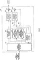
- Signal decoding apparatus 103 is mainly comprised of coded information operation section 1201, decoding operation control section 1202, base layer decoding section 1203, first enhancement layer decoding section 1204, second enhancement layer decoding section 1205, control switches 1206 to 1210 and sampling frequency adjustment sections 1211 and 1213.
- Coded information operation section 1201 demultiplexes the transmission mode information, base layer coded information, first enhancement layer coded information and second enhancement layer coded information, and their respective transmission error detection bits included in received coded information, and performs error detection for the base layer coded information, first enhancement layer coded information and second enhancement layer coded information according to predetermined procedures using the transmission error detection bits. Then, only when no error is detected in the respective information, coded information operation section 1201 outputs the base layer coded information to base layer decoding section 1203, outputs the first enhancement layer coded information to first enhancement layer decoding section 1204 and outputs the second enhancement layer coded information to second enhancement layer decoding section 1205. The error detection procedures and transmission error detection method in coded information operation section 1201 will be described later.
- codedinformationoperationsection 1201 stores the table shown in FIG.13 and outputs information indicating the transmission mode information and a pattern corresponding to the error detection result (hereinafter referred to as "pattern information"), to decoding operation control section 1202.
- pattern information a pattern corresponding to the error detection result
- FIG. 13 for each information, "1" is a case where error is detected, "0" is a case where no error is detected, and "-" is a case where no error detection processing is performed.
- transmission mode information is bitrate 1
- no error is detected in the base layer coded information and first enhancement layer coded information and errors is detected in the second enhancement layer coded information
- coded information operation section 1201 outputs pattern information "B" to decoding operation control section 1202.
- Decoding operation control section 1202 stores the table diagram shown in FIG.14 and performs ON/OFF control of control switches 1206 to 1210 according to the pattern information output from coded information operation section 1201.
- ON indicates . control to "ON state”
- OFF indicates control to "OFF state.”
- base layer side ON indicates connecting a switch to the base layer decoding section 1203 side
- first enhancement layer side ON indicates connecting a switch to the first enhancement layer decoding section 1204 side
- second enhancement layer side ON indicates connecting a switch to the second enhancement layer decoding section 1205 side.
- decoding operation control section 1202 detects whether or not to perform decoding processing (hereinafter referred to as "frame loss compensation processing") reusing codes used in earlier decoding (LPC code, adaptive excitation code, fixed excitation code, excitation gain code) according to the pattern information, and outputs information indicating the detection result to base layer decoding section 1203, first enhancement layer decoding section 1204 and second enhancement layer decoding section 1205.
- frame loss compensation processing reusing codes used in earlier decoding
- LPC code adaptive excitation code, fixed excitation code, excitation gain code
- Base layer decoding section 1203 decodes the base layer coded information output from coded information operation section 1201 and generates a base layer decoded signal.
- base layer decoding section 1203 performs frame loss compensation processing and generates a base layer decoded signal.
- Base layer decoding section 1203 outputs the base layer decoded signal to control switches 1206 and 1210. The internal configuration of base layer decoding section 1203 will be described later.
- First enhancement layer decoding section 1204 decodes the first enhancement layer coded information output from coded information operation section 1201 and generates a first enhancement layer decoded signal. Furthermore, when the frame loss compensation information output from decoding operation control section 1202 is "1," first enhancement layer decoding section 1204 performs frame loss compensation processing and generates a first enhancement layer decoded signal. Then, first enhancement layer decoding section 1204 outputs the first enhancement layer decoded signal to control switch 1207. When the first enhancement layer coded information is not output from coded information operation section 1201 and the frame loss compensation information for the first enhancement layer output from decoding operation control section 1202 is "0," first enhancement layer decoding section 1204 performs no operation.
- Second enhancement layer decoding section 1205 decodes the second enhancement layer coded information output from coded information operation section 1201 and generates a second enhancement layer decoded signal. Furthermore, when the frame loss compensation information for the second enhancement layer output from decoding operation control section 1202 is "1, " second enhancement layer decoding section 1205 performs frame loss compensation processing and generates a second enhancement layer decoded signal. Then, second enhancement layer decoding section 1205 outputs the second enhancement layer decoded signal to control switch 1209. When the second enhancement layer coded information is not output from coded information operation section 1201 and the frame loss compensation information of the second enhancement layer output from decoding operation control section 1202 is "0," second enhancement layer decoding section 1205 performs no operation.
- sampling frequency adjustment section 1211 When control switch 1206 is in ON state, sampling frequency adjustment section 1211 up-samples the sampling frequency of the base layer decoded signal output from base layer decoding section 1203 from the base layer sampling frequency to the first enhancement layer sampling frequency. Furthermore, when control switch 1206 is in OFF state, sampling frequency adjustment section 1211 performs no operation.
- sampling frequency adjustment section 1213 When control switch 1209 is in ON state, sampling frequency adjustment section 1213 up-samples the sampling frequency of the signal output from addition section 1212 from the first enhancement layer sampling frequency to the input sampling frequency. Furthermore, when control switch 1206 is in OFF state, sampling frequency adjustment section 1211 performs no operation.
- addition section 1212 When control switches 1206 and 1207 are in ON state, addition section 1212 adds the signal output from sampling frequency adjustment section 1211 and the first enhancement layer decoded signal output from first enhancement layer decoding section 1204 and outputs the signal after the addition to control switches 1208 and 1210. Furthermore, when control switch 1207 is in OFF state and at the same time control switch 1206 is in ON state, addition section 1212 outputs the signal output from sampling frequency adjustment section 1211 to control switches 1208 and 1210. When control switches 1206 and 1207 are in OFF state, addition section 1212 performs no operation.
- addition section 1214 When control switches 1208, 1209 are in ON state, addition section 1214 adds up the signal output from sampling frequency adjustment section 1213 and the second enhancement layer decoded signal output from second enhancement layer decoding section 1205 and outputs the signal after the addition to control switch 1210. Furthermore, when control switch 1209 is in OFF state and control switch 1208 is in ON state, addition section 1214 outputs the signal output from sampling frequency adjustment section 1213 to control switch 1210. When control switches 1208 and 1209 are in OFF state, addition section 1214 performs no operation.
- the error detection procedure of coded information operation section 1201 is the same as that of the flow chart in FIG.9 , and therefore explanations thereof will be omitted. Furthermore, the transmission error detection method at coded information operation section 1201 and the decoding method at base layer decoding section 1203, first enhancement layer decoding section 1204 and second enhancement layer decoding section 1205 are also the same as their respective methods in Example 1, and therefore explanations thereof will be omitted.
- coded information operation section 1201 outputs base layer coded information to base layer decoding section 1203, outputs a first enhancement layer decoded signal to first enhancement layer decoding section 1204 and outputs a second enhancement layer decoded signal to second enhancement layer decoding section 1205.
- control switches 1206, 1207, 1208 and 1209 are set in ON state under control of decoding operation control section 1202. Furthermore, decoding operation control section 1202 substitutes "0" in all frame loss compensation information and outputs the results.
- base layer decoding section 1203 performs decoding processing and outputs a base layer decoded signal.
- First enhancement layer decoding section 1204 performs decoding processing and outputs a first enhancement layer decoded signal.
- Second enhancement layer decoding section 1205 performs decoding processing and outputs a second enhancement layer decoded signal.
- sampling frequency adjustment section 1211 up-samples the base layer decoded signal and sets the sampling frequency to SR enh1
- sampling frequency adjustment section 1213 up-samples the signal obtained from addition section 1212 and sets the sampling frequency to SR input . Then, the signal output from addition section 1214 is output as an output signal.
- coded information operation section 1201 outputs base layer coded information to base layer decoding section 1203 and outputs a first enhancement layer decoded signal to first enhancement layer decoding section 1204. Coded information operation section 1201 outputs nothing to second enhancement layer decoding section 1205.
- control switches 1206, 1207 and 1208 are set in ON state and control switch 1209 is set in OFF state under control of decoding operation control section 1202. Furthermore, decoding operation control section 1202 substitutes "0" in all frame loss compensation information and outputs the results.
- base layer decoding section 1203 performs decoding processing, outputs a base layer decoded signal
- first enhancement layer decoding section 1204 performs decoding processing and outputs a first enhancement layer decoded signal
- Second enhancement layer decoding section 1205 performs no operation.
- sampling frequency adjustment section 1211 up-samples the base layer decoded signal and sets the sampling frequency to SR enh1
- sampling frequency adjustment section 1213 up-samples the signal obtained from addition section 1212 and sets the sampling frequency to SR input .
- the signal output from addition section 1214 is output as an output signal.
- coded information operation section 1201 outputs base layer coded information to base layer decoding section 1203. Coded information operation section 1201 outputs nothing to first enhancement layer decoding section 1204 and second enhancement layer decoding section 1205.
- control switches 1206 and 1208 are set in ON state and control switches 1207 and 1209 are set in OFF state under control of decoding operation control section 1202. Furthermore, decoding operation control section 1202 substitutes "0" in all frame loss compensation information and outputs the results.
- base layer decoding section 1203 performs decoding processing and outputs a base layer decoded signal.
- First enhancement layer decoding section 1204 and second enhancement layer decoding section 1205 performs no operation.
- sampling frequency adjustment section 1211 up-samples the base layer decoded signal and sets the sampling frequency to SR enh1
- sampling frequency adjustment section 1213 up-samples the signal obtained from addition section 1212 and sets the sampling frequency to SR input .
- the signal output from addition section 1214 is output as an output signal.
- coded information operation section 1201 outputs nothing to base layer decoding section 1203, first enhancement layer decoding section 1204 and second enhancement layer decoding section 1205. Furthermore, as shown in FIG.14 , control switches 1206, 1207, 1208 and 1209 are set in ON state under control of decoding operation control section 1202. Furthermore, decoding operation control section 1202 substitutes "1" in all frame loss compensation information and outputs the results.
- base layer decoding section 1203 performs frame loss compensation processing and outputs a base layer decoded signal.
- First enhancement layer decoding section 1204 performs frame loss compensation processing and outputs a first enhancement layer decoded signal.
- Second enhancement layer decoding section 1205 performs frame loss compensation processing and outputs a second enhancement layer decoded signal.
- sampling frequency adjustment section 1211 up-samples the base layer decoded signal and sets the sampling frequency to SR enh1
- sampling frequency adjustment section 1213 up-samples the signal obtained from addition section 1212 and sets the sampling frequency to SR input .
- the signal output from addition section 1214 is output as an output signal.
- coded information operation section 1201 outputs base layer coded information to base layer decoding section 1203 and outputs a first enhancement layer decoded signal to first enhancement layer decoding section 1204. Coded information operation section 1201 outputs nothing to second enhancement layer decoding section 1205.
- control switches 1206 and 1207 are set in ON state and control switches 1208 and 1209 are set in OFF state under the control of decoding operation control section 1202. Furthermore, decoding operation control section 1202 substitutes "0" in all loss compensation information and outputs the results.
- base layer decoding section 1203 performs decoding processing and outputs a base layer decoded signal
- first enhancement layer decoding section 1204 performs decoding processing and outputs a first enhancement layer decoded signal
- Second enhancement layer decoding section 1205 performs no operation.
- sampling frequency adjustment section 1211 up-samples the base layer decoded signal and sets the sampling frequency to SR enh1 .
- the signal obtained from addition section 1212 is output as an output signal.
- coded information operation section 1201 outputs base layer coded information to base layer decoding section 1203. Coded information operation section 1201 outputs nothing to first enhancement layer decoding section 1204 and second enhancement layer decoding section 1205.
- control switch 1206 is set in ON state and control switches 1207, 1208 and 1209 are set in OFF state under control of decoding operation control section 1202. Furthermore, decoding operation control section 1202 substitutes "0" in all frame loss compensation information and outputs the results.
- base layer decoding section 1203 performs decoding processing and outputs a base layer decoded signal.
- First enhancement layer decoding section 1204 and second enhancement layer decoding section 1205 perform no operation.
- sampling frequency adjustment section 1211 up-samples the base layer decoded signal and sets the sampling frequency to SR enh1 .
- the signal obtained from addition section 1212 is output as an output signal.
- coded information operation section 1201 outputs nothing to base layer decoding section 1203, first enhancement layer decoding section 1204 and second enhancement layer decoding section 1205. Furthermore, as shown in FIG.14 , control switches 1206 and 1207 are set in ON state and control switches 1208 and 1209 are set in OFF state under control of decoding operation control section 1202. Furthermore, decoding operation control section 1202 substitutes "1" in the frame loss compensation information for the base layer and first enhancement layer and outputs the results and substitutes "0" in the frame loss compensation information for the second enhancement layer and outputs the results.
- base layer decoding section 1203 performs frame loss compensation processing and outputs a base layer decoded signal
- first enhancement layer decoding section 1204 performs frame loss compensation processing and outputs a first enhancement layer decoded signal.
- Second enhancement layer decoding section 125 performs no operation.
- sampling frequency adjustment section 1211 up-samples the base layer decoded signal and sets the sampling frequency to SR enh1 .
- the signal obtained from addition section 1212 is output as an output signal.
- coded information operation section 1201 outputs base layer coded information to base layer decoding section 1203. Coded information operation section 1201 outputs nothing to first enhancement layer decoding section 1204 and second enhancement layer decoding section 1205.
- decoding operation control section 1202 substitutes "0" in all frame loss compensation information and outputs the results.
- base layer decoding section 1203 performs decoding processing and outputs a base layer decoded signal.
- First enhancement layer decoding section 1204 and second enhancement layer decoding section 1205 perform no operation.
- the base layer decoded signal is output as an output signal.
- coded information operation section 1201 outputs nothing to base layer decoding section 1203, first enhancement layer decoding section 1204 and second enhancement layer decoding section 1205.
- decoding operation control section 1202 substitutes "1" in the frame loss compensation information for the base layer and outputs the result, and substitutes "0" in the frame loss compensation information for the first enhancement layer and second enhancement layer and outputs the results.
- base layer decoding section 1203 performs frame loss compensation processing and outputs a base layer decoded signal.
- First enhancement layer decoding section 1204 and second enhancement layer decoding section 1205 perform no operation. Then, the base layer decoded signal is output as an output signal.
- this embodiment adjusts the sampling frequency of each decoded signal from the first layer to the (i-1) th layer and outputs the adjusted signal as an output signal. Furthermore, when error is detected in the base layer (pattern D, G, I), this embodiment performs frame loss compensation processing for all layers in which coded information is generated, adjusts the sampling frequency of each decoded signal obtained through this control and outputs the adjusted signal as an output signal.
- the signal decoding apparatus is not limited to decoding of coded information utilizing transmission errors occurring during transmission, and is equally applicable to cases where the number of layers to be transmitted at a relay station is reduced according to the situation channels are used (utilization rate or the like).
- the relay station updates transmission mode information and coded information after the reduction and adds the original transmission mode information (pre-adjustment transmission mode information) to the redundant part of the coded information.
- the coded information operation section of the signal decoding apparatus detects whether the coded information includes pre-adjustment transmission mode information, and, when pre-adjustment transmission mode information is included, decoding operation is performed according to the result of a comparison between the pre-adjustment transmission mode information and the transmission mode information.
- Coded information operation section 1201 stores the table shown in FIG.15 and outputs information indicating patterns corresponding to the transmission mode information and pre-adjustment transmission mode information (hereinafter referred to as "pattern information") to decoding'operation control section 1202.
- Decoding operation control section 1202 stores the table shown in FIG.16 and performs ON/OFF control of switches 1206 to 1210 according to pattern information output from coded information operation section 1001.
- the processing of the base layer decoding section, first enhancement layer decoding section, second enhancement layer decoding section, sampling frequency adjustment section or the like is the same as that described above. However, the frame loss compensation processing will not be considered here.
- the present invention is not intended to limit layers and is applicable to cases where a residual signal, which is a difference between an input signal and output signal in a lower layer, is coded in an upper layer using layered signal coding/decoding method involving plurality of layers.
- the above described example and embodiment have explained the case where a CRC code is used as the transmission error detection bit, but the present invention does not place limits on codes to detect or correct transmission errors. Furthermore, a plurality of transmission error detection bits may be used such as calculating a convolutional code after calculating a CRC code.
- the transmission mode information is extremely important information for a scalable coding/decoding scheme, and therefore it is desirable to add codes having not only the transmission error detection function but also error correction function.
- the present invention is also applicable to a case where the configuration shown in FIG. 6 of Example 1 or FIG. 12 of Embodiment 1 is recorded, written into a machine-readable recording medium such as memory, disk, tape, CD, DVD and then operated.
- a machine-readable recording medium such as memory, disk, tape, CD, DVD
- FIG. 17 is a block diagram showing the configurations of a signal transmission apparatus and a signal reception apparatus including the signal coding apparatus and the signal decoding apparatus explained in above described Example 1 and Embodiment 1. A case where speech signals are transmitted and received will be explained using FIG.17 below.
- a speech signal is converted to an electric signal by input apparatus 1701 and output to A/D conversion apparatus 1702.
- A/D conversion apparatus 1702 converts the (analog) signal output from input apparatus 1701 to a digital signal and outputs the digital signal to speech coding apparatus 1703.
- Speech coding apparatus 1703 is provided with signal coding apparatus 101 shown in FIG.1 , performs coding of the digital speech signal output from A/D conversion apparatus 1702 and outputs the coded information to RF modulation apparatus 1704.
- RF modulation apparatus 1704 converts the coded information output from speech coding apparatus 1703 to a signal to be transmitted on a propagation medium such as radio wave and outputs the signal to transmission antenna 1705.
- Transmission antenna 1705 transmits the output signal output from RF modulation apparatus 1704 as a radio wave (RF signal).
- RF signal 1706 in the figure represent the radio wave (RF signal) transmitted from transmission antenna 1705.
- RF signal 1707 is received by reception antenna 1708 and output to RF demodulation apparatus 1709.
- RF signal 1707 in the figure represent a radio wave received by reception antenna 1708, which is totally the same as RF signal 1706 unless there are signal attenuation and superimposition of noise over the propagation path.
- RF demodulation apparatus 1709 demodulates the coded information from the RF signal output from reception antenna 1708 and outputs the result to speech decoding apparatus 1710.
- Speech decoding apparatus 1710 is provided with signal decoding apparatus 103 shown in FIG. 1 , decodes the speech signal from the voice coded information output from RF demodulation apparatus 1709 and outputs a digital decoded speech signal obtained to D/A conversion apparatus 1711.
- D/A conversion apparatus 1711 converts the digital speech signal output from speech decoding apparatus 1710 to an analog electric signal and outputs the analog electric signal to output apparatus 1712.
- Output apparatus 1712 converts the electric signal to air vibration and outputs the vibration in a manner that is audible to human ears as a sound wave.
- the present invention is suitable for use in a signal decoding apparatus used in the fields of a packet communication system represented by Internet communication, non-packet communication system, mobile communication system, car navigation system or the like.
Landscapes
- Engineering & Computer Science (AREA)
- Signal Processing (AREA)
- Computational Linguistics (AREA)
- Health & Medical Sciences (AREA)
- Audiology, Speech & Language Pathology (AREA)
- Human Computer Interaction (AREA)
- Physics & Mathematics (AREA)
- Acoustics & Sound (AREA)
- Multimedia (AREA)
- Compression, Expansion, Code Conversion, And Decoders (AREA)
Claims (3)
- Signaldecodierungsvorrichtung mit einem Codierte-Informationen-Betriebsabschnitt (1201), einem Decodierbetriebs-Steuerabschnitt (1202), einem Basisschicht-Decodierabschnitt (1203), einem Erste-Erweiterungsschicht-Decodierabschnitt (1204), einem Zweite-Erweiterungsschicht-Decodierabschnitt (1205), Steuerschaltern 1206 bis 1210 und Abtast-frequenz-Einstellabschnitten 1211 und 1213, wobei:der Codierte-Informationen-Betriebsabschnitt (1201) konfiguriert ist, um Sendemodusinformationen, codierte Basisschicht-Informationen, codierte Erste-Erweiterungsschicht-Informationen und codierte Zweite-Erweiterungsschicht-Informationen sowie entsprechende Sendefehler-Erfassungsbits in den empfangenen codierten Informationen zu demultiplexen, und konfiguriert ist, um eine Fehlererfassung für die codierten Basisschicht-Informationen, die codierten Erste-Erweiterungsschicht-Informationen und die codierten Zweite-Erweiterungsschicht-Informationen in Übereinstimmung mit vorbestimmten Prozeduren unter Verwendung der Sendefehler-Erfassungsbits durchzuführen, wobei nur dann, wenn kein Fehler in den entsprechenden Informationen erfasst wird, der Codierte-Informationen-Betriebsabschnitt (1201) konfiguriert ist, um die codierten Basisschicht-Informationen an den Basisschicht-Decodierabschnitt (1203) auszugeben, konfiguriert ist, um die codierten Erste-Erweiterungsschicht-Informationen an den Erste-Erweiterungsschicht-Decodierabschnitt (1204) auszugeben, und konfiguriert ist, um die codierten Zweite-Erweiterungsschicht-Informationen an den Zweite-Erweiterungsschicht-Decodierabschnitt (1205) auszugeben,der Codierte-Informationen-Betriebsabschnitt (1201) konfiguriert ist, um eine erste Tabelle zu speichern:
Muster Sendemodus-informationen (Bitrate) Sendefehlerinformationen Basisschicht erste Erweiterungsschicht zweite Erweiterungsschicht A 1 0 0 0 B 1 0 0 1 C 1 0 1 - D 1 1 - - E 2 0 0 F 2 0 1 G 2 1 - H 3 0 I 3 1 und konfiguriert ist, um Informationen, die die Sendemodusinformationen und Musterinformationen in Entsprechung zu dem Fehlererfassungsergebnis angeben, an den Decodierbetriebs-Steuerabschnitt (1202) auszugeben, wobei in der ersten Tabelle für jede der Informationen "1" dafür steht, dass ein Fehler erfasst wird, "0" dafür steht, dass kein Fehler erfasst wird und "-" dafür steht, dass keine Fehlererfassungsverarbeitung durchgeführt wird,der Decodierbetriebs-Steuerabschnitt (1202) konfiguriert ist, um eine zweite Tabelle zu speichern:
 und konfiguriert ist, um eine EIN/AUS-Steuerung der Steuerschalter 1206 bis 1210 gemäß den aus dem Codierte-Informationen-Betriebsabschnitt (1201) ausgegebenen Musterinformationen durchzuführen,wobei, in der zweiten Tabelle, in Bezug auf die Operationen der Steuerschaltergruppe "EIN" eine Steuerung zum "EIN-Zustand" angibt und "AUS" eine Steuerung zum "AUS-Zustand" angibt und in Bezug auf den Steuerschalter 1210 "Basisschicht-Seite EIN" eine Verbindung eines Schalters mit der Seite des Basisschicht-Decodierabschnitts (1203) angibt, "Erste-Erweiterungsschicht-Seite EIN" eine Verbindung eines Schalters mit der Seite des Erste-Erweiterungsschicht-Decodierabschnitts (1204) angibt und "Zweite-Erweiterungsschicht-Seite EIN" eine Verbindung eines Schalters mit der Seite des Zweite-Erweiterungsschicht-Decodierabschnitts (1205) angibt,wobei der Decodierbetriebs-Steuerabschnitt (1202) konfiguriert ist, um zu erfassen, ob eine Rahmenverlust-Kompensationsverarbeitung unter Wiederverwendung von in einer früheren Decodierung verwendeten Codes in Übereinstimmung mit den Musterinformationen durchgeführt werden soll oder nicht, und konfiguriert ist, um Informationen, die das Erfassungsergebnis angeben, an den Basisschicht-Decodierabschnitt (1203), den Erste-Erweiterungsschicht-Decodierabschnitt (1204) und den Zweite-Erweiterungsschicht-Decodierabschnitt (1205) auszugeben, wobei, in der zweiten Tabelle, wenn der Wert der Rahmenverlust-Kompensationsinformationen "0" ist, der entsprechende Decodierabschnitt konfiguriert ist, um keine Rahmenverlust-Kompensationsverarbeitung durchzuführen, und wenn der Wert "1" ist, der entsprechende Decodierabschnitt konfiguriert ist, um eine Rahmenverlust-Kompensationsverarbeitung durchzuführen,der Basisschicht-Decodierabschnitt (1203) konfiguriert ist, um die codierten Basisschichtinformationen, die aus dem Codierte-Informationen-Betriebsabschnitt (1201) ausgegeben werden, zu decodieren, und konfiguriert ist, um ein decodiertes Basisschicht-Signal zu erzeugen, wobei, wenn die aus dem Decodierbetriebs-Steuerabschnitt (1202) ausgegebenen Rahmenverlust-Kompensationsinformationen "1" sind, weil ein Fehler in den codierten Basisschichtinformationen erfasst wird und die codierten Basisschichtinformationen nicht aus dem Codierte-Informationen-Betriebsabschnitt (1201) ausgegeben werden, der Basisschicht-Decodierabschnitt (1203) konfiguriert ist, um eine Rahmenverlust-Kompensationsverarbeitung durchzuführen, und konfiguriert ist, um ein decodiertes Basisschicht-Signal zu erzeugen, und der Basisschicht-Decodierabschnitt (1203) konfiguriert ist, um das decodierte Basisschicht-Signal an die Steuerschalter 1206 und 1210 auszugeben,der Erste-Erweiterungsschicht-Decodierabschnitt (1204) konfiguriert ist, um die codierten Erste-Erweiterungsschicht-Informationen, die aus dem Codierte-Informationen-Betriebsabschnitt (1201) ausgegeben werden, zu decodieren, und konfiguriert ist, um ein decodiertes Erste-Erweiterungsschicht-Signal zu erzeugen, wobei, wenn die Rahmenverlust-Kompensationsinformationen, die aus dem Decodierbetriebs-Steuerabschnitt (1202) ausgegeben werden, "1" sind, der Erste-Erweiterungsschicht-Decodierabschnitt (1204) konfiguriert ist, um eine Rahmenverlust-Kompensationsverarbeitung durchzuführen, und konfiguriert ist, um ein decodiertes Erste-Erweiterungsschicht-Signal zu erzeugen, und der Erste-Erweiterungsschicht-Decodierabschnitt (1204) konfiguriert ist, um das decodierte Erste-Erweiterungsschicht-Signal an den Steuerschalter 1207 auszugeben, und wobei, wenn die codierten Erste-Erweiterungsschicht-Informationen nicht von dem Codierte-Informationen-Betriebsabschnitt (1201) ausgegeben werden und die Rahmenverlust-Kompensationsinformationen für die erste Erweiterungsschicht, die aus dem Decodierbetriebs-Steuerabschnitt (1202) ausgegeben werden, "0" sind, der Erste-Erweiterungsschicht-Decodierabschnitt (1204) konfiguriert ist, um keine Operation durchzuführen,der Zweite-Erweiterungsschicht-Decodierabschnitt (1205) konfiguriert ist, um die codierten Zweite-Erweiterungsschicht-Informationen, die aus dem Codierte-Informationen-Betriebsabschnitt (1201) ausgegeben werden, zu decodieren, und konfiguriert ist, um ein decodiertes Zweite-Erweiterungsschicht-Signal zu erzeugen, wobei, wenn die Rahmenverlust-Kompensationsinformationen für die zweite Erweiterungsschicht, die aus dem Decodierbetriebs-Steuerabschnitt (1202) ausgegeben werden, "1" sind, der Zweite-Erweiterungsschicht-Decodierabschnitt (1205) konfiguriert ist, um eine Rahmenverlust-Kompensationsverarbeitung durchzuführen, und konfiguriert ist, um ein decodiertes Zweite-Erweiterungsschicht-Signal zu erzeugen, und der Zweite-Erweiterungsschicht-Decodierabschnitt (1205) konfiguriert ist, um das decodierte Zweite-Erweiterungsschicht-Signal an den Steuerschalter 1209 auszugeben, und wenn die codierten Zweite-Erweiterungsschicht-Informationen nicht aus dem Codierte-Informationen-Betriebsabschnitt (1201) ausgegeben werden und die Rahmenverlust-Kompensationsinformationen der zweiten Erweiterungsschicht, die aus dem Decodierbetriebs-Steuerabschnitt (1202) ausgegeben werden, "0" sind, der Zweite-Erweiterungsschicht-Decodierabschnitt (1205) konfiguriert ist, um keine Operation durchzuführen,wenn sich der Steuerschalter 1206 im EIN-Zustand befindet, der Abtastfrequenz-Einstellabschnitt 1211 konfiguriert ist, um die Abtastfrequenz des decodierten Basisschicht-Signals, das aus dem Basisschicht-Decodierabschnitt (1203) ausgegeben wird, von der Basisschicht-Abtastfrequenz zu der Erste-Erweiterungsschicht-Abtastfrequenz zu erhöhen, und wenn sich der Steuerschalter 1206 im AUS-Zustand befindet, der Abtastfrequenz-Einstellabschnitt 1211 konfiguriert ist, um keine Operation durchzuführen,wenn sich der Steuerschalter 1208 im EIN-Zustand befindet, der Abtastfrequenz-Einstellabschnitt 1213 konfiguriert ist, um die Abtastfrequenz des von einem Additionsabschnitt 1212 ausgegebenen Signals von der Erste-Erweiterungsschicht-Abtastfrequenz zu der Eingangsabtastfrequenz zu erhöhen, und wenn sich der Steuerschalter 1208 im AUS-Zustand befindet, der Abtastfrequenz-Einstellabschnitt 1213 konfiguriert ist, um keine Operation durchzuführen,wenn sich die Steuerschalter 1206 und 1207 im EIN-Zustand befinden, der Additionsabschnitt 1212 konfiguriert ist, um das Signal, das von dem Abtastfrequenz-Einstellabschnitt 1211 ausgegeben wird, und das decodierte Erste-Erweiterungsschicht-Signal, das von dem Erste-Erweiterungsschicht-Decodierabschnitt (1204) ausgegeben wird, zu addieren, und konfiguriert ist, um das Signal nach der Addition an die Steuerschalter 1208 und 1210 auszugeben, und wenn sich der Steuerschalter 1207 im AUS-Zustand befindet und sich gleichzeitig der Steuerschalter 1206 im EIN-Zustand befindet, der Additionsabschnitt 1212 konfiguriert ist, um das von dem Abtastfrequenz-Einstellabschnitt 1211 ausgegebene Signal an die Steuerschalter 1208 und 1210 auszugeben, und wenn sich die Steuerschalter 1206 und 1207 im AUS-Zustand befinden, der Additionsabschnitt 1212 konfiguriert ist, um keine Operation durchzuführen, undwenn sich die Steuerschalter 1208 und 1209 im EIN-Zustand befinden, der Additionsabschnitt 1214 konfiguriert ist, um das Signal, das von dem Abtastfrequenz-Einstellabschnitt 1213 ausgegeben wird, und das decodierte Zweite-Erweiterungsschicht-Signal, das von dem Zweite-Erweiterungsschicht-Decodierabschnitt (1205) ausgegeben wird, zu addieren, und konfiguriert ist, um das Signal nach der Addition an den Steuerschalter 1210 auszugeben, und wenn sich der Steuerschalter 1209 im AUS-Zustand befindet und sich der Steuerschalter 1208 im EIN-Zustand befindet, der Additionsabschnitt 1214 konfiguriert ist, um das von dem Abtastfrequenz-Einstellabschnitt 1213 ausgegebene Signal an den Steuerschalter 1210 auszugeben, und wenn sich die Steuerschalter 1208 und 1209 im AUS-Zustand befinden, der Additionsabschnitt 1214 konfiguriert ist, um keine Operation durchzuführen.
 - Signaldecodierungsverfahren, das umfasst:die folgenden Schritte, die durch einen Codierte-Informationen-Betriebsabschnitt (1201) durchgeführt werden:Demultiplexen von Sendemodusinformationen, codierten Basisschicht-Informationen, codierten Erste-Erweiterungsschicht-Informationen und codierten Zweite-Erweiterungsschicht-Informationen sowie entsprechenden Sendefehler-Erfassungsbits in den empfangenen codierten Informationen, undDurchführen einer Fehlererfassung für die codierten Basisschicht-Informationen, die codierten Erste-Erweiterungsschicht-Informationen und die codierten Zweite-Erweiterungsschicht-Informationen in Übereinstimmung mit vorbestimmten Prozeduren unter Verwendung der Sendefehler-Erfassungsbits, wobei nur dann, wenn kein Fehler in den entsprechenden Informationen erfasst wird, die folgenden Schritte durch den Codierte-Informationen-Betriebsabschnitt (1201) durchgeführt werden:Ausgeben der codierten Basisschicht-Informationen an den Basisschicht-Decodierabschnitt (1203),Ausgeben der codierten Erste-Erweiterungsschicht-Informationen an den Erste-Erweiterungsschicht-Decodierabschnitt (1204),Ausgeben der codierten Zweite-Erweiterungsschicht-Informationen an den Zweite-Erweiterungsschicht-Decodierabschnitt (1205),wobei das Verfahren weiterhin die folgenden Schritte umfasst, die durch den Codierte-Informationen-Betriebsabschnitt (1201) durchgeführt werden:Speichern einer ersten Tabelle:
Muster Sendemodusinformationen (Bitrate) Sendefehlerinformationen Basisschicht erste Erweiterungsschicht zweite Erweiterungsschicht A 1 0 0 0 B 1 0 0 1 C 1 0 1 - D 1 1 - - E 2 0 0 F 2 0 1 G 2 1 - H 3 0 I 3 1 Ausgeben von Informationen, die die Sendemodusinformationen und Musterinformationen in Entsprechung zu dem Fehlererfassungsergebnis angeben, an den Decodierbetriebs-Steuerabschnitt (1202), wobei in der ersten Tabelle für jede der Informationen "1" dafür steht, dass ein Fehler erfasst wird, "0" dafür steht, dass kein Fehler erfasst wird und "-" dafür steht, dass keine Fehlererfassungsverarbeitung durchgeführt wird,wobei das Verfahren weiterhin die folgenden Schritte umfasst, die durch den Decodierbetriebs-Steuerabschnitt (1202) durchgeführt werden:Speichern einer zweiten Tabelle: , und
, und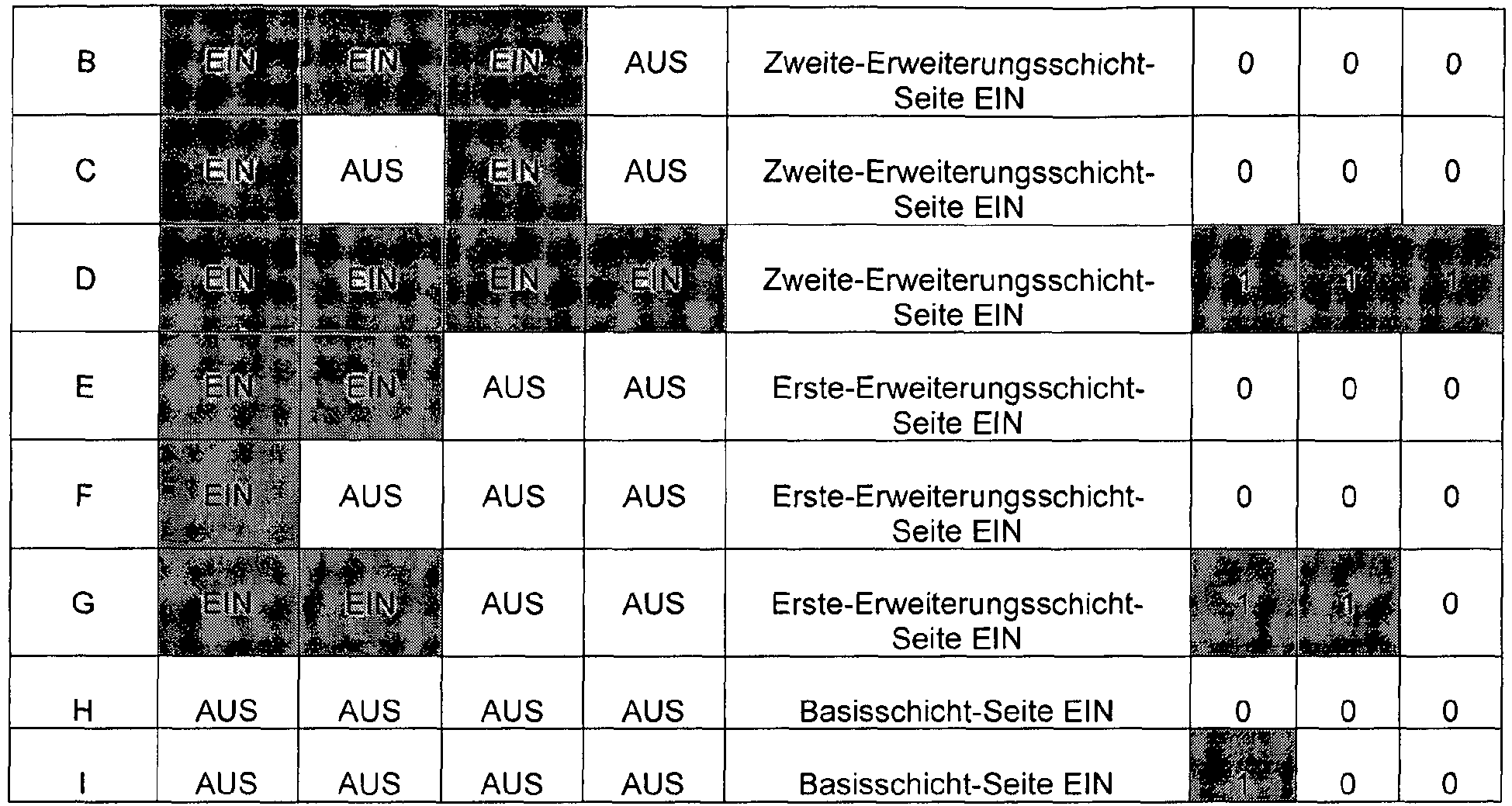 Durchführen einer EIN/AUS-Steuerung der Steuerschalter 1206 bis 1210 gemäß den aus dem Codierte-Informationen-Betriebsabschnitt (1201) ausgegebenen Musterinformationen, wobei, in der zweiten Tabelle, in Bezug auf die Operationen der Steuerschaltergruppe "EIN" eine Steuerung zum "EIN-Zustand" angibt und "AUS" eine Steuerung zum "AUS-Zustand" angibt und in Bezug auf den Steuerschalter 1210 "Basisschicht-Seite EIN" eine Verbindung eines Schalters mit der Seite des Basis-schicht-Decodierabschnitts (1203) angibt, "Erste-Erweiterungsschicht-Seite EIN" eine Verbindung eines Schalters mit der Seite des Erste-Erweiterungsschicht-Decodierabschnitts (1204) angibt und "Zweite-Erweiterungsschicht-Seite EIN" eine Verbindung eines Schalters mit der Seite des Zweite-Erweiterungsschicht-Decodierabschnitts (1205) angibt,Erfassen, ob eine Rahmenverlust-Kompensationsverarbeitung unter Wiederverwendung von in einer früheren Decodierung verwendeten Codes in Übereinstimmung mit den Musterinformationen durchgeführt werden soll oder nicht, undAusgeben von Informationen, die das Erfassungsergebnis angeben, an den Basisschicht-Decodierabschnitt (1203), den Erste-Erweiterungsschicht-Decodierabschnitt (1204) und den Zweite-Erweiterungsschicht-Decodierabschnitt (1205), wobei, in der zweiten Tabelle, wenn der Wert der Rahmenverlust-Kompensationsinformationen "0" ist, der entsprechende Decodierabschnitt keine Rahmenverlust-Kompensationsverarbeitung durchführt, und wenn der Wert "1" ist, der entsprechende Decodierabschnitt eine Rahmenverlust-Kompensationsverarbeitung durchführt,wobei das Verfahren weiterhin die folgenden Schritte umfasst, die durch den Basisschicht-Decodierabschnitt (1203) durchgeführt werden:Decodieren der codierten Basisschichtinformationen, die aus dem Codierte-Informationen-Betriebsabschnitt (1201) ausgegeben werden, und Erzeugen eines decodierten Basisschicht-Signals, undwenn die aus dem Decodierbetriebs-Steuerabschnitt (1202) ausgegebenen Rahmenverlust-Kompensationsinformationen "1" sind, weil ein Fehler in den codierten Basisschichtinformationen erfasst wird und die codierten Basisschichtinformationen nicht aus dem Codierte-Informationen-Betriebsabschnitt (1201) ausgegeben werden, Durchführen einer Rahmenverlust-Kompensationsverarbeitung, Erzeugen eines decodierten Basisschicht-Signals und Ausgeben des decodierten Basisschicht-Signals an die Steuerschalter 1206 und 1210,wobei das Verfahren weiterhin die folgenden Schritte umfasst, die durch den Erste-Erweiterungsschicht-Decodierabschnitt (1204) durchgeführt werden:Decodieren der codierten Erste-Erweiterungsschicht-Informationen, die aus dem Codierte-Informationen-Betriebsabschnitt (1201) ausgegeben werden, und Erzeugen eines decodierten Erste-Erweiterungsschicht-Signals, undwenn die Rahmenverlust-Kompensationsinformationen, die aus dem Decodierbetriebs-Steuerabschnitt (1202) ausgegeben werden, "1" sind, Durchführen einer Rahmenverlust-Kompensationsverarbeitung, Erzeugen eines decodierten Erste-Erweiterungsschicht-Signals und Ausgeben des decodierten Erste-Erweiterungsschicht-Signals an den Steuerschalter 1207, undwenn die codierten Erste-Erweiterungsschicht-Informationen nicht von dem Codierte-Informationen-Betriebsabschnitt (1201) ausgegeben werden und die Rahmenverlust-Kompensationsinformationen für die erste Erweiterungsschicht, die aus dem Decodierbetriebs-Steuerabschnitt (1202) ausgegeben werden, "0" sind, Durchführen keiner Operation,wobei das Verfahren weiterhin die folgenden Schritte umfasst, die durch den Zweite-Erweiterungsschicht-Decodierabschnitt (1205) durchgeführt werden:Decodieren der codierten Zweite-Erweiterungsschicht-Informationen, die aus dem Codierte-Informationen-Betriebsabschnitt (1201) ausgegeben werden, und Erzeugen eines decodierten Zweite-Erweiterungsschicht-Signals, undwenn die Rahmenverlust-Kompensationsinformationen für die zweite Erweiterungsschicht, die aus dem Decodierbetriebs-Steuerabschnitt (1202) ausgegeben werden, "1" sind, Durchführen einer Rahmenverlust-Kompensationsverarbeitung, Erzeugen eines decodierten Zweite-Erweiterungsschicht-Signals und Ausgeben des decodierten Zweite-Erweiterungsschicht-Signals an den Steuerschalter 1209, undwenn die codierten Zweite-Erweiterungsschicht-Informationen nicht aus dem Codierte-Informationen-Betriebsabschnitt (1201) ausgegeben werden und die Rahmenverlust-Kompensationsinformationen der zweiten Erweiterungsschicht, die aus dem Decodierbetriebs-Steuerabschnitt (1202) ausgegeben werden, "0" sind, Durchführen keiner Operation,wobei das Verfahren weiterhin die folgenden Schritte umfasst, die durch den Abtastfrequenz-Einstellabschnitt 1211 durchgeführt werden:wenn sich der Steuerschalter 1206 im EIN-Zustand befindet, Erhöhen der Abtastfrequenz des decodierten Basisschicht-Signals, das aus dem Basisschicht-Decodierabschnitt (1203) ausgegeben wird, von der Basisschicht-Abtastfrequenz zu der Erste-Erweiterungsschicht-Abtastfrequenz, undwenn sich der Steuerschalter 1206 im AUS-Zustand befindet, Durchführen keiner Operation,wobei das Verfahren weiterhin die folgenden Schritte umfasst, die durch den Abtastfrequenz-Einstellabschnitt 1213 durchgeführt werden:wenn sich der Steuerschalter 1208 im EIN-Zustand befindet, Erhöhen der Abtastfrequenz des von einem Additionsabschnitt 1212 ausgegebenen Signals von der Erste-Erweiterungsschicht-Abtastfrequenz zu der Eingangsabtastfrequenz, undwenn sich der Steuerschalter 1208 im AUS-Zustand befindet, Durchführen keiner Operation,wobei das Verfahren weiterhin die folgenden Schritte umfasst, die durch den Additionsabschnitt 1212 durchgeführt werden:wenn sich die Steuerschalter 1206 und 1207 im EIN-Zustand befinden, Addieren des Signals, das von dem Abtastfrequenz-Einstellabschnitt 1211 ausgegeben wird, und des decodierten Erste-Erweiterungsschicht-Signals, das von dem Erste-Erweiterungsschicht-Decodierabschnitt (1204) ausgegeben wird, und Ausgeben des Signals nach der Addition an die Steuerschalter 1208 und 1210, undwenn sich der Steuerschalter 1207 im AUS-Zustand befindet und sich gleichzeitig der Steuerschalter 1206 im EIN-Zustand befindet, Ausgeben des von dem Abtastfrequenz-Einstellabschnitt 1211 ausgegebenen Signals an die Steuerschalter 1208 und 1210, undwenn sich die Steuerschalter 1206 und 1207 im AUS-Zustand befinden, Durchführen keiner Operation,wobei das Verfahren weiterhin die folgenden Schritte umfasst, die durch den Additionsabschnitt 1214 durchgeführt werden:wenn sich die Steuerschalter 1208 und 1209 im EIN-Zustand befinden, Addieren des Signals, das von dem Abtastfrequenz-Einstellabschnitt 1213 ausgegeben wird, und des decodierten Zweite-Erweiterungsschicht-Signals, das von dem Zweite-Erweiterungsschicht-Decodierabschnitt (1205) ausgegeben wird, und Ausgeben des Signals nach der Addition an den Steuerschalter 1210, undwenn sich der Steuerschalter 1209 im AUS-Zustand befindet und sich der Steuerschalter 1208 im EIN-Zustand befindet, Ausgeben des von dem Abtastfrequenz-Einstellabschnitt 1213 ausgegebenen Signals an den Steuerschalter 1210, undwenn sich die Steuerschalter 1208 und 1209 im AUS-Zustand befinden, Durchführen keiner Operation.
 - Programm, das bei einer Ausführung auf einem Computer die Schritte des Decodierverfahrens von Anspruch 2 implementiert.
Applications Claiming Priority (3)
| Application Number | Priority Date | Filing Date | Title |
|---|---|---|---|
| JP2004003402 | 2004-01-08 | ||
| JP2004224240A JP4733939B2 (ja) | 2004-01-08 | 2004-07-30 | 信号復号化装置及び信号復号化方法 |
| PCT/JP2004/019016 WO2005066937A1 (ja) | 2004-01-08 | 2004-12-20 | 信号復号化装置及び信号復号化方法 |
Publications (3)
| Publication Number | Publication Date |
|---|---|
| EP1699043A1 EP1699043A1 (de) | 2006-09-06 |
| EP1699043A4 EP1699043A4 (de) | 2008-04-16 |
| EP1699043B1 true EP1699043B1 (de) | 2015-02-11 |
Family
ID=34752092
Family Applications (1)
| Application Number | Title | Priority Date | Filing Date |
|---|---|---|---|
| EP04807373.8A Expired - Lifetime EP1699043B1 (de) | 2004-01-08 | 2004-12-20 | Signaldecodierungsverfahren und signaldecodierungsvorrichtung |
Country Status (7)
| Country | Link |
|---|---|
| US (2) | US7411522B2 (de) |
| EP (1) | EP1699043B1 (de) |
| JP (1) | JP4733939B2 (de) |
| KR (1) | KR20060135699A (de) |
| CN (1) | CN1898723B (de) |
| CA (1) | CA2552853A1 (de) |
| WO (1) | WO2005066937A1 (de) |
Families Citing this family (23)
| Publication number | Priority date | Publication date | Assignee | Title |
|---|---|---|---|---|
| CA2575215A1 (en) * | 2004-07-28 | 2006-02-02 | Matsushita Electric Industrial Co., Ltd. | Relay device and signal decoding device |
| CN102592604A (zh) * | 2005-01-14 | 2012-07-18 | 松下电器产业株式会社 | 可扩展性解码装置及可扩展性解码方法 |
| US7970602B2 (en) | 2005-02-24 | 2011-06-28 | Panasonic Corporation | Data reproduction device |
| US7725799B2 (en) * | 2005-03-31 | 2010-05-25 | Qualcomm Incorporated | Power savings in hierarchically coded modulation |
| KR100738077B1 (ko) | 2005-09-28 | 2007-07-12 | 삼성전자주식회사 | 계층적 오디오 부호화 및 복호화 장치와 방법 |
| EP1933304A4 (de) * | 2005-10-14 | 2011-03-16 | Panasonic Corp | Skalierbare kodierungsanordnung, skalierbare dekodierungsanordnung und verfahren dazu |
| FR2897977A1 (fr) * | 2006-02-28 | 2007-08-31 | France Telecom | Procede de limitation de gain d'excitation adaptative dans un decodeur audio |
| JP5173795B2 (ja) * | 2006-03-17 | 2013-04-03 | パナソニック株式会社 | スケーラブル符号化装置およびスケーラブル符号化方法 |
| EP1841072B1 (de) | 2006-03-30 | 2016-06-01 | Unify GmbH & Co. KG | Verfahren und Einrichtung zum Dekodieren von schichtkodierten Daten |
| US20090248407A1 (en) * | 2006-03-31 | 2009-10-01 | Panasonic Corporation | Sound encoder, sound decoder, and their methods |
| JP4551472B2 (ja) * | 2006-05-25 | 2010-09-29 | パイオニア株式会社 | デジタル音声データ処理装置及び処理方法 |
| US20080059154A1 (en) * | 2006-09-01 | 2008-03-06 | Nokia Corporation | Encoding an audio signal |
| KR100912826B1 (ko) * | 2007-08-16 | 2009-08-18 | 한국전자통신연구원 | G.711 코덱의 음질 향상을 위한 향상 계층 부호화 및복호화 장치와 그 방법 |
| CN100550712C (zh) | 2007-11-05 | 2009-10-14 | 华为技术有限公司 | 一种信号处理方法和处理装置 |
| CN101207665B (zh) | 2007-11-05 | 2010-12-08 | 华为技术有限公司 | 一种衰减因子的获取方法 |
| JP5269195B2 (ja) * | 2009-05-29 | 2013-08-21 | 日本電信電話株式会社 | 符号化装置、復号装置、符号化方法、復号方法及びそのプログラム |
| WO2013105709A1 (ko) * | 2012-01-10 | 2013-07-18 | 조선대학교산학협력단 | 확장형 오류검출코드 기반의 오류 검출 장치 및 그 오류 검출 장치를 포함하는 자가검사 프로그래머블 연산 유닛 |
| US9357211B2 (en) * | 2012-12-28 | 2016-05-31 | Qualcomm Incorporated | Device and method for scalable and multiview/3D coding of video information |
| KR102244612B1 (ko) | 2014-04-21 | 2021-04-26 | 삼성전자주식회사 | 무선 통신 시스템에서 음성 데이터를 송신 및 수신하기 위한 장치 및 방법 |
| KR102538975B1 (ko) * | 2017-07-20 | 2023-06-02 | 소니그룹주식회사 | 송신 장치, 송신 방법, 수신 장치 및 수신 방법 |
| US10530523B2 (en) | 2017-11-20 | 2020-01-07 | International Business Machines Corporation | Dynamically adjustable cyclic redundancy code rates |
| US10541782B2 (en) * | 2017-11-20 | 2020-01-21 | International Business Machines Corporation | Use of a cyclic redundancy code multiple-input shift register to provide early warning and fail detection |
| US10530396B2 (en) | 2017-11-20 | 2020-01-07 | International Business Machines Corporation | Dynamically adjustable cyclic redundancy code types |
Family Cites Families (16)
| Publication number | Priority date | Publication date | Assignee | Title |
|---|---|---|---|---|
| US31182A (en) * | 1861-01-22 | Wood-bending machine | ||
| US5703652A (en) | 1995-07-28 | 1997-12-30 | Sony Corporation | Information signal encoding system and method for adaptively encoding an information signal |
| JP3629826B2 (ja) * | 1995-07-28 | 2005-03-16 | ソニー株式会社 | 情報信号符号化装置、符号化方法、並びに情報信号復号方法 |
| US5825313A (en) | 1995-08-01 | 1998-10-20 | Sony Corporation | Information signal encoding apparatus, encoding method thereof, information signal decoding method, and information signal record medium thereof |
| JP3496402B2 (ja) * | 1995-08-01 | 2004-02-09 | ソニー株式会社 | 情報信号符号化装置、符号化方法、並びに情報信号復号方法 |
| JPH10233692A (ja) * | 1997-01-16 | 1998-09-02 | Sony Corp | オーディオ信号符号化装置および符号化方法並びにオーディオ信号復号装置および復号方法 |
| JP3134817B2 (ja) * | 1997-07-11 | 2001-02-13 | 日本電気株式会社 | 音声符号化復号装置 |
| JPH11130997A (ja) | 1997-10-28 | 1999-05-18 | Mitsubishi Chemical Corp | 記録液 |
| US7272556B1 (en) * | 1998-09-23 | 2007-09-18 | Lucent Technologies Inc. | Scalable and embedded codec for speech and audio signals |
| JP2000352999A (ja) | 1999-06-11 | 2000-12-19 | Nec Corp | 音声切替装置 |
| JP3559488B2 (ja) * | 2000-02-16 | 2004-09-02 | 日本電信電話株式会社 | 音響信号の階層符号化方法及び復号化方法 |
| JP4545980B2 (ja) | 2000-05-11 | 2010-09-15 | キヤノン株式会社 | 符号化装置及び符号化方法並びに記憶媒体 |
| US6757860B2 (en) | 2000-08-25 | 2004-06-29 | Agere Systems Inc. | Channel error protection implementable across network layers in a communication system |
| JP2003241799A (ja) * | 2002-02-15 | 2003-08-29 | Nippon Telegr & Teleph Corp <Ntt> | 音響符号化方法、復号化方法、符号化装置、復号化装置及び符号化プログラム、復号化プログラム |
| US7599835B2 (en) * | 2002-03-08 | 2009-10-06 | Nippon Telegraph And Telephone Corporation | Digital signal encoding method, decoding method, encoding device, decoding device, digital signal encoding program, and decoding program |
| WO2004097796A1 (ja) * | 2003-04-30 | 2004-11-11 | Matsushita Electric Industrial Co., Ltd. | 音声符号化装置、音声復号化装置及びこれらの方法 |
-
2004
- 2004-07-30 JP JP2004224240A patent/JP4733939B2/ja not_active Expired - Fee Related
- 2004-12-20 US US10/585,313 patent/US7411522B2/en not_active Expired - Lifetime
- 2004-12-20 EP EP04807373.8A patent/EP1699043B1/de not_active Expired - Lifetime
- 2004-12-20 CA CA002552853A patent/CA2552853A1/en not_active Abandoned
- 2004-12-20 KR KR1020067013795A patent/KR20060135699A/ko not_active Withdrawn
- 2004-12-20 WO PCT/JP2004/019016 patent/WO2005066937A1/ja not_active Ceased
- 2004-12-20 CN CN2004800390384A patent/CN1898723B/zh not_active Expired - Fee Related
-
2008
- 2008-07-09 US US12/170,232 patent/US7636055B2/en not_active Expired - Lifetime
Also Published As
| Publication number | Publication date |
|---|---|
| US20070277078A1 (en) | 2007-11-29 |
| JP2005222014A (ja) | 2005-08-18 |
| CA2552853A1 (en) | 2005-07-21 |
| JP4733939B2 (ja) | 2011-07-27 |
| CN1898723B (zh) | 2011-03-09 |
| US20080297380A1 (en) | 2008-12-04 |
| EP1699043A4 (de) | 2008-04-16 |
| KR20060135699A (ko) | 2006-12-29 |
| EP1699043A1 (de) | 2006-09-06 |
| CN1898723A (zh) | 2007-01-17 |
| US7411522B2 (en) | 2008-08-12 |
| US7636055B2 (en) | 2009-12-22 |
| WO2005066937A1 (ja) | 2005-07-21 |
Similar Documents
| Publication | Publication Date | Title |
|---|---|---|
| US7636055B2 (en) | Signal decoding apparatus and signal decoding method | |
| CA2177422C (en) | Voice/unvoiced classification of speech for use in speech decoding during frame erasures | |
| US8010348B2 (en) | Adaptive encoding and decoding with forward linear prediction | |
| JP4218134B2 (ja) | 復号装置及び方法、並びにプログラム提供媒体 | |
| EP2382627B1 (de) | Selektive skalierungsmaskenberechnung auf der basis von spitzendetektion | |
| JPH0430200A (ja) | 音声復号化方法 | |
| CN101138174A (zh) | 可扩展解码装置和可扩展解码方法 | |
| JP4958780B2 (ja) | 符号化装置、復号化装置及びこれらの方法 | |
| JP2010213350A (ja) | 中継装置 | |
| JP4550176B2 (ja) | 音声符号化方法 | |
| JP3888097B2 (ja) | ピッチ周期探索範囲設定装置、ピッチ周期探索装置、復号化適応音源ベクトル生成装置、音声符号化装置、音声復号化装置、音声信号送信装置、音声信号受信装置、移動局装置、及び基地局装置 | |
| JP4373693B2 (ja) | 音響信号の階層符号化方法および階層復号化方法 | |
| KR100718487B1 (ko) | 디지털 음성 코더들에서의 고조파 잡음 가중 | |
| JP3006790B2 (ja) | 音声符号化復号化方法及びその装置 | |
| JP3063087B2 (ja) | 音声符号化復号化装置及び音声符号化装置ならびに音声復号化装置 | |
| JP2008139447A (ja) | 音声符号化装置及び音声復号装置 | |
| JP3350340B2 (ja) | 音声符号化方法および音声復号化方法 | |
| JPH0284700A (ja) | 音声符号化復号化装置 | |
| CN103119650A (zh) | 编码装置和编码方法 | |
| JPH034300A (ja) | 音声符号化復号化方式 | |
| JPH11316600A (ja) | ラグパラメ―タの符号化方法及びその装置並びに符号帳作成方法 |
Legal Events
| Date | Code | Title | Description |
|---|---|---|---|
| PUAI | Public reference made under article 153(3) epc to a published international application that has entered the european phase |
Free format text: ORIGINAL CODE: 0009012 |
|
| 17P | Request for examination filed |
Effective date: 20060630 |
|
| AK | Designated contracting states |
Kind code of ref document: A1 Designated state(s): DE FR GB IT |
|
| DAX | Request for extension of the european patent (deleted) | ||
| RBV | Designated contracting states (corrected) |
Designated state(s): DE FR GB IT |
|
| A4 | Supplementary search report drawn up and despatched |
Effective date: 20080318 |
|
| RAP1 | Party data changed (applicant data changed or rights of an application transferred) |
Owner name: PANASONIC CORPORATION |
|
| 17Q | First examination report despatched |
Effective date: 20110520 |
|
| REG | Reference to a national code |
Ref country code: DE Ref legal event code: R079 Ref document number: 602004046612 Country of ref document: DE Free format text: PREVIOUS MAIN CLASS: G10L0019120000 Ipc: G10L0019005000 |
|
| RAP1 | Party data changed (applicant data changed or rights of an application transferred) |
Owner name: PANASONIC INTELLECTUAL PROPERTY CORPORATION OF AME |
|
| GRAP | Despatch of communication of intention to grant a patent |
Free format text: ORIGINAL CODE: EPIDOSNIGR1 |
|
| RIC1 | Information provided on ipc code assigned before grant |
Ipc: G11B 20/24 20060101ALI20140709BHEP Ipc: G10L 19/005 20130101AFI20140709BHEP Ipc: G11B 20/18 20060101ALI20140709BHEP |
|
| INTG | Intention to grant announced |
Effective date: 20140729 |
|
| RIN1 | Information on inventor provided before grant (corrected) |
Inventor name: MORII, TOSHIYUKI Inventor name: YAMANASHI, TOMOFUMI Inventor name: SATO, KAORU |
|
| GRAS | Grant fee paid |
Free format text: ORIGINAL CODE: EPIDOSNIGR3 |
|
| GRAA | (expected) grant |
Free format text: ORIGINAL CODE: 0009210 |
|
| AK | Designated contracting states |
Kind code of ref document: B1 Designated state(s): DE FR GB IT |
|
| REG | Reference to a national code |
Ref country code: GB Ref legal event code: FG4D |
|
| REG | Reference to a national code |
Ref country code: DE Ref legal event code: R081 Ref document number: 602004046612 Country of ref document: DE Owner name: III HOLDINGS 12, LLC, WILMINGTON, US Free format text: FORMER OWNER: MATSUSHITA ELECTRIC INDUSTRIAL CO., LTD., KADOMA-SHI, OSAKA, JP |
|
| REG | Reference to a national code |
Ref country code: DE Ref legal event code: R096 Ref document number: 602004046612 Country of ref document: DE Effective date: 20150326 |
|
| REG | Reference to a national code |
Ref country code: DE Ref legal event code: R097 Ref document number: 602004046612 Country of ref document: DE |
|
| PLBE | No opposition filed within time limit |
Free format text: ORIGINAL CODE: 0009261 |
|
| STAA | Information on the status of an ep patent application or granted ep patent |
Free format text: STATUS: NO OPPOSITION FILED WITHIN TIME LIMIT |
|
| PG25 | Lapsed in a contracting state [announced via postgrant information from national office to epo] |
Ref country code: IT Free format text: LAPSE BECAUSE OF FAILURE TO SUBMIT A TRANSLATION OF THE DESCRIPTION OR TO PAY THE FEE WITHIN THE PRESCRIBED TIME-LIMIT Effective date: 20150211 |
|
| 26N | No opposition filed |
Effective date: 20151112 |
|
| GBPC | Gb: european patent ceased through non-payment of renewal fee |
Effective date: 20151220 |
|
| REG | Reference to a national code |
Ref country code: FR Ref legal event code: ST Effective date: 20160831 |
|
| PG25 | Lapsed in a contracting state [announced via postgrant information from national office to epo] |
Ref country code: GB Free format text: LAPSE BECAUSE OF NON-PAYMENT OF DUE FEES Effective date: 20151220 |
|
| PG25 | Lapsed in a contracting state [announced via postgrant information from national office to epo] |
Ref country code: FR Free format text: LAPSE BECAUSE OF NON-PAYMENT OF DUE FEES Effective date: 20151231 |
|
| REG | Reference to a national code |
Ref country code: DE Ref legal event code: R082 Ref document number: 602004046612 Country of ref document: DE Representative=s name: GRUENECKER PATENT- UND RECHTSANWAELTE PARTG MB, DE Ref country code: DE Ref legal event code: R081 Ref document number: 602004046612 Country of ref document: DE Owner name: III HOLDINGS 12, LLC, WILMINGTON, US Free format text: FORMER OWNER: PANASONIC INTELLECTUAL PROPERTY CORP. OF AMERICA, TORRANCE, CALIF., US |
|
| PGFP | Annual fee paid to national office [announced via postgrant information from national office to epo] |
Ref country code: DE Payment date: 20211228 Year of fee payment: 18 |
|
| REG | Reference to a national code |
Ref country code: DE Ref legal event code: R119 Ref document number: 602004046612 Country of ref document: DE |
|
| PG25 | Lapsed in a contracting state [announced via postgrant information from national office to epo] |
Ref country code: DE Free format text: LAPSE BECAUSE OF NON-PAYMENT OF DUE FEES Effective date: 20230701 |