EP1699014A2 - Bildgebende anordnung volumetrischer Computertomographie - Google Patents
Bildgebende anordnung volumetrischer Computertomographie Download PDFInfo
- Publication number
- EP1699014A2 EP1699014A2 EP05018698A EP05018698A EP1699014A2 EP 1699014 A2 EP1699014 A2 EP 1699014A2 EP 05018698 A EP05018698 A EP 05018698A EP 05018698 A EP05018698 A EP 05018698A EP 1699014 A2 EP1699014 A2 EP 1699014A2
- Authority
- EP
- European Patent Office
- Prior art keywords
- projection data
- image
- data
- projection
- physiologic
- Prior art date
- Legal status (The legal status is an assumption and is not a legal conclusion. Google has not performed a legal analysis and makes no representation as to the accuracy of the status listed.)
- Withdrawn
Links
Images





Classifications
-
- G—PHYSICS
- G06—COMPUTING OR CALCULATING; COUNTING
- G06T—IMAGE DATA PROCESSING OR GENERATION, IN GENERAL
- G06T12/00—Tomographic reconstruction from projections
- G06T12/10—Image preprocessing, e.g. calibration, positioning of sources or scatter correction
-
- A—HUMAN NECESSITIES
- A61—MEDICAL OR VETERINARY SCIENCE; HYGIENE
- A61B—DIAGNOSIS; SURGERY; IDENTIFICATION
- A61B6/00—Apparatus or devices for radiation diagnosis; Apparatus or devices for radiation diagnosis combined with radiation therapy equipment
- A61B6/02—Arrangements for diagnosis sequentially in different planes; Stereoscopic radiation diagnosis
- A61B6/027—Arrangements for diagnosis sequentially in different planes; Stereoscopic radiation diagnosis characterised by the use of a particular data acquisition trajectory, e.g. helical or spiral
-
- G—PHYSICS
- G06—COMPUTING OR CALCULATING; COUNTING
- G06T—IMAGE DATA PROCESSING OR GENERATION, IN GENERAL
- G06T2211/00—Image generation
- G06T2211/40—Computed tomography
- G06T2211/412—Dynamic
Definitions
- the present invention is generally directed to a method of imaging. More specifically, the present invention is directed to the generation of images from angularly disconnected computed tomography projection data sets. The present invention is also directed to the correction of artifacts arising in cardiac imaging.
- a halfscan technique based on a weighted fan-beam ramp-filtering algorithm with connected projection data has been discussed [1].
- the projection data in this technique are connected over an angular range of ⁇ +2 ⁇ m , wherein ⁇ represents a half rotation and ⁇ m represents the half of the fan angle.
- This technique uses weighting to compensate for redundant data samples prior to using ramp-filtering and fan-beam backprojection. However, it fails to allow one to use disconnected projection data.
- a weighted fan-beam algorithm based on the Hilbert transform (1) and a weighted parallel-beam ramp-filtering algorithm (2) have also been considered [3]. These algorithms filter data by using the kernel of the Hilbert transform for (1) and by using the kernel of the ramp-filter for (2), weight the filtered data to compensate for redundancy of samples, and backproject the weighted filtered data to obtain images.
- the applicability of these algorithms to reconstruct images from disconnected projection data is subject to major constraints. Specifically, only an algorithm that is not based on ramp-filtering may be used when either a fan-beam or a cone-beam is used. And after applying either a fan-to-parallel beam or a cone-to-fan parallel-beam re-binning technique, only parallel-beam reconstruction may be used.
- Equation 8 in Reference [4] shows cone-beam to parallel-beam re-binning (sorting)
- FIG. 1 in Reference [4] shows re-binned parallel-beam data
- Equation 20 of Reference [4] and Equation 5 of Reference [5] show that the algorithm uses cyclic angles over 180° (and not 360°). It is natural in the context of these references, which use parallel-beam data, to develop algorithms based on 180° cyclic angular range.
- Taiko data by interpolation has been discussed [7,8].
- the generated Taiko data is used to fill in missing data after which standard reconstruction techniques may be used.
- the Taiko approach of References [7,8] does not, however, discuss a weighting scheme.
- the Taiko approach requires considerable computational processing power, which is a major disadvantage.
- the above-mentioned algorithms therefore do not allow one to (1) use data which is not parallel but divergent in the xy plane; (2) use a filtered backprojection algorithm based on ramp-filtering; and (3) use disconnected projection data.
- the above-mentioned algorithms are also characterized with several other problems. These problems are now further discussed.
- FIGS. 1A-1F illustrate several configurations of patches.
- FIG. 1A illustrates 180° patches.
- FIG. 1B illustrates connected 90° patches.
- FIG. 1C illustrates one 180° patch flanked on the other side by a 120° patch.
- FIG. 1D illustrates a case wherein the number of patches is three and each patches are separated by 60° in projection angle. This provides the smallest patch size and the best temporal resolution (1/6 of one rotation, Trot). However, if the patches are separated by 120°, the patch size with the known algorithms is 120° and the temporal resolution is Trot/3, twice as large as the best case. This is illustrated in FIG. 1E. Further, if there is a patch in the opposite side, such as the red patch of FIG. 1C, one has to either (1) discard it which leads to larger image noise or (2) expand the patch to connect it to another patch which may degrade the temporal resolution.
- FIG. 1F illustrates three disconnected 60° patches, which is the difficult situation the present invention will address.
- cardiac imaging is that conventional techniques do not allow one to smooth the transition from one heart cycle to another. Moreover, since the lack of smoothness associated with heart cycle transitions is associated with banding artifacts, conventional techniques often yield cardiac imaging artifacts.
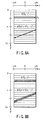
- FIGS. 2A-2C illustrate examples of artifacts.
- FIG. 2A illustrates artifacts (indicated by the arrows (a),(b)) in an image obtained using fan-beam computed tomography.
- FIG. 2B illustrates artifacts (indicated by the arrows (a)) in an image obtained using cone-beam computed tomography.
- FIG. 2C illustrates a nearly artifact-free image obtained using cone-beam computed tomography in conjunction with the present invention.
- FIGS. 3A and 3B illustrate one of the reasons explaining the presence of artifacts in cardiac imaging.
- FIG. 3A illustrates a helical orbit wherein projection data is obtained for a cardiac phase of interest (i.e., within a certain cardiac or time window).
- FIG. 3B illustrates the cardiac phase of interest.
- the segments (A), (B), (C) represent the same phase for which projection data are obtained to reconstruct images or volume as represented by the disjoint segments (A), (B), (C) in FIG. 3A.
- the original scanning orbit is continuous (such as a helix)
- the effective or valid segments (patches) of the orbit are not continuous.
- this situation is unavoidable in helical cardiac imaging given the dynamic nature of the heart.
- FIGS. 4A and 4B illustrate ideas facilitating an understanding of previously proposed algorithms.
- FIG. 4A relates to a single-cycle method (SCM).
- FIG. 4B relates to multi-cycle method (MCM).
- SCM uses projection data from one cardiac cycle (or heart beat) to reconstruct one slice (or one slab of the volume) in stacked fan-beam geometry [10,11,12].
- the algorithm first interpolates data simultaneously obtained along the z-axis.
- the algorithm then applies a time window weighting function over a certain period of time (e.g., a halfscan) and reconstructs images with a fan-beam algorithm based on ramp filtering.
- SCM can be extended to a cone-beam algorithm, wherein it reduces to a simple, helical Feldkamp halfscan upon adjusting the time center to the gating point (see the time-shifting technique in References [10,11]). Specifically, the gating center is first found, a halfscan weighting is then applied to the projection data centering the gating point, and, lastly, filtered cone-beam backprojection is used.
- SCM uses one heart cycle (or, more precisely, one cardiac time window or one "patch") to reconstruct one slice or slab of volume.
- the red heart cycle is used to reconstruct the red slab on the z-axis using about half a rotation; and the blue heart cycle (with a different half a rotation angle) is used to reconstruct the blue slab on the z-axis.
- References [10,11,12] describe SCM algorithms for fan-beam or stacked fan-beam.
- Reference [13] uses SCM with a fan-to-parallel re-binning technique.
- MCM uses projection data from more than one cardiac cycle to reconstruct one slice by using a narrower time window.
- the red and blue patches are used to reconstruct the lower slab (displayed in red and blue around the z-axis); and the blue and green cycles are used to reconstruct the upper slab (displayed in blue and green around the z-axis).
- the MCM algorithm has been discussed in the context of stacked fan-beam geometry [14], cone-beam geometry [2], and fan-to-parallel re-binning based parallel-beam geometry [15,16,17].
- References [4,5,18] use MCM with a cone-to-parallel fan-beam re-binning technique and discuss an illumination window having a feathering feature at both the beginning and the end of the window.
- this so-called overscan weight has been known for many years (see, e.g., Reference [21]) to compensate for redundant samples.
- Embodiments of the present invention addressing the artifact problem have nothing to do with the redundancy weighting.
- the trapezoid function used in References [4,5] must have a breaking point at a period of ⁇ in ⁇ (the parallel projection angle). Such a restriction constitutes a major disadvantage and can prevent the desired smoothing.
- the above-mentioned algorithms therefore do not allow one to smooth the transition from one heart cycle to another and thus to prevent banding artifacts that occur in cardiac imaging.
- the above-mentioned algorithms have several other problems. These problems are now further discussed.
- the present invention provides a method, system, and computer program product for reconstructing an image, comprising: (1) obtaining projection data using an X-ray detector and one of a cone-beam X-ray generator and a fan-beam X-ray generator; (2) weighting the projection data to compensate for redundant projection data; (3) filtering the weighted data using a ramp-based filtering function to generate filtered projection data; and (4) reconstructing the image by back-projecting the filtered projection data along a radial path.
- the present invention provides a method, system, and computer program product for reconstructing an image, comprising: (1) obtaining projection data using a multi-row X-ray detector and one of a cone-beam X-ray generator and a fan-beam X-ray generator, wherein the projection data are obtained using a helical trajectory; (2) obtaining a physiologic signal having a first physiologic cycle and a second physiologic cycle; (3) determining, based on the obtained projection data and the obtained physiologic signal, first projection data corresponding to the first physiologic cycle and second projection data corresponding to the second physiologic cycle; (4) weighting the first projection data and the second projection data so that a contribution of the first projection data and the second projection data changes gradually along a rotational axis of the helical trajectory; and (5) reconstructing the image from the weighted first projection data and the weighted second projection data.
- the present invention provides a method, system, and computer program product for reconstructing an image, comprising: (1) obtaining projection data using an X-ray detector and one of a cone-beam X-ray generator and a fan-beam X-ray generator; (2) weighting the obtained projection data to compensate for redundant projection data; (3) filtering the weighted projection data using a ramp-based filtering function to generate filtered projection data; (4) reconstructing the image by back-projecting the filtered projection data along a radial path.
- the present invention provides a method, system, and computer program product for reconstructing an image, comprising: (1) obtaining projection data using a multi-row X-ray detector and one of a cone-beam X-ray generator and a fan-beam X-ray generator, wherein the projection data are obtained using a helical trajectory; (2) obtaining a physiologic signal having a first physiologic cycle and a second physiologic cycle; (3) determining, based on the obtained projection data and the obtained physiologic signal, first projection data corresponding to the first physiologic cycle and second projection data corresponding to the second physiologic cycle; (4) reconstructing first image data and second image data from the first projection data and the second projection data, respectively; (5) weighting the first image data and the second image data so that a contribution of the first image data and the second image data changes gradually along a rotational axis of the helical trajectory; and (6) combining the weighted first image data and the weighted second image data to reconstruct
- the present invention provides a method, system, and computer program product for reconstructing an image, comprising: (1) obtaining a plurality of temporally disconnected projection data sets of a scanned object corresponding to a plurality of disjoint projection angle intervals; (2) calculating, based on the obtained projection data sets, and without generating Taiko rays, a plurality of partial images corresponding to the plurality of projection angle intervals, by weighting, for each projection angle interval, projection data corresponding to an interval other than the projection angle interval; and (3) combining the calculated partial images corresponding to each of the plurality of projection angle intervals to generate the image.
- the present invention provides a method, system, and computer program product for reconstructing an image, comprising: (1) obtaining a plurality of temporally disconnected projection data sets of a scanned object corresponding to a common movement phase of the scanned object; (2) determining a level of contribution for each obtained projection data set based on a distance from a center of the obtained projection data set; and (3) reconstructing the image based on the obtained plurality of temporally disconnected projection data sets and the corresponding determined levels of contribution.
- the present invention provides a system for reconstructing an image, comprising: one of a cone-beam X-ray generator and a fan-beam X-ray generator configured to generate X-rays; an X-ray detector configured to detect X-rays generated by the one of a cone-beam X-ray generator and a fan-beam X-ray generator; and a processor device having an embedded computer program configured to perform the steps of (1) obtaining computed tomography (CT) projection data using the X-ray detector and the and one of a cone-beam X-ray generator and a fan-beam X-ray generator; (2) filtering the obtained CT projection data using a ramp-based filtering function to generate filtered projection data; (3) weighting the filtered projection data to compensate for redundant projection data; and (4) reconstructing the image by back-projecting the weighted projection data along a radial path.
- CT computed tomography
- the present invention provides a system for reconstructing an image, comprising: one of a cone-beam X-ray generator and a fan-beam X-ray generator configured to generate X-rays; a multi-row X-ray detector configured to detect X-rays generated by the one of a cone-beam X-ray generator and a fan-beam X-ray generator; a monitoring device configured to obtain a physiologic signal; and a processor device having an embedded computer program configured to perform the steps of (1) obtaining CT projection data using the multi-row X-ray detector and the one of a cone-beam X-ray generator and a fan-beam X-ray generator, wherein the CT projection data is obtained using a helical trajectory; (2) obtaining a physiologic signal having a first physiologic cycle and a second physiologic cycle using the monitoring device; (3) determining, based on the obtained CT projection data and the obtained physiologic signal, first projection data corresponding to
- a method for using weighted fan-beam or cone-beam ramp-filtering algorithm with disconnected projection data sets is called DIRECT (disconnected projection data redundancy compensation technique).
- This method can be used to reconstruct images or a volume by using physiologic signals which may include, e.g., signals related to the cardiac motion such as the electrocardiogram (ECG), "Kymogram" signals which represent the shape of heart, signals related to respiratory motion such as mechanical vibrations, chest wall motion, and chest size related electric resistance.
- ECG electrocardiogram
- the method can be used with.an arbitrary scanning orbit including, but not limited to, helical and circular scan.
- a method which can be used not only in cardiac imaging, but also to compensate for missing data caused, for example, by an error in data transfer.
- This method can be used with arbitrary scanning orbit, geometry, and sampling scheme.
- the orbit could be helical, circular, circular plus line(s), or have a "saddle" trajectory.
- the geometry can be fan-beam or cone-beam with flat, curved cylindrical, or spherical detectors.
- the sampling scheme can be equi-space or equi-angle; and could even be based on non-uniform sampling intervals.
- the reconstruction technique can be based on fan-beam, approximated stacked-fan-beam, or cone-beam algorithms.
- the scanner type can be of the 2 nd , 3 rd , 4 th , or 5 th generation.
- CBC cardiac banding artifact correction
- This method can be based on either or both of weight and size and can be applied to an arbitrary scanning orbit, but preferably to a non-circular scanning orbit having time dependent z-coverage such as helical scanning.
- This method is independent of geometry, sampling scheme, and reconstruction techniques.
- this method can be applied not only to ramp filtering based fan-beam or cone-beam algorithms, but also to any other algorithm characterized with cardiac cycle transitions in z.
- CBC does not impose constraints on any function used to correct for artifacts. These functions can be arbitrary if it is the best for cardiac cycle to cycle transition.
- the CBC is also used for other physiological signal correlated image reconstruction algorithms, such as respiratory motion gated helical reconstruction algorithm.
- ECG-gated reconstruction with CBC and DIRECT there is provided ECG-gated reconstruction with CBC and DIRECT.
- a Taiko ray is a datum generated by Equation (2); it is done using bilinear interpolation of the primary rays if the data sample is discrete. However, the objective here is to obtain a partial image from missing data ⁇ [ ⁇ 1 , ⁇ 2 ] without generating Taiko rays. Note that "partial images" are used here to describe such Taiko data. However, this is done solely to simplify the understanding of the invention and the scope of the invention is in no way limited to the image domain scheme. In fact, as shown in the final results, it is implemented in the projection data domain. Actually, the method in the projection data domain is much simpler to implement.
- FIG. 5A illustrates an exemplary filtering process for which filtered data is obtained, as shown in FIG. 5B.
- Equation (2) Using Equation (2), one obtains f ( x , y )
- ⁇ ⁇ 0
- FIG. 6A illustrates an alternative method.
- FIGS. 6B and 6C illustrate a Taiko strategy wherein one generates p Taiko ( ⁇ , ⁇ ) from p ( ⁇ 0 + ⁇ + 2 ⁇ ,- ⁇ ) (arrow (B)) using Equation 4 to fill the lost primary p ( ⁇ 0 , ⁇ ) and filter p Taiko ( ⁇ 0 , ⁇ ) in horizontal direction (arrow (A)) .
- Ramp filtering is done in the horizontal direction.
- One can then use fan-beam backprojection from ⁇ ⁇ 0 only. Therefore, in this case, one replaces primary rays by generated Taiko rays.
- FIG. 7A illustrates another exemplary filtering method.
- FIG. 7B illustrates another strategy.
- this alternate strategy comprises weighting the primary rays which correspond to the desired Taiko rays.
- the concept of redundant data samples is used but Taiko rays are not generated. Rather, the corresponding primary rays are simply weighted.
- a partial image can be obtained by primary rays using f ( x , y )
- ⁇ ⁇ [ ⁇ 1 , ⁇ 2 ] R 2 ⁇ ⁇ ⁇ 1 ⁇ 2 1 L ( x , y , ⁇ ) 2 ⁇ ⁇ ⁇ m ⁇ m [ h ( ⁇ ⁇ ⁇ ′ ) p ( ⁇ , ⁇ ′ ) ] d ⁇ ′ d ⁇ , by generating Taiko rays, f ( x , y )
- ⁇ ⁇ [ ⁇ 1 , ⁇ 2 ] f ( x , y )
- GenerateTaiko R 2 ⁇ ⁇ ⁇ 1 ⁇ 2 1 L ( x , y , ⁇ ) 2 ⁇ ⁇ m m [ h ( ⁇ ⁇ ⁇ ′ ) p Taiko ( ⁇ ,
- ⁇ ⁇ [ ⁇ i , 2 ⁇ ] f ( x , y )
- ⁇ ⁇ [ i , 2 ⁇ ] f ( x , y )
- the DIRECT condition can be relaxed as follows: (1) all the line integrals (ray-sums) through the ROI must be measured at least once and (2) the projection data are not truncated in the ray-angle ( ⁇ ) direction. Equation (17) must then be satisfied within a limited range of ⁇ .
- Condition C2 is that the redundancy of samples is properly compensated for.
- the sum of weights applied to the data corresponding to the same line (ray-sum) must be one. That is, for any ( ⁇ , ⁇ ).
- Condition C3 is that weighting is applied prior to convolution of the ramp kernel.
- Condition C4 is that the transition of weights in ⁇ is smooth, i.e., the transition does not display abrupt changes, which makes it also smooth in ⁇ .
- the searching range for j can be some finite interval [-J 1 , J 2 ] after considering the effective range.
- the DIRECT condition can be relaxed, as discussed before, if only a portion of the object is of interest.
- Reference [21] More details about this procedure can be found in Reference [21].
- the weights in Reference [6] may be normalized in a manner that appears similar to a processing of weights in embodiments of the present invention. However, the weights in Reference [6] are used to perform z-axis interpolation and do not pertain to a compensation for redundancy of samples. Therefore, the algorithms of Reference [6], despite an apparent similarity, represent algorithms unrelated to the present invention.
- f ( x , y , z ) R 2 ⁇ ⁇ ⁇ ⁇ m ⁇ m 1 L ( x , y , ⁇ ) 2 ⁇ ⁇ ⁇ m ⁇ m ⁇ h ( ⁇ ⁇ ⁇ ′ ) [ w n ( ⁇ , ⁇ ′ , ⁇ ) p ( ⁇ , ⁇ ′ , ⁇ ) ] ⁇ d ⁇ ′ d ⁇ .
- the weights and the associated "DIRECT condition" can be two-dimensional as shown below.
- FIG. 11A illustrates patches on opposite sides.
- DIRECT allows one to use such patches to reduce the image noise and/or to reconstruct images from disconnected patches.
- the patch (B) is used to reconstruct the image and the patch (A) is used to reduce the noise.
- FIG. 11B illustrates disconnected patches providing the best temporal resolution.
- an ECG-gated reconstruction algorithm based on DIRECT is provided.
- the algorithm is discussed using helical scanning as an example. However, this is in no way limiting and the choice of the scanning mode or orbit is arbitrary. For example, it could also be a continuous circular scan ( ⁇ >2 ⁇ ).
- the physiologic information is not limited to an ECG signal and could be any signal, such as, e.g., signals related to cardiac or respiratory motion.
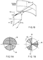
- FIG. 10 illustrates the cone-beam geometry.
- the algorithm could also be a stacked fan-beam algorithm, for example. One simply has to select an appropriate DIRECT condition for the chosen reconstruction algorithm. Gating points and available patches for the slice of interest are now defined.
- f (r ⁇ ) is the object to reconstruct
- R is the radius of the helical orbit
- H is the helical pitch (table feed per rotation)
- ( ⁇ , ⁇ , ⁇ ) denote projection-angle, ray-angle, and cone-angle, respectively (see FIG.
- Npatch denote the number of patches within 2 ⁇ m and let ip be the patch index from 0 to Npatch - 1.
- c ( i p , ⁇ ) ⁇ 1 if inside of patch i p 0 otherwise .
- c ( i p , ⁇ , ⁇ ) ⁇ 0 if ⁇ ⁇ ⁇ s ( i p ) triangle ( ⁇ / ⁇ m ) ⁇ rising [ ( ⁇ ⁇ ⁇ s ( i p ) ) / ⁇ f ] if ⁇ s ( i p ) ⁇ ⁇ ⁇ ⁇ s ( i p ) + ⁇ f triangle ( ⁇ / ⁇ m ) if ⁇ s ( i p ) + ⁇ f ⁇ ⁇ ⁇ ⁇ e ( i p ) ⁇ ⁇ f triangle ( ⁇ / ⁇ m ) ⁇ rising [ ( ⁇ e ( i p ) ⁇ ⁇ ) / ⁇ f ] if ⁇ e ( i p ) ⁇ f ⁇ ⁇ ⁇ ⁇ e ( i ) ⁇ ⁇ ⁇ ) / f
- Equation (41) the denominator of the argument of the triangle function does not have to be ⁇ m .
- the triangle function used therein is only an example.
- the function itself could also be Gaussian, trapezoid, etc.
- a cardiac banding artifact correction technique (CBC) is provided to reduce the effect of transition from one heart cycle to another heart cycle.
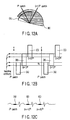
- FIGS. 12A-12C illustrate an example of the CBC concept.
- FIG. 12C shows the ECG signal wherein colored bold lines indicate patches, i.e., cardiac time window, gate window, or phase of interest in each heart cycle (or, heartbeat).
- FIG. 12B shows the corresponding z coverage of each patch with the same colored box.
- the darkness (grayscale) inside of each box represents the contribution of each patch to the slice at z.
- a darker shade of gray indicates a larger contribution to the slice at z.
- CBC is not applied in the left of FIG. 12B and the contributions of each patch display abrupt changes which yield banding artifacts. For example, the contribution of the blue (i+1) th path changes from 0 to 0.5 to 1 to 0.5 to 0 in discrete steps.
- the center and distance can be defined in terms of a projection angle.
- the center is then the angle P for which the focal spot is at the slice of interest and the distance to each patch is the angular range from the center to each projection angle ⁇ or the angle ⁇ corresponding to the gating point (or the center of each patch).
- FIG. 13 illustrates a trapezoid function which one might use.
- trapezoid ( x , a ) ⁇ 1 (
- w Weight ( i p ) ⁇ trapezoid (
- / ⁇ w , a w ) ⁇ based method and w Size ( i p ) ⁇ trapezoid (
- FIG. 12A illustrates the result, which is that the size (i.e., the contribution) of each patch smoothly changes along z. Specifically, at z 0 , where the patch
- CBC defines the size and weight for each patch rather than for each source point ⁇ or for each ray ( ⁇ , ⁇ ).
- the functions used in CBC have nothing to do with the redundancy weighting.
- the trapezoid function in References [4,5] must have a breaking point at the period of ⁇ in ⁇ (the parallel projection angle) whereas the trapezoid used herein, or any other function in CBC, has no such restriction.
- the shape of the function can be arbitrary. The best such functions are those that best suppress the effect of the transition from one cardiac cycle to another cycle, but no functions are excluded.
- weighting could be applied first and be followed by reconstruction.
- images corresponding to the different patches could be reconstructed first and then combined by weighting.
- CBC can also be used with other algorithms.
- CBC could be used with algorithms using connected patches with direct fan-beam or cone-beam algorithm or algorithms based on fan-to-parallel beam re-binning or cone-to-parallel fan-beam re-binning.
- CBC is used in continuous circular dynamic scanning.
- the distance and the center for CBC in this case can be along a time axis.
- the center is defined by the time center of interest in cine mode t ⁇ c , and the distance is measured by the distance along the time axis from the center to the projection angle P corresponding to the center of patch or each projection angle.
- t ⁇ c ( ⁇ ⁇ ⁇ ⁇ 0 ) ⁇ T rot / ( 2 ⁇ )
- t ⁇ c ( ⁇ ⁇ c ⁇ ⁇ 0 ) ⁇ T rot / ( 2 ⁇ )
- FIG. 14 illustrates a method for reconstructing an image according to embodiments of the present invention.
- computed tomography projection data are obtained using an X-ray detector and one of a cone-beam or fan-beam X-ray generator.
- the obtained projection data are weighted to compensate for redundant projection data.
- the weighted projection data are filtered using ramp-based filtering.
- the image is reconstructed by back-projecting the weighted projection data along a ray path.
- FIG. 15 illustrates a method for correcting cardiac banding artifacts according to embodiments of the present invention.
- computed tomography projection data are obtained using a multi-row X-ray detector and generator.
- step 1502 which occurs in parallel with step 1501
- a physiologic signal having first and second physiologic cycles is obtained.
- step 1503 first and second projection data corresponding to the first and second physiologic cycles are determined.
- step 1503 the first and second projection data are weighted so that their contribution changes gradually along a rotational axis of the helical trajectory.
- the image is reconstructed using the weighted first and second projection data.
- the method illustrated in FIG. 2 is based, for example, on a pair of projection. However, this is not limiting in any way and the method naturally expands to a plurality of projection data and physiologic cycles.
- FIG. 16 illustrates a system for carrying out embodiments of the present invention.
- a computed tomography (CT) device 1601 comprising a ray detector 1602 and a ray source 1603 are used to acquire temporally disconnected CT data.
- the data can be stored using a storage unit 1604.
- the data can be processed by a computing unit 1605 which includes a weighting device 1606, a filtering device 1607, and a reconstructing device 1608, to reconstruct a scanned object from the acquired disconnected projection data sets.
- the weighting device may also be configured to correct for cardiac banding artifacts.
- the system further comprises an image storing unit 1609 to store images obtained using the data and computing unit and a display device 1610 to display those same images.
- the computer housing may house a motherboard that contains a CPU, memory (e.g., DRAM, ROM, EPROM, EEPROM, SRAM, SDRAM, and Flash RAM), and other optional special purpose logic devices (e.g., ASICS) or configurable logic devices (e.g., GAL and reprogrammable FPGA).
- memory e.g., DRAM, ROM, EPROM, EEPROM, SRAM, SDRAM, and Flash RAM
- other optional special purpose logic devices e.g., ASICS
- configurable logic devices e.g., GAL and reprogrammable FPGA
- the computer also includes plural input devices, (e.g., keyboard and mouse), and a display card for controlling a monitor. Additionally, the computer may include a floppy disk drive; other removable media devices (e.g. compact disc, tape, and removable magneto-optical media); and a hard disk or other fixed high density media drives, connected using an appropriate device bus (e.g., a SCSI bus, an Enhanced IDE bus, or an Ultra DMA bus).
- the computer may also include a compact disc reader, a compact disc reader/writer unit, or a compact disc jukebox, which may be connected to the same device bus or to another device bus.
- Examples of computer readable media associated with the present invention include compact discs, hard disks, floppy disks, tape, magneto-optical disks, PROMs (e.g., EPROM, EEPROM, Flash EPROM), DRAM, SRAM, SDRAM, etc.
- PROMs e.g., EPROM, EEPROM, Flash EPROM
- DRAM DRAM
- SRAM SRAM
- SDRAM Secure Digital Random Access Memory
- the present invention includes software for controlling both the hardware of the computer and for enabling the computer to interact with a human user.
- Such software may include, but is not limited to, device drivers, operating systems and user applications, such as development tools.
- Computer program products of the present invention include any computer readable medium which stores computer program instructions (e.g., computer code devices) which when executed by a computer causes the computer to perform the method of the present invention.
- the computer code devices of the present invention may be any interpretable or executable code mechanism, including but not limited to, scripts, interpreters, dynamic link libraries, Java classes, and complete executable programs. Moreover, parts of the processing of the present invention may be distributed (e.g., between (1) multiple CPUs or (2) at least one CPU and at least one configurable logic device) for better performance, reliability, and/or cost. For example, an outline or image may be selected on a first computer and sent to a second computer for remote diagnosis.
Landscapes
- Life Sciences & Earth Sciences (AREA)
- Engineering & Computer Science (AREA)
- Health & Medical Sciences (AREA)
- Physics & Mathematics (AREA)
- Medical Informatics (AREA)
- Radiology & Medical Imaging (AREA)
- Heart & Thoracic Surgery (AREA)
- High Energy & Nuclear Physics (AREA)
- Theoretical Computer Science (AREA)
- Nuclear Medicine, Radiotherapy & Molecular Imaging (AREA)
- Optics & Photonics (AREA)
- Pathology (AREA)
- General Physics & Mathematics (AREA)
- Biomedical Technology (AREA)
- Biophysics (AREA)
- Molecular Biology (AREA)
- Surgery (AREA)
- Animal Behavior & Ethology (AREA)
- General Health & Medical Sciences (AREA)
- Public Health (AREA)
- Veterinary Medicine (AREA)
- Apparatus For Radiation Diagnosis (AREA)
- Image Processing (AREA)
- Image Analysis (AREA)
Applications Claiming Priority (2)
| Application Number | Priority Date | Filing Date | Title |
|---|---|---|---|
| US65821005P | 2005-03-04 | 2005-03-04 | |
| US11/094,468 US20060198491A1 (en) | 2005-03-04 | 2005-03-31 | Volumetric computed tomography system for imaging |
Publications (2)
| Publication Number | Publication Date |
|---|---|
| EP1699014A2 true EP1699014A2 (de) | 2006-09-06 |
| EP1699014A3 EP1699014A3 (de) | 2009-08-19 |
Family
ID=36576015
Family Applications (1)
| Application Number | Title | Priority Date | Filing Date |
|---|---|---|---|
| EP05018698A Withdrawn EP1699014A3 (de) | 2005-03-04 | 2005-08-29 | Bildgebende anordnung volumetrischer Computertomographie |
Country Status (3)
| Country | Link |
|---|---|
| US (1) | US20060198491A1 (de) |
| EP (1) | EP1699014A3 (de) |
| JP (1) | JP2006239390A (de) |
Cited By (1)
| Publication number | Priority date | Publication date | Assignee | Title |
|---|---|---|---|---|
| CN103489206A (zh) * | 2013-09-25 | 2014-01-01 | 华南理工大学 | 一种基于扇束x光ct滤波反投影重建的混合滤波方法 |
Families Citing this family (20)
| Publication number | Priority date | Publication date | Assignee | Title |
|---|---|---|---|---|
| JP4828839B2 (ja) * | 2005-03-07 | 2011-11-30 | 株式会社東芝 | X線コンピュータ断層撮影装置、画像処理装置及び画像処理方法 |
| JP2008539930A (ja) * | 2005-05-12 | 2008-11-20 | コーニンクレッカ フィリップス エレクトロニクス エヌ ヴィ | 超短スキャン及び最新データのより強い重み付けを実行する連続コンピュータ断層撮影 |
| DE602006019292D1 (de) * | 2005-09-13 | 2011-02-10 | Philips Intellectual Property | Effiziente schrittweise vierdimensionale rekonstruktion von kardialer 3d-computertomographie |
| US8364244B2 (en) * | 2005-11-23 | 2013-01-29 | General Electric Company | Methods and systems to facilitate reducing banding artifacts in images |
| US7409033B2 (en) * | 2006-05-31 | 2008-08-05 | The Board Of Trustees Of The Leland Stanford Junior University | Tomographic reconstruction for x-ray cone-beam scan data |
| JP5175290B2 (ja) * | 2006-10-11 | 2013-04-03 | エレクタ、アクチボラグ | 放射線装置 |
| JP5220368B2 (ja) * | 2007-09-03 | 2013-06-26 | ジーイー・メディカル・システムズ・グローバル・テクノロジー・カンパニー・エルエルシー | X線ct装置 |
| US7792238B2 (en) * | 2008-02-18 | 2010-09-07 | General Electric Company | Method and system for reconstructing cone-beam projection data with reduced artifacts |
| US8284892B2 (en) * | 2008-12-22 | 2012-10-09 | General Electric Company | System and method for image reconstruction |
| JP5667172B2 (ja) * | 2009-05-18 | 2015-02-12 | コーニンクレッカ フィリップス エヌ ヴェ | 補間不要な、扇形平行ビーム・リビニング |
| US9235907B2 (en) * | 2012-03-20 | 2016-01-12 | Juan C. Ramirez Giraldo | System and method for partial scan artifact reduction in myocardial CT perfusion |
| US8948337B2 (en) | 2013-03-11 | 2015-02-03 | General Electric Company | Computed tomography image reconstruction |
| US9662084B2 (en) | 2015-06-18 | 2017-05-30 | Toshiba Medical Systems Corporation | Method and apparatus for iteratively reconstructing tomographic images from electrocardiographic-gated projection data |
| EP3244368A1 (de) * | 2016-05-13 | 2017-11-15 | Stichting Katholieke Universiteit | Rauschverminderung in bilddaten |
| DE102016219709B3 (de) * | 2016-10-11 | 2018-03-01 | Siemens Healthcare Gmbh | Verfahren zur Ermittlung eines Perfusionsdatensatzes, sowie Röntgenvorrichtung, Computerprogramm und elektronisch lesbarer Datenträger |
| KR102555465B1 (ko) * | 2018-06-11 | 2023-07-17 | 삼성전자주식회사 | 단층 영상의 생성 방법 및 그에 따른 엑스선 영상 장치 |
| DE102019200269A1 (de) | 2019-01-11 | 2020-07-16 | Siemens Healthcare Gmbh | Bereitstellen eines Beschränkungsbilddatensatzes und/oder eines Differenzbilddatensatzes |
| DE102019200270A1 (de) * | 2019-01-11 | 2020-07-16 | Siemens Healthcare Gmbh | Bereitstellen eines Differenzbilddatensatzes und Bereitstellen einer trainierten Funktion |
| US10786212B1 (en) | 2019-05-31 | 2020-09-29 | MinFound Medical Systems Co., Ltd. | System and method of helical cardiac cone beam reconstruction |
| EP3977937A1 (de) | 2020-09-30 | 2022-04-06 | FEI Company | Verfahren zur untersuchung einer probe unter verwendung einer tomographischen bilderzeugungsvorrichtung |
Family Cites Families (14)
| Publication number | Priority date | Publication date | Assignee | Title |
|---|---|---|---|---|
| US5430783A (en) * | 1992-08-07 | 1995-07-04 | General Electric Company | Reconstruction method for helical scanning computed tomography apparatus with multi-row detector array employing overlapping beams |
| US5881123A (en) * | 1998-03-31 | 1999-03-09 | Siemens Corporate Research, Inc. | Simplified cone beam image reconstruction using 3D backprojection |
| US6243437B1 (en) * | 1998-11-25 | 2001-06-05 | General Electric Company | Coronary calcification detection using retrospective cardiac gating of imaging system |
| DE19946092A1 (de) * | 1999-09-25 | 2001-03-29 | Philips Corp Intellectual Pty | Verfahren und Vorrichtung zur Ermittlung eines 3D-Bilddatensatzes eines sich periodisch bewegenden Körperorgans |
| DE19957082B4 (de) * | 1999-11-28 | 2004-08-26 | Siemens Ag | Verfahren zur Untersuchung eines eine periodische Bewegung ausführenden Körperbereichs |
| US6324241B1 (en) * | 1999-12-30 | 2001-11-27 | Ge Medical Systems Global Technology Company, Llc | Method and apparatus for CT reconstruction |
| WO2002026135A1 (en) * | 2000-09-29 | 2002-04-04 | Ge Medical Systems Global Technology Company, Llc | Phase-driven multisector reconstruction for multislice helical ct imaging |
| US6426990B1 (en) * | 2001-06-28 | 2002-07-30 | General Electric Company | Methods and apparatus for coronary-specific imaging reconstruction |
| US6438196B1 (en) * | 2001-06-28 | 2002-08-20 | General Electric Company | EKG driven CT image reconstruction for cardiac imaging |
| US6771732B2 (en) * | 2002-02-28 | 2004-08-03 | The Board Of Trustees Of The University Of Illinois | Methods and apparatus for fast divergent beam tomography |
| DE602004021683D1 (de) * | 2003-04-10 | 2009-08-06 | Koninkl Philips Electronics Nv | Computertomographische methode für ein sich periodisch bewegendes objekt |
| US6999550B2 (en) * | 2004-02-09 | 2006-02-14 | Ge Medical Systems Global Technology | Method and apparatus for obtaining data for reconstructing images of an object |
| US7215734B2 (en) * | 2004-06-30 | 2007-05-08 | General Electric Company | Method and system for three-dimensional reconstruction of images |
| US7424088B2 (en) * | 2004-09-29 | 2008-09-09 | Kabushiki Kaisha Toshiba | Image reconstruction method using Hilbert transform |
-
2005
- 2005-03-31 US US11/094,468 patent/US20060198491A1/en not_active Abandoned
- 2005-08-24 JP JP2005243189A patent/JP2006239390A/ja not_active Withdrawn
- 2005-08-29 EP EP05018698A patent/EP1699014A3/de not_active Withdrawn
Non-Patent Citations (4)
| Title |
|---|
| MANZKE R ET AL: "Adaptive temporal resolution optimization in helical cardiac cone beam CT reconstruction" MEDICAL PHYSICS, AIP, MELVILLE, NY, US, vol. 30, no. 12, 1 December 2003 (2003-12-01), pages 3072-3080, XP002342106 ISSN: 0094-2405 * |
| NOO F ET AL: "Image reconstruction from fan-beam projections on less than a short scan" 21 July 2002 (2002-07-21), PHYSICS IN MEDICINE AND BIOLOGY, TAYLOR AND FRANCIS LTD. LONDON, GB, PAGE(S) 2525 - 2546 , XP002358039 ISSN: 0031-9155 * the whole document * * |
| PARKER D L: "OPTIMAL SHORT SCAN CONVOLUTION RECONSTRUCTION FOR FANBEAM CT" MEDICAL PHYSICS, AIP, MELVILLE, NY, US, vol. 9, no. 2, 1 March 1982 (1982-03-01), pages 254-257, XP000615150 ISSN: 0094-2405 * |
| ZAMYATIN A A ET AL: "Practical hybrid convolution algorithm for helical CT reconstruction" NUCLEAR SCIENCE SYMPOSIUM CONFERENCE RECORD, 2004 IEEE, IEEE, PISCATAWAY, NJ, USA, vol. 5, 16 October 2004 (2004-10-16), pages 3003-3007, XP010819324 ISBN: 978-0-7803-8700-3 * |
Cited By (1)
| Publication number | Priority date | Publication date | Assignee | Title |
|---|---|---|---|---|
| CN103489206A (zh) * | 2013-09-25 | 2014-01-01 | 华南理工大学 | 一种基于扇束x光ct滤波反投影重建的混合滤波方法 |
Also Published As
| Publication number | Publication date |
|---|---|
| US20060198491A1 (en) | 2006-09-07 |
| EP1699014A3 (de) | 2009-08-19 |
| JP2006239390A (ja) | 2006-09-14 |
Similar Documents
| Publication | Publication Date | Title |
|---|---|---|
| EP1699014A2 (de) | Bildgebende anordnung volumetrischer Computertomographie | |
| Tang et al. | A three-dimensional-weighted cone beam filtered backprojection (CB-FBP) algorithm for image reconstruction in volumetric CT—helical scanning | |
| Grass et al. | Helical cardiac cone beam reconstruction using retrospective ECG gating | |
| US6944260B2 (en) | Methods and apparatus for artifact reduction in computed tomography imaging systems | |
| EP1562478B1 (de) | Kegelstrahl computertomographische bildgebung | |
| CN100493456C (zh) | X-射线ct设备 | |
| Tang et al. | A three-dimensional weighted cone beam filtered backprojection (CB-FBP) algorithm for image reconstruction in volumetric CT under a circular source trajectory | |
| Stierstorfer et al. | Segmented multiple plane reconstruction: a novel approximate reconstruction scheme for multi-slice spiral CT | |
| US9662084B2 (en) | Method and apparatus for iteratively reconstructing tomographic images from electrocardiographic-gated projection data | |
| CN103390284B (zh) | 在扩展的测量场中的ct图像重建 | |
| JP2002330956A (ja) | 一般化された螺旋補間アルゴリズムを用いた方法及び装置 | |
| EP1489559B1 (de) | Vorrichtung zur Rekonstruktion von Kegelstrahlprojektionsdaten und Vorrichtung zur Computertomografie | |
| JP2006095297A (ja) | スキャン対象に関するct画像内の再構成点における画像データ値を決定する再構成方法及びx線コンピュータ断層撮影装置 | |
| EP1663004A2 (de) | Computertomographie-verfahren unter anwendung eines kegelförmigen strahlenbündels | |
| US6775347B2 (en) | Methods and apparatus for reconstructing an image of an object | |
| US7050527B2 (en) | Methods and apparatus for artifact reduction in cone beam CT image reconstruction | |
| Koken et al. | Aperture weighted cardiac reconstruction for cone-beam CT | |
| Taguchi et al. | Direct cone‐beam cardiac reconstruction algorithm with cardiac banding artifact correction | |
| Manzke et al. | Helical cardiac cone beam CT reconstruction with large area detectors: a simulation study | |
| US6999550B2 (en) | Method and apparatus for obtaining data for reconstructing images of an object | |
| Nett et al. | Arc based cone-beam reconstruction algorithm using an equal weighting scheme | |
| JP5572386B2 (ja) | 関心領域を撮像する撮像システム、撮像方法及びコンピュータプログラム | |
| Tang et al. | A helical cone-beam filtered backprojection (CB-FBP) reconstruction algorithm using 3D view weighting | |
| US20060013357A1 (en) | Methods and apparatus for 3D reconstruction in helical cone beam volumetric CT | |
| Tang et al. | Performance study of the temporal resolution improvement using prior image constrained compressed sensing (TRI-PICCS) |
Legal Events
| Date | Code | Title | Description |
|---|---|---|---|
| PUAI | Public reference made under article 153(3) epc to a published international application that has entered the european phase |
Free format text: ORIGINAL CODE: 0009012 |
|
| 17P | Request for examination filed |
Effective date: 20050829 |
|
| AK | Designated contracting states |
Kind code of ref document: A2 Designated state(s): AT BE BG CH CY CZ DE DK EE ES FI FR GB GR HU IE IS IT LI LT LU LV MC NL PL PT RO SE SI SK TR |
|
| AX | Request for extension of the european patent |
Extension state: AL BA HR MK YU |
|
| PUAL | Search report despatched |
Free format text: ORIGINAL CODE: 0009013 |
|
| AK | Designated contracting states |
Kind code of ref document: A3 Designated state(s): AT BE BG CH CY CZ DE DK EE ES FI FR GB GR HU IE IS IT LI LT LU LV MC NL PL PT RO SE SI SK TR |
|
| AX | Request for extension of the european patent |
Extension state: AL BA HR MK YU |
|
| 17Q | First examination report despatched |
Effective date: 20090918 |
|
| AKX | Designation fees paid |
Designated state(s): DE NL |
|
| STAA | Information on the status of an ep patent application or granted ep patent |
Free format text: STATUS: THE APPLICATION IS DEEMED TO BE WITHDRAWN |
|
| 18D | Application deemed to be withdrawn |
Effective date: 20100330 |