EP1698929B1 - Objectif et microscope - Google Patents
Objectif et microscope Download PDFInfo
- Publication number
- EP1698929B1 EP1698929B1 EP20060001362 EP06001362A EP1698929B1 EP 1698929 B1 EP1698929 B1 EP 1698929B1 EP 20060001362 EP20060001362 EP 20060001362 EP 06001362 A EP06001362 A EP 06001362A EP 1698929 B1 EP1698929 B1 EP 1698929B1
- Authority
- EP
- European Patent Office
- Prior art keywords
- layers
- light
- aperture
- carrier
- detection
- Prior art date
- Legal status (The legal status is an assumption and is not a legal conclusion. Google has not performed a legal analysis and makes no representation as to the accuracy of the status listed.)
- Not-in-force
Links
- 238000005286 illumination Methods 0.000 claims description 51
- 238000001514 detection method Methods 0.000 claims description 36
- 210000001747 pupil Anatomy 0.000 claims description 12
- 239000011521 glass Substances 0.000 claims description 9
- 239000011248 coating agent Substances 0.000 claims description 4
- 238000000576 coating method Methods 0.000 claims description 4
- 238000001917 fluorescence detection Methods 0.000 claims 1
- 230000003287 optical effect Effects 0.000 description 8
- 230000005284 excitation Effects 0.000 description 7
- 238000000204 total internal reflection microscopy Methods 0.000 description 4
- 239000013307 optical fiber Substances 0.000 description 3
- 230000008878 coupling Effects 0.000 description 2
- 238000010168 coupling process Methods 0.000 description 2
- 238000005859 coupling reaction Methods 0.000 description 2
- 239000006059 cover glass Substances 0.000 description 2
- 238000000034 method Methods 0.000 description 2
- 230000002093 peripheral effect Effects 0.000 description 2
- 230000008569 process Effects 0.000 description 2
- 230000009467 reduction Effects 0.000 description 2
- 238000004621 scanning probe microscopy Methods 0.000 description 2
- 238000000492 total internal reflection fluorescence microscopy Methods 0.000 description 2
- 230000007704 transition Effects 0.000 description 2
- 230000002411 adverse Effects 0.000 description 1
- 230000001609 comparable effect Effects 0.000 description 1
- 230000007423 decrease Effects 0.000 description 1
- 230000001419 dependent effect Effects 0.000 description 1
- 238000011161 development Methods 0.000 description 1
- 230000018109 developmental process Effects 0.000 description 1
- 238000005516 engineering process Methods 0.000 description 1
- 239000000835 fiber Substances 0.000 description 1
- 238000013507 mapping Methods 0.000 description 1
- XLYOFNOQVPJJNP-UHFFFAOYSA-N water Substances O XLYOFNOQVPJJNP-UHFFFAOYSA-N 0.000 description 1
Images
Classifications
-
- G—PHYSICS
- G01—MEASURING; TESTING
- G01N—INVESTIGATING OR ANALYSING MATERIALS BY DETERMINING THEIR CHEMICAL OR PHYSICAL PROPERTIES
- G01N21/00—Investigating or analysing materials by the use of optical means, i.e. using sub-millimetre waves, infrared, visible or ultraviolet light
- G01N21/62—Systems in which the material investigated is excited whereby it emits light or causes a change in wavelength of the incident light
- G01N21/63—Systems in which the material investigated is excited whereby it emits light or causes a change in wavelength of the incident light optically excited
- G01N21/64—Fluorescence; Phosphorescence
- G01N21/645—Specially adapted constructive features of fluorimeters
- G01N21/6456—Spatial resolved fluorescence measurements; Imaging
- G01N21/6458—Fluorescence microscopy
-
- G—PHYSICS
- G02—OPTICS
- G02B—OPTICAL ELEMENTS, SYSTEMS OR APPARATUS
- G02B21/00—Microscopes
- G02B21/02—Objectives
-
- G—PHYSICS
- G02—OPTICS
- G02B—OPTICAL ELEMENTS, SYSTEMS OR APPARATUS
- G02B21/00—Microscopes
- G02B21/06—Means for illuminating specimens
-
- G—PHYSICS
- G02—OPTICS
- G02B—OPTICAL ELEMENTS, SYSTEMS OR APPARATUS
- G02B21/00—Microscopes
- G02B21/06—Means for illuminating specimens
- G02B21/08—Condensers
- G02B21/082—Condensers for incident illumination only
- G02B21/084—Condensers for incident illumination only having annular illumination around the objective
-
- G—PHYSICS
- G02—OPTICS
- G02B—OPTICAL ELEMENTS, SYSTEMS OR APPARATUS
- G02B21/00—Microscopes
- G02B21/16—Microscopes adapted for ultraviolet illumination ; Fluorescence microscopes
Definitions
- the present invention relates to a microscope with an objective and a light source for the evanescent illumination of a sample, wherein the illumination light has a focus in the plane of the objective pupil.
- the refraction behavior of light is used in the transition from an optically denser to an optically thinner medium.
- a stationary evanescent wave forms in the medium with a lower refractive index.
- the intensity of this well decreases exponentially with the distance to the interface. Because of this, fluorophores farther from the interface are not excited.
- the background fluorescence is significantly reduced.
- the image contrast is improved and the resolution is simultaneously increased significantly.
- a prerequisite for the use of the above-described phenomenon is a sufficiently large difference in the refractive indices of cover glass and medium.
- a microscope with evanescent illumination of a sample is already known.
- the microscope includes a white light source whose light is coupled via a slit through the microscope objective into the specimen carrying slide for evanescent illumination.
- the illumination light propagates in the slide by total internal reflection, whereby the illumination of the sample takes place only in the region of the projecting from the slide evanescent field.
- Microscopes of this type are known by the term TIRFM (Total Internal Reflection Fluorescent Microscope).
- the z-resolution of TIRF microscopes is exceptionally good due to the evanescent field projecting only about 100 nm into the sample.
- the objective consists of a first lens having a positive refractive power, a second lens having a negative refractive power, the focal length ratio between the two lenses being in the range of -0.4 and -0.1 and the total refractive power being greater than zero. Furthermore, the lens includes two positive lenses whose focal diameter to focal length is greater than 0.3 and less than 0.6. Further, the objective includes a negative lens and a condenser lens, the negative lens facing the front group, and the focal length ratio of the negative lens and the condenser lens being between -0.5 and -2.
- the microscope has a microscope housing and a lens.
- the illumination light emanating from a lighting device can be coupled in via an adapter which can be inserted into the microscope housing.
- the illumination system includes a laser light source whose light is coupled into an optical fiber. Furthermore, a coupling-out optical system is provided, which focuses the light emerging from the fiber into a rear focal point of the microscope objective.
- the optical fiber is displaceable in a plane perpendicular to the optical axis of the microscope objective.
- From the DE 102 29 935 A1 is a device for coupling light in a microscope known. There, laser light is directed onto the specimen in the field diaphragm plane by means of an optical fiber coupling designed as a slide.
- the invention is particularly suitable for the TIRF process.
- a sample is illuminated with a light beam to observe the detection light emitted by the sample, as reflection or fluorescent light.
- the focus of an illumination light beam is moved by means of a controllable beam deflection device, generally by tilting two mirrors, in a sample plane, wherein the deflection axes are usually perpendicular to one another, so that one mirror deflects in the x direction and the other in the y direction.
- the tilting of the mirror is accomplished, for example, with the help of galvanometer actuators.
- the power of the detection light coming from the object is measured as a function of the position of the scanning beam.
- the control elements are equipped with sensors for determining the current mirror position.
- an object with the focus of a light beam is scanned in three dimensions.
- a confocal scanning microscope generally comprises a light source, a focusing optics, with which the light of the source is focused on a pinhole - the so-called excitation diaphragm, a beam splitter, a beam deflector for beam control, a microscope optics, a detection aperture and the detectors for detecting the detection - or fluorescent light.
- the illumination light is coupled in via a beam splitter.
- the fluorescence or reflection light coming from the object passes back to the beam splitter via the beam deflection device, passes through it, and is then focused on the detection aperture behind which the detectors are located.
- This detection arrangement is called Descan arrangement.
- Detection light that does not come directly from the focus region takes a different light path and does not pass through the detection aperture, so as to obtain point information that results in a three-dimensional image by sequentially scanning the object with the focus of the illumination light beam.
- a three-dimensional image is achieved by layerwise image data acquisition.
- the present invention has for its object to provide a simply executed total internal reflection microscope with a lens, wherein the lens can be used in the conventional beam path of the illumination light and the detection light.
- the microscope according to the invention achieves the above object by the features of claim 1. Thereafter, the generic microscope is characterized in that in the vicinity or in the plane of the objective pupil an aperture is provided and that the aperture permeable to the illumination light and permeable to the detection light Central area and having an illumination light permeable edge area.
- an evanescent illumination of a sample through the objective can be realized in a constructively simple manner, namely by providing a special structural measure in the vicinity or in the plane of the objective pupil, namely a special diaphragm.
- This diaphragm is designed to have an illuminating light-impermeable and detection-light-transmitting central area and an illuminating-light-transmitting peripheral area.
- the excitation light is blocked in the central region and can only pass at the pupil edge and then penetrate into the sample at a shallow angle.
- the detection light coming from the sample for example fluorescent light, can be recorded over the full objective aperture, since the central region is permeable to the detection light. In the simplest case, i. without limitation of the observation aperture, also permeable to the detection light.
- the edge region for the detection light i. is impermeable to the fluorescent light coming from the sample.
- a reduction of the reivapertur or observation aperture takes place.
- the fluorescent light emitted by the sample can not pass the edge area and is accordingly blocked in the edge area.
- the central region of the diaphragm which blocks the illumination light, is designed as a circular surface.
- the edge region closes in a further advantageous manner immediately around the circular surface and extends around it as an annular surface.
- This ring surface may be transparent (full lens aperture) or impermeable (reduced lens aperture) as described above for the detection light.
- the differently transmissive regions-central region and edge region-of the diaphragm are embodied according to the invention as thin layers, preferably applied to a light-transmitting carrier. These layers can be vapor-deposited on the carrier. The layers can be produced by a wide variety of lithographic processes.
- the layers are interference layers, which results in a wavelength-dependent influencing of the light.
- the layers may be multiband interference layers so that multiple fluorescence excitations can occur simultaneously. Such a design speaks for a universal usability of the lens.
- the carrier of the layers is generally a glass surface.
- the glass surface may be the surface of a glass plate integrated in the lens.
- the surface of a lens serves as a carrier of the layers, wherein the lens can be flattened on the side carrying the layer.
- the application of the layers on curved surfaces is also conceivable, whereby a comparable effect can be achieved.
- the microscope in the illumination beam path comprises an illumination filter or excitation filter
- this illumination filter has the same coating as the edge region of the diaphragm or of the carrier.
- the illumination filter is advantageously arranged between a lighting diaphragm (field diaphragm) and optionally an optical system and a beam splitter, preferably in the region of a parallel aligned illumination light.
- a detection filter is arranged in front of the detector in the detection beam path. There passes through the beam splitter through the return of the sample emission light, which could happen in the lens, the central region of the diaphragm.
- the detection filter has the same coating as the central region of the diaphragm or of the carrier, so that a vote also takes place in this respect.
- the detection filter avoids, inter alia, that unwanted scattered light reaches the detector.
- the observation aperture is defined by the size of the central area as well as by the size of the peripheral area through which the detection light can not pass.
- the detection filter can be arranged in the detection beam path between the beam splitter and the detector at arbitrary locations.
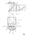
- the single FIGURE shows an exemplary embodiment of an objective 1 according to the invention in the beam path 2 of a microscope according to the invention, wherein only individual components of the microscope are shown here.
- Illumination light 3 comes from a laser light source, not shown in the figure, and passes through an illumination diaphragm 4 through an optics 5 which parallel the light and through an illumination filter 6 to a beam splitter 7.
- the illumination light 3 is guided along the optical axis 8 through the lens 1.
- the objective 1 is shown in simplified form and, in addition to the objective housing 9, comprises an indicated front lens 10 and a further lens 11.
- the plane of the objective pupil is indicated by the arrows indicated by reference numeral 12.
- a diaphragm 13 is provided in the plane of the objective pupil, wherein the diaphragm 13 has a central region 15, which is impermeable to the illumination light 3 and permeable to the detection light 14, and an edge region 16 which is permeable to the illumination light 3.
- the fluorescent light emitted by the sample not shown in the figure passes along the optical axis 8 through the front lens 10 and the further lens 11 through a glass body 17 which serves with its flat surface 18 as a support for vapor-deposited layers 19, 20.
- These layers 19, 20 ultimately form the diaphragm 13, the emitted light, ie the detection light 14, passing through the central region 15 and through the layer 19 deposited thereon out of the objective 1 to the beam splitter 7 and through it a detection filter 21 can happen. From there, the detection light 14 reaches the detector, which is not shown in the figure.
- both the illumination filter 6 and the detection filter 21 are coated, namely with the same layers as are vapor-deposited on the glass body 17 in the objective 1.
- the illumination filter 6 carries the same vapor-deposited layer 20, as it is vapor-deposited in the edge region 16 of the glass body 17.
- the detection filter 21 carries the same vapor-deposited layer 19, as it is vapor-deposited in the central region 15 of the glass body 17.
Landscapes
- Physics & Mathematics (AREA)
- Chemical & Material Sciences (AREA)
- Analytical Chemistry (AREA)
- General Physics & Mathematics (AREA)
- Optics & Photonics (AREA)
- Health & Medical Sciences (AREA)
- Nuclear Medicine, Radiotherapy & Molecular Imaging (AREA)
- Life Sciences & Earth Sciences (AREA)
- Biochemistry (AREA)
- General Health & Medical Sciences (AREA)
- Immunology (AREA)
- Pathology (AREA)
- Microscoopes, Condenser (AREA)
- Lenses (AREA)
- Investigating, Analyzing Materials By Fluorescence Or Luminescence (AREA)
Claims (10)
- Microscope, comprenant
une source lumineuse pour l'éclairage évanescent d'un échantillon,
un objectif (1), aussi bien de la lumière d'éclairage (3) qu'également de la lumière de détection (14) étant guidées à travers l'objectif (1) et la lumière d'éclairage (3) présentant un foyer dans le plan de la pupille de l'objectif, ainsi
qu'un diaphragme (13) disposé au voisinage ou dans le plan de la pupille de l'objectif, le diaphragme (13) présentant une zone (15) centrale opaque pour la lumière d'éclairage ainsi que transparente pour la lumière de détection de fluorescence (14) et une zone de bord (16) transparente pour la lumière d'éclairage (3),
caractérisé par le fait que les zones (15, 16) de transparences différentes du diaphragme (13) sont réalisées sous la forme de couches minces (19, 20) et qu'un filtre d'éclairage (6) est disposé dans la marche des rayons d'éclairage (3) et/ou un filtre de détection (21) dans la marche des rayons de détection, le filtre d'éclairage (6) présentant la même enduction que la zone (16) de bord du diaphragme (13) et le filtre de détection (21) la même enduction que la zone (15) centrale du diaphragme (13). - Microscope selon la revendication 1, caractérisé par le fait que la zone (16) de bord du diaphragme (13) est opaque pour la lumière de détection (14).
- Microscope selon la revendication 1 ou 2, caractérisé par le fait que la zone (15) centrale du diaphragme (13) est réalisée sous la forme d'une surface circulaire, la zone (16) de bord pouvant être réalisée sous la forme d'une surface annulaire s'étendant directement autour de la surface circulaire.
- Microscope selon l'une des revendications 1 à 3, caractérisé par le fait que les couches (19, 20) sont déposées sur un support (17) transparent à la lumière, les couches (19, 20) pouvant être métallisées sous vide sur le support (17).
- Microscope selon l'une des revendications 1 à 4, caractérisé par le fait qu'il s'agit pour les couches (19, 20) de couches d'interférence, de préférence de couches d'interférence à bandes multiples.
- Microscope selon l'une des revendications 1 à 5, caractérisé par le fait qu'une surface de verre sert de support (17) des couches (19, 20), la surface d'une plaquette de verre pouvant servir en tant que support (17) des couches (19, 20) ou la surface d'une lentille en tant que support (17) des couches (19, 20).
- Microscope selon l'une des revendications 1 à 6, caractérisé par le fait que le support (17) est réalisé plan sur la face portant les couches (19, 20).
- Microscope selon l'une des revendications 1 à 7, caractérisé par le fait que les couches (19, 20) sont formées sur la face du support (17) écartée de l'objet et/ou que les couches (19, 20) sont formées sur la face du support (17) tournée vers l'objet.
- Microscope selon l'une des revendications 1 à 8, caractérisé par le fait que le filtre d'éclairage (6) est disposé entre le diaphragme d'éclairage (4) et le cas échéant une optique (5) et une lame séparatrice (7), de préférence dans la zone d'une lumière d'éclairage (3) parallèle.
- Microscope selon l'une des revendications 1 à 9, caractérisé par le fait que le filtre de détection (21) est disposé entre la lame séparatrice (7) et un détecteur.
Applications Claiming Priority (1)
| Application Number | Priority Date | Filing Date | Title |
|---|---|---|---|
| DE200510009832 DE102005009832A1 (de) | 2005-03-01 | 2005-03-01 | Objektiv und Mikroskop |
Publications (2)
| Publication Number | Publication Date |
|---|---|
| EP1698929A1 EP1698929A1 (fr) | 2006-09-06 |
| EP1698929B1 true EP1698929B1 (fr) | 2008-07-30 |
Family
ID=36218595
Family Applications (1)
| Application Number | Title | Priority Date | Filing Date |
|---|---|---|---|
| EP20060001362 Not-in-force EP1698929B1 (fr) | 2005-03-01 | 2006-01-23 | Objectif et microscope |
Country Status (4)
| Country | Link |
|---|---|
| EP (1) | EP1698929B1 (fr) |
| JP (1) | JP5039307B2 (fr) |
| CN (1) | CN1828357A (fr) |
| DE (2) | DE102005009832A1 (fr) |
Families Citing this family (8)
| Publication number | Priority date | Publication date | Assignee | Title |
|---|---|---|---|---|
| US7855844B2 (en) | 2007-05-17 | 2010-12-21 | Mitutoyo Corporation | Objective lens and optical measuring device |
| DE102010034122B4 (de) | 2010-08-12 | 2020-03-26 | Carl Zeiss Microscopy Gmbh | Mikroskop und Objektiv, insbesondere für die TIRF-Mikroskopie |
| JP5834638B2 (ja) * | 2011-09-02 | 2015-12-24 | 株式会社ニコン | 対物レンズユニット及びこの対物レンズユニットを有する走査型顕微鏡 |
| CN102818796B (zh) * | 2012-07-23 | 2016-01-27 | 苏州生物医学工程技术研究所 | 生物荧光显微检测仪器 |
| CN102818794B (zh) * | 2012-07-23 | 2016-01-27 | 苏州生物医学工程技术研究所 | 生物荧光显微检测仪器 |
| CN102818795B (zh) * | 2012-07-23 | 2015-08-26 | 苏州生物医学工程技术研究所 | 生物荧光显微检测仪器 |
| DE102017214189A1 (de) * | 2017-08-15 | 2019-02-21 | Carl Zeiss Microscopy Gmbh | Verfahren zum Betrieb einer Mikroskopieranordnung und Mikroskopieranordnung mit einem ersten Mikroskop und mindestens einem weiteren Mikroskop |
| CN109100352B (zh) * | 2018-08-30 | 2024-07-23 | 天津港东科技股份有限公司 | 显微镜多功能液体测试装置 |
Family Cites Families (10)
| Publication number | Priority date | Publication date | Assignee | Title |
|---|---|---|---|---|
| JP4671463B2 (ja) | 2000-03-24 | 2011-04-20 | オリンパス株式会社 | 照明光学系及び照明光学系を備えた顕微鏡 |
| US6597499B2 (en) * | 2001-01-25 | 2003-07-22 | Olympus Optical Co., Ltd. | Total internal reflection fluorescence microscope having a conventional white-light source |
| DE10108796A1 (de) | 2001-02-21 | 2002-09-05 | Zeiss Carl Jena Gmbh | Hochaperturiges Objektiv |
| DE10143481A1 (de) | 2001-09-05 | 2003-03-20 | Europ Lab Molekularbiolog | Mikroskop |
| JP2003098439A (ja) * | 2001-09-25 | 2003-04-03 | Olympus Optical Co Ltd | 観察切り替え可能な顕微鏡 |
| DE10217098B4 (de) | 2002-04-17 | 2004-04-15 | Carl Zeiss Jena Gmbh | Auflicht-Beleuchtungsanordnung für ein Mikroskop |
| DE10229935B4 (de) | 2002-07-04 | 2018-02-08 | Carl Zeiss Microscopy Gmbh | Mikroskopschieber zur Einkopplung von Licht in ein Mikroskop |
| DE10309269B4 (de) * | 2003-03-03 | 2005-06-02 | Till Photonics Gmbh | Vorrichtung für Totale Interne Reflexions-Mikroskopie |
| DE102004015587A1 (de) * | 2003-04-04 | 2004-11-11 | Olympus Corporation | Fluoreszenzmikroskop mit totaler interner Reflexion |
| DE10344410A1 (de) * | 2003-09-25 | 2005-04-28 | Leica Microsystems | Rastermikroskop mit evaneszenter Beleuchtung |
-
2005
- 2005-03-01 DE DE200510009832 patent/DE102005009832A1/de not_active Withdrawn
-
2006
- 2006-01-23 DE DE200650001206 patent/DE502006001206D1/de active Active
- 2006-01-23 EP EP20060001362 patent/EP1698929B1/fr not_active Not-in-force
- 2006-02-21 JP JP2006043796A patent/JP5039307B2/ja not_active Expired - Fee Related
- 2006-03-01 CN CNA2006100198198A patent/CN1828357A/zh active Pending
Also Published As
| Publication number | Publication date |
|---|---|
| EP1698929A1 (fr) | 2006-09-06 |
| DE102005009832A1 (de) | 2006-09-07 |
| JP2006243723A (ja) | 2006-09-14 |
| DE502006001206D1 (de) | 2008-09-11 |
| JP5039307B2 (ja) | 2012-10-03 |
| CN1828357A (zh) | 2006-09-06 |
Similar Documents
| Publication | Publication Date | Title |
|---|---|---|
| EP3721279B1 (fr) | Système de microscopie et procédé de reproduction microscopique à l'aide d'un tel système de microscopie | |
| EP1752809B1 (fr) | Microscope | |
| EP1698929B1 (fr) | Objectif et microscope | |
| DE10309269B4 (de) | Vorrichtung für Totale Interne Reflexions-Mikroskopie | |
| EP1664888B1 (fr) | Microscope a balayage avec eclairage evanescent | |
| WO2008098875A1 (fr) | Microscope pour microscopie de fluorescence classique et pour microscopie à réflexion interne totale | |
| EP1615064B1 (fr) | Filtre de phase réflectif pour un microscope à balayage | |
| EP1423746A2 (fr) | Microscope | |
| DE102006021996B4 (de) | Mikroskop und Verfahren zur Totalinternen Reflexions-Mikroskopie | |
| EP1882970A1 (fr) | Microscope à balayage par laser pour le contrôle de la fluorescence | |
| EP1678545B1 (fr) | Microscope a eclairage evanescent de l'echantillon | |
| EP1697781B1 (fr) | Microscope avec eclairage evanescent | |
| WO2005031431A1 (fr) | Objectif de microscope pour microscopie a reflexion interne totale, et microscope | |
| DE10024135B4 (de) | Mikroskop | |
| EP2784564A1 (fr) | Microscope lumineux et procédé d'analyse d'un échantillon microscopique | |
| DE102014110606A1 (de) | Mikroskop mit einer Strahlteileranordnung | |
| US20060209398A1 (en) | Objective and microscope | |
| DE102011053003A1 (de) | Verfahren und Vorrichtungen zur Weitfeld-Mikroskopie | |
| DE102014222271A1 (de) | Maskeninspektionssystem zur Inspektion von Lithographiemasken | |
| DE102005023768B4 (de) | Verfahren zur Ermittlung der Orientierung von Molekülen in biologischen Proben | |
| DE102005011979B4 (de) | Mikroskop | |
| DE60000366T2 (de) | Optisches konfokalmikroskop, dafür geeigneter vergroesserungseinsatz und verfahren zu dessen verwendung | |
| WO2005033768A1 (fr) | Microscope 4pi | |
| WO2005029150A1 (fr) | Objectif pour eclairage evanescent et microscope | |
| WO2007019906A1 (fr) | Microscope et procede de microscopie a reflexion interne totale |
Legal Events
| Date | Code | Title | Description |
|---|---|---|---|
| PUAI | Public reference made under article 153(3) epc to a published international application that has entered the european phase |
Free format text: ORIGINAL CODE: 0009012 |
|
| AK | Designated contracting states |
Kind code of ref document: A1 Designated state(s): AT BE BG CH CY CZ DE DK EE ES FI FR GB GR HU IE IS IT LI LT LU LV MC NL PL PT RO SE SI SK TR |
|
| AX | Request for extension of the european patent |
Extension state: AL BA HR MK YU |
|
| 17P | Request for examination filed |
Effective date: 20070206 |
|
| 17Q | First examination report despatched |
Effective date: 20070308 |
|
| AKX | Designation fees paid |
Designated state(s): DE FR GB |
|
| GRAP | Despatch of communication of intention to grant a patent |
Free format text: ORIGINAL CODE: EPIDOSNIGR1 |
|
| GRAS | Grant fee paid |
Free format text: ORIGINAL CODE: EPIDOSNIGR3 |
|
| GRAA | (expected) grant |
Free format text: ORIGINAL CODE: 0009210 |
|
| AK | Designated contracting states |
Kind code of ref document: B1 Designated state(s): DE FR GB |
|
| REG | Reference to a national code |
Ref country code: GB Ref legal event code: FG4D Free format text: NOT ENGLISH |
|
| REF | Corresponds to: |
Ref document number: 502006001206 Country of ref document: DE Date of ref document: 20080911 Kind code of ref document: P |
|
| PLBE | No opposition filed within time limit |
Free format text: ORIGINAL CODE: 0009261 |
|
| STAA | Information on the status of an ep patent application or granted ep patent |
Free format text: STATUS: NO OPPOSITION FILED WITHIN TIME LIMIT |
|
| 26N | No opposition filed |
Effective date: 20090506 |
|
| REG | Reference to a national code |
Ref country code: FR Ref legal event code: PLFP Year of fee payment: 10 |
|
| PGFP | Annual fee paid to national office [announced via postgrant information from national office to epo] |
Ref country code: DE Payment date: 20150129 Year of fee payment: 10 |
|
| PGFP | Annual fee paid to national office [announced via postgrant information from national office to epo] |
Ref country code: FR Payment date: 20150129 Year of fee payment: 10 Ref country code: GB Payment date: 20150129 Year of fee payment: 10 |
|
| REG | Reference to a national code |
Ref country code: DE Ref legal event code: R119 Ref document number: 502006001206 Country of ref document: DE |
|
| GBPC | Gb: european patent ceased through non-payment of renewal fee |
Effective date: 20160123 |
|
| REG | Reference to a national code |
Ref country code: FR Ref legal event code: ST Effective date: 20160930 |
|
| PG25 | Lapsed in a contracting state [announced via postgrant information from national office to epo] |
Ref country code: DE Free format text: LAPSE BECAUSE OF NON-PAYMENT OF DUE FEES Effective date: 20160802 Ref country code: GB Free format text: LAPSE BECAUSE OF NON-PAYMENT OF DUE FEES Effective date: 20160123 |
|
| PG25 | Lapsed in a contracting state [announced via postgrant information from national office to epo] |
Ref country code: FR Free format text: LAPSE BECAUSE OF NON-PAYMENT OF DUE FEES Effective date: 20160201 |