EP1698758A2 - Fermeture de rotor à fente axiale - Google Patents
Fermeture de rotor à fente axiale Download PDFInfo
- Publication number
- EP1698758A2 EP1698758A2 EP20060110011 EP06110011A EP1698758A2 EP 1698758 A2 EP1698758 A2 EP 1698758A2 EP 20060110011 EP20060110011 EP 20060110011 EP 06110011 A EP06110011 A EP 06110011A EP 1698758 A2 EP1698758 A2 EP 1698758A2
- Authority
- EP
- European Patent Office
- Prior art keywords
- halves
- rotor
- wedge
- clip
- blades
- Prior art date
- Legal status (The legal status is an assumption and is not a legal conclusion. Google has not performed a legal analysis and makes no representation as to the accuracy of the status listed.)
- Granted
Links
- 238000000034 method Methods 0.000 claims abstract description 9
- 230000008878 coupling Effects 0.000 claims 2
- 238000010168 coupling process Methods 0.000 claims 2
- 238000005859 coupling reaction Methods 0.000 claims 2
- 229910000756 V alloy Inorganic materials 0.000 claims 1
- VGIPUQAQWWHEMC-UHFFFAOYSA-N [V].[Mo].[Cr] Chemical compound [V].[Mo].[Cr] VGIPUQAQWWHEMC-UHFFFAOYSA-N 0.000 claims 1
- 230000007306 turnover Effects 0.000 claims 1
- 239000013589 supplement Substances 0.000 description 9
- 238000011161 development Methods 0.000 description 5
- 230000018109 developmental process Effects 0.000 description 5
- 229910001182 Mo alloy Inorganic materials 0.000 description 4
- 239000004744 fabric Substances 0.000 description 3
- PXHVJJICTQNCMI-UHFFFAOYSA-N Nickel Chemical compound [Ni] PXHVJJICTQNCMI-UHFFFAOYSA-N 0.000 description 2
- VNTLIPZTSJSULJ-UHFFFAOYSA-N chromium molybdenum Chemical compound [Cr].[Mo] VNTLIPZTSJSULJ-UHFFFAOYSA-N 0.000 description 2
- OGSYQYXYGXIQFH-UHFFFAOYSA-N chromium molybdenum nickel Chemical compound [Cr].[Ni].[Mo] OGSYQYXYGXIQFH-UHFFFAOYSA-N 0.000 description 2
- 238000009434 installation Methods 0.000 description 2
- VYZAMTAEIAYCRO-UHFFFAOYSA-N Chromium Chemical compound [Cr] VYZAMTAEIAYCRO-UHFFFAOYSA-N 0.000 description 1
- 229910000831 Steel Inorganic materials 0.000 description 1
- 238000005452 bending Methods 0.000 description 1
- 238000006243 chemical reaction Methods 0.000 description 1
- 230000006835 compression Effects 0.000 description 1
- 238000007906 compression Methods 0.000 description 1
- 238000010276 construction Methods 0.000 description 1
- 235000021189 garnishes Nutrition 0.000 description 1
- 238000004519 manufacturing process Methods 0.000 description 1
- 229910052751 metal Inorganic materials 0.000 description 1
- 239000002184 metal Substances 0.000 description 1
- 229910052759 nickel Inorganic materials 0.000 description 1
- 210000001331 nose Anatomy 0.000 description 1
- 235000012046 side dish Nutrition 0.000 description 1
- 125000006850 spacer group Chemical group 0.000 description 1
- 239000010959 steel Substances 0.000 description 1
Images

Classifications
-
- F—MECHANICAL ENGINEERING; LIGHTING; HEATING; WEAPONS; BLASTING
- F01—MACHINES OR ENGINES IN GENERAL; ENGINE PLANTS IN GENERAL; STEAM ENGINES
- F01D—NON-POSITIVE DISPLACEMENT MACHINES OR ENGINES, e.g. STEAM TURBINES
- F01D5/00—Blades; Blade-carrying members; Heating, heat-insulating, cooling or antivibration means on the blades or the members
- F01D5/30—Fixing blades to rotors; Blade roots ; Blade spacers
- F01D5/3023—Fixing blades to rotors; Blade roots ; Blade spacers of radial insertion type, e.g. in individual recesses
- F01D5/303—Fixing blades to rotors; Blade roots ; Blade spacers of radial insertion type, e.g. in individual recesses in a circumferential slot
- F01D5/3038—Fixing blades to rotors; Blade roots ; Blade spacers of radial insertion type, e.g. in individual recesses in a circumferential slot the slot having inwardly directed abutment faces on both sides
-
- F—MECHANICAL ENGINEERING; LIGHTING; HEATING; WEAPONS; BLASTING
- F05—INDEXING SCHEMES RELATING TO ENGINES OR PUMPS IN VARIOUS SUBCLASSES OF CLASSES F01-F04
- F05D—INDEXING SCHEME FOR ASPECTS RELATING TO NON-POSITIVE-DISPLACEMENT MACHINES OR ENGINES, GAS-TURBINES OR JET-PROPULSION PLANTS
- F05D2260/00—Function
- F05D2260/30—Retaining components in desired mutual position
Definitions
- the invention relates to the field of thermal turbomachinery, in particular it relates to a rotor end for rotors according to the preamble of claim 1. Furthermore, an assembly method for a rotor according to the invention is given.
- Thermal turbomachinery with axial turbines and axial compressors have a rotor equipped with blades and a stator, are mounted in the guide vanes for flow guidance.
- the stationary guide vanes have the task of directing the flow of the gas medium to be compressed or to be relaxed in such a way onto the rotating running blading of the respective compressor stage or the respective turbine stage that the energy conversion takes place with the best possible efficiency.
- Both blades and vanes essentially comprise a profiled airfoil and a blade root.
- grooved in the stator and on the rotor shaft are the Feet of the blades inserted and locked there.
- compressor blade rows of gas turbine rotors are arranged in circumferential grooves, which often have a T-shaped cross-section.
- blades and spacers alternate here.
- a special solution must be found for the last blades to be mounted, since then the remaining filling opening for a complete intermediate piece is too small. This residual opening is therefore filled with a so-called rotor-end.
- the known rotor closure consists of a halved intermediate piece, that is to say of two halves split circumferentially with respect to the rotor, and a wedge with the aid of which the end halves in the rotor are caulked in the circumferential direction.
- the two end halves each have a straight lateral surface.
- the side surfaces mentioned are opposite in the installed state, in which case the wedge is located between them.
- the formed at the top of the wedge flaps are bent into appropriate undercuts in the side surfaces of the end halves and the wedge and thus the entire tail secured against escaping.
- EP 1 215 367 A2 and DE 103 10 432 A1 describe proposed solutions in which the forces in the adjacent blades, i. be initiated in the circumferential direction.
- the solutions presented here are complex and costly in assembly and production.
- the object of the invention is therefore to avoid the aforementioned disadvantages of the prior art.
- the invention is based on the technical problem of providing a rotor end which, if possible, exerts no axial forces on the rotor, thereby avoiding the occurrence of disturbing rotor vibrations caused by axial forces.
- the rotor end according to the invention is characterized in that a clamp is arranged in the residual gap, which accommodates the forces of the two end halves and two shim halves arranged between the end halves and clamped with the wedge.
- an advantageous development of the invention provides that the opposing shims halves each have an undercut, in the arranged on the upper side of the wedge key flaps are hineinsp Schwarzbar. As a result, the wedge is secured in the package against flying out due to centrifugal forces.
- a further advantageous embodiment of the invention provides that the supplement halves have over the undercuts Beilagelappen, which are drivable on the spread keys. This results in an additional securing of the wedge, since a drift apart of the side shells and associated exposure of the keys is safely avoided.
- the package of the two supplements and the wedge is secured by flanged halves tail. This is it also an additional fuse that intervenes in case of failure of one of the previous fuses.
- the clamp is designed as a substantially rectangular plate with a Lägsschlitz and U-shaped cross-section.
- a development of the invention provides that the U-legs of the clip engage in corresponding grooves of the end halves.
- the staple is in axial, i. mounted in the rotor longitudinal direction in the circumferential groove.
- the clip is engaged with both the half shells and the half halves. Due to the centrifugal forces, the U-legs are additionally pressed into the corresponding grooves of the end halves.
- a further advantageous embodiment of the present invention provides that the clamp is made of a chromium-molybdenum alloy.
- a method for mounting an axially divided rotor closure which has two end halves, two side halves, a clamp and a wedge, comprises the following steps: inserting the clamp into the circumferential groove; Mounting the two end halves, which are engaged with the clip; Assembly of the two side halves, where these are also engaged with the clip; Tension the two side halves in the axial direction by inserting the wedge. Disassembly is in reverse order. The wedges are drilled out.
- An advantageous development of the method for mounting an axially divided rotor closure further comprises the following steps: securing the wedge by Aufpreitzen the upper Keillappen in recesses of the side halves and Umbörteln of lobes of the side halves; Secure the sides of the garnish and fold over with cloths of the end halves. When disassembling the flanged cloths are usually ground away.
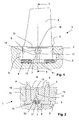
- FIG. 1 shows a section in the rotor longitudinal direction through a rotor-end 1 according to the invention after installation in a compressor rotor.
- FIG. 2 shows a section in the circumferential direction along the line II - II from FIG. 1.
- FIG. 1 and FIG. 2 represents a partial section of a rotating rotor groove 3 of a compressor stage.
- the groove 3 are already all upsetting blades and intermediate pieces (not shown in this section) and the two closing blades 4, 4 mounted.
- the closing blades 4, 4 differ from the regular compression blades only in that the bulge on the inlet and outlet side is removed.
- the axially separated rotor closure has two end halves 9, 9, a first side half 5, a second side half 6, a bracket 8 and a wedge 7 made of chrome nickel steel.
- the package formed from the shims 5, 6 and the wedge 7, the clamp 8 and the end halves 9, 9 together have a comparable mass with an intermediate piece.
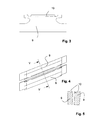
- FIG. 3 shows a side view of a closure half 9, 9 according to the invention
- FIG. 4 shows a plan view of the two closure halves
- Fig. 5 shows a section along the line V -V of Figure 4.
- the two end halves 9, 9 are made in the present embodiment of a chromium-nickel-molybdenum alloy.
- the outer contour of the closing half 9 is designed so that it corresponds to the T-shaped cross-section of the circumferential groove 3 of the rotor disk 2.
- the elongated webs or lobes 10 are shown at the top of the end half 9, which are crimped at the end of assembly.
- FIG. 6 shows a side view of two supplement halves 5, 6 according to the invention, which in the present exemplary embodiment are made of a chromium-nickel-molybdenum alloy.
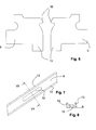
- the bracket 8 is the component which absorbs the axial forces in the present invention and thus provides for the relief of the rotor groove.
- the bracket 8 is a plan view of a substantially rectangular metal profile with a central longitudinal slot or a central elongated recess 12.
- the bracket 8 has a U-profile in cross-section. Through the recess 12 and the U-legs 13, the clip with the end halves 9.9 and the supplement halves 5, 6 is engaged. Together with the wedge 7 so a fastening dressing is formed.
- Fig. 7 shows a detail plan view of a clip 8 according to the invention.
- Fig. 8 shows a cross section through the clip 8 along the line VIII - VIII from Figure 7.
- the bracket 8 is made in the present embodiment of a chromium molybdenum alloy.
- a circumferential groove 3 is inserted with a substantially T-shaped cross-section in a rotor disk 2.
- upsetting blades and intermediate pieces 15 are alternately mounted until the two closing blades 4 are mounted, between which no regular intermediate piece 15 can be mounted because of the small space in the residual gap.
- the wedges 7 are spread in the shims 18, 18, which together form a heart shape in side view.
- the sheath tabs 16, 16 on the heart shape are then, as shown in Figure 10, driven over the spread wedge 7.
Landscapes
- Engineering & Computer Science (AREA)
- Mechanical Engineering (AREA)
- General Engineering & Computer Science (AREA)
- Turbine Rotor Nozzle Sealing (AREA)
Applications Claiming Priority (1)
| Application Number | Priority Date | Filing Date | Title |
|---|---|---|---|
| CH3222005 | 2005-02-23 |
Publications (3)
| Publication Number | Publication Date |
|---|---|
| EP1698758A2 true EP1698758A2 (fr) | 2006-09-06 |
| EP1698758A3 EP1698758A3 (fr) | 2013-03-27 |
| EP1698758B1 EP1698758B1 (fr) | 2015-11-11 |
Family
ID=34974750
Family Applications (1)
| Application Number | Title | Priority Date | Filing Date |
|---|---|---|---|
| EP06110011.1A Active EP1698758B1 (fr) | 2005-02-23 | 2006-02-16 | Fermeture de rotor à fente axiale |
Country Status (2)
| Country | Link |
|---|---|
| US (1) | US7338258B2 (fr) |
| EP (1) | EP1698758B1 (fr) |
Cited By (4)
| Publication number | Priority date | Publication date | Assignee | Title |
|---|---|---|---|---|
| EP2045444A1 (fr) | 2007-10-01 | 2009-04-08 | ALSTOM Technology Ltd | Aube de rotor, procédé de fabrication d'une aube de rotor, et compresseur avec une telle aube |
| CH702204A1 (de) * | 2009-11-10 | 2011-05-13 | Alstom Technology Ltd | Rotor für eine axial durchströmte turbomaschine sowie gasturbine für solchen rotor. |
| EP3159483A1 (fr) * | 2015-10-22 | 2017-04-26 | Siemens Aktiengesellschaft | Dispositif de fixation d'aubes mobiles d'une turbomachine thermique |
| CN108791817A (zh) * | 2018-06-26 | 2018-11-13 | 李荣旭 | 一种具有低阻力性能的飞行器螺旋桨及其组装方法 |
Families Citing this family (4)
| Publication number | Priority date | Publication date | Assignee | Title |
|---|---|---|---|---|
| US8162615B2 (en) * | 2009-03-17 | 2012-04-24 | United Technologies Corporation | Split disk assembly for a gas turbine engine |
| US8545184B2 (en) * | 2010-01-05 | 2013-10-01 | General Electric Company | Locking spacer assembly |
| US8517688B2 (en) * | 2010-09-21 | 2013-08-27 | General Electric Company | Rotor assembly for use in turbine engines and methods for assembling same |
| US10465699B2 (en) * | 2017-01-26 | 2019-11-05 | DOOSAN Heavy Industries Construction Co., LTD | Compressor blade locking mechanism in disk with tangential groove |
Citations (4)
| Publication number | Priority date | Publication date | Assignee | Title |
|---|---|---|---|---|
| CH349624A (de) * | 1957-03-05 | 1960-10-31 | Oerlikon Maschf | Axiale Strömungsmaschine |
| DE1751819B1 (de) * | 1968-07-26 | 1971-01-21 | Sulzer Ag | Läufer für Str¦mungsmaschinen |
| EP1215367A2 (fr) * | 2000-12-16 | 2002-06-19 | ALSTOM Power N.V. | Dispositif de fixation des aubes de turbomachine |
| EP1457642A2 (fr) * | 2003-03-11 | 2004-09-15 | Alstom Technology Ltd | Dispositif de fixation d'aubes sur un rotor |
Family Cites Families (5)
| Publication number | Priority date | Publication date | Assignee | Title |
|---|---|---|---|---|
| NL56668C (fr) | 1940-06-12 | |||
| US2406703A (en) * | 1944-06-08 | 1946-08-27 | Allis Chalmers Mfg Co | Turbine blade locking apparatus |
| FR974989A (fr) | 1948-09-17 | 1951-02-28 | Verrou pour l'aubage des rotors en forme de tambour de compresseurs axiaux et de turbines à vapeur ou à gaz | |
| US3252687A (en) * | 1965-02-01 | 1966-05-24 | Gen Motors Corp | Rotor blade locking |
| EP1028231B1 (fr) | 1999-02-12 | 2003-09-03 | ALSTOM (Switzerland) Ltd | Fixation d'aubes de rotor d'une turbomachine |
-
2006
- 2006-02-16 EP EP06110011.1A patent/EP1698758B1/fr active Active
- 2006-02-17 US US11/276,186 patent/US7338258B2/en active Active
Patent Citations (4)
| Publication number | Priority date | Publication date | Assignee | Title |
|---|---|---|---|---|
| CH349624A (de) * | 1957-03-05 | 1960-10-31 | Oerlikon Maschf | Axiale Strömungsmaschine |
| DE1751819B1 (de) * | 1968-07-26 | 1971-01-21 | Sulzer Ag | Läufer für Str¦mungsmaschinen |
| EP1215367A2 (fr) * | 2000-12-16 | 2002-06-19 | ALSTOM Power N.V. | Dispositif de fixation des aubes de turbomachine |
| EP1457642A2 (fr) * | 2003-03-11 | 2004-09-15 | Alstom Technology Ltd | Dispositif de fixation d'aubes sur un rotor |
Cited By (6)
| Publication number | Priority date | Publication date | Assignee | Title |
|---|---|---|---|---|
| EP2045444A1 (fr) | 2007-10-01 | 2009-04-08 | ALSTOM Technology Ltd | Aube de rotor, procédé de fabrication d'une aube de rotor, et compresseur avec une telle aube |
| US8257047B2 (en) | 2007-10-01 | 2012-09-04 | Alstom Technology Ltd. | Rotor blade, method for producing a rotor blade, and compressor with a rotor blade |
| CH702204A1 (de) * | 2009-11-10 | 2011-05-13 | Alstom Technology Ltd | Rotor für eine axial durchströmte turbomaschine sowie gasturbine für solchen rotor. |
| EP3159483A1 (fr) * | 2015-10-22 | 2017-04-26 | Siemens Aktiengesellschaft | Dispositif de fixation d'aubes mobiles d'une turbomachine thermique |
| CN108791817A (zh) * | 2018-06-26 | 2018-11-13 | 李荣旭 | 一种具有低阻力性能的飞行器螺旋桨及其组装方法 |
| CN108791817B (zh) * | 2018-06-26 | 2021-07-20 | 深圳市飞翼创新有限公司 | 一种具有低阻力性能的飞行器螺旋桨及其组装方法 |
Also Published As
| Publication number | Publication date |
|---|---|
| EP1698758A3 (fr) | 2013-03-27 |
| US20060188373A1 (en) | 2006-08-24 |
| US7338258B2 (en) | 2008-03-04 |
| EP1698758B1 (fr) | 2015-11-11 |
Similar Documents
| Publication | Publication Date | Title |
|---|---|---|
| EP1698758B1 (fr) | Fermeture de rotor à fente axiale | |
| EP2414641B1 (fr) | Rotor de turbomachine axiale doté d'un disque d'étanchéité | |
| EP1457640B1 (fr) | Redresseur tubulaire de vortex pour turbine à gaz et sa structure de support | |
| EP2723991B1 (fr) | Agencement d'aubes | |
| EP1714006A1 (fr) | Systeme amortisseur pour aubes directrices | |
| EP2478186B1 (fr) | Rotor de turbomachine | |
| EP1483482A1 (fr) | Fixation d'une aube directrice dans le canal d'ecoulement d'une turbine a gaz d'avion | |
| DE19828817C2 (de) | Rotor für eine Turbomaschine | |
| EP3999717B1 (fr) | Élément intermédiaire pour une connexion aube-disque de rotor pour le rotor d'une turbomachine, rotor pour une turbomachine et turbomachine | |
| CH704212A1 (de) | Axialkompressor. | |
| DE2002469C3 (de) | Laufschaufelbefestigung in einer schwalbenschwanzförmigen Umfangsnut eines Läufers axial durchströmter Strömungsmaschinen, insbesondere Gasturbinenstrahltriebwerke | |
| EP1457642B1 (fr) | Dispositif de fixation d'aubes sur un rotor | |
| EP1413712A1 (fr) | Virole pour une turbine avec joint d'extrémité | |
| EP2960555A1 (fr) | Système de joint à brosse pour sceller un intervalle entre les éléments d'une turbomachine qui peuvent être déplacés les uns par rapport aux autres | |
| DE602005005254T2 (de) | Rotorscheibe einer Turbomaschine | |
| CH714651A2 (de) | Verschalung eines Turboladers und Turbolader. | |
| EP3121385B1 (fr) | Dispositif de rotor d'un réacteur d'avion avec un disposiitf d'amortissement entre des pales | |
| WO2013020643A1 (fr) | Élément de construction | |
| EP3379037B1 (fr) | Étanchéité sur une bague intérieure d'une couronne d'aubes directrices | |
| EP3309359B1 (fr) | Ensemble d'aubes mobiles pour un moteur à turbine à gaz | |
| EP3194725B1 (fr) | Rotor, compresseur axial, procédé de montage | |
| EP1698759B1 (fr) | Fermeture de rotor | |
| DE102009007664A1 (de) | Abdichtvorrichtung an dem Schaufelschaft einer Rotorstufe einer axialen Strömungsmaschine | |
| DE19823157A1 (de) | Einrichtung zur Befestigung der Laufschaufeln axial durchströmter Turbomaschinen | |
| EP2404038A1 (fr) | Rotor à aubage intégral et procédé de fabrication d'un rotor à aubage intégral |
Legal Events
| Date | Code | Title | Description |
|---|---|---|---|
| PUAI | Public reference made under article 153(3) epc to a published international application that has entered the european phase |
Free format text: ORIGINAL CODE: 0009012 |
|
| AK | Designated contracting states |
Kind code of ref document: A2 Designated state(s): AT BE BG CH CY CZ DE DK EE ES FI FR GB GR HU IE IS IT LI LT LU LV MC NL PL PT RO SE SI SK TR |
|
| AX | Request for extension of the european patent |
Extension state: AL BA HR MK YU |
|
| REG | Reference to a national code |
Ref country code: DE Ref legal event code: R079 Ref document number: 502006014631 Country of ref document: DE Free format text: PREVIOUS MAIN CLASS: F01D0005300000 Ipc: F01D0005320000 |
|
| PUAL | Search report despatched |
Free format text: ORIGINAL CODE: 0009013 |
|
| AK | Designated contracting states |
Kind code of ref document: A3 Designated state(s): AT BE BG CH CY CZ DE DK EE ES FI FR GB GR HU IE IS IT LI LT LU LV MC NL PL PT RO SE SI SK TR |
|
| AX | Request for extension of the european patent |
Extension state: AL BA HR MK YU |
|
| RIC1 | Information provided on ipc code assigned before grant |
Ipc: F01D 5/32 20060101AFI20130215BHEP Ipc: F01D 5/30 20060101ALI20130215BHEP |
|
| 17P | Request for examination filed |
Effective date: 20130918 |
|
| RBV | Designated contracting states (corrected) |
Designated state(s): AT BE BG CH CY CZ DE DK EE ES FI FR GB GR HU IE IS IT LI LT LU LV MC NL PL PT RO SE SI SK TR |
|
| AKX | Designation fees paid |
Designated state(s): AT BE BG CH CY CZ DE DK EE ES FI FR GB GR HU IE IS IT LI LT LU LV MC NL PL PT RO SE SI SK TR |
|
| GRAP | Despatch of communication of intention to grant a patent |
Free format text: ORIGINAL CODE: EPIDOSNIGR1 |
|
| INTG | Intention to grant announced |
Effective date: 20150612 |
|
| GRAS | Grant fee paid |
Free format text: ORIGINAL CODE: EPIDOSNIGR3 |
|
| GRAA | (expected) grant |
Free format text: ORIGINAL CODE: 0009210 |
|
| AK | Designated contracting states |
Kind code of ref document: B1 Designated state(s): AT BE BG CH CY CZ DE DK EE ES FI FR GB GR HU IE IS IT LI LT LU LV MC NL PL PT RO SE SI SK TR |
|
| REG | Reference to a national code |
Ref country code: GB Ref legal event code: FG4D Free format text: NOT ENGLISH Ref country code: DE Ref legal event code: R081 Ref document number: 502006014631 Country of ref document: DE Owner name: GENERAL ELECTRIC TECHNOLOGY GMBH, CH Free format text: FORMER OWNER: ALSTOM TECHNOLOGY LTD., BADEN, CH |
|
| REG | Reference to a national code |
Ref country code: CH Ref legal event code: EP |
|
| REG | Reference to a national code |
Ref country code: IE Ref legal event code: FG4D Free format text: LANGUAGE OF EP DOCUMENT: GERMAN |
|
| REG | Reference to a national code |
Ref country code: AT Ref legal event code: REF Ref document number: 760571 Country of ref document: AT Kind code of ref document: T Effective date: 20151215 |
|
| REG | Reference to a national code |
Ref country code: DE Ref legal event code: R096 Ref document number: 502006014631 Country of ref document: DE |
|
| REG | Reference to a national code |
Ref country code: LT Ref legal event code: MG4D |
|
| REG | Reference to a national code |
Ref country code: NL Ref legal event code: MP Effective date: 20160211 |
|
| PG25 | Lapsed in a contracting state [announced via postgrant information from national office to epo] |
Ref country code: ES Free format text: LAPSE BECAUSE OF FAILURE TO SUBMIT A TRANSLATION OF THE DESCRIPTION OR TO PAY THE FEE WITHIN THE PRESCRIBED TIME-LIMIT Effective date: 20151111 Ref country code: NL Free format text: LAPSE BECAUSE OF FAILURE TO SUBMIT A TRANSLATION OF THE DESCRIPTION OR TO PAY THE FEE WITHIN THE PRESCRIBED TIME-LIMIT Effective date: 20151111 Ref country code: IS Free format text: LAPSE BECAUSE OF FAILURE TO SUBMIT A TRANSLATION OF THE DESCRIPTION OR TO PAY THE FEE WITHIN THE PRESCRIBED TIME-LIMIT Effective date: 20160311 Ref country code: LT Free format text: LAPSE BECAUSE OF FAILURE TO SUBMIT A TRANSLATION OF THE DESCRIPTION OR TO PAY THE FEE WITHIN THE PRESCRIBED TIME-LIMIT Effective date: 20151111 |
|
| PG25 | Lapsed in a contracting state [announced via postgrant information from national office to epo] |
Ref country code: PL Free format text: LAPSE BECAUSE OF FAILURE TO SUBMIT A TRANSLATION OF THE DESCRIPTION OR TO PAY THE FEE WITHIN THE PRESCRIBED TIME-LIMIT Effective date: 20151111 Ref country code: PT Free format text: LAPSE BECAUSE OF FAILURE TO SUBMIT A TRANSLATION OF THE DESCRIPTION OR TO PAY THE FEE WITHIN THE PRESCRIBED TIME-LIMIT Effective date: 20160311 Ref country code: FI Free format text: LAPSE BECAUSE OF FAILURE TO SUBMIT A TRANSLATION OF THE DESCRIPTION OR TO PAY THE FEE WITHIN THE PRESCRIBED TIME-LIMIT Effective date: 20151111 Ref country code: LV Free format text: LAPSE BECAUSE OF FAILURE TO SUBMIT A TRANSLATION OF THE DESCRIPTION OR TO PAY THE FEE WITHIN THE PRESCRIBED TIME-LIMIT Effective date: 20151111 Ref country code: SE Free format text: LAPSE BECAUSE OF FAILURE TO SUBMIT A TRANSLATION OF THE DESCRIPTION OR TO PAY THE FEE WITHIN THE PRESCRIBED TIME-LIMIT Effective date: 20151111 Ref country code: GR Free format text: LAPSE BECAUSE OF FAILURE TO SUBMIT A TRANSLATION OF THE DESCRIPTION OR TO PAY THE FEE WITHIN THE PRESCRIBED TIME-LIMIT Effective date: 20160212 Ref country code: BE Free format text: LAPSE BECAUSE OF NON-PAYMENT OF DUE FEES Effective date: 20160229 |
|
| PG25 | Lapsed in a contracting state [announced via postgrant information from national office to epo] |
Ref country code: CZ Free format text: LAPSE BECAUSE OF FAILURE TO SUBMIT A TRANSLATION OF THE DESCRIPTION OR TO PAY THE FEE WITHIN THE PRESCRIBED TIME-LIMIT Effective date: 20151111 |
|
| REG | Reference to a national code |
Ref country code: DE Ref legal event code: R097 Ref document number: 502006014631 Country of ref document: DE |
|
| RAP2 | Party data changed (patent owner data changed or rights of a patent transferred) |
Owner name: GENERAL ELECTRIC TECHNOLOGY GMBH |
|
| PG25 | Lapsed in a contracting state [announced via postgrant information from national office to epo] |
Ref country code: DK Free format text: LAPSE BECAUSE OF FAILURE TO SUBMIT A TRANSLATION OF THE DESCRIPTION OR TO PAY THE FEE WITHIN THE PRESCRIBED TIME-LIMIT Effective date: 20151111 Ref country code: RO Free format text: LAPSE BECAUSE OF FAILURE TO SUBMIT A TRANSLATION OF THE DESCRIPTION OR TO PAY THE FEE WITHIN THE PRESCRIBED TIME-LIMIT Effective date: 20151111 Ref country code: EE Free format text: LAPSE BECAUSE OF FAILURE TO SUBMIT A TRANSLATION OF THE DESCRIPTION OR TO PAY THE FEE WITHIN THE PRESCRIBED TIME-LIMIT Effective date: 20151111 Ref country code: SK Free format text: LAPSE BECAUSE OF FAILURE TO SUBMIT A TRANSLATION OF THE DESCRIPTION OR TO PAY THE FEE WITHIN THE PRESCRIBED TIME-LIMIT Effective date: 20151111 |
|
| PLBE | No opposition filed within time limit |
Free format text: ORIGINAL CODE: 0009261 |
|
| STAA | Information on the status of an ep patent application or granted ep patent |
Free format text: STATUS: NO OPPOSITION FILED WITHIN TIME LIMIT |
|
| PG25 | Lapsed in a contracting state [announced via postgrant information from national office to epo] |
Ref country code: LU Free format text: LAPSE BECAUSE OF FAILURE TO SUBMIT A TRANSLATION OF THE DESCRIPTION OR TO PAY THE FEE WITHIN THE PRESCRIBED TIME-LIMIT Effective date: 20160216 Ref country code: MC Free format text: LAPSE BECAUSE OF FAILURE TO SUBMIT A TRANSLATION OF THE DESCRIPTION OR TO PAY THE FEE WITHIN THE PRESCRIBED TIME-LIMIT Effective date: 20151111 |
|
| REG | Reference to a national code |
Ref country code: CH Ref legal event code: PL |
|
| REG | Reference to a national code |
Ref country code: DE Ref legal event code: R082 Ref document number: 502006014631 Country of ref document: DE Representative=s name: RUEGER | ABEL PATENT- UND RECHTSANWAELTE, DE Ref country code: DE Ref legal event code: R082 Ref document number: 502006014631 Country of ref document: DE Representative=s name: RUEGER ABEL PATENTANWAELTE PARTGMBB, DE Ref country code: DE Ref legal event code: R082 Ref document number: 502006014631 Country of ref document: DE Representative=s name: RUEGER, BARTHELT & ABEL, DE Ref country code: DE Ref legal event code: R081 Ref document number: 502006014631 Country of ref document: DE Owner name: GENERAL ELECTRIC TECHNOLOGY GMBH, CH Free format text: FORMER OWNER: ALSTOM TECHNOLOGY LTD., BADEN, CH Ref country code: DE Ref legal event code: R082 Ref document number: 502006014631 Country of ref document: DE Representative=s name: RUEGER ABEL PATENT- UND RECHTSANWAELTE, DE |
|
| 26N | No opposition filed |
Effective date: 20160812 |
|
| PG25 | Lapsed in a contracting state [announced via postgrant information from national office to epo] |
Ref country code: CH Free format text: LAPSE BECAUSE OF NON-PAYMENT OF DUE FEES Effective date: 20160229 Ref country code: LI Free format text: LAPSE BECAUSE OF NON-PAYMENT OF DUE FEES Effective date: 20160229 |
|
| REG | Reference to a national code |
Ref country code: FR Ref legal event code: ST Effective date: 20161028 |
|
| PG25 | Lapsed in a contracting state [announced via postgrant information from national office to epo] |
Ref country code: SI Free format text: LAPSE BECAUSE OF FAILURE TO SUBMIT A TRANSLATION OF THE DESCRIPTION OR TO PAY THE FEE WITHIN THE PRESCRIBED TIME-LIMIT Effective date: 20151111 |
|
| REG | Reference to a national code |
Ref country code: IE Ref legal event code: MM4A |
|
| PG25 | Lapsed in a contracting state [announced via postgrant information from national office to epo] |
Ref country code: FR Free format text: LAPSE BECAUSE OF NON-PAYMENT OF DUE FEES Effective date: 20160229 Ref country code: IE Free format text: LAPSE BECAUSE OF NON-PAYMENT OF DUE FEES Effective date: 20160216 |
|
| REG | Reference to a national code |
Ref country code: AT Ref legal event code: MM01 Ref document number: 760571 Country of ref document: AT Kind code of ref document: T Effective date: 20160216 |
|
| PG25 | Lapsed in a contracting state [announced via postgrant information from national office to epo] |
Ref country code: AT Free format text: LAPSE BECAUSE OF NON-PAYMENT OF DUE FEES Effective date: 20160216 |
|
| PG25 | Lapsed in a contracting state [announced via postgrant information from national office to epo] |
Ref country code: HU Free format text: LAPSE BECAUSE OF FAILURE TO SUBMIT A TRANSLATION OF THE DESCRIPTION OR TO PAY THE FEE WITHIN THE PRESCRIBED TIME-LIMIT; INVALID AB INITIO Effective date: 20060216 Ref country code: CY Free format text: LAPSE BECAUSE OF FAILURE TO SUBMIT A TRANSLATION OF THE DESCRIPTION OR TO PAY THE FEE WITHIN THE PRESCRIBED TIME-LIMIT Effective date: 20151111 |
|
| PG25 | Lapsed in a contracting state [announced via postgrant information from national office to epo] |
Ref country code: TR Free format text: LAPSE BECAUSE OF FAILURE TO SUBMIT A TRANSLATION OF THE DESCRIPTION OR TO PAY THE FEE WITHIN THE PRESCRIBED TIME-LIMIT Effective date: 20151111 |
|
| PG25 | Lapsed in a contracting state [announced via postgrant information from national office to epo] |
Ref country code: BG Free format text: LAPSE BECAUSE OF FAILURE TO SUBMIT A TRANSLATION OF THE DESCRIPTION OR TO PAY THE FEE WITHIN THE PRESCRIBED TIME-LIMIT Effective date: 20151111 |
|
| PGFP | Annual fee paid to national office [announced via postgrant information from national office to epo] |
Ref country code: IT Payment date: 20230120 Year of fee payment: 18 |
|
| P01 | Opt-out of the competence of the unified patent court (upc) registered |
Effective date: 20230522 |
|
| PGFP | Annual fee paid to national office [announced via postgrant information from national office to epo] |
Ref country code: DE Payment date: 20240123 Year of fee payment: 19 Ref country code: GB Payment date: 20240123 Year of fee payment: 19 |