EP1698607A1 - Verfahren zur Adsorberregenerierung - Google Patents
Verfahren zur Adsorberregenerierung Download PDFInfo
- Publication number
- EP1698607A1 EP1698607A1 EP06004017A EP06004017A EP1698607A1 EP 1698607 A1 EP1698607 A1 EP 1698607A1 EP 06004017 A EP06004017 A EP 06004017A EP 06004017 A EP06004017 A EP 06004017A EP 1698607 A1 EP1698607 A1 EP 1698607A1
- Authority
- EP
- European Patent Office
- Prior art keywords
- gas
- adsorber
- regeneration
- synthesis gas
- synthesis
- Prior art date
- Legal status (The legal status is an assumption and is not a legal conclusion. Google has not performed a legal analysis and makes no representation as to the accuracy of the status listed.)
- Granted
Links
Images


Classifications
-
- F—MECHANICAL ENGINEERING; LIGHTING; HEATING; WEAPONS; BLASTING
- F25—REFRIGERATION OR COOLING; COMBINED HEATING AND REFRIGERATION SYSTEMS; HEAT PUMP SYSTEMS; MANUFACTURE OR STORAGE OF ICE; LIQUEFACTION SOLIDIFICATION OF GASES
- F25J—LIQUEFACTION, SOLIDIFICATION OR SEPARATION OF GASES OR GASEOUS OR LIQUEFIED GASEOUS MIXTURES BY PRESSURE AND COLD TREATMENT OR BY BRINGING THEM INTO THE SUPERCRITICAL STATE
- F25J3/00—Processes or apparatus for separating the constituents of gaseous or liquefied gaseous mixtures involving the use of liquefaction or solidification
- F25J3/02—Processes or apparatus for separating the constituents of gaseous or liquefied gaseous mixtures involving the use of liquefaction or solidification by rectification, i.e. by continuous interchange of heat and material between a vapour stream and a liquid stream
- F25J3/0204—Processes or apparatus for separating the constituents of gaseous or liquefied gaseous mixtures involving the use of liquefaction or solidification by rectification, i.e. by continuous interchange of heat and material between a vapour stream and a liquid stream characterised by the feed stream
- F25J3/0223—H2/CO mixtures, i.e. synthesis gas; Water gas or shifted synthesis gas
-
- B—PERFORMING OPERATIONS; TRANSPORTING
- B01—PHYSICAL OR CHEMICAL PROCESSES OR APPARATUS IN GENERAL
- B01D—SEPARATION
- B01D53/00—Separation of gases or vapours; Recovering vapours of volatile solvents from gases; Chemical or biological purification of waste gases, e.g. engine exhaust gases, smoke, fumes, flue gases, aerosols
- B01D53/02—Separation of gases or vapours; Recovering vapours of volatile solvents from gases; Chemical or biological purification of waste gases, e.g. engine exhaust gases, smoke, fumes, flue gases, aerosols by adsorption, e.g. preparative gas chromatography
- B01D53/04—Separation of gases or vapours; Recovering vapours of volatile solvents from gases; Chemical or biological purification of waste gases, e.g. engine exhaust gases, smoke, fumes, flue gases, aerosols by adsorption, e.g. preparative gas chromatography with stationary adsorbents
-
- B—PERFORMING OPERATIONS; TRANSPORTING
- B01—PHYSICAL OR CHEMICAL PROCESSES OR APPARATUS IN GENERAL
- B01D—SEPARATION
- B01D53/00—Separation of gases or vapours; Recovering vapours of volatile solvents from gases; Chemical or biological purification of waste gases, e.g. engine exhaust gases, smoke, fumes, flue gases, aerosols
- B01D53/14—Separation of gases or vapours; Recovering vapours of volatile solvents from gases; Chemical or biological purification of waste gases, e.g. engine exhaust gases, smoke, fumes, flue gases, aerosols by absorption
- B01D53/1456—Removing acid components
- B01D53/1475—Removing carbon dioxide
-
- C—CHEMISTRY; METALLURGY
- C01—INORGANIC CHEMISTRY
- C01B—NON-METALLIC ELEMENTS; COMPOUNDS THEREOF; METALLOIDS OR COMPOUNDS THEREOF NOT COVERED BY SUBCLASS C01C
- C01B3/00—Hydrogen; Gaseous mixtures containing hydrogen; Separation of hydrogen from mixtures containing it; Purification of hydrogen; Reversible storage of hydrogen
- C01B3/50—Separation of hydrogen or hydrogen-containing gases from gaseous mixtures, e.g. purification
- C01B3/506—Separation of hydrogen or hydrogen-containing gases from gaseous mixtures, e.g. purification at low temperatures
-
- C—CHEMISTRY; METALLURGY
- C01—INORGANIC CHEMISTRY
- C01B—NON-METALLIC ELEMENTS; COMPOUNDS THEREOF; METALLOIDS OR COMPOUNDS THEREOF NOT COVERED BY SUBCLASS C01C
- C01B3/00—Hydrogen; Gaseous mixtures containing hydrogen; Separation of hydrogen from mixtures containing it; Purification of hydrogen; Reversible storage of hydrogen
- C01B3/50—Separation of hydrogen or hydrogen-containing gases from gaseous mixtures, e.g. purification
- C01B3/56—Separation of hydrogen or hydrogen-containing gases from gaseous mixtures, e.g. purification by contacting with solids; Regeneration of used solids
-
- F—MECHANICAL ENGINEERING; LIGHTING; HEATING; WEAPONS; BLASTING
- F25—REFRIGERATION OR COOLING; COMBINED HEATING AND REFRIGERATION SYSTEMS; HEAT PUMP SYSTEMS; MANUFACTURE OR STORAGE OF ICE; LIQUEFACTION SOLIDIFICATION OF GASES
- F25J—LIQUEFACTION, SOLIDIFICATION OR SEPARATION OF GASES OR GASEOUS OR LIQUEFIED GASEOUS MIXTURES BY PRESSURE AND COLD TREATMENT OR BY BRINGING THEM INTO THE SUPERCRITICAL STATE
- F25J3/00—Processes or apparatus for separating the constituents of gaseous or liquefied gaseous mixtures involving the use of liquefaction or solidification
- F25J3/02—Processes or apparatus for separating the constituents of gaseous or liquefied gaseous mixtures involving the use of liquefaction or solidification by rectification, i.e. by continuous interchange of heat and material between a vapour stream and a liquid stream
- F25J3/0228—Processes or apparatus for separating the constituents of gaseous or liquefied gaseous mixtures involving the use of liquefaction or solidification by rectification, i.e. by continuous interchange of heat and material between a vapour stream and a liquid stream characterised by the separated product stream
- F25J3/0252—Processes or apparatus for separating the constituents of gaseous or liquefied gaseous mixtures involving the use of liquefaction or solidification by rectification, i.e. by continuous interchange of heat and material between a vapour stream and a liquid stream characterised by the separated product stream separation of hydrogen
-
- F—MECHANICAL ENGINEERING; LIGHTING; HEATING; WEAPONS; BLASTING
- F25—REFRIGERATION OR COOLING; COMBINED HEATING AND REFRIGERATION SYSTEMS; HEAT PUMP SYSTEMS; MANUFACTURE OR STORAGE OF ICE; LIQUEFACTION SOLIDIFICATION OF GASES
- F25J—LIQUEFACTION, SOLIDIFICATION OR SEPARATION OF GASES OR GASEOUS OR LIQUEFIED GASEOUS MIXTURES BY PRESSURE AND COLD TREATMENT OR BY BRINGING THEM INTO THE SUPERCRITICAL STATE
- F25J3/00—Processes or apparatus for separating the constituents of gaseous or liquefied gaseous mixtures involving the use of liquefaction or solidification
- F25J3/02—Processes or apparatus for separating the constituents of gaseous or liquefied gaseous mixtures involving the use of liquefaction or solidification by rectification, i.e. by continuous interchange of heat and material between a vapour stream and a liquid stream
- F25J3/0228—Processes or apparatus for separating the constituents of gaseous or liquefied gaseous mixtures involving the use of liquefaction or solidification by rectification, i.e. by continuous interchange of heat and material between a vapour stream and a liquid stream characterised by the separated product stream
- F25J3/0261—Processes or apparatus for separating the constituents of gaseous or liquefied gaseous mixtures involving the use of liquefaction or solidification by rectification, i.e. by continuous interchange of heat and material between a vapour stream and a liquid stream characterised by the separated product stream separation of carbon monoxide
-
- F—MECHANICAL ENGINEERING; LIGHTING; HEATING; WEAPONS; BLASTING
- F25—REFRIGERATION OR COOLING; COMBINED HEATING AND REFRIGERATION SYSTEMS; HEAT PUMP SYSTEMS; MANUFACTURE OR STORAGE OF ICE; LIQUEFACTION SOLIDIFICATION OF GASES
- F25J—LIQUEFACTION, SOLIDIFICATION OR SEPARATION OF GASES OR GASEOUS OR LIQUEFIED GASEOUS MIXTURES BY PRESSURE AND COLD TREATMENT OR BY BRINGING THEM INTO THE SUPERCRITICAL STATE
- F25J3/00—Processes or apparatus for separating the constituents of gaseous or liquefied gaseous mixtures involving the use of liquefaction or solidification
- F25J3/02—Processes or apparatus for separating the constituents of gaseous or liquefied gaseous mixtures involving the use of liquefaction or solidification by rectification, i.e. by continuous interchange of heat and material between a vapour stream and a liquid stream
- F25J3/0228—Processes or apparatus for separating the constituents of gaseous or liquefied gaseous mixtures involving the use of liquefaction or solidification by rectification, i.e. by continuous interchange of heat and material between a vapour stream and a liquid stream characterised by the separated product stream
- F25J3/0271—Processes or apparatus for separating the constituents of gaseous or liquefied gaseous mixtures involving the use of liquefaction or solidification by rectification, i.e. by continuous interchange of heat and material between a vapour stream and a liquid stream characterised by the separated product stream separation of H2/CO mixtures, i.e. of synthesis gas
-
- B—PERFORMING OPERATIONS; TRANSPORTING
- B01—PHYSICAL OR CHEMICAL PROCESSES OR APPARATUS IN GENERAL
- B01D—SEPARATION
- B01D2259/00—Type of treatment
- B01D2259/40—Further details for adsorption processes and devices
- B01D2259/40083—Regeneration of adsorbents in processes other than pressure or temperature swing adsorption
-
- B—PERFORMING OPERATIONS; TRANSPORTING
- B01—PHYSICAL OR CHEMICAL PROCESSES OR APPARATUS IN GENERAL
- B01D—SEPARATION
- B01D2259/00—Type of treatment
- B01D2259/40—Further details for adsorption processes and devices
- B01D2259/416—Further details for adsorption processes and devices involving cryogenic temperature treatment
-
- C—CHEMISTRY; METALLURGY
- C01—INORGANIC CHEMISTRY
- C01B—NON-METALLIC ELEMENTS; COMPOUNDS THEREOF; METALLOIDS OR COMPOUNDS THEREOF NOT COVERED BY SUBCLASS C01C
- C01B2203/00—Integrated processes for the production of hydrogen or synthesis gas
- C01B2203/04—Integrated processes for the production of hydrogen or synthesis gas containing a purification step for the hydrogen or the synthesis gas
- C01B2203/046—Purification by cryogenic separation
-
- C—CHEMISTRY; METALLURGY
- C01—INORGANIC CHEMISTRY
- C01B—NON-METALLIC ELEMENTS; COMPOUNDS THEREOF; METALLOIDS OR COMPOUNDS THEREOF NOT COVERED BY SUBCLASS C01C
- C01B2203/00—Integrated processes for the production of hydrogen or synthesis gas
- C01B2203/04—Integrated processes for the production of hydrogen or synthesis gas containing a purification step for the hydrogen or the synthesis gas
- C01B2203/0465—Composition of the impurity
- C01B2203/047—Composition of the impurity the impurity being carbon monoxide
-
- C—CHEMISTRY; METALLURGY
- C01—INORGANIC CHEMISTRY
- C01B—NON-METALLIC ELEMENTS; COMPOUNDS THEREOF; METALLOIDS OR COMPOUNDS THEREOF NOT COVERED BY SUBCLASS C01C
- C01B2203/00—Integrated processes for the production of hydrogen or synthesis gas
- C01B2203/04—Integrated processes for the production of hydrogen or synthesis gas containing a purification step for the hydrogen or the synthesis gas
- C01B2203/0465—Composition of the impurity
- C01B2203/0475—Composition of the impurity the impurity being carbon dioxide
-
- F—MECHANICAL ENGINEERING; LIGHTING; HEATING; WEAPONS; BLASTING
- F25—REFRIGERATION OR COOLING; COMBINED HEATING AND REFRIGERATION SYSTEMS; HEAT PUMP SYSTEMS; MANUFACTURE OR STORAGE OF ICE; LIQUEFACTION SOLIDIFICATION OF GASES
- F25J—LIQUEFACTION, SOLIDIFICATION OR SEPARATION OF GASES OR GASEOUS OR LIQUEFIED GASEOUS MIXTURES BY PRESSURE AND COLD TREATMENT OR BY BRINGING THEM INTO THE SUPERCRITICAL STATE
- F25J2205/00—Processes or apparatus using other separation and/or other processing means
- F25J2205/60—Processes or apparatus using other separation and/or other processing means using adsorption on solid adsorbents, e.g. by temperature-swing adsorption [TSA] at the hot or cold end
- F25J2205/66—Regenerating the adsorption vessel, e.g. kind of reactivation gas
-
- F—MECHANICAL ENGINEERING; LIGHTING; HEATING; WEAPONS; BLASTING
- F25—REFRIGERATION OR COOLING; COMBINED HEATING AND REFRIGERATION SYSTEMS; HEAT PUMP SYSTEMS; MANUFACTURE OR STORAGE OF ICE; LIQUEFACTION SOLIDIFICATION OF GASES
- F25J—LIQUEFACTION, SOLIDIFICATION OR SEPARATION OF GASES OR GASEOUS OR LIQUEFIED GASEOUS MIXTURES BY PRESSURE AND COLD TREATMENT OR BY BRINGING THEM INTO THE SUPERCRITICAL STATE
- F25J2210/00—Processes characterised by the type or other details of the feed stream
- F25J2210/06—Splitting of the feed stream, e.g. for treating or cooling in different ways
-
- F—MECHANICAL ENGINEERING; LIGHTING; HEATING; WEAPONS; BLASTING
- F25—REFRIGERATION OR COOLING; COMBINED HEATING AND REFRIGERATION SYSTEMS; HEAT PUMP SYSTEMS; MANUFACTURE OR STORAGE OF ICE; LIQUEFACTION SOLIDIFICATION OF GASES
- F25J—LIQUEFACTION, SOLIDIFICATION OR SEPARATION OF GASES OR GASEOUS OR LIQUEFIED GASEOUS MIXTURES BY PRESSURE AND COLD TREATMENT OR BY BRINGING THEM INTO THE SUPERCRITICAL STATE
- F25J2215/00—Processes characterised by the type or other details of the product stream
- F25J2215/02—Mixing or blending of fluids to yield a certain product
-
- F—MECHANICAL ENGINEERING; LIGHTING; HEATING; WEAPONS; BLASTING
- F25—REFRIGERATION OR COOLING; COMBINED HEATING AND REFRIGERATION SYSTEMS; HEAT PUMP SYSTEMS; MANUFACTURE OR STORAGE OF ICE; LIQUEFACTION SOLIDIFICATION OF GASES
- F25J—LIQUEFACTION, SOLIDIFICATION OR SEPARATION OF GASES OR GASEOUS OR LIQUEFIED GASEOUS MIXTURES BY PRESSURE AND COLD TREATMENT OR BY BRINGING THEM INTO THE SUPERCRITICAL STATE
- F25J2245/00—Processes or apparatus involving steps for recycling of process streams
- F25J2245/02—Recycle of a stream in general, e.g. a by-pass stream
-
- Y—GENERAL TAGGING OF NEW TECHNOLOGICAL DEVELOPMENTS; GENERAL TAGGING OF CROSS-SECTIONAL TECHNOLOGIES SPANNING OVER SEVERAL SECTIONS OF THE IPC; TECHNICAL SUBJECTS COVERED BY FORMER USPC CROSS-REFERENCE ART COLLECTIONS [XRACs] AND DIGESTS
- Y02—TECHNOLOGIES OR APPLICATIONS FOR MITIGATION OR ADAPTATION AGAINST CLIMATE CHANGE
- Y02C—CAPTURE, STORAGE, SEQUESTRATION OR DISPOSAL OF GREENHOUSE GASES [GHG]
- Y02C20/00—Capture or disposal of greenhouse gases
- Y02C20/40—Capture or disposal of greenhouse gases of CO2
-
- Y—GENERAL TAGGING OF NEW TECHNOLOGICAL DEVELOPMENTS; GENERAL TAGGING OF CROSS-SECTIONAL TECHNOLOGIES SPANNING OVER SEVERAL SECTIONS OF THE IPC; TECHNICAL SUBJECTS COVERED BY FORMER USPC CROSS-REFERENCE ART COLLECTIONS [XRACs] AND DIGESTS
- Y02—TECHNOLOGIES OR APPLICATIONS FOR MITIGATION OR ADAPTATION AGAINST CLIMATE CHANGE
- Y02P—CLIMATE CHANGE MITIGATION TECHNOLOGIES IN THE PRODUCTION OR PROCESSING OF GOODS
- Y02P20/00—Technologies relating to chemical industry
- Y02P20/151—Reduction of greenhouse gas [GHG] emissions, e.g. CO2
Definitions
- the invention relates to a method for regenerating the adsorber of an adsorber station, which is used for purifying a cryogenic gas separation unit of a synthesis gas plant incoming synthesis gas.
- Synthesis gas is a gas mixture consisting mainly of hydrogen (H 2 ), carbon monoxide (CO) and methane (CH 4 ), the exact composition of which depends on the manufacturing process and the raw materials used.
- syngas The main source of syngas is catalytic steam reforming, which breaks down natural gas, liquid gas or naphtha with the addition of water vapor.
- syngas can also by the partial oxidation of z.
- heavy oil or coal can be produced in an economical manner.
- the synthesis gas itself serves as a raw material for a large number of products, for which purpose it has to be purified and usually broken down into its main components.
- the majority of the CO thus obtained is used for the production of formic or acetic acid.
- Another major customer is in the polycarbonate industry, which requires the highest purity CO for the production of high purity phosgene.
- Synthesis gas-derived hydrogen is used in various hydrogenation processes.
- the condensation process and the methane scrubbing are used in industrial plants, in both cases being cryogenic processes.
- the prerequisite for the applicability of these processes is that the gas supplied to the cryogenic gas separation unit is free of water, methanol, carbon dioxide (CO 2 ) and other compounds which would lead to the formation of solids at the low temperatures occurring and thus to a transfer of the heat exchangers.
- the synthesis gas is therefore subjected to a multi-step pretreatment during which it z. B. undergoes a CO conversion and in a CO 2 scrubbing most of the undesirable Substances is cleaned. The remaining residues are removed by adsorption in a subsequent adsorber station.
- the adsorber stations used consist of at least two regenerable adsorbers, each containing at least one adsorbent bed (fixed bed of one or more suitable adsorbents).
- the pre-purified synthesis gas flows through the adsorber bed and thereby releases the undesirable substances contained in it (for example, CO 2 is still present at ⁇ 50 mol ppm) to the adsorbent or adsorbents.
- the switchover from the adsorber loaded with undesired substances to an unloaded adsorber of the adsorber station takes place.
- the loaded adsorber is then regenerated, ie purified from the previously adsorbed substances.
- the capacity of the adsorbent used is highly temperature dependent. In order to regenerate an adsorber, it is therefore first isolated from the synthesis gas stream and then flowed through with hot regeneration gas counter to the flow direction of the synthesis raw gas. The substances desorbed from the adsorber bed at the elevated temperature are discharged from the adsorber together with the regeneration gas. Depending on its composition, the regeneration gas loaded with the desorbed substances is treated differently.
- part of the H 2 fraction (H 2 content> about 90 mol%, under pressure) from the cryogenic gas separation unit is used as regeneration gas.
- the laden regenerating gas is cooled, any condensate separated, mixed with the remaining H 2 fraction and then fed to a pressure swing adsorption plant (DWA).
- DWA pressure swing adsorption plant
- high-purity hydrogen is recovered and released as a product at the plant boundary, while the remaining substances, which are produced in the residual gas at low pressure (possibly also existing CO), are then suppressed.
- the adsorber is again available for the purification of the synthesis crude gas.
- the selectivity of the adsorbent used is high, but in addition to the undesirable substances and CO - although to a lesser extent - co-adsorbed and removed from the synthesis gas. Is the partial pressure of carbon monoxide in the Regenerating gas lower than in the synthesis gas, a portion of the adsorbed CO is desorbed in the regeneration. Since in the next adsorption phase (purification of the synthesis crude gas) CO is again adsorbed from the synthesis crude gas, an adsorber regeneration carried out in this way can lead to fluctuations in the composition of the synthesis gas entering the cryogenic gas separation unit and consequently also in the product quantities discharged at the plant boundary.
- a fluctuating synthesis gas composition may result in unstable operation of the cryogenic gas separation unit, which may be a cause for concern.
- U. also leads to a reduction in product purity. Since the H 2 fraction usually used as the regeneration gas from the cryogenic gas separation unit has a lower CO content than the synthesis gas, the negative phenomena described above occur in this procedure.
- the resulting in the cryogenic gas separation unit residual gas fraction (mixture of different gases) is usually not sufficient quantitatively to regenerate alone with her adsorber can.
- a technical solution provides to increase the amount of residual gas by admixing part of the H 2 fraction. Since the residual gas fraction is obtained only at low pressure, the admixed H 2 fraction is lost as a product, and it can only be used their calorific value. Because of the low pressure of the residual gas, it is necessary, before switching the synthesis gas on the freshly regenerated adsorber first apply it with syngas, which in turn means fluctuations in the amounts of product and additional time. A corresponding pressure reduction must be carried out for the loaded adsorber before the beginning of the regeneration.
- the H 2 fraction from the cryogenic gas separation unit can be discharged directly as product hydrogen, as is the case for example with the H 2 fraction from a methane wash, which consists of approximately 99 mol% of hydrogen and their CO content is below 10mol-ppm, this can also not be used for regeneration, since contamination of the H 2 product with CO is not allowed.
- the H 2 fraction as Regeneriergas additional pressure loss, so possibly for the entire H 2 amount an additional compressor must be used to achieve the desired H 2 -Prodktabgabetik.
- cryogenic gas separation unit which can be used as a regeneration gas.
- foreign N 2 or product H 2 can be used as regeneration gases, but with the economic disadvantages described above.
- Object of the present invention is therefore to design a method of the type mentioned above so that the product quality and the product quantity are not affected by the regeneration of the adsorber and the adsorber can be regenerated even without the use of foreign or product gas, if no or insufficient gas from the cryogenic gas separation unit is available as a regeneration gas.
- the synthesis gas recirculated as regenerating gas is first heated and, contrary to the flow direction of the synthesis raw gas to be purified, passed through the adsorber or regenerators to be regenerated, where it accumulates with the substances desorbed at the elevated temperature. Subsequently, the adsorber or cool with cold regeneration gas is cooled back to operating temperature.
- regenerator gas and synthesis gas have almost the same compositions and the CO partial pressures do not differ significantly in the two gases, there is no co-adsorption of carbon monoxide or modification of the synthesis gas composition due to rinsing in the following adsorption phase (purification of the synthesis crude gas) Regeneriergasmenge in the adsorber and thus not to the above-described variations in product quality and the amount of product.
- the regeneration gas laden with desorbed substances is recycled back to the CO 2 scrubber and fed into the synthesis crude gas stream at this point. In this way, the process is not lost.
- CO 2 scrubbing we remove a large part of the substances desorbed during adsorber regeneration, so that there is no accumulation of the corresponding components in the synthesis crude gas stream.
- a compressor For the return of the regeneration gas is advantageously carried out with the aid of a compressor.
- the compressor is arranged in front of or behind the adsorber station in the regeneration gas line or before or after the CO 2 scrubbing in the synthesis gas line.
- the inventive method with recycling of the loaded regeneration gas before the CO 2 scrubbing can be used both during the normal and the start-up operation of a synthesis gas plant.
- oxogas mixture of H 2 and CO with a H 2 : CO ratio of about 1: 1
- methanol synthesis gas is produced as product in the synthesis gas plant
- a variant of the process according to the invention does not provide the loaded regeneration gas before the CO 2 Rinse, but feed into the Oxogas- or methanol synthesis gas product.
- the difference between the pressure on the Removal point of the synthesis gas used as regeneration gas and the pressure of the corresponding product to compensate for the pressure losses in the adsorber and the piping, can be dispensed with the installation of a Regeneriergasverêtrs.
- a Rectisol wash operating at low temperatures (about -40 ° C.) is preferably used. If, in addition to CO (and H 2 ), methanol synthesis gas is also produced from the synthesis gas, at least part of the synthesis gas may be CO-converted, depending on the product ratios.
- the adsorber station following the Rectisol wash is preferably operated at cold temperature (increased capacity of the adsorbents used) to minimize the size of the adsorbers.
- An embodiment of the method according to the invention provides for the synthesis gas to be returned to the Rectisol wash after exit from the adsorber station for cooling recovery, where it is preferably to be heated up against the synthesis crude gas flowing into the Rectisol wash before it is passed on to the cryogenic gas separation unit. This is particularly useful if the saved in the Rectisol laundry energy demand (external cold, compressor power) outweighs the effort in the cryogenic gas separation unit at elevated inlet temperature.
- the purified synthesis gas fed to the adsorber directly to the cryogenic gas separation unit If an increased inlet temperature into the cryogenic gas separation unit is unacceptable (eg because the process has no excess refrigerant, no external refrigeration is available, or because this would necessitate an expansion turbine) the purified synthesis gas fed to the adsorber directly to the cryogenic gas separation unit.
- the cold decomposition products from the cryogenic gas separation unit are warmed to ambient temperature before being passed on in the Rectisol wash.
- the u. a. also produce methanol synthesis gas
- the recycle stream is preferably fed into the synthesis crude gas stream from the CO conversion and thus fed directly to the methanol synthesis gas after washing.
- the method according to the invention is expediently used, at least during the start-up operation, when no or not enough gas can still be drawn from the cryogenic gas separation unit.
- the synthesis gas is not recycled after the Adsorberregener réelle before the CO 2 scrubbing, but used as a fuel gas or placed in the torch.
- a Regeneriergasverêtr can be omitted, since sufficient pressure gradient is available.
- the regeneration gas can also be fed into a pressure swing adsorption plant (DWA) in order to recover pure hydrogen.
- DWA pressure swing adsorption plant
- FIGS. 1 to 6 designate the same symbols the same system parts or lines in which the same materials are transported.
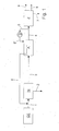
- Fig. 1 the inventive method is shown schematically, wherein a compressor in the Regeneriergas Arthur for returning the laden regeneration gas is used before the CO 2 scrubbing.
- the synthesis gas coming from the synthesis gas production GE is fed via line 1 to the CO 2 scrub W. There, most of the CO 2 - but also other unwanted substances - washed out and removed via line 2 from the process. Via line 3 , the synthesis gas passes into the adsorber station A, where it is cleaned of the remaining residues of undesirable substances, before it is passed via line 4 in the cryogenic gas separation unit Z. The residual gas fraction from Z is added via line 7 to a torch, while the CO and H 2 fractions are continued via lines 8 and 9 .
- the purified synthesis gas stream, a partial stream is removed and returned via the lines 5 and 5 'as regeneration to adsorber A , where it flows after heating in a steam or electric heater (not shown) through an adsorber to be regenerated and with the desorbed there substances (especially CO 2 and water) enriches.
- the loaded regeneration gas is returned via line 6 before the CO 2 scrub W and mixed with the synthesis crude gas stream in line 1 .
- the synthesis gas used as regeneration gas is thus circulated and remains in the process in this way.
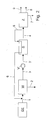
- FIG. 1 Another variant of the method according to the invention is shown schematically in FIG .
- the only difference to the variant shown in Fig. 1 lies in the arrangement of the compressor V ' in the synthesis gas stream, which is the synthesis gas flows in via line 3 and it transports it via line 3 ' to the adsorber A further.
- Fig. 3 shows schematically the case of a synthesis gas plant in which in addition to CO and H 2 also oxo gas is produced as a product.
- partial streams of the CO and H 2 fractions are branched off via lines 10 and 11 and mixed in line 12 to give oxo gas.
- the synthesis gas taken via line 5 from the synthesis gas stream and used as regeneration gas and laden with the substances desorbed in adsorber station A is passed via line 6 to line 12 where it is admixed with the oxogas product.
- the pressure gradient between the synthesis gas and the Oxogas slaughter is so high that can be dispensed with a compressor for transporting the regeneration gas.
- Fig. 4 shows schematically the case of a synthesis gas plant in which in addition to CO and H 2 and methanol synthesis gas is produced as a product.
- the synthesis gas which is produced in GE 'and is at least partially subjected to CO conversion depending on the product ratios, passes via line 1 to CO 2 scrubbing W, which is designed as a Rectisol wash and operates at about -40.degree.
- a partial stream of (treated in the wash) synthesis gas is diverted via line 13 from W and mixed with a partial flow of the H 2 fraction, which is fed via line 11 , in line 14 to methanol synthesis gas.
- the regeneration gas withdrawn via line 5 to the synthesis gas stream is returned to the CO 2 scrubber W, where it is heated against the synthesis crude gas flowing in via line 1 and passed through line 5 'to the adsorber A for the regeneration of the adsorber.
- the loaded regeneration gas flows off via line 6 and is mixed in line 14 with the methanol synthesis gas.
- the Regeneriergasstrom is interrupted via line 5 'and instead synthesis gas, which is not warmed in the Rectisolicasche, fed to the adsorber via line 15 .
- the residual gas from the cryogenic gas separation unit Z is returned via line 7 to the CO 2 scrubbing W , there compressed by a Recyclegasverêtr (not shown) in the synthesis gas and finally fed via line 13 into the methanol synthesis gas.
- FIG. 5 also schematically shows a synthesis gas plant in which, in addition to CO and H 2 , methanol synthesis gas is also produced as product.
- the purified synthesis gas is recycled via line 4 ' to CO 2 scrubbing and warmed against the flowing via line 1 synthesis gas before it is forwarded via line 4 in the cryogenic gas separation unit Z.
- Via line 5 a partial stream is diverted from the heated synthesis gas and fed to the adsorbers in the adsorber A.
- the loaded regeneration gas flows off via line 6 and is mixed in line 14 with the methanol synthesis gas.
- the Regeneriergasstrom is interrupted via line 5 and instead synthesis gas, which is not heated in the CO 2 scrubber, fed via line 16 .
- a process variant is outlined, which allows to regenerate the adsorber during the start-up operation, if no or not enough regular regeneration, which is supplied via line 7 from the cryogenic gas separation unit Z and loaded discharged via line 17 , for regeneration the adsorber is available.
- the purified synthesis gas removed via line 5 is passed through the adsorber station as a regeneration gas.
- the loaded regeneration gas is removed via line 6 and used as fuel gas or placed in the torch.
- the loaded regeneration gas can also be fed into a pressure swing adsorption (DWA) plant to recover pure hydrogen.
- DWA pressure swing adsorption
Landscapes
- Engineering & Computer Science (AREA)
- Chemical & Material Sciences (AREA)
- Organic Chemistry (AREA)
- Physics & Mathematics (AREA)
- General Engineering & Computer Science (AREA)
- Mechanical Engineering (AREA)
- Thermal Sciences (AREA)
- Analytical Chemistry (AREA)
- Oil, Petroleum & Natural Gas (AREA)
- Chemical Kinetics & Catalysis (AREA)
- Combustion & Propulsion (AREA)
- Inorganic Chemistry (AREA)
- General Chemical & Material Sciences (AREA)
- Separation Of Gases By Adsorption (AREA)
- Hydrogen, Water And Hydrids (AREA)
- Solid-Sorbent Or Filter-Aiding Compositions (AREA)
- Treatment Of Liquids With Adsorbents In General (AREA)
- Organic Low-Molecular-Weight Compounds And Preparation Thereof (AREA)
Abstract
Description
- Gegenstand der Erfindung ist ein Verfahren zur Regenerierung der Adsorber einer Adsorberstation, die zur Reinigung einer kryogenen Gaszerlegungseinheit einer Synthesegasanlage zuströmenden Synthesegases eingesetzt wird.
- Synthesegas ist ein Gasgemisch, das vorwiegend aus Wasserstoff (H2), Kohlenmonoxid (CO) und Methan (CH4) besteht, wobei seine genaue Zusammensetzung vom Herstellungsverfahren und den eingesetzten Rohstoffen abhängt.
- Als Hauptquelle für Synthesegas ist die katalytische Dampfreformierung zu nennen, bei der Erdgas, Flüssiggas oder Naphta unter Zugabe von Wasserdampf gespalten werden. Darüber hinaus kann Synthesegas auch durch die partielle Oxidation von z. B. Schweröl oder Kohle auf wirtschaftliche Weise erzeugt werden.
- Das Synthesegas selbst dient als Grundstoff für eine Vielzahl von Produkten, wozu es jedoch gereinigt und meist in seine Hauptbestandteile zerlegt werden muss. Der größte Teil des so gewonnenen CO wird zur Produktion von Ameisen- oder Essigsäure eingesetzt. Ein weiterer großer Abnehmer findet sich in der Polykarbonatindustrie, die zur Herstellung von hochreinem Phosgen CO in höchster Reinheit benötigt. Aus Synthesegas gewonnener Wasserstoff findet bei verschiedenen Hydrierprozessen Verwendung.
- Zur Trennung der Synthesegaskomponenten werden in Industrieanlagen vor allem der Kondensationsprozess und die Methanwäsche angewendet, wobei es sich in beiden Fällen um kryogene Verfahren handelt. Voraussetzung für die Anwendbarkeit dieser Prozesse ist, dass das der kryogenen Gaszerlegungseinheit zugeführte Gas frei ist von Wasser, Methanol, Kohlendioxid (CO2) und anderen Verbindungen, die bei den auftretenden niedrigen Temperaturen zur Feststoffbildung und damit zu einer Verlegung der Wärmetauscher führen würden. Das Syntheserohgas wird daher einer aus mehreren Schritten bestehenden Vorbehandlung unterzogen, während der es z. B. eine CO-Konvertierung durchläuft und in einer CO2-Wäsche vom größten Teil der unerwünschten Stoffe gereinigt wird. Die noch verbliebenen Reste werden in einer sich anschließenden Adsorberstation adsorptiv entfernt.
- Die eingesetzten Adsorberstationen bestehen aus mindestens zwei regenerierbaren Adsorbern, die jeweils mindestens ein Adsorberbett (Festbett aus einem oder mehreren geeigneten Adsorptionsmitteln) enthalten. Das vorgereinigte Syntheserohgas durchströmt das Adsorberbett und gibt dabei die in ihm enthaltenen unerwünschten Stoffe (z. B. liegt CO2 noch mit <50mol-ppm vor), an das oder die Adsorptionsmittel ab. Nach Ablauf der Adsorptionszeit erfolgt die Umschaltung von dem mit unerwünschten Stoffen beladenen Adsorber auf einen unbeladenen Adsorber der Adsorberstation. Der beladene Adsorber wird anschließend regeneriert, d. h. von den zuvor adsorbierten Stoffen gereinigt.
- Die Kapazität der eingesetzten Adsorptionsmittel ist stark temperaturabhängig. Um einen Adsorber zu regenerieren wird er daher zuerst vom Synthesegasstrom isoliert und anschließend mit heißem Regeneriergas entgegen der Strömungsrichtung des Syntheserohgases durchströmt. Die bei der erhöhten Temperatur aus dem Adsorberbett desorbierten Stoffe werden gemeinsam mit dem Regeneriergas aus dem Adsorber ausgetragen. Abhängig von seiner Zusammensetzung wird das mit den desorbierten Stoffen beladene Regeneriergas unterschiedlich behandelt.
- In der Regel wird als Regeneriergas ein Teil der H2-Fraktion (H2-Gehalt > ca. 90mol-%; unter Druck stehend) aus der kryogenen Gaszerlegungseinheit verwendet. Soll in der Anlage neben CO auch hochreiner Wasserstoff als Produkt erzeugt werden, so wird das beladene Regeneriergas abgekühlt, anfallendes Kondensat abgetrennt, mit der übrigen H2-Fraktion gemischt und dann einer Druckwechseladsorptionsanlage (DWA) zugeführt. Dort wird hochreiner Wasserstoff gewonnen und als Produkt an der Anlagengrenze abgegeben, während die übrigen Stoffe, die im Restgas mit niedrigem Druck anfallen (auch evtl. vorhandenes CO), anschließend unterfeuert werden. Nach der Regenerierung steht der Adsorber wieder für die Reinigung des Syntheserohgases zur Verfügung.
- Die Selektivität der eingesetzten Adsorptionsmittel ist zwar hoch, jedoch wird neben den unerwünschten Stoffen auch CO - wenn auch in geringerem Maß - co-adsorbiert und aus dem Synthesegas entfernt. Ist der Partialdruck des Kohlenmonoxids im Regeneriergas geringer als im Syntheserohgas, wird ein Teil des adsorbierten CO bei der Regenerierung desorbiert. Da in der nächsten Adsorptionsphase (Reinigung des Syntheserohgases) wieder CO aus dem Syntheserohgas adsorbiert wird, kann eine solchermaßen durchgeführte Adsorberregenerierung zu Schwankungen der Zusammensetzung des in die kryogene Gaszerlegungseinheit eintretenden Synthesegases und folglich auch der an der Anlagengrenze abgegebenen Produktmengen führen. Außerdem kann eine schwankende Synthesegaszusammensetzung zu einem instabilen Betrieb der kryogenen Gaszerlegungseinheit führen, was u. U. auch zu einer Verminderung der Produktreinheit führt. Da die gewöhnlich als Regeneriergas genutzte H2-Fraktion aus der kryogenen Gaszerfegungseinheit einen im Vergleich zum Synthesegas geringeren CO-Gehalt aufweist, treten bei dieser Verfahrensweise die oben beschriebenen negativen Erscheinungen auf.
- Im Moment des Umschaltens des Syntheserohgasstromes auf einen frisch regenerierten Adsorber ist dieser noch mit Regeneriergas gefüllt, das durch das Syntheserohgas verdrängt und in die kryogene Gaszerlegungseinheit transportiert wird. Besitzt das Regeneriergas eine andere Zusammensetzung als das Syntheserohgas (z. B. bei Regenerierung mit Stickstoff (N2)), kann es, zumindest kurzzeitig, zu unerwünschten Schwankungen der Produktqualität kommen.
- Die in der kryogenen Gaszerlegungseinheit anfallende Restgasfraktion (Gemisch verschiedener Gase) reicht in der Regel quantitativ nicht aus, um alleine mit ihr die Adsorber regenerieren zu können. Eine technische Lösung sieht vor die Restgasmenge durch Zumischung eines Teils der H2-Fraktion zu erhöhen. Da die Restgasfraktion nur mit geringem Druck anfällt, geht die zugemischte H2-Fraktion als Produkt verloren, und es kann lediglich ihr Heizwert genutzt werden. Wegen des geringen Druckes des Restgases ist es notwendig, vor dem Umschalten des Synthesegases auf den frisch regenerierten Adsorber diesen zunächst wieder mit Synthesegas aufzudrücken, was wiederum Schwankungen für die Produktmengen und zusätzlichen Zeitaufwand bedeutet. Ein entsprechender Druckabbau muss für den beladenen Adsorber vor Beginn der Regenerierung durchgeführt werden.
- Wenn die H2-Fraktion aus der kryogenen Gaszerlegungseinheit direkt als Produktwasserstoff abgegeben werden kann, wie dies beispielsweise bei der H2-Fraktion aus einer Methanwäsche der Fall ist, die zu ca. 99mol-% aus Wasserstoff besteht und deren CO-Gehalt unter 10mol-ppm liegt, kann diese ebenfalls nicht zur Regenerierung verwendet werden, da eine Verunreinigung des H2-Produktes mit CO nicht zulässig ist. Darüber hinaus entsteht durch die Verwendung der H2-Fraktion als Regeneriergas zusätzlicher Druckverlust, so dass eventuell für die gesamte H2-Menge ein zusätzlicher Verdichter eingesetzt werden muss, um den gewünschten H2-Produktabgabedruck zu erreichen.
- Die Verwendung von Produkt-H2 bzw. Stickstoff, welcher von jenseits der Anlagengrenze zugeführt werden muss, als Regeneriergas, ist zwar möglich, stellt jedoch einen erheblichen Kostenfaktor dar. Darüber hinaus kann der Einsatz von N2 als Regeneriergas, zumindest kurzzeitig, zu einem unerwünscht hohen Stickstoffanteil im CO-Produkt führen. Um dies zu verhindern, kann der frisch regenerierte Adsorber vor der Umschaltung mit Synthesegas gespült werden, was jedoch wiederum zu Verlusten und zu einem Einbruch der Produktmengen führt.
- Während des Anfahrbetriebs einer Synthesegasanlage steht kein oder nicht genügend Gas aus der kryogenen Gaszerlegungseinheit zur Verfügung, das als Regeneriergas genutzt werden kann. Auch in diesem Fall können Fremd-N2 oder Produkt-H2 als Regeneriergase verwendet werden, allerdings mit den oben beschriebenen wirtschaftlichen Nachteilen.
- Aufgabe der vorliegenden Erfindung ist es daher, ein Verfahren der eingangs genannten Art so zu gestalten, dass die Produktqualität und die Produktmenge nicht durch die Regenerierung der Adsorber beeinträchtigt werden und die Adsorber selbst dann ohne den Einsatz von Fremd- oder Produktgas regeneriert werden können, wenn kein oder nicht genügend Gas aus der kryogenen Gaszerlegungseinheit als Regeneriergas zur Verfügung steht.
- Diese Aufgabe wird erfindungsgemäß dadurch gelöst, dass dem gereinigten Synthesegasstrom hinter der Adsorberstation, jedoch noch vor seiner kryogenen Zerlegung, ein Teilstrom entnommen und als Regeneriergas zur Regenerierung der Adsorber zur Adsorberstation zurückgeführt wird, wodurch das Regeneriergas im wesentlichen die gleiche Zusammensetzung wie der zu reinigende Synthesegasstrom aufweist.
- Das als Regeneriergas zurückgeführte Synthesegas wird zunächst aufgeheizt und entgegen der Strömungsrichtung des zu reinigenden Syntheserohgases durch den oder die zu regenerierenden Adsorber geleitet, wo es sich mit den bei der erhöhten Temperatur desorbierten Stoffen anreichert. Anschließend werden der oder die Adsorber mit kaltem Regeneriergas wieder auf Betriebstemperatur gekühlt. Da Regeneriergas und Syntheserohgas nahezu die gleichen Zusammensetzungen aufweisen und sich die CO-Partialdrücke in beiden Gasen nicht wesentlich unterscheiden, kommt es in der folgenden Adsorptionsphase (Reinigung des Syntheserohgases) weder zu einer Co-Adsorption von Kohlenmonoxid noch zu einer Änderung der Synthesegaszusammensetzung aufgrund der auszuspülenden Regeneriergasmenge in dem oder den Adsorbern und damit auch nicht zu den oben beschriebenen Schwankungen der Produktqualität und der Produktmenge.
- Erfindungsgemäß wird das mit desorbierten Stoffen beladene Regeneriergas bis vor die CO2-Wäsche zurückgeführt und an dieser Stelle in den Syntheserohgasstrom eingespeist. Auf diese Weise geht es dem Prozess nicht verloren. In der CO2-Wäsche wir ein Großteil der bei der Adsorberregenerierung desorbierten Stoffe wieder entfernt, so dass es zu keiner Anreicherung der entsprechenden Komponenten im Syntheserohgasstrom kommt.
- Zur Rückführung des Regeneriergases wird zweckmäßigerweise mit Hilfe eines Verdichters durchgeführt. Verschiedene Ausgestaltungen des erfindungsgemäßen Verfahrens sehen vor, dass der Verdichter vor oder hinter der Adsorberstation in der Regeneriergasleitung oder vor oder hinter der CO2-Wäsche in der Synthesegasleitung angeordnet wird.
- Das erfindungsgemäße Verfahren mit Rückführung des beladenen Regeneriergases vor die CO2-Wäsche kann sowohl während des Normal- wie auch des Anfahrbetriebes einer Synthesegasanlage angewendet werden.
- Wird in der Synthesegasanlage Oxogas (Gemisch aus H2 und CO mit einem H2:CO-Verhältnis von ca. 1:1) oder Methanolsynthesegas als Produkt erzeugt, so sieht eine Variante des erfindungsgemäßen Verfahrens vor, das beladene Regeneriergas nicht vor die CO2-Wäsche zurückzuführen, sondern in das Oxogas- bzw. Methanolsynthesegasprodukt einzuspeisen. Reicht der Unterschied zwischen dem Druck an der Entnahmestelle des als Regeneriergas genutzten Synthesegases und dem Druck des entsprechenden Produktes aus, um die Druckverluste in der Adsorberstation und den Rohrleitungen zu kompensieren, kann auf den Einbau eines Regeneriergasverdichters verzichtet werden.
- Zur Reinigung von Syntheserohgas das aus einer partiellen Oxidation von Kohle oder Öl stammt, wird vorzugsweise eine bei tiefen Temperaturen (ca. -40°C) arbeitende Rectisolwäsche eingesetzt. Wird aus dem Syntheserohgas neben CO (und H2) auch Methanolsynthesegas erzeugt, so kann, abhängig von den Produktverhältnissen, vorher zumindest ein Teil des Syntheserohgases eine CO-Konvertierung durchlaufen. Die auf die Rectisolwäsche folgende Adsorberstation wird bevorzugt bei kalter Temperatur betrieben (erhöhte Kapazität der eingesetzten Adsorptionsmittel), um die Größe der Adsorber zu minimieren. Eine Ausgestaltung des erfindungsgemäßen Verfahrens sieht vor, das Synthesegas nach dem Austritt aus der Adsorberstation zur Kälterückgewinnung in die Rectisolwäsche zurückzuführen und dort vorzugsweise gegen das in die Rectisolwäsche einströmende Syntheserohgas anzuwärmen, bevor es in die kryogene Gaszerlegungseinheit weiter geleitet wird. Dies ist vor allem dann sinnvoll, wenn der in der Rectisolwäsche eingesparte Energiebedarf (Fremdkälte, Verdichterleistung) gegenüber dem Aufwand in der kryogenen Gaszerlegungseinheit bei erhöhter Eintrittstemperatur überwiegt. Für eine Anwärmung des gereinigten Synthesegases in der Rectisolwäsche spricht auch, dass bei erhöhter Eintrittstemperatur die aus der kryogenen Gaszerlegungseinheit stammenden Produkte nicht separat, extern (z. B. in gewickelten Wärmetauschern in der Rectisolwäsche) angewärmt werden müssen, was einen erhöhten Druckverlust verursacht, sondern direkt an den Kunden abgegeben bzw., wie im Falle des CO Produktes, direkt der Produktverdichtung zugeführt werden können. Zur Adsorberregenerierung wird ein Teil des angewärmten Synthesegases abgezweigt und mit Hilfe eines Dampf- oder Elektroerhitzers die restliche Temperaturerhöhung durchgeführt. Um die Adsorber nach der Regenerierung wieder auf Betriebstemperatur abzukühlen, wird erfindungsgemäß ein Teilstrom des kalten Synthesegases ohne Anwärmung in der Rectisolwäsche zur Adsorberstation geführt.
- Ist eine erhöhte Eintrittstemperatur in die kryogenen Gaszerlegungseinheit nicht akzeptabel (z. B. weil der Prozess keinen Kälteüberschuss besitzt, keine Fremdkälte verfügbar ist oder weil dadurch eine Expansionsturbine notwendig werden würde), wird das gereinigte Synthesegas nach der Adsorberstation direkt der kryogenen Gaszerlegungseinheit zugeführt. Bei dieser Schaltung werden die kalten Zerlegungsprodukte aus der kryogenen Gaszerlegungseinheit vor ihrer Weiterleitung in der Rectisolwäsche bis auf Umgebungstemperatur angewärmt. Eine weitere Ausgestaltung des erfindungsgemäßen Verfahrens sieht vor, den für die Adsorberregenerierung bestimmten Teilstrom des Synthesegases zur Rectisolwäsche zurückzuführen und dort vorzugsweise gegen das in die Rectisolwäsche einströmende Syntheserohgas anzuwärmen, bevor er in die Adsorberstation geleitet und mit Hilfe eines Dampf- oder Elektroerhitzers auf die für die Regenerierung erforderliche Temperatur gebracht wird. Um die Adsorber nach ihrer Regenerierung wieder abzukühlen, wird erfindungsgemäß der Teilstrom des kalten Synthesegases ohne Anwärmung in der Rectisolwäsche zur Adsorberstation geführt.
- Im Falle von Synthesegasanlagen, die u. a. auch Methanolsynthesegas produzieren, sieht eine weitere Ausgestaltung des erfindungsgemäßen Verfahrens vor, das Restgas aus der kryogenen Gaszerlegungseinheit wirtschaftlich zu nutzen, indem es über den Recyclegasverdichter der Rectisolwäsche in das Syntheserohgas zurückgeführt wird. Handelt es sich um eine zweisträngige Rectisolwäsche (2-Absorber-Konzept) so wird der Recyclestrom vorzugsweise in den Syntheserohgasstrom aus der CO-Konvertierung eingespeist und damit nach der Wäsche direkt dem Methanolsynthesegas zugeführt.
- In Synthesegasanlagen, die regulär Regeneriergas aus der kryogenen Gaszerlegungseinheit nutzen, wird das erfindungsgemäße Verfahren zweckmäßigerweise zumindest während des Anfahrbetriebes, wenn aus der kryogenen Gaszerlegungseinheit noch kein oder nicht genug Gas bezogen werden kann, eingesetzt. In der Regel wird in diesem Fall das Synthesegas nach der Adsorberregenerierung nicht vor die CO2-Wäsche zurückgeführt, sondern als Brenngas verwendet oder in die Fackel gegeben. Auf einen Regeneriergasverdichter kann verzichtet werden, da ausreichend Druckgefälle zur Verfügung steht. Altemativ dazu kann das Regeneriergas auch in eine Druckwechseladsorptionsanlage (DWA) geführt werden, um Reinwasserstoff zu gewinnen.
- Im Folgenden soll das erfindungsgemäße Verfahren anhand der in den Figuren 1 bis 6 schematisch dargestellten Ausführungsbeispiele näher erläutert werden. In den Figuren bezeichnen gleiche Symbole gleiche Anlagenteile bzw. Leitungen, in denen gleiche Stoffe transportiert werden.
- In Fig. 1 ist das erfindungsgemäße Verfahren schematisch abgebildet, wobei ein Verdichter in der Regeneriergasleitung zur Rückführung des beladenen Regeneriergases vor die CO2-Wäsche eingesetzt wird.
- Das aus der Synthesegaserzeugung GE kommende Syntheserohgas wird über Leitung 1 der CO2-Wäsche W zugeführt. Dort wird der größte Teil des CO2 - aber auch anderer unerwünschter Stoffe - ausgewaschen und über Leitung 2 aus dem Prozess entfernt. Über Leitung 3 gelangt das Syntheserohgas in die Adsorberstation A, wo es von den noch verbliebenen Resten an unerwünschten Stoffen gereinigt wird, bevor es über Leitung 4 in die kryogene Gaszerlegungseinheit Z geleitet wird. Die Restgasfraktion aus Z wird über Leitung 7 auf ein Fackel gegeben, während die CO- und die H2-Fraktion über die Leitungen 8 und 9 weitergeführt werden.
- Dem gereinigten Synthesegasstrom wird ein Teilstrom entnommen und über die Leitungen 5 und 5' als Regeneriergas zur Adsorberstation A zurückgeführt, wo es nach Aufheizung in einem Dampf- oder Elektroerhitzer (nicht eingezeichnet) durch einen zu regenerierenden Adsorber strömt und sich mit den dort desorbierten Stoffen (vor allem CO2 und Wasser) anreichert. Anschließend wird das beladene Regeneriergas über Leitung 6 vor die CO2-Wäsche W zurückgeleitet und mit dem Syntheserohgasstrom in Leitung 1 gemischt. Das als Regeneriergas genutzte Synthesegas wird also in einem Kreislauf geführt und verbleibt auf diese Weise im Prozess.
- An der Entnahmestelle des Regeneriergases hinter der Adsorberstation A herrscht ein geringerer Druck als vor der CO2-Wäsche W. Um das als Regeneriergas verwendete Synthesegas bis vor die CO2-Wäsche W zurückführen zu können, muss dieser Druckunterschied sowie der Druckverlust über den Regeneriergasweg kompensiert werden. Zu diesem Zweck ist ein Verdichter V in die Regeneriergasleitung vor der Adsorberstation A eingebaut.
- Eine andere Variante des erfindungsgemäßen Verfahrens ist in Fig. 2 schematisch dargestellt. Der einzige Unterschied zu der in Fig. 1 dargestellten Variante liegt in der Anordnung des Verdichters V' im Syntheserohgasstrom, dem das Syntheserohgas über Leitung 3 zuströmt und der es über Leitung 3' zur Adsorberstation A weiter transportiert.
- Die Fig. 3 zeigt schematisch den Fall einer Synthesegasanlage, in der neben CO und H2 auch Oxogas als Produkt erzeugt wird. Zu diesem Zweck werden Teilströme der CO- und der H2-Fraktion über die Leitungen 10 und 11 abgezweigt und in Leitung 12 zu Oxogas gemischt. Das über Leitung 5 aus dem Synthesegasstrom entnommene, als Regeneriergas verwendete und mit den in der Adsorberstation A desorbierten Stoffen beladene Synthesegas wird über Leitung 6 zur Leitung 12 geführt und dort dem Oxogasprodukt beigemischt. Das Druckgefälle zwischen dem Synthesegas und dem Oxogasprodukt ist so hoch, dass auf einen Verdichter zum Transport des Regeneriergases verzichtet werden kann.
- Die Fig. 4 zeigt schematisch den Fall einer Synthesegasanlage, in der neben CO und H2 auch Methanolsynthesegas als Produkt erzeugt wird. Das Syntheserohgas, das in GE' erzeugt und abhängig von den Produktverhältnissen zumindest teilweise einer CO-Konvertierung unterzogen wird, gelangt über Leitung 1 zur CO2-Wäsche W, die als Rectisolwäsche ausgeführt ist und bei ca. -40°C arbeitet. Ein Teilstrom des (in der Wäsche behandelten) Syntheserohgases wird über Leitung 13 aus W abgezweigt und mit einem Teilstrom der H2-Fraktion, die über Leitung 11 zugeleitet wird, in Leitung 14 zu Methanolsynthesegas gemischt. Das über Leitung 5 dem Synthesegasstrom entnommene Regeneriergas wird zur CO2-Wäsche W, zurückgeführt, dort gegen das über Leitung 1 einströmende Syntheserohgas angewärmt und über Leitung 5' zur Regenerierung der Adsorber in die Adsorberstation A geleitet. Das beladene Regeneriergas strömt über Leitung 6 ab und wird in Leitung 14 dem Methanolsynthesegas beigemischt. Um einen Adsorber nach seiner Regenerierung wieder abzukühlen, wird der Regeneriergasstrom über Leitung 5' unterbrochen und stattdessen Synthesegas, das nicht in der Rectisolwäsche angewärmt wird, dem Adsorber über Leitung 15 zugeführt. Das Restgas aus der kryogenen Gaszerlegungseinheit Z wird über Leitung 7 zur CO2-Wäsche W zurückgeführt, dort durch einen Recyclegasverdichter (nicht gezeigt) in das Syntheserohgas verdichtet und schließlich über Leitung 13 in das Methanolsynthesegas geführt.
- Die Fig. 5 zeigt schematisch ebenfalls eine Synthesegasanlage, in der neben CO und H2 auch Methanolsynthesegas als Produkt erzeugt wird. Das gereinigte Synthesegas wird über Leitung 4' zur CO2-Wäsche zurückgeführt und gegen das über Leitung 1 einströmende Syntheserohgas angewärmt, bevor es über Leitung 4 in die kryogene Gaszerlegungseinheit Z weitergeleitet wird. Über Leitung 5 wird ein Teilstrom aus dem angewärmten Synthesegas abgezweigt und zu den Adsorbern in die Adsorberstation A geführt. Das beladene Regeneriergas strömt über Leitung 6 ab und wird in Leitung 14 dem Methanolsynthesegas beigemischt. Um die Adsorber nach ihrer Regenerierung wieder abzukühlen, wird der Regeneriergasstrom über Leitung 5 unterbrochen und stattdessen Synthesegas, das nicht in der CO2-Wäsche angewärmt wird, über Leitung 16 zugeführt.
- In Fig. 6 ist eine Verfahrensvariante skizziert, die es erlaubt, die Adsorber während des Anfahrbetriebes zu regenerieren, wenn noch kein oder nicht genügend reguläres Regeneriergas, das über Leitung 7 aus der kryogenen Gaszerlegungseinheit Z zugeführt und beladen über Leitung 17 abgeführt wird, zur Regenerierung der Adsorber zur Verfügung steht. Das über Leitung 5 entnommene gereinigte Synthesegas wird als Regeneriergas durch die Adsorberstation geleitet. Das beladene Regeneriergas wird über Leitung 6 abgeführt und als Brenngas verwendet oder in die Fackel gegeben. Altemativ dazu kann das beladene Regeneriergas auch in eine Druckwechseladsorptionsanlage (DWA) geführt werden, um Reinwasserstoff zu gewinnen.
Claims (10)
- Verfahren zur Regenerierung der Adsorber einer Adorberstation, die zur Reinigung des einer kryogenen Gaszerlegungseinheit einer Synthesegasanlage zuströmenden Synthesegases eingesetzt wird, dadurch gekennzeichnet, dass dem gereinigten Synthesegasstrom hinter der Adsorberstation, jedoch noch vor seiner kryogenen Zerlegung, ein Teilstrom entnommen und als Regeneriergas zur Regenerierung der Adsorber zur Adsorberstation zurückgeführt wird, wodurch das Regeneriergas im wesentlichen die gleiche Zusammensetzung wie der zu reinigende Synthesegasstrom aufweist.
- Verfahren nach Anspruch 1, dadurch gekennzeichnet, dass das als Regeneriergas verwendete Synthesegas nach dem Durchtritt durch den oder die zu regenerierenden Adsorber vor die CO2-Wäsche in den Syntheserohgasstrom zurückgeführt wird.
- Verfahren nach einem der Ansprüche 1 oder 2, dadurch gekennzeichnet, dass das Regeneriergas durch einen vor oder hinter den Adsorbern der Adsorberstation in den Weg des Regeneriergases eingebauten Verdichter zurück in den Synthesegasstrom geführt wird.
- Verfahren nach einem der Ansprüche 1 oder 2, dadurch gekennzeichnet, dass das für die Rückführung des Regeneriergases notwendige Druckgefälle durch einen vor oder hinter der CO2-Wäsche in den Weg des Syntheserohgases eingebauten Verdichter erzeugt wird.
- Verfahren nach Anspruch 1, dadurch gekennzeichnet, dass in Anlagen zur Gewinnung eines Oxogasproduktes oder von Methanolsynthesegas das als Regeneriergas verwendete Synthesegas nach dem Durchtritt durch den oder die zu regenerierenden Adsorber dem Oxogasprodukt bzw. dem Methanolsynthesegas beigemischt wird.
- Verfahren nach Anspruch 1, dadurch gekennzeichnet, dass in Anlagen, in denen unter anderem auch Methanolsynthesegas erzeugt wird, das Synthesegas nach der Reinigung in der Adsorberstation zur CO2-Wäsche zurückgeführt, dort vorzugsweise gegen das abzukühlende Syntheserohgas angewärmt und anschließend zur kryogenen Gaszerlegungseinheit weitergeleitet wird, wobei dem angewärmten Synthesegasstrom nach der CO2-Wäsche, jedoch noch vor seiner kryogenen Zerlegung, ein Teilstrom entnommen und als Regeneriergas zur Regenerierung der Adsorber der Adsorberstation verwendet wird und das beladene Regeneriergas in das Methanolsynthesegas eingespeist wird.
- Verfahren nach Anspruch 6, dadurch gekennzeichnet, dass dem Synthesegasstrom nach der Adsorberstation, jedoch noch vor der CO2-Wäsche ein Teilstrom entnommen und zur Kühlung der Adsorber der Adsorberstation nach der Regenerierung verwendet wird und anschließend in das Methanolsynthesegas eingespeist wird.
- Verfahren nach Anspruch 1, dadurch gekennzeichnet, dass in Anlagen, in denen unter anderem auch Methanolsynthesegas erzeugt wird, das Regeneriergas zur CO2-Wäsche zurückgeführt und dort vorzugsweise gegen das abzukühlende Syntheserohgas angewärmt, zur Regenerierung der Adsorber der Adsorberstation verwendet und anschließend in das Methanolsynthesegas eingespeist wird.
- Verfahren nach Anspruch 8, dadurch gekennzeichnet, dass zur Kühlung der Adsorber der Adsorberstation nach der Regenerierung kaltes Synthesegas verwendet wird, dass nicht in der CO2-Wäsche angewärmt wird und anschließend in das Methanolsynthesegas eingespeist wird.
- Verfahren nach Anspruch 1, dadurch gekennzeichnet, dass in Synthesegasanlagen, welche regulär Gas aus der kryogenen Gaszerlegungseinheit als Regeneriergas nutzen ein Teilstrom des Synthesegases als Regeneriergas verwendet wird, solange während des Anfahrbetriebes kein oder nicht genügend reguläres Regeneriergas zur Verfügung steht, wobei das Synthesegas nach dem Durchtritt durch den oder die zu regenerierenden Adsorber als Brenngas verwendet oder in die Fackel gegeben oder zur Gewinnung von Reinwasserstoff in eine Druckwechseladsorptionsanlage (DWA) geführt wird.
Applications Claiming Priority (1)
| Application Number | Priority Date | Filing Date | Title |
|---|---|---|---|
| DE102005009393A DE102005009393A1 (de) | 2005-03-01 | 2005-03-01 | Verfahren zur Adsorberregenerierung |
Publications (2)
| Publication Number | Publication Date |
|---|---|
| EP1698607A1 true EP1698607A1 (de) | 2006-09-06 |
| EP1698607B1 EP1698607B1 (de) | 2008-10-22 |
Family
ID=36405914
Family Applications (1)
| Application Number | Title | Priority Date | Filing Date |
|---|---|---|---|
| EP06004017A Expired - Lifetime EP1698607B1 (de) | 2005-03-01 | 2006-02-28 | Verfahren zur Adsorberregenerierung |
Country Status (7)
| Country | Link |
|---|---|
| US (1) | US7517390B2 (de) |
| EP (1) | EP1698607B1 (de) |
| CN (1) | CN1833752A (de) |
| AT (1) | ATE411973T1 (de) |
| DE (2) | DE102005009393A1 (de) |
| ES (1) | ES2315951T3 (de) |
| TW (1) | TW200640560A (de) |
Cited By (1)
| Publication number | Priority date | Publication date | Assignee | Title |
|---|---|---|---|---|
| EP2709745B1 (de) * | 2011-05-16 | 2020-04-01 | L'Air Liquide Société Anonyme pour l'Etude et l'Exploitation des Procédés Georges Claude | Verfahren zur reinigung durch adsorption mit regeneration anhand eines gases mit einer unerwünschten komponente im gereinigten gas |
Families Citing this family (11)
| Publication number | Priority date | Publication date | Assignee | Title |
|---|---|---|---|---|
| FR2884305A1 (fr) * | 2005-04-08 | 2006-10-13 | Air Liquide | Procede de recuperation et liquefaction du co2 contenu dans un gaz pauvre en co2 |
| FR2909898B1 (fr) * | 2006-12-18 | 2009-08-21 | Air Liquide | Purification d'un melange h2/co avec controle de la temperature de peau du rechauffeur |
| US8591631B2 (en) * | 2007-07-31 | 2013-11-26 | General Electric Company | Method and apparatus to produce synthetic gas |
| EP2311544A1 (de) * | 2009-10-05 | 2011-04-20 | L'Air Liquide Société Anonyme pour l'Etude et l'Exploitation des Procédés Georges Claude | Verfahren und Vorrichtung zur Aufbereitung eines Synthesegases |
| CN102091502A (zh) * | 2009-12-10 | 2011-06-15 | 琳德股份公司 | 气体预纯化方法 |
| CN102091498B (zh) * | 2009-12-14 | 2015-07-01 | 琳德股份公司 | 对苯二甲酸生产的尾气的处理方法 |
| US8491704B2 (en) | 2011-01-11 | 2013-07-23 | Praxair Technology, Inc. | Six bed pressure swing adsorption process operating in normal and turndown modes |
| US8496733B2 (en) | 2011-01-11 | 2013-07-30 | Praxair Technology, Inc. | Large scale pressure swing adsorption systems having process cycles operating in normal and turndown modes |
| US8551217B2 (en) | 2011-01-11 | 2013-10-08 | Praxair Technology, Inc. | Six bed pressure swing adsorption process operating in normal and turndown modes |
| US8435328B2 (en) | 2011-01-11 | 2013-05-07 | Praxair Technology, Inc. | Ten bed pressure swing adsorption process operating in normal and turndown modes |
| DE102011112655A1 (de) * | 2011-09-06 | 2013-03-07 | Linde Ag | Behandlung einer kohlendioxidreichen Fraktion einer Anlage zur Produktion von Wasserstoff und Kohlenmonoxid |
Citations (5)
| Publication number | Priority date | Publication date | Assignee | Title |
|---|---|---|---|---|
| US4469665A (en) * | 1979-12-19 | 1984-09-04 | Imperial Chemical Industries Plc | Production of ammonia from purified ammonia synthesis gas |
| US4546111A (en) * | 1983-04-22 | 1985-10-08 | Foster Wheeler Energy Corporation | Process for the production of oxygenated organic compounds such as methanol |
| EP0289877A1 (de) * | 1987-04-28 | 1988-11-09 | Air Products And Chemicals, Inc. | Gastrennverfahren |
| DE3914361A1 (de) * | 1989-04-29 | 1990-10-31 | Linde Ag | Verfahren zur erzeugung von ammoniaksynthesegas |
| US20030113257A1 (en) * | 2001-12-14 | 2003-06-19 | Hisashi Kobayashi | Method for producing hydrogen |
Family Cites Families (6)
| Publication number | Priority date | Publication date | Assignee | Title |
|---|---|---|---|---|
| US4752311A (en) * | 1986-02-24 | 1988-06-21 | The Boc Group, Inc. | Argon recovery from ammonia plant purge gas utilizing a combination of cryogenic and non-cryogenic separating means |
| US4846851A (en) * | 1987-10-27 | 1989-07-11 | Air Products And Chemicals, Inc. | Purification of ammonia syngas |
| US5152975A (en) * | 1991-03-15 | 1992-10-06 | Texaco Inc. | Process for producing high purity hydrogen |
| US5897686A (en) * | 1997-10-22 | 1999-04-27 | Air Products And Chemicals, Inc. | Synthesis gas drying and CO2 removal |
| FR2832141B1 (fr) * | 2001-11-14 | 2004-10-01 | Ceca Sa | Procede de purification de gaz de synthese |
| FR2838424B1 (fr) * | 2002-04-15 | 2004-05-28 | Air Liquide | Procede et installation de separation d'un melange d'hydrogene et de monoxyde de carbone |
-
2005
- 2005-03-01 DE DE102005009393A patent/DE102005009393A1/de not_active Withdrawn
-
2006
- 2006-02-24 TW TW095106298A patent/TW200640560A/zh unknown
- 2006-02-28 AT AT06004017T patent/ATE411973T1/de not_active IP Right Cessation
- 2006-02-28 US US11/363,042 patent/US7517390B2/en not_active Expired - Fee Related
- 2006-02-28 DE DE502006001860T patent/DE502006001860D1/de not_active Expired - Lifetime
- 2006-02-28 ES ES06004017T patent/ES2315951T3/es not_active Expired - Lifetime
- 2006-02-28 EP EP06004017A patent/EP1698607B1/de not_active Expired - Lifetime
- 2006-03-01 CN CNA2006100198291A patent/CN1833752A/zh active Pending
Patent Citations (5)
| Publication number | Priority date | Publication date | Assignee | Title |
|---|---|---|---|---|
| US4469665A (en) * | 1979-12-19 | 1984-09-04 | Imperial Chemical Industries Plc | Production of ammonia from purified ammonia synthesis gas |
| US4546111A (en) * | 1983-04-22 | 1985-10-08 | Foster Wheeler Energy Corporation | Process for the production of oxygenated organic compounds such as methanol |
| EP0289877A1 (de) * | 1987-04-28 | 1988-11-09 | Air Products And Chemicals, Inc. | Gastrennverfahren |
| DE3914361A1 (de) * | 1989-04-29 | 1990-10-31 | Linde Ag | Verfahren zur erzeugung von ammoniaksynthesegas |
| US20030113257A1 (en) * | 2001-12-14 | 2003-06-19 | Hisashi Kobayashi | Method for producing hydrogen |
Cited By (1)
| Publication number | Priority date | Publication date | Assignee | Title |
|---|---|---|---|---|
| EP2709745B1 (de) * | 2011-05-16 | 2020-04-01 | L'Air Liquide Société Anonyme pour l'Etude et l'Exploitation des Procédés Georges Claude | Verfahren zur reinigung durch adsorption mit regeneration anhand eines gases mit einer unerwünschten komponente im gereinigten gas |
Also Published As
| Publication number | Publication date |
|---|---|
| DE102005009393A1 (de) | 2006-09-14 |
| US20060199723A1 (en) | 2006-09-07 |
| EP1698607B1 (de) | 2008-10-22 |
| ES2315951T3 (es) | 2009-04-01 |
| DE502006001860D1 (de) | 2008-12-04 |
| ATE411973T1 (de) | 2008-11-15 |
| US7517390B2 (en) | 2009-04-14 |
| CN1833752A (zh) | 2006-09-20 |
| TW200640560A (en) | 2006-12-01 |
Similar Documents
| Publication | Publication Date | Title |
|---|---|---|
| DE69014675T2 (de) | Absorptionsverfahren zur Rückgewinnung von zwei hochreinen Gasprodukten aus zusammengesetzten Gasgemischen. | |
| DE3851822T2 (de) | Trennung von Wasserstoff enthaltenden Gasmischungen. | |
| DE2629450A1 (de) | Selektives adsorptionsverfahren | |
| EP1698607B1 (de) | Verfahren zur Adsorberregenerierung | |
| DE2548700A1 (de) | Verfahren und vorrichtung zur gewinnung von wasserstoff und kohlendioxid | |
| DE1544080A1 (de) | Verfahren zur Reinigung von Synthesegasen | |
| EP3666364B1 (de) | Verfahren und vorrichtung zur regenerierung eines beladenen waschmittels aus einer gaswäsche | |
| DE102005051952B3 (de) | Verfahren zur Herstellung von Methan und flüssigem Kohlendioxid aus Raffinerie- und/oder Biogas | |
| EP1729077B1 (de) | Verfahren und Vorrichtung zur Gewinnung von Produkten aus Synthesegas | |
| EP0146082A2 (de) | Verfahren zur adsorptiven Abtrennung von Wasserdampf und Kohlendioxid aus einem Gasstrom | |
| DE102010022501A1 (de) | Verfahren und Vorrichtung zur Wäsche von Synthesegas | |
| EP1724542B1 (de) | Verfahren und Vorrichtung zur Gewinnung von Produkten aus Synthesegase | |
| EP3102308B1 (de) | Verfahren zum erzeugen und reinigen eines synthesegases | |
| DE2624346C2 (de) | ||
| DE2906057A1 (de) | Druckwechseladsorptionsverfahren zur zerlegung oder reinigung von gasgemischen | |
| EP1519781B1 (de) | Anlageneinheit zur desorption von kohlendioxid aus methanol | |
| DE102012023937A1 (de) | Verfahren zur Entfernung von Sauergasen aus einem Restgas einer Alkoholsynthese | |
| EP3401280B1 (de) | Verfahren zur herstellung von ammoniak | |
| EP3746210A1 (de) | Verfahren zur trennung eines gasgemischstroms mittels temperaturwechseladsorption und temperaturwechseladsorptionsanlage | |
| DE102007055296A1 (de) | Verfahren und Vorrichtung zur Waschmittelregenerierung | |
| DE3322473A1 (de) | Verfahren und vorrichtung zur vermeidung einer anreicherung unerwuenschter komponenten in einem fluessigen medium | |
| DE102007062210A1 (de) | Verfahren und Vorrichtung zur Rückführung verunreinigter Gasströme in Synthesegasanlagen | |
| EP3333123B1 (de) | Verfahren und anlage zur erzeugung von synthesegas | |
| WO2014043730A2 (de) | Vorrichtung und verfahren zur auftrennung eines gasgemisches | |
| DE3032799C2 (de) | Verfahren und Vorrichtung zur Erzeugung von Ammoniaksynthesegasgemischen |
Legal Events
| Date | Code | Title | Description |
|---|---|---|---|
| PUAI | Public reference made under article 153(3) epc to a published international application that has entered the european phase |
Free format text: ORIGINAL CODE: 0009012 |
|
| AK | Designated contracting states |
Kind code of ref document: A1 Designated state(s): AT BE BG CH CY CZ DE DK EE ES FI FR GB GR HU IE IS IT LI LT LU LV MC NL PL PT RO SE SI SK TR |
|
| AX | Request for extension of the european patent |
Extension state: AL BA HR MK YU |
|
| 17P | Request for examination filed |
Effective date: 20070130 |
|
| 17Q | First examination report despatched |
Effective date: 20070313 |
|
| AKX | Designation fees paid |
Designated state(s): AT BE BG CH CY CZ DE DK EE ES FI FR GB GR HU IE IS IT LI LT LU LV MC NL PL PT RO SE SI SK TR |
|
| RAP1 | Party data changed (applicant data changed or rights of an application transferred) |
Owner name: LINDE AKTIENGESELLSCHAFT |
|
| GRAP | Despatch of communication of intention to grant a patent |
Free format text: ORIGINAL CODE: EPIDOSNIGR1 |
|
| GRAS | Grant fee paid |
Free format text: ORIGINAL CODE: EPIDOSNIGR3 |
|
| GRAA | (expected) grant |
Free format text: ORIGINAL CODE: 0009210 |
|
| AK | Designated contracting states |
Kind code of ref document: B1 Designated state(s): AT BE BG CH CY CZ DE DK EE ES FI FR GB GR HU IE IS IT LI LT LU LV MC NL PL PT RO SE SI SK TR |
|
| REG | Reference to a national code |
Ref country code: GB Ref legal event code: FG4D Free format text: NOT ENGLISH |
|
| REG | Reference to a national code |
Ref country code: CH Ref legal event code: EP |
|
| REG | Reference to a national code |
Ref country code: IE Ref legal event code: FG4D Free format text: LANGUAGE OF EP DOCUMENT: GERMAN |
|
| REF | Corresponds to: |
Ref document number: 502006001860 Country of ref document: DE Date of ref document: 20081204 Kind code of ref document: P |
|
| NLV1 | Nl: lapsed or annulled due to failure to fulfill the requirements of art. 29p and 29m of the patents act | ||
| REG | Reference to a national code |
Ref country code: ES Ref legal event code: FG2A Ref document number: 2315951 Country of ref document: ES Kind code of ref document: T3 |
|
| PG25 | Lapsed in a contracting state [announced via postgrant information from national office to epo] |
Ref country code: LT Free format text: LAPSE BECAUSE OF FAILURE TO SUBMIT A TRANSLATION OF THE DESCRIPTION OR TO PAY THE FEE WITHIN THE PRESCRIBED TIME-LIMIT Effective date: 20081022 Ref country code: BG Free format text: LAPSE BECAUSE OF FAILURE TO SUBMIT A TRANSLATION OF THE DESCRIPTION OR TO PAY THE FEE WITHIN THE PRESCRIBED TIME-LIMIT Effective date: 20090122 |
|
| REG | Reference to a national code |
Ref country code: HU Ref legal event code: AG4A Ref document number: E004771 Country of ref document: HU |
|
| PG25 | Lapsed in a contracting state [announced via postgrant information from national office to epo] |
Ref country code: NL Free format text: LAPSE BECAUSE OF FAILURE TO SUBMIT A TRANSLATION OF THE DESCRIPTION OR TO PAY THE FEE WITHIN THE PRESCRIBED TIME-LIMIT Effective date: 20081022 Ref country code: SI Free format text: LAPSE BECAUSE OF FAILURE TO SUBMIT A TRANSLATION OF THE DESCRIPTION OR TO PAY THE FEE WITHIN THE PRESCRIBED TIME-LIMIT Effective date: 20081022 Ref country code: LV Free format text: LAPSE BECAUSE OF FAILURE TO SUBMIT A TRANSLATION OF THE DESCRIPTION OR TO PAY THE FEE WITHIN THE PRESCRIBED TIME-LIMIT Effective date: 20081022 Ref country code: FI Free format text: LAPSE BECAUSE OF FAILURE TO SUBMIT A TRANSLATION OF THE DESCRIPTION OR TO PAY THE FEE WITHIN THE PRESCRIBED TIME-LIMIT Effective date: 20081022 Ref country code: IS Free format text: LAPSE BECAUSE OF FAILURE TO SUBMIT A TRANSLATION OF THE DESCRIPTION OR TO PAY THE FEE WITHIN THE PRESCRIBED TIME-LIMIT Effective date: 20090222 Ref country code: PL Free format text: LAPSE BECAUSE OF FAILURE TO SUBMIT A TRANSLATION OF THE DESCRIPTION OR TO PAY THE FEE WITHIN THE PRESCRIBED TIME-LIMIT Effective date: 20081022 Ref country code: PT Free format text: LAPSE BECAUSE OF FAILURE TO SUBMIT A TRANSLATION OF THE DESCRIPTION OR TO PAY THE FEE WITHIN THE PRESCRIBED TIME-LIMIT Effective date: 20090323 |
|
| REG | Reference to a national code |
Ref country code: IE Ref legal event code: FD4D |
|
| PG25 | Lapsed in a contracting state [announced via postgrant information from national office to epo] |
Ref country code: DK Free format text: LAPSE BECAUSE OF FAILURE TO SUBMIT A TRANSLATION OF THE DESCRIPTION OR TO PAY THE FEE WITHIN THE PRESCRIBED TIME-LIMIT Effective date: 20081022 Ref country code: IE Free format text: LAPSE BECAUSE OF FAILURE TO SUBMIT A TRANSLATION OF THE DESCRIPTION OR TO PAY THE FEE WITHIN THE PRESCRIBED TIME-LIMIT Effective date: 20081022 Ref country code: RO Free format text: LAPSE BECAUSE OF FAILURE TO SUBMIT A TRANSLATION OF THE DESCRIPTION OR TO PAY THE FEE WITHIN THE PRESCRIBED TIME-LIMIT Effective date: 20081022 Ref country code: EE Free format text: LAPSE BECAUSE OF FAILURE TO SUBMIT A TRANSLATION OF THE DESCRIPTION OR TO PAY THE FEE WITHIN THE PRESCRIBED TIME-LIMIT Effective date: 20081022 |
|
| RAP2 | Party data changed (patent owner data changed or rights of a patent transferred) |
Owner name: LINDE AG |
|
| PLBE | No opposition filed within time limit |
Free format text: ORIGINAL CODE: 0009261 |
|
| STAA | Information on the status of an ep patent application or granted ep patent |
Free format text: STATUS: NO OPPOSITION FILED WITHIN TIME LIMIT |
|
| BERE | Be: lapsed |
Owner name: LINDE A.G. Effective date: 20090228 |
|
| PG25 | Lapsed in a contracting state [announced via postgrant information from national office to epo] |
Ref country code: CZ Free format text: LAPSE BECAUSE OF FAILURE TO SUBMIT A TRANSLATION OF THE DESCRIPTION OR TO PAY THE FEE WITHIN THE PRESCRIBED TIME-LIMIT Effective date: 20081022 Ref country code: SE Free format text: LAPSE BECAUSE OF FAILURE TO SUBMIT A TRANSLATION OF THE DESCRIPTION OR TO PAY THE FEE WITHIN THE PRESCRIBED TIME-LIMIT Effective date: 20090122 |
|
| 26N | No opposition filed |
Effective date: 20090723 |
|
| PG25 | Lapsed in a contracting state [announced via postgrant information from national office to epo] |
Ref country code: SK Free format text: LAPSE BECAUSE OF FAILURE TO SUBMIT A TRANSLATION OF THE DESCRIPTION OR TO PAY THE FEE WITHIN THE PRESCRIBED TIME-LIMIT Effective date: 20081022 Ref country code: MC Free format text: LAPSE BECAUSE OF NON-PAYMENT OF DUE FEES Effective date: 20090228 |
|
| PG25 | Lapsed in a contracting state [announced via postgrant information from national office to epo] |
Ref country code: BE Free format text: LAPSE BECAUSE OF NON-PAYMENT OF DUE FEES Effective date: 20090228 |
|
| PGFP | Annual fee paid to national office [announced via postgrant information from national office to epo] |
Ref country code: ES Payment date: 20100312 Year of fee payment: 5 Ref country code: HU Payment date: 20100216 Year of fee payment: 5 |
|
| PGFP | Annual fee paid to national office [announced via postgrant information from national office to epo] |
Ref country code: FR Payment date: 20100223 Year of fee payment: 5 Ref country code: IT Payment date: 20100220 Year of fee payment: 5 |
|
| PG25 | Lapsed in a contracting state [announced via postgrant information from national office to epo] |
Ref country code: AT Free format text: LAPSE BECAUSE OF NON-PAYMENT OF DUE FEES Effective date: 20090228 |
|
| PGFP | Annual fee paid to national office [announced via postgrant information from national office to epo] |
Ref country code: DE Payment date: 20100312 Year of fee payment: 5 Ref country code: GB Payment date: 20100224 Year of fee payment: 5 |
|
| REG | Reference to a national code |
Ref country code: CH Ref legal event code: PL |
|
| PG25 | Lapsed in a contracting state [announced via postgrant information from national office to epo] |
Ref country code: CH Free format text: LAPSE BECAUSE OF NON-PAYMENT OF DUE FEES Effective date: 20100228 Ref country code: LI Free format text: LAPSE BECAUSE OF NON-PAYMENT OF DUE FEES Effective date: 20100228 Ref country code: GR Free format text: LAPSE BECAUSE OF FAILURE TO SUBMIT A TRANSLATION OF THE DESCRIPTION OR TO PAY THE FEE WITHIN THE PRESCRIBED TIME-LIMIT Effective date: 20090123 |
|
| PG25 | Lapsed in a contracting state [announced via postgrant information from national office to epo] |
Ref country code: LU Free format text: LAPSE BECAUSE OF NON-PAYMENT OF DUE FEES Effective date: 20090228 |
|
| PG25 | Lapsed in a contracting state [announced via postgrant information from national office to epo] |
Ref country code: TR Free format text: LAPSE BECAUSE OF FAILURE TO SUBMIT A TRANSLATION OF THE DESCRIPTION OR TO PAY THE FEE WITHIN THE PRESCRIBED TIME-LIMIT Effective date: 20081022 |
|
| PG25 | Lapsed in a contracting state [announced via postgrant information from national office to epo] |
Ref country code: CY Free format text: LAPSE BECAUSE OF FAILURE TO SUBMIT A TRANSLATION OF THE DESCRIPTION OR TO PAY THE FEE WITHIN THE PRESCRIBED TIME-LIMIT Effective date: 20081022 |
|
| GBPC | Gb: european patent ceased through non-payment of renewal fee |
Effective date: 20110228 |
|
| REG | Reference to a national code |
Ref country code: FR Ref legal event code: ST Effective date: 20111102 |
|
| PG25 | Lapsed in a contracting state [announced via postgrant information from national office to epo] |
Ref country code: HU Free format text: LAPSE BECAUSE OF NON-PAYMENT OF DUE FEES Effective date: 20110301 |
|
| PG25 | Lapsed in a contracting state [announced via postgrant information from national office to epo] |
Ref country code: IT Free format text: LAPSE BECAUSE OF NON-PAYMENT OF DUE FEES Effective date: 20110228 |
|
| PG25 | Lapsed in a contracting state [announced via postgrant information from national office to epo] |
Ref country code: FR Free format text: LAPSE BECAUSE OF NON-PAYMENT OF DUE FEES Effective date: 20110228 |
|
| PG25 | Lapsed in a contracting state [announced via postgrant information from national office to epo] |
Ref country code: GB Free format text: LAPSE BECAUSE OF NON-PAYMENT OF DUE FEES Effective date: 20110228 |
|
| REG | Reference to a national code |
Ref country code: DE Ref legal event code: R119 Ref document number: 502006001860 Country of ref document: DE Effective date: 20110901 |
|
| REG | Reference to a national code |
Ref country code: ES Ref legal event code: FD2A Effective date: 20120411 |
|
| PG25 | Lapsed in a contracting state [announced via postgrant information from national office to epo] |
Ref country code: ES Free format text: LAPSE BECAUSE OF NON-PAYMENT OF DUE FEES Effective date: 20110301 |
|
| PG25 | Lapsed in a contracting state [announced via postgrant information from national office to epo] |
Ref country code: DE Free format text: LAPSE BECAUSE OF NON-PAYMENT OF DUE FEES Effective date: 20110901 |