EP1698534B1 - Hydraulische scheibenbremse - Google Patents
Hydraulische scheibenbremse Download PDFInfo
- Publication number
- EP1698534B1 EP1698534B1 EP03785471A EP03785471A EP1698534B1 EP 1698534 B1 EP1698534 B1 EP 1698534B1 EP 03785471 A EP03785471 A EP 03785471A EP 03785471 A EP03785471 A EP 03785471A EP 1698534 B1 EP1698534 B1 EP 1698534B1
- Authority
- EP
- European Patent Office
- Prior art keywords
- oil
- assembly
- brake
- arc
- vehicle
- Prior art date
- Legal status (The legal status is an assumption and is not a legal conclusion. Google has not performed a legal analysis and makes no representation as to the accuracy of the status listed.)
- Expired - Lifetime
Links
- 230000006835 compression Effects 0.000 claims abstract 4
- 238000007906 compression Methods 0.000 claims abstract 4
- 229910000831 Steel Inorganic materials 0.000 claims description 53
- 239000010959 steel Substances 0.000 claims description 53
- 230000004308 accommodation Effects 0.000 claims description 2
- 230000000694 effects Effects 0.000 description 9
- 238000007789 sealing Methods 0.000 description 5
- 230000001419 dependent effect Effects 0.000 description 1
- 238000006073 displacement reaction Methods 0.000 description 1
- 239000000428 dust Substances 0.000 description 1
- 238000000034 method Methods 0.000 description 1
Images








Classifications
-
- B—PERFORMING OPERATIONS; TRANSPORTING
- B60—VEHICLES IN GENERAL
- B60T—VEHICLE BRAKE CONTROL SYSTEMS OR PARTS THEREOF; BRAKE CONTROL SYSTEMS OR PARTS THEREOF, IN GENERAL; ARRANGEMENT OF BRAKING ELEMENTS ON VEHICLES IN GENERAL; PORTABLE DEVICES FOR PREVENTING UNWANTED MOVEMENT OF VEHICLES; VEHICLE MODIFICATIONS TO FACILITATE COOLING OF BRAKES
- B60T8/00—Arrangements for adjusting wheel-braking force to meet varying vehicular or ground-surface conditions, e.g. limiting or varying distribution of braking force
- B60T8/32—Arrangements for adjusting wheel-braking force to meet varying vehicular or ground-surface conditions, e.g. limiting or varying distribution of braking force responsive to a speed condition, e.g. acceleration or deceleration
- B60T8/52—Torque sensing, i.e. wherein the braking action is controlled by forces producing or tending to produce a twisting or rotating motion on a braked rotating member
-
- B—PERFORMING OPERATIONS; TRANSPORTING
- B60—VEHICLES IN GENERAL
- B60T—VEHICLE BRAKE CONTROL SYSTEMS OR PARTS THEREOF; BRAKE CONTROL SYSTEMS OR PARTS THEREOF, IN GENERAL; ARRANGEMENT OF BRAKING ELEMENTS ON VEHICLES IN GENERAL; PORTABLE DEVICES FOR PREVENTING UNWANTED MOVEMENT OF VEHICLES; VEHICLE MODIFICATIONS TO FACILITATE COOLING OF BRAKES
- B60T8/00—Arrangements for adjusting wheel-braking force to meet varying vehicular or ground-surface conditions, e.g. limiting or varying distribution of braking force
- B60T8/32—Arrangements for adjusting wheel-braking force to meet varying vehicular or ground-surface conditions, e.g. limiting or varying distribution of braking force responsive to a speed condition, e.g. acceleration or deceleration
- B60T8/321—Arrangements for adjusting wheel-braking force to meet varying vehicular or ground-surface conditions, e.g. limiting or varying distribution of braking force responsive to a speed condition, e.g. acceleration or deceleration deceleration
- B60T8/3225—Systems specially adapted for single-track vehicles, e.g. motorcycles
-
- B—PERFORMING OPERATIONS; TRANSPORTING
- B60—VEHICLES IN GENERAL
- B60T—VEHICLE BRAKE CONTROL SYSTEMS OR PARTS THEREOF; BRAKE CONTROL SYSTEMS OR PARTS THEREOF, IN GENERAL; ARRANGEMENT OF BRAKING ELEMENTS ON VEHICLES IN GENERAL; PORTABLE DEVICES FOR PREVENTING UNWANTED MOVEMENT OF VEHICLES; VEHICLE MODIFICATIONS TO FACILITATE COOLING OF BRAKES
- B60T8/00—Arrangements for adjusting wheel-braking force to meet varying vehicular or ground-surface conditions, e.g. limiting or varying distribution of braking force
- B60T8/32—Arrangements for adjusting wheel-braking force to meet varying vehicular or ground-surface conditions, e.g. limiting or varying distribution of braking force responsive to a speed condition, e.g. acceleration or deceleration
- B60T8/72—Arrangements for adjusting wheel-braking force to meet varying vehicular or ground-surface conditions, e.g. limiting or varying distribution of braking force responsive to a speed condition, e.g. acceleration or deceleration responsive to a difference between a speed condition, e.g. deceleration, and a fixed reference
- B60T8/74—Arrangements for adjusting wheel-braking force to meet varying vehicular or ground-surface conditions, e.g. limiting or varying distribution of braking force responsive to a speed condition, e.g. acceleration or deceleration responsive to a difference between a speed condition, e.g. deceleration, and a fixed reference sensing a rate of change of velocity
-
- B—PERFORMING OPERATIONS; TRANSPORTING
- B62—LAND VEHICLES FOR TRAVELLING OTHERWISE THAN ON RAILS
- B62L—BRAKES SPECIALLY ADAPTED FOR CYCLES
- B62L1/00—Brakes; Arrangements thereof
- B62L1/005—Brakes; Arrangements thereof constructional features of brake elements, e.g. fastening of brake blocks in their holders
-
- F—MECHANICAL ENGINEERING; LIGHTING; HEATING; WEAPONS; BLASTING
- F16—ENGINEERING ELEMENTS AND UNITS; GENERAL MEASURES FOR PRODUCING AND MAINTAINING EFFECTIVE FUNCTIONING OF MACHINES OR INSTALLATIONS; THERMAL INSULATION IN GENERAL
- F16D—COUPLINGS FOR TRANSMITTING ROTATION; CLUTCHES; BRAKES
- F16D55/00—Brakes with substantially-radial braking surfaces pressed together in axial direction, e.g. disc brakes
- F16D55/02—Brakes with substantially-radial braking surfaces pressed together in axial direction, e.g. disc brakes with axially-movable discs or pads pressed against axially-located rotating members
- F16D55/22—Brakes with substantially-radial braking surfaces pressed together in axial direction, e.g. disc brakes with axially-movable discs or pads pressed against axially-located rotating members by clamping an axially-located rotating disc between movable braking members, e.g. movable brake discs or brake pads
- F16D55/228—Brakes with substantially-radial braking surfaces pressed together in axial direction, e.g. disc brakes with axially-movable discs or pads pressed against axially-located rotating members by clamping an axially-located rotating disc between movable braking members, e.g. movable brake discs or brake pads with a separate actuating member for each side
-
- F—MECHANICAL ENGINEERING; LIGHTING; HEATING; WEAPONS; BLASTING
- F16—ENGINEERING ELEMENTS AND UNITS; GENERAL MEASURES FOR PRODUCING AND MAINTAINING EFFECTIVE FUNCTIONING OF MACHINES OR INSTALLATIONS; THERMAL INSULATION IN GENERAL
- F16D—COUPLINGS FOR TRANSMITTING ROTATION; CLUTCHES; BRAKES
- F16D65/00—Parts or details
- F16D65/14—Actuating mechanisms for brakes; Means for initiating operation at a predetermined position
- F16D65/16—Actuating mechanisms for brakes; Means for initiating operation at a predetermined position arranged in or on the brake
- F16D65/18—Actuating mechanisms for brakes; Means for initiating operation at a predetermined position arranged in or on the brake adapted for drawing members together, e.g. for disc brakes
-
- F—MECHANICAL ENGINEERING; LIGHTING; HEATING; WEAPONS; BLASTING
- F16—ENGINEERING ELEMENTS AND UNITS; GENERAL MEASURES FOR PRODUCING AND MAINTAINING EFFECTIVE FUNCTIONING OF MACHINES OR INSTALLATIONS; THERMAL INSULATION IN GENERAL
- F16D—COUPLINGS FOR TRANSMITTING ROTATION; CLUTCHES; BRAKES
- F16D55/00—Brakes with substantially-radial braking surfaces pressed together in axial direction, e.g. disc brakes
- F16D2055/0004—Parts or details of disc brakes
- F16D2055/0016—Brake calipers
-
- F—MECHANICAL ENGINEERING; LIGHTING; HEATING; WEAPONS; BLASTING
- F16—ENGINEERING ELEMENTS AND UNITS; GENERAL MEASURES FOR PRODUCING AND MAINTAINING EFFECTIVE FUNCTIONING OF MACHINES OR INSTALLATIONS; THERMAL INSULATION IN GENERAL
- F16D—COUPLINGS FOR TRANSMITTING ROTATION; CLUTCHES; BRAKES
- F16D2121/00—Type of actuator operation force
- F16D2121/02—Fluid pressure
Definitions
- the present invention relates to a vehicle comprising a hydraulic disc brake device, wherein oil pressure is used to drive the brake lining assembly to clamp the brake and the inertial force of the vehicle and a return spring are used to move a sliding assembly and a control rod of a control valve assembly, so as to regulate the oil route of the oil pressure system and to increase or release the pressure of the oil chamber repeatedly, so that the brake lining assembly clamps and releases the brake disc repeatedly, creating an antilock function while preventing the occurrence of instability and slide when an emergency brake is applied to a high speed vehicle.
- GBA2214252 discloses a hydraulic disc brake that is considered the closest prior art, including a modulator and a base assembly.
- the present invention has arisen to mitigate and/or obviate the afore-described disadvantages.
- the primary objective of the present invention is to provide a vehicle comprising a hydraulic disc brake system with features of claim 1 and 14.
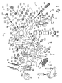
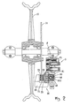
- a hydraulic disc brake device in accordance with the present invention is installed on a wheel carrier 10 and serves to cooperate with the brake disc 11, which comprises: a base assembly G, a sliding assembly H, a spring assembly S and a positioning board F. Oil W circulates within the base assembly G.
- the positioning board F is fixed on the wheel carrier 10 by screws, and two positioning bolts F1 are screwed in the positioning board F.
- the base assembly G is positioned on the wheel carrier 10 by the positioning board F and essentially comprises: a pressing device 20, a first arc-shaped track 30, a second arc-shaped track 40, and a control valve assembly 50.
- the pressing device 20 includes an oil chamber 21, a piston 22, two oil seals 23, 24, a steel-ball positioning disc 25 and a plurality of steel balls 26.
- a positioning arm 28 protrudes from a side of the pressing device 20 and is to be positioned on one of the positioning bolts F1 by a hollow positioning sleeve 281.
- the oil seals 23 and 24 are disposed in the oil chamber 21, and the piston 22 is moveably sealed in the oil chamber 21 by the oil seals 23 and 24.
- the oil pressure of the oil chamber 21 serves to push the piston 22, the piston 22 is defined in its outer edge with an engaging groove 221, and the steel-ball positioning disc 25 is formed around its outer periphery with a protrusive engaging edge 251 to be engaged in the engaging groove 221.
- the plurality of steel balls 26 is positioned between the steel-ball positioning disc 25 and the piston 22.
- a plurality of through holes 252 is defined in the steel-ball positioning disc 25, and the respective steel balls 26 partially protrude from the through holes 252.
- An exhaust valve 27 is disposed adjacent to the oil chamber 21.
- the first arc-shaped track 30 is located correspondingly to the center of the brake disc 11 and is disposed at a side of the pressing device 20, and an end of the first arc-shaped track 30 is positioned on another one of the positioning bolts F1 by a hollow positioning sleeve 31.
- the first arc-shaped track 30 is covered with a wear-resistance cover 32.
- the second arc-shaped track 40 is located correspondingly to the center of the brake disc 11 and is square in cross section.
- a hole 41 is defined in the second arc-shaped track 40 and is located along the length thereof, and the second arc-shaped track 40 is located at another side of the pressing device 20 and also covered with a wear-resistance cover 42.
- a safety oil passage 43 is formed in the bottom of the hole 41 and is in communication with the oil chamber 21 of the pressing device 20.
- the control valve assembly 50 includes a control groove 51, a control rod 52, a relief valve 53, a main passage 54, an auxiliary passage 55 and a pressure relief space 56.
- the control groove 51 is located adjacent to the oil chamber 21 of the pressing device 20.
- a guide cover 511 with a central hole 513 and a dust-proof ring 512 is screwed to either side of the control groove 51. Both ends of the control rod 52 are protruded out of the center hole 513 of the two guide covers 511.
- the control groove 51 is connected to the oil chamber 21 of the pressing assembly via the main passage 54 and the pressure relief space 56, and the auxiliary passage 55 is connected to the safety oil passage 43 of the second arc-shaped track 40.
- a sealing screw 542 cooperating with a sealing ring 541 is disposed opposite the main passage 54. Located opposite the auxiliary passage 55 is an oil feeding hole 551.
- the relief valve 53 includes a pressure relief steel ball 531, a pin 532 and a spring 533 disposed in the pressure relief space 56, respectively.
- a sealing screw 57 with a sealing ring 571 is disposed beside the pressure relief space 56.
- the pin 532 is to be pressed against the spring 533 and the oil pressure of the oil chamber 21.
- the pressure relief steel ball 531 is located in the control groove 51, and the pin 532 is sealed between the oil chamber 21 and the control groove 51 together with a first sliding bush 534, an oil seal 535, a second sliding bush 536 and an dust-proof cover 537.
- a plurality of oil seals 521, a first oil ring 522, a second oil ring 523 and a sliding bush 59 are positioned in the mid section of the control groove 51 by a C ring 58.
- the first and second oil rings 522 and 523 each is formed with an open guiding structure for guiding oil out from inside.
- the first oil ring 522 is located correspondingly to the main passage 54, and the second oil ring 523 is located correspondingly to the auxiliary passage 55.
- the control rod 52 is formed with a control passage 524, and an oil seal 526 and a sealing screw 525 are screwed in the end of the control passage 524.
- a first oil hole 527 and a second oil hole 528 are formed in the control passage 524 and are located correspondingly to the first oil ring 522 and the second oil ring 523, respectively.
- An annular neck portion 529 is formed on the control rod 52 and is located correspondingly to the pressure relief space 56, and the pressure relief steel ball 531 of the pressure relief valve 53 is to be engaged in and disengaged from the annular neck portion 529.
- a pressure relief oil space B will appear at another end of the pin 532 opposite the pressure relief steel ball 531.
- the sliding assembly H is slideably disposed on the first arc-shaped track 30 and the second arc-shaped track 40 of the base assembly G and includes a seat 60, a brake lining assembly 70 and a sliding device 80.
- the seat 60 includes a first positioning portion 61 and a second positioning portion 62 located correspondingly to the first and the second arc-shaped tracks 30 and 40 of the base assembly G.
- a stop portion 63 is formed at the end of the second positioning portion 62.
- An anti-collision piece 631 is fixed on the stop portion 63 by screws 632.
- a screw 633 is disposed at the center of the stop portion 63 and the anti-collision piece 631.
- Formed between the first and second positions 61 and 62 is an elliptical sliding hole 64 for passage of the piston 22 of the pressing device 20 and the flange G1 of the base assembly G.
- a stepped recess 641 is formed at a side of the elliptical sliding hole 64, and an anti-collision block 642 and a fixing piece 644 are fixed in the stepped recess 641 by screws 643.
- a brake-mounting portion 65 protrudes from the seat 60 and is located around the elliptical sliding hole 64, so that a brake space 66 is defined between the brake-mounting portion 65 and the elliptical sliding hole 64 for accommodation of the brake disc 11 and the brake lining assembly 70. Screwed on the brake-mounting portion 65 are two brake-lining positioning shafts 651, and the two brake-lining positioning shafts 651 are inserted in the seat 60 and located at both sides of the elliptical sliding hole 64.
- the brake-mounting portion 65 is provided with an engaging rib 652 located in the brake space 66.
- Two opposite abutting blocks 67 are arranged at a side of the elliptical sliding hole 64, and each of which is provided with an abutting screw 671 and an auditing nut 672. The two abutting blocks 67 are pressed against both ends of the control rod 52 of the control valve assembly 50.
- the brake lining assembly 70 includes a front brake lining shoe 71 and a rear brake lining shoe 72 that are inserted on the two brake-lining positioning shafts 651 in a parallel manner, and with the brake-lining positioning shafts 651, the front brake lining shoe 71 and the rear brake lining shoe 72 can move within the brake space 66.
- a pressing spring leaf 73 is disposed against a side of the front brake lining shoe 71 and the rear brake lining shoe 72 and is positioned on the engaging rib 652 of the brake-mounting portion 65 of the seat 60, thus preventing the front brake lining shoe 71 and the rear brake lining shoe 72 from becoming loose.
- the front surface of the front brake lining shoe 71 is pressed against the steel balls 26 on the steel ball positioning disc 25 of the piston 22 of the pressing device 20, and can move smoothly under the aid of the steel balls 26 protruding from the steel ball positioning disc 25.
- the sliding device 80 includes inverted U-shaped seats 81, dust-proof frames 82 and wear-resistance pieces 83 assembled together by screws.
- the inverted U-shaped seats 81 are fixed on the first and second positioning portions 61 and 62 of the seat 60 by rivets 85.
- the inner space of the inverted U-shaped seats 81 and the radian thereof are designed to allow the inverted U-shaped seats 81 to be slideably mounted on the first and second arc-shaped tracks 30 and 40.
- a plurality of cavities 811 with steel balls 812 are formed in the surface of each of the inverted U-shaped seats 81, and the steel balls 812 are located between the inner surface of the inverted U-shaped seat 81 and the wear-resistance cover 32 and 42.
- the respective dust-proof frame 82 is fixed to the lateral edge of the inverted U-shaped seat 81 by screws 84, so as to prevent dust entering the arc-shaped tracks.
- the inverted U-shaped seats 81 the seat 60 is able to slide stably relative to the first and second arc-shaped tracks 30 and 40.
- the spring assembly S is confined in the hole 41 of the second arc-shaped track 40 by the anti-collision piece 631 and the screw 633 of the stop portion 63 of the sliding assembly H, and includes a safety rod 90, two seal rings 91, a safety spring 92, a support bracket 93, a washer 94 and a return spring 95.
- One end of the return spring 95 cooperating with the washer 94 and the support bracket 93 is pressed against the bottom of the hole 41 of the second arc-shaped track 40, and another end of the return spring 95 is positioned on the screw 633 of the seat 60.
- the return spring 95 serves to push against the stop portion 63 of the sliding assembly H.
- the safety spring 92 is restricted in the support bracket 93 and the return spring 95, and the safety rod 90 is riveted to the support bracket 93.
- the safety rod 93 and the return spring 95 push the safety rod 90 to move, so as to close the safety oil passage 43 of the second arc-shaped track 40.
- the brake disc 11 rotates counterclockwise along with the wheel, the front brake lining shoe 71 and the rear brake lining shoe 72 are located at both sides of the brake disc 11 in a pressure free manner.
- the return spring 95 is biased between the hole 41 of the second arc-shaped track 40 of the base assembly G and the anti-collision piece 631 of the stop portion 63 of the sliding assembly H, the motionless base assembly G on the wheel carrier 10 enables the sliding assembly H to be pushed by the return spring 95 to the lowest portion of the arc-shaped track.
- the two opposite abutting blocks 67 of the sliding assembly H are also located at the lowest portion of the arc-shaped track, and push the lower end of the control rod 52 of the control valve assembly 50 upward. Since the control rod 52 moves with respect to the control groove 51 of the control valve assembly 50, the control passage 524 of the control rod 52 will be aligned to the first oil hole 527, and the second oil hole 528 and the second oil ring 523 will exactly be aligned to the oil feeding hole 551. As a result, the oil W from the oil feeding hole 551 will flow to the oil chamber 21 via the second oil ring 523, the second oil hole 528, the control passage 524, the first oil hole 527, the first oil ring 522 and the main passage 54. However, before the oil W pressure increases, the piston 22 will not be driven by any force from the oil pressure of the oil chamber 21.
- the sliding assembly H doesn't move relative to the base assembly G, therefore, the front surface of the front brake lining shoe 71 is not pressed against the steel balls 26 on the steel ball positioning disc 25 of the piston 22 of the pressing device 20.
- the brake lining assembly 70 doesn't clamp the brake disc 11, and the annular neck portion 529 of the control rod 52 is located below the pressure relief steel ball 531 of the pressure relief valve 53. Therefore, the wheel can rotate freely without any resistance.
- the piston 22 of the pressing assembly 20 is driven to move by the oil pressure from the oil chamber 21, pushing the front brake lining shoe 71 toward the rear brake lining shoe 72, as a result, the brake disc 11 is clamped firmly by the front brake lining shoe 71 and the rear brake lining shoe 72, causing an emergency braking action.
- the front brake lining shoe 71 and the rear brake lining shoe 72 absorb a lot of counterclockwise stress from the brake disc 11, generating a very large counterclockwise stress toward the center of the brake disc 11.
- the sliding assembly H is slideably disposed in the first and second arc-shaped tracks 30 and 40 of the base assembly G, the first and second arc-shaped tracks 30 and 40 are located opposite the center of the brake disc 11, plus the inertial force produced by an emergency of a high speed vehicle is larger than the critical value of the elastic force of the return spring 95 of the spring assembly S.
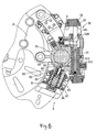
- the emergency-brake caused stress will push the sliding assembly H to slide counterclockwise while compressing the return spring 95 (as shown in Fig. 5 ).
- the elliptical sliding hole 64 is formed between the first and second positions 61 and 62for passage of the piston 22 of the pressing device 20 and the flange G1 of the base assembly G, plus the front surface of the front brake lining shoe 71 is pressed against the steel balls 26 on the steel ball positioning disc 25 of the piston 22 of the pressing device 20, and can move smoothly under the aid of the steel balls 26 protruding from the steel ball positioning disc 25.
- the steel balls 812 the inverted U-shaped seats 81, the seat 60 is able to slide stably relative to the wear resistance covers 32 and 42 of the base assembly G.
- the counterclockwise motion of the slide assembly H causes its displacement with respect to the base assembly G, and the abutting blocks 67 of the sliding assembly H push the control rod 52 of the control valve assembly 50 to move, so that the control groove 51 of the control valve assembly 50 changes with the upward movement of the control rod 52, and the first and second oil rings 522 and 523 are not aligned with the main passage 54 and the auxiliary passage 55 anymore. Therefore, the oil W stops flowing into the oil chamber 21. At this moment, the control rod 52 of the control valve assembly 50 moves upward, therefore, the annular neck portion 529 of the control rod 52 moves upward to a position aligned with the pressure relief steel ball 531.
- the sliding assembly H rotates about the base assembly G.
- the annular neck portion 529 of the control rod 52 moves downward (to disengage from the pressure relief steel ball 531 again), the pressure relief steel ball 531 pushes the pin 532 and the spring 533 backward, so that the pressure relief oil space B disappears.
- the control groove 51 of the control valve assembly 50 changes with the downward movement of the control rod 52, and the first and second oil rings 522 and 523 are aligned with the main passage 54 and the auxiliary passage 55 again. Therefore, the oil W flows into the oil chamber 21 again (the pressure thereof increases again), and the brake lining assembly 70 clamps the brake disc 11 again instantly. Such instant clamping and instant relief actions will occur repeatedly, preventing the brake disc from being clamped too tight (antilock effect).
- a plurality of anti-collision structures are provided on the sliding assembly H and opposite the base assembly G, wear-resistance structures are arranged at the positions where the friction frequently occurs, and the present invention is also provided with a plurality of position adjustment structures.
- wear-resistance structures are arranged at the positions where the friction frequently occurs, and the present invention is also provided with a plurality of position adjustment structures.
- the present invention is particularly designed to have the safety rod 90, the safety spring 92 and the support bracket 93. Please refer to the following descriptions:
- Figs. 8 and 9 show a second embodiment.
- the two oil chambers 21 are in communication with each other via a main passage 54.
- An exhaust valve 27 is arranged beside the oil chamber 21, and a safety oil passage 43 is formed beside the oil chamber 21a.
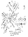
- Fig. 10 shows a third embodiment of the present invention, this embodiment is additionally provided with a main cylinder C3 and an elastic oil-storage cylinder C31.
- the seat C1 is installed on the wheel carrier 10 and serves to cooperate with the moveable base assembly C2.
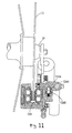
- the status of the hydraulic disc brake device of this embodiment before braking action is shown in Figs. 11-14
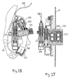
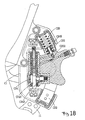
- the of the hydraulic disc brake device of this embodiment during braking action is shown in Figs. 15-18
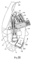
- the status of the hydraulic disc brake device of this embodiment during antilock action is shown in Figs. 19-21 .
- the main structures of this embodiment are explained as follows:
- the base assembly C2 includes a pressing device C21, a first arc-shaped track C22, a second arc-shaped track C23, a control valve assembly C24, a spring assembly C25, the main cylinder C3 and the elastic oil-storage cylinder C31.
- the spring assembly C25 is confined in the first arc-shaped track C22 by the sliding assembly C12, and includes a safety rod, two seal rings, a safety spring, a support bracket, a washer and a return spring (these components are assembled, function in the same manner of the previous embodiment, so further explanations will be omitted here).
- One end of the return spring cooperating with the washer and the support bracket is pressed against the bottom edge of the first arc-shaped track, and another end of the return spring is pressed against the sliding members C12 of the seat C1.
- the safety spring is restricted in the support bracket and the return spring, and the safety rod is riveted to the support bracket.
- the pressing device C21 includes a piston C211, and a plurality of oil seals C212. Since the pressing device C21 moves along with the base assembly C2 and the braking lining assembly C26, it doesn't need the steel balls and the steel-ball positioning disc, and it can use the conventional pressing device to cooperate with the brake lining assembly C26, and the brake lining assembly C26 is pressed to clamp the brake disc 11.
- the first and second arc-shaped tracks C22 and C23 are also provided with the wear-resistance covers C221, C231, the sling members C12 are slideably installed on the first and second arc-shaped tracks C22 and C23.
- An antic-collision cushion C232 is disposed at the end of the second arc-shaped track C23, and the first arc-shaped track C22 is interiorly formed with safety oil passage.
- the end of the safety rod of the spring assembly C25 is pushed by the return spring to close the safety oil passage (these components are assembled, function in the same manner of the previous embodiment, so further explanations will be omitted here).
- control valve assembly C24 The assembly, function and effect of the control valve assembly C24 are similar to the previous embodiment, and the only difference is that the position and the structure of the oil route are changed appropriately.
- the control groove C241, the control rod C242, the pressure relief valve C243, the main passage C244, the auxiliary passage C245, and the pressure relief space C246 still function in the same way as the previous embodiment.
- main cylinder C3 and the elastic oil-storage cylinder C31 are installed on the base assembly C2 directly.
- the main cylinder C3 utilizes a steel cord C32 to drive the main piston C33, so as to push the oil into the oil chamber.
- a pushing spring C34, an O-shaped ring C36, and a piston C35 are sealed in the elastic oil-storage cylinder C31 by a cover C37.
- the pushing spring C34 pushes the piston C35 to move, so as to push the oil into the main cylinder C3, and the oil pressure of the main cylinder C3 is directly connected to the control valve assembly C24.
- the seat C1 is changed to be mounted on the wheel carrier 10 and is used to cooperate with the moveable base assembly C2, and the components used and the theory thereof are the same as the previous embodiment. Furthermore, by pulling the steel cord C32, the main cylinder C3 will push the oil from the elastic oil-storage cylinder C31 into the control valve assembly C24, thus creating an antilock function while preventing the occurrence of instability when an emergency brake is applied to a high speed vehicle.
- the main cylinder in addition to controlling the main cylinder C3 by pulling the steel cord C32, the main cylinder can also be mounted on the handlebar, by pulling the brake bard on the handlebar, the main piston of the main cylinder will be caused to push the oil into the control valve assembly via the oil route. This method is also made without departing from the scope of the present invention.
- the hydraulic disc brake device in accordance with the present invention has the characteristics and functions:
Landscapes
- Engineering & Computer Science (AREA)
- Mechanical Engineering (AREA)
- General Engineering & Computer Science (AREA)
- Transportation (AREA)
- Braking Arrangements (AREA)
Claims (20)
- Fahrzeug mit einer hydraulischen Scheibenbremsvorrichtung, umfassend:eine Basisbaugruppe (G), die am Fahrzeug montiert ist;eine Gleitbaugruppe (H), die entlang einem vorbestimmten bogenförmigen Weg an der Basisbaugruppe (G) gleitbar montiert ist;eine Rückstellfeder (95), die zwischen der Basisbaugruppe (G) und der Gleitbaugruppe (H) angeordnet ist, wobei eine Relativbewegung zwischen der Basisbaugruppe (G) und der Gleitbaugruppe (H) eine Kompression der Rückstellfeder (95) hervorruft;eine Bremsbelaganordnung (70), die zum Einklemmen einer Bremsscheibe (11) eingesetzt und durch Öldruck eines Öldrucksystems des Fahrzeugs gesteuert wird; unddadurch gekennzeichnet,- eine Regelventilanordnung (50), die zwischen dem Öldrucksystem angeordnet ist, um den Öldruck des Öldrucksystems zu regeln;
dass eine auf die Bremsbelaganordnung (70) ausgeübte Massenkraft beim Bremsen die Gleitbaugruppe (H) dazu veranlasst, sich entlang dem vorbestimmten bogenförmigen Weg in Beziehung zur Basisbaugruppe (G) zu verschieben, wobei die Relativbewegung zwischen der Gleitbaugruppe (H) und der Basisbaugruppe (G) eine Kompression der Rückstellfeder (95) hervorrtuft und die Regelventilanordnung (50) dazu bringt, mit dem Erhöhen des Öldrucks aufzuhören, wobei die Regelventilanordnung (50) einen Druckentlastungsölraum (B) in der Basisbaugruppe (G) herbeischafft, wobei die Rückstellfeder (95), nachdem die Bremsbelaganordnung (70) die Bremsscheibe (11) freigibt, den Druckentlastungsölraum (B) wieder schließen wird, wodurch der Öldruck wieder erhöht wird, so dass der Bremsbelaganordnung (70) gestattet wird, die Bremsscheibe (11) wiederholt einzuklemmen und freizugeben. - Fahrzeug mit einer hydraulischen Scheibenbremsvorrichtung nach Anspruch 1,
dadurch gekennzeichnet,
dass die Basisbaugruppe (G) an einem Radträger (10) des Fahrzeugs montiert ist und eine bogenförmige Schiene (30) und eine zweite bogenförmige Schiene (40) umfasst, wobei die Regelventilanordnung (50) in der Basisbaugruppe (50) eingebaut ist und die Gleitbaugruppe (H) gleitbar auf der ersten und der zweiten bogenförmigen Schiene (30, 40) der Basisbaugruppe (G) angeordnet ist. - Fahrzeug mit einer hydraulischen Scheibenbremsvorrichtung nach Anspruch 2,
dadurch gekennzeichnet,
dass die erste bogenförmige Schiene (30) entsprechend dem Kreismittelpunkt der Bremsscheibe (11) und die zweite bogenförmige Schiene (40) entsprechend dem Kreismittelpunkt der Bremsscheibe (11) angeordnet sind, wobei die zweite bogenförmige Schiene (40) mit einem Loch (41) in ihrer Längsrichtung ausgebildet ist; und
dass die Gleitbaugruppe (H) einen Sitz (60), die Bremsbelaganordnung (70) und eine Gleitvorrichtung (80) umfasst, wobei ein Bremsraum (66) im Sitz (60) abgegrenzt ist und zur Aufnahme der Bremsscheibe (11) und der Bremsbelaganordnung (70) dient, wobei die Gleitvorrichtung (80) auf dem Sitz (60) angebaut ist, wobei dier erste und die zweite bogenförmige Schiene (30, 40) gleitbar auf der Gleitvorrichtung (80) montiert sind. - Fahrzeug mit einer hydraulischen Scheibenbremsvorrichtung nach Anspruch 3,
dadurch gekennzeichnet,
dass die Basisbaugruppe (G) mit einem Flansch (G1) ausgebildet ist und eine Pressanordnung (20) umfasst, die einen Kolben (22) umfasst, der in einer Ölkammer (21) verschiebbar abgedichtet ist, wobei der Öldruck der Ölkammer (21) zum Drücken des Kolbens (22) dient, wobei ein Sicherheits-Öldurchgang (43) in einem Boden des Loches (41) der zweiten bogenförmigen Schiene (40) ausgebildet ist und mit der Ölkammer (21) der Pressanordnung (20) kommuniziert;
dass im Kreismittelpunkt des Sitzes (60) der Gleitbaugruppe (H) ein elliptisches Gleitloch (64) ausgebildet ist, das der Kolben (22) der Pressanordnung (20) und der Flansch (G1) der Basisbaugruppe (G) passieren können, wobei ein Bremsträger (65) vom elliptischen Gleitloch (64) des Sitzes (64) vorsteht, wobei der Bremsraum (66) zwischen dem Bremsträger (65) und dem elliptischen Gleitloch (64) abgegrenzt ist; und
dass die Bremsbelaganordnung (70) einen vorderen Bremsbelag (71) und einen hinteren Bremsbelag (72) umfasst, die auf dem Sitz (60) parallel zueinander angeordnet sind, wobei eine vordere Oberfläche des vorderen Bremsbelags (71) gegen den Kolben (22) der Pressanordnung (20) gedrückt wird. - Fahrzeug mit einer hydraulischen Scheibenbremsvorrichtung nach Anspruch 3,
dadurch gekennzeichnet,
dass ein Sicherheits-Öldurchgang (43) in einem Boden des Loches (41) der zweiten bogenförmigen Schiene (40) ausgebildet ist und mit der Ölkammer (21) der Pressanordnung (20) kommuniziert;
dass ein Sperrteil (63) auf dem Sitz (60) der Gleitbaugruppe (H) ausgebildet und entsprechend der zweiten bogenförmigen Schiene (40) der Basisbaugruppe (G) angeordnet ist; und
dass die Rückstellfeder (95) zwischen einem Boden des Loches (41) der zweiten bogenförmigen Schiene 840) der Basisbaugruppe (G) und dem Sperrteil (63) der Gleitbaugruppe (H) vorgespannt ist. - Fahrzeug mit einer hydraulischen Scheibenbremsvorrichtung nach Anspruch 3,
dadurch gekennzeichnet,
dass die Gleitvorrichtung (80) Sitze (81) in Form eines umgedrehten U, staubdichte Rahmen (82) und verschleißfeste Scheiben (83) umfasst, die mittels Schrauben miteinander zusammengebaut sind, wobei die Sitze (81) in Form eines umgedrehten U mittels Nieten (85) am Sitz (60) fixiert sind, wobei ein Innenraum der Sitze (81) in Form eines umgedrehten U und ein Bogenmaß des Innenraums konzipiert sind, um den Sitzen (81) in Form eines umgedrehten U zu ermöglichen, auf der ersten und der zweiten bogenförmigen Schiene (30, 40) montiert zu werden. - Fahrzeug mit einer hydraulischen Scheibenbremsvorrichtung nach Anspruch 4,
dadurch gekennzeichnet,
dass eine abgesetzte Aussparung (641) ist an einer Seite des elliptischen Loches (64) ausgebildet ist und ein Antikollisionsblock (642) mittels Schrauben in der abgesetzten Aussparung (641) fixiert ist, um dem Flansch (G1) der Basisbaugruppe (G) vor Aufprall zu bewahren. - Fahrzeug mit einer hydraulischen Scheibenbremsvorrichtung nach Anspruch 4,
dadurch gekennzeichnet,
dass die Pressanordnung (20) eine Ölkammer (21), den Kolben (22), Öldichtungen (23), eine Stahlkugel-Positionierscheibe (25) und eine Vielzahl von Stahlkugeln (26) umfasst, wobei der Kolben (22) durch die Öldichtungen (23) verschiebbar in der Ölkammer (21) abgedichtet ist, wobei die Stahlkugel-Positionierscheibe (25) an einem Ende des Kolbens (22) positioniert ist, wobei die Vielzahl von Stahlkugeln (26) zwischen der Stahlkugel-Positionierscheibe (25) und dem Kolben (22) positioniert ist, wobei eine Vielzahl von Durchgangslöchern (252) in der Stahlkugel-Positionierscheibe (25) abgegrenzt ist, wobei die jeweiligen Stahlkugeln (26) teilweise aus den Durchgangslöchern (252) herausgucken; und dass die vordere Oberfläche des hinteren Bremsbelags (71) gegen die Stahlkugeln (26) auf der Stahlkugel-Positionierscheibe (25) des Kolbens (22) der Pressanordnung (20) gedrückt wird und sich mithilfe der aus der Stahlkugel-Positionierscheibe (25) herausguckenden Stahlkugeln (26) gleichmäßig verschieben kann. - Fahrzeug mit einer hydraulischen Scheibenbremsvorrichtung nach Anspruch 5,
dadurch gekennzeichnet,
dass der Sitz (60) ein zweites Positionierteil (62) umfasst, das entsprechend der zweiten bogenförmigen Schiene (40) der Basisbaugruppe (G) angeordnet ist, wobei das Sperrteil (63) am Ende des zweiten Positionierteils (62) ausgebildet ist, wobei eine Antikollisionsscheibe (631) mittels Schrauben am Sperrteil (63) fixiert ist, wobei eine Schraube in der Mitte des Sperrteils (63) und der Antikollisionsscheibe (631) angeordnet ist. - Fahrzeug mit einer hydraulischen Scheibenbremsvorrichtung nach Anspruch 5,
dadurch gekennzeichnet,
dass die Regelventilanordnung (50) einen Steuerkanal (51), einen Steuerstab (52), ein Abblasventil (53), einen Hauptdurchgang (54), einen Nebendurchgang (55) und einen Druckentlastungsraum (56) umfasst, wobei sich der Steuerkanal (51) nahe der Ölkammer (21) der Pressanordnung (20) befindet, wobei an den beiden Seiten des Steuerkanals (51) jeweils eine Führungsabdeckung (511) mit einem Zentralloch (513) angeordnet ist, wobei die beiden Enden des Steuerstabs (52) jeweils aus dem Zentralloch (513) der Führungsabdeckung (511) herausgucken, wobei der Steuerkanal (51) über den Hauptdurchgang (54) und den Druckentlastungsraum (56) mit der Ölkammer (21) der Pressanordnung (20) verbunden ist;
dass der Nebendurchgang (55) mit dem Sicherheits-Öldurchgang (43) der zweiten bogenförmigen Schiene (40) verbunden ist;
dass das Abblasventil (53) eine Druckentlastungsstahlkugel (531), einen Pin (532) und eine Feder (533) umfasst, die im Druckentlastungsraum (56) angeordnet sind, wobei der Pin (532) durch die Feder (533) und den Öldruck der Ölkammer (21) gedrückt wird, wobei die Druckentlastungsstahlkugel (531) im Steuerkanal (51) angeordnet ist, wobei der Pin (532) zwischen der Ölkammer (21) und dem Steuerkanal (51) gleitbar abgedichtet ist; und
dass ein erster Ölring (522) und ein zweiter Ölring (523) im mittleren Abschnitt des Steuerkanals (51) positioniert sind, wobei der erste und der zweite Ölring (522, 523) jeweils mit einer offenen Führungsstruktur ausgebildet sind, wobei der erste Ölring (522) entsprechend dem Hauptdurchgang (54) und der zweite Ölring (523) entsprechend dem Nebendurchgang (55) angeordnet sind, wobei der Steuerstab (52) in den Steuerkanal (51) eingesetzt und mit einem Steuerdurchgang (524) ausgebildet ist, wobei ein erstes Ölloch (527) und ein zweites Ölloch (528) im Steuerdurchgang (524) ausgebildet und jeweils entsprechend dem ersten und dem zweiten Ölring (522, 523) angeordnet sind, wobei eine Einschnürung (529) am Steuerstab (52) ausgebildet und entsprechend dem Druckentlastungsraum (56) angeordnet ist, wobei die Druckentlastungsstahlkugel (531) des Abblasventils (53) mit der Einschnürung (529) in Eingriff und außer Eingriff gebracht werden kann, wobei beim Eintreten der Druckentlastungsstahlkugel (531) in die Einschnürung (529) ein Druckentlastungsölraum (B) am anderen Ende des Pins (532), nämlich an dem der Druckentlastungsstahlkugel (531) gegenüberstehenden Ende, erscheint. - Fahrzeug mit einer hydraulischen Scheibenbremsvorrichtung nach Anspruch 9,
dadurch gekennzeichnet,
dass ferner eine Federanordnung (533) vorgesehen ist, die durch das Sperrteil (63) der Gleitbaugruppe (H) im Loch (41) der zweiten bogenförmigen Schiene (40) begrenzt ist, wobei die Federanordnung (533) eine Rückstellfeder (95) umfasst. - Fahrzeug mit einer hydraulischen Scheibenbremsvorrichtung nach Anspruch 10,
dadurch gekennzeichnet,
dass auf die beiden Seiten des Steuerkanals (51) jeweils eine ein Zentralloch (513) und einen staubdichten Ring aufweisende Führungsabdeckung (511) aufgeschraubt ist, wobei die beiden Enden des Steuerstabs (52) aus dem Zentralloch der beiden Führungsabdeckungen (511) herausgucken. - Fahrzeug mit einer hydraulischen Scheibenbremsvorrichtung nach Anspruch 11,
dadurch gekennzeichnet,
dass die Federanordnung (S) einen Sicherheitsstab (90), eine Sicherheitsfeder (92), einen Stützwinkel (93) und die Rückstellfeder (95) umfasst, wobei ein mit dem Stützwinkel (93) zusammenwirkendes Ende der Rückstellfeder (95) gegen den Boden des Loches (41) der zweiten bogenförmigen Schiene (40) und das andere Ende der Rückstellfeder (95) gegen das Sperrteil (63) der Gleitbaugruppe (H) gedrückt werden, wobei die Sicherheitsfeder (92) im Stützwinkel (93) eingeschränkt ist, wobei der Sicherheitsstab (90) im Stützwinkel (93) angeordnet ist und durch den Stützwinkel (93) sowie die Rückstellfeder (95) derart gedrückt wird, dass er sich bewegt, um den Sicherheits-Öldurchgang (43) der zweiten bogenförmigen Schiene (40) zu verschließen. - Fahrzeug mit einer hydraulischen Scheibenbremsvorrichtung, umfassend:- einen Sitz (C1), der an einem Radträger (10) montiert ist und zwei Gleitelemente (C12) aufweist, die in einem vorbestimmten bogenförmigen Weg angeordnet sind;- eine Basisbaugruppe (C2), die gleitbar in den Gleitelementen (C12) des Sitzes (C1) montiert ist;- eine Rückstellfeder, die zwischen der Basisbaugruppe (C2) und dem Sitz (C1) angeordnet ist, wobei eine Relativbewegung zwischen der Basisbaugruppe (C2) und dem Sitz (C1) eine Kompression der Rückstellfeder hervorruft;- eine Bremsbelaganordnung, die zum Einklemmen einer Bremsscheibe (11) eingesetzt und durch Öldruck eines Öldrucksystems des Fahrzeugs gesteuert wird; und- eine Regelventilanordnung (C24), die zwischen dem Öldrucksystem angeordnet ist, um den Öldruck des Öldrucksystems zu regeln;dadurch gekennzeichnet,
dass eine auf die Bremsbelaganordnung ausgeübte Massenkraft beim Bremsen die Basisbaugruppe (C2) dazu veranlasst, sich entlang dem vorbestimmten bogenförmigen Weg in Beziehung zum Sitz (C1) zu verschieben, wobei die Relativbewegung zwischen dem Sitz (C1) und der Basisbaugruppe (C2) eine Kompression der Rückstellfeder hervorruft und die Regelventilanordnung (C24) dazu bringt, mit dem Erhöhen des Öldrucks aufzuhören, wonach die Regelventilanordnung (C24) einen Druckentlastungsölraum in der Basisbaugruppe (C2) öffnet, wobei die Rückstellfeder, nachdem die Bremsbelaganordnung die Bremsscheibe (11) freigibt, den Druckentlastungsölraum wieder schließen wird, wodurch der Öldruck wieder erhöht wird, so dass der Bremsbelaganordnung gestattet wird, die Bremsscheibe (11) wiederholt einzuklemmen und freizugeben. - Fahrzeug mit einer hydraulischen Scheibenbremsvorrichtung nach Anspruch 14,
dadurch gekennzeichnet,
dass die Basisbaugruppe (C2) eine Pressanordnung (C21), eine erste bogenförmige Schiene (C22) und eine zweite bogenförmige Schiene (C23) umfasst, wobei die Pressanordnung (C21) durch Drücken eines Hauptzylinders (C3) geschoben wird, wobei die erste bogenförmige Schiene (C22) im Sitz (C1) gleitbar angeordnet und mit einer Federanordnung (C25) und einem Sicherheits-Öldurchgang versehen ist, wobei die zweite bogenförmige Schiene (C23) im Sitz (C1) gleitbar angeordnet ist. - Fahrzeug mit einer hydraulischen Scheibenbremsvorrichtung nach Anspruch 14,
dadurch gekennzeichnet,
dass die Regelventilanordnung (C24) einen Steuerkanal (C241), einen Steuerstab (C242), ein Abblasventil (C243), einen Hauptdurchgang (C244), einen Nebendurchgang (C245) und einen Druckentlastungsraum (C246) umfasst, wobei sich der Steuerkanal (C241) nahe der Ölkammer der Pressanordnung (C21) befindet, wobei an den beiden Seiten des Steuerkanals (C241) jeweils eine Führungsabdeckung mit einem Zentralloch angeordnet ist, wobei die beiden Enden des Steuerstabs (C242) jeweils aus dem Zentralloch der Führungsabdeckung herausgucken, wobei der Steuerkanal (C241) über den Hauptdurchgang (C244) und den Druckentlastungsraum (C246) mit der Ölkammer der Pressanordnung (C21) verbunden ist; dass der Nebendurchgang (C245) mit dem Sicherheits-Öldurchgang der ersten bogenförmigen Schiene (C22) verbunden ist, wobei ein Öleinspeisungsloch gegenüber dem Nebendurchgang (C245) angeordnet ist;
dass ein erster Ölring und ein zweiter Ölring im mittleren Abschnitt des Steuerkanals (C241) positioniert sind, wobei der erste und der zweite Ölring jeweils mit einer offenen Führungsstruktur ausgebildet sind, wobei der erste Ölring entsprechend dem Hauptdurchgang (C244) und der zweite Ölring entsprechend dem Nebendurchgang (C245) angeordnet sind, wobei der Steuerstab (C242) mit einem Steuerdurchgang ausgebildet ist, wobei ein erstes Ölloch und ein zweites Ölloch im Steuerdurchgang ausgebildet und jeweils entsprechend dem ersten und dem zweiten Ölring angeordnet sind, wobei eine Einschnürung am Steuerstab (C242) ausgebildet und entsprechend dem Druckentlastungsraum (C246) angeordnet ist, wobei die Druckentlastungsstahlkugel des Abblasventils (C243) mit der Einschnürung in Eingriff und außer Eingriff gebracht werden kann, wobei beim Eintreten der Druckentlastungsstahlkugel in die Einschnürung ein Druckentlastungsölraum am anderen Ende des Pins, nämlich an dem der Druckentlastungsstahlkugel gegenüberstehenden Ende, erscheint. - Fahrzeug mit einer hydraulischen Scheibenbremsvorrichtung nach Anspruch 15,
dadurch gekennzeichnet,
dass die Basisbaugruppe (C2) eine Pressanordnung (C21) umfasst, die einen Kolben (C211) umfasst, der in einer Ölkammer verschiebbar abgedichtet ist, wobei der Öldruck der Ölkammer zum Drücken des Kolbens (C211) dient, wobei ein Loch in der ersten bogenförmigen Schiene (C22) ausgebildet ist, wobei ein Sicherheits-Öldurchgang in einem Boden des Loches ausgebildet ist und mit der Ölkammer der Pressanordnung (C21) kommuniziert;
dass der Sitz (C1) am Radträger (10) angebaut ist; und
dass die Bremsbelaganordnung einen vorderen Bremsbelag und einen hinteren Bremsbelag umfasst, die auf der Basisbaugruppe (C2) montiert sind, wobei eine vordere Oberfläche des vorderen Bremsbelags gegen den Kolben (C211) der Pressanordnung (C21) gedrückt wird. - Fahrzeug mit einer hydraulischen Scheibenbremsvorrichtung nach Anspruch 15,
dadurch gekennzeichnet,
dass die Federanordnung (C25) durch das Gleitelement (C12) des Sitzes (C1) im Loch der ersten bogenförmigen Schiene (C22) begrenzt ist und die Rückstellfeder umfasst. - Fahrzeug mit einer hydraulischen Scheibenbremsvorrichtung nach Anspruch 16,
dadurch gekennzeichnet,
dass das Abblasventil (C243) eine Druckentlastungsstahlkugel, einen Pin und eine Feder umfasst, die jeweils im Druckentlastungsraum (C246) angeordnet sind, wobei der Pin durch die Feder und den Öldruck der Ölkammer gedrückt wird, wobei die Druckentlastungsstahlkugel im Steuerkanal (C241) angeordnet ist, wobei der Pin zwischen der Ölkammer und dem Steuerkanal (C241) gleitbar abgedichtet ist. - Fahrzeug mit einer hydraulischen Scheibenbremsvorrichtung nach Anspruch 18,
dadurch gekennzeichnet,
dass die Federanordnung (C25) einen Sicherheitsstab, eine Sicherheitsfeder, einen Stützwinkel und die Rückstellfeder umfasst, wobei ein mit dem Stützwinkel zusammenwirkendes Ende der Rückstellfeder gegen den Boden des Loches der ersten bogenförmigen Schiene (C22) und das andere Ende der Rückstellfeder gegen das Gleitelement (C12) gedrückt werden, wobei die Sicherheitsfeder im Stützwinkel eingeschränkt ist, wobei der Sicherheitsstab im Stützwinkel angeordnet ist und durch die Rückstellfeder derart gedrückt wird, dass er sich bewegt, um den Sicherheits-Öldurchgang der zweiten bogenförmigen Schiene (C23) zu verschließen.
Applications Claiming Priority (1)
| Application Number | Priority Date | Filing Date | Title |
|---|---|---|---|
| PCT/CN2003/001131 WO2005063534A1 (en) | 2003-12-26 | 2003-12-26 | Hydraulic disc brake |
Publications (3)
| Publication Number | Publication Date |
|---|---|
| EP1698534A1 EP1698534A1 (de) | 2006-09-06 |
| EP1698534A4 EP1698534A4 (de) | 2007-11-14 |
| EP1698534B1 true EP1698534B1 (de) | 2011-03-16 |
Family
ID=34716072
Family Applications (1)
| Application Number | Title | Priority Date | Filing Date |
|---|---|---|---|
| EP03785471A Expired - Lifetime EP1698534B1 (de) | 2003-12-26 | 2003-12-26 | Hydraulische scheibenbremse |
Country Status (8)
| Country | Link |
|---|---|
| US (1) | US7614484B2 (de) |
| EP (1) | EP1698534B1 (de) |
| JP (1) | JP4282602B2 (de) |
| CN (1) | CN100364823C (de) |
| AT (1) | ATE501907T1 (de) |
| AU (1) | AU2003296213A1 (de) |
| DE (1) | DE60336435D1 (de) |
| WO (1) | WO2005063534A1 (de) |
Families Citing this family (15)
| Publication number | Priority date | Publication date | Assignee | Title |
|---|---|---|---|---|
| EP1698534B1 (de) * | 2003-12-26 | 2011-03-16 | Tan-Cheng Huang | Hydraulische scheibenbremse |
| US9563733B2 (en) | 2009-05-06 | 2017-02-07 | Tela Innovations, Inc. | Cell circuit and layout with linear finfet structures |
| US7446352B2 (en) | 2006-03-09 | 2008-11-04 | Tela Innovations, Inc. | Dynamic array architecture |
| US7956421B2 (en) | 2008-03-13 | 2011-06-07 | Tela Innovations, Inc. | Cross-coupled transistor layouts in restricted gate level layout architecture |
| US9009641B2 (en) | 2006-03-09 | 2015-04-14 | Tela Innovations, Inc. | Circuits with linear finfet structures |
| US7763534B2 (en) | 2007-10-26 | 2010-07-27 | Tela Innovations, Inc. | Methods, structures and designs for self-aligning local interconnects used in integrated circuits |
| US8541879B2 (en) | 2007-12-13 | 2013-09-24 | Tela Innovations, Inc. | Super-self-aligned contacts and method for making the same |
| US8653857B2 (en) | 2006-03-09 | 2014-02-18 | Tela Innovations, Inc. | Circuitry and layouts for XOR and XNOR logic |
| IL177613A0 (en) * | 2006-08-21 | 2006-12-10 | Iscar Ltd | A cutting insert adjustment device |
| US8667443B2 (en) | 2007-03-05 | 2014-03-04 | Tela Innovations, Inc. | Integrated circuit cell library for multiple patterning |
| US7939443B2 (en) | 2008-03-27 | 2011-05-10 | Tela Innovations, Inc. | Methods for multi-wire routing and apparatus implementing same |
| US8661392B2 (en) | 2009-10-13 | 2014-02-25 | Tela Innovations, Inc. | Methods for cell boundary encroachment and layouts implementing the Same |
| CN105691527B (zh) * | 2016-01-30 | 2018-06-26 | 慈溪市博力车业有限公司 | 一种液压碟刹 |
| CN107740826A (zh) * | 2017-11-21 | 2018-02-27 | 重庆比速汽车有限公司 | 新型浮钳盘式制动器 |
| CN110936204B (zh) * | 2020-01-08 | 2024-05-28 | 山东力得汽车科技股份有限公司 | 一种盘式制动器托架的加工夹具 |
Family Cites Families (10)
| Publication number | Priority date | Publication date | Assignee | Title |
|---|---|---|---|---|
| GB2109069B (en) * | 1981-11-09 | 1985-08-07 | Lucas Industries Ltd | Modulators in hydraulic anti-skid braking systems for vehicles |
| JPH01190572A (ja) * | 1988-01-23 | 1989-07-31 | Honda Motor Co Ltd | 車両用アンチロック制御装置 |
| JP3151647B2 (ja) * | 1994-02-10 | 2001-04-03 | 日信工業株式会社 | ピンスライド型車両用ディスクブレーキ |
| JPH08276837A (ja) * | 1995-04-06 | 1996-10-22 | Akebono Brake Res & Dev Center Ltd | キャリパ内組込み型ブレーキ液圧制御装置 |
| JPH08301087A (ja) * | 1995-05-09 | 1996-11-19 | Akebono Brake Res & Dev Center Ltd | キャリパ内組込み型アンチロック制御装置 |
| US6244391B1 (en) * | 1996-12-12 | 2001-06-12 | Federal-Mogul Technology Limited | Disc brake system with ABS |
| US6286638B1 (en) * | 2000-07-20 | 2001-09-11 | International Truck And Engine Corporation | Anti-lock brake sensor bracket |
| CN2576592Y (zh) * | 2002-10-15 | 2003-10-01 | 黄潭城 | 具有防锁死的碟式刹车器 |
| US6786308B1 (en) * | 2003-03-18 | 2004-09-07 | Tan-Cheng Huang | Anti-lock brake system for a bicycle |
| EP1698534B1 (de) * | 2003-12-26 | 2011-03-16 | Tan-Cheng Huang | Hydraulische scheibenbremse |
-
2003
- 2003-12-26 EP EP03785471A patent/EP1698534B1/de not_active Expired - Lifetime
- 2003-12-26 US US10/596,255 patent/US7614484B2/en not_active Expired - Fee Related
- 2003-12-26 WO PCT/CN2003/001131 patent/WO2005063534A1/zh not_active Ceased
- 2003-12-26 AT AT03785471T patent/ATE501907T1/de not_active IP Right Cessation
- 2003-12-26 JP JP2004553535A patent/JP4282602B2/ja not_active Expired - Fee Related
- 2003-12-26 AU AU2003296213A patent/AU2003296213A1/en not_active Abandoned
- 2003-12-26 CN CNB038014610A patent/CN100364823C/zh not_active Expired - Fee Related
- 2003-12-26 DE DE60336435T patent/DE60336435D1/de not_active Expired - Lifetime
Also Published As
| Publication number | Publication date |
|---|---|
| EP1698534A1 (de) | 2006-09-06 |
| CN1703341A (zh) | 2005-11-30 |
| JP2006504059A (ja) | 2006-02-02 |
| CN100364823C (zh) | 2008-01-30 |
| EP1698534A4 (de) | 2007-11-14 |
| JP4282602B2 (ja) | 2009-06-24 |
| US7614484B2 (en) | 2009-11-10 |
| ATE501907T1 (de) | 2011-04-15 |
| DE60336435D1 (de) | 2011-04-28 |
| AU2003296213A1 (en) | 2005-07-21 |
| US20070251771A1 (en) | 2007-11-01 |
| WO2005063534A1 (en) | 2005-07-14 |
Similar Documents
| Publication | Publication Date | Title |
|---|---|---|
| EP1698534A1 (de) | Hydraulische scheibenbremse | |
| EP1136350B1 (de) | Fahrrad- Seilzugscheibenbremse | |
| JP4282665B2 (ja) | アンチロック・ブレーキ・アセンブリ | |
| US4116307A (en) | Fluid pressure operated disc brake having service, auxiliary and parking brake systems | |
| JP3697169B2 (ja) | ケーブル操作型ディスクブレーキ | |
| US4136759A (en) | Bicycle rim brake | |
| KR101238254B1 (ko) | 마찰 요소 및 디스크 브레이크 | |
| US20060289253A1 (en) | Monoblock caliper housing for a disc brake assembly | |
| US5024298A (en) | Apparatus and method of automotive brake with booster piston | |
| US11492067B2 (en) | Bicycle braking and locking mechanism | |
| CA2906913C (en) | Tensioned brake pad | |
| US12571439B2 (en) | Caliper brake | |
| CN101377220A (zh) | 车辆的在斜面内有滚珠的制动钳型停车制动器 | |
| US3090468A (en) | Disk brake construction for vehicles | |
| US20230313853A1 (en) | Caliper brake | |
| JP2017172731A (ja) | ブレーキ装置 | |
| US4018310A (en) | Disc brake | |
| KR100628354B1 (ko) | 자동차의 디스크브레이크 구조 | |
| KR100579746B1 (ko) | 자동차의 디스크브레이크 구조 | |
| KR100710480B1 (ko) | 차량용 디스크 브레이크 | |
| KR100622473B1 (ko) | 자동차의 디스크브레이크 구조 | |
| CN106564479A (zh) | 驱动桥及车辆 | |
| US20260002567A1 (en) | Brake caliper | |
| KR101316170B1 (ko) | 차량의 디스크브레이크용 브레이크패드 커버심 | |
| KR100466131B1 (ko) | 디스크브레이크의 저더 저감장치 |
Legal Events
| Date | Code | Title | Description |
|---|---|---|---|
| PUAI | Public reference made under article 153(3) epc to a published international application that has entered the european phase |
Free format text: ORIGINAL CODE: 0009012 |
|
| 17P | Request for examination filed |
Effective date: 20060623 |
|
| AK | Designated contracting states |
Kind code of ref document: A1 Designated state(s): AT BE BG CH CY CZ DE DK EE ES FI FR GB GR HU IE IT LI LU MC NL PT RO SE SI SK TR |
|
| DAX | Request for extension of the european patent (deleted) | ||
| A4 | Supplementary search report drawn up and despatched |
Effective date: 20071017 |
|
| 17Q | First examination report despatched |
Effective date: 20090616 |
|
| GRAP | Despatch of communication of intention to grant a patent |
Free format text: ORIGINAL CODE: EPIDOSNIGR1 |
|
| GRAS | Grant fee paid |
Free format text: ORIGINAL CODE: EPIDOSNIGR3 |
|
| GRAA | (expected) grant |
Free format text: ORIGINAL CODE: 0009210 |
|
| AK | Designated contracting states |
Kind code of ref document: B1 Designated state(s): AT BE BG CH CY CZ DE DK EE ES FI FR GB GR HU IE IT LI LU MC NL PT RO SE SI SK TR |
|
| REG | Reference to a national code |
Ref country code: GB Ref legal event code: FG4D |
|
| REG | Reference to a national code |
Ref country code: CH Ref legal event code: EP |
|
| REG | Reference to a national code |
Ref country code: IE Ref legal event code: FG4D |
|
| REF | Corresponds to: |
Ref document number: 60336435 Country of ref document: DE Date of ref document: 20110428 Kind code of ref document: P |
|
| REG | Reference to a national code |
Ref country code: DE Ref legal event code: R096 Ref document number: 60336435 Country of ref document: DE Effective date: 20110428 |
|
| REG | Reference to a national code |
Ref country code: NL Ref legal event code: VDEP Effective date: 20110316 |
|
| PG25 | Lapsed in a contracting state [announced via postgrant information from national office to epo] |
Ref country code: SE Free format text: LAPSE BECAUSE OF FAILURE TO SUBMIT A TRANSLATION OF THE DESCRIPTION OR TO PAY THE FEE WITHIN THE PRESCRIBED TIME-LIMIT Effective date: 20110316 Ref country code: ES Free format text: LAPSE BECAUSE OF FAILURE TO SUBMIT A TRANSLATION OF THE DESCRIPTION OR TO PAY THE FEE WITHIN THE PRESCRIBED TIME-LIMIT Effective date: 20110627 Ref country code: GR Free format text: LAPSE BECAUSE OF FAILURE TO SUBMIT A TRANSLATION OF THE DESCRIPTION OR TO PAY THE FEE WITHIN THE PRESCRIBED TIME-LIMIT Effective date: 20110617 |
|
| PG25 | Lapsed in a contracting state [announced via postgrant information from national office to epo] |
Ref country code: AT Free format text: LAPSE BECAUSE OF FAILURE TO SUBMIT A TRANSLATION OF THE DESCRIPTION OR TO PAY THE FEE WITHIN THE PRESCRIBED TIME-LIMIT Effective date: 20110316 Ref country code: BG Free format text: LAPSE BECAUSE OF FAILURE TO SUBMIT A TRANSLATION OF THE DESCRIPTION OR TO PAY THE FEE WITHIN THE PRESCRIBED TIME-LIMIT Effective date: 20110616 Ref country code: FI Free format text: LAPSE BECAUSE OF FAILURE TO SUBMIT A TRANSLATION OF THE DESCRIPTION OR TO PAY THE FEE WITHIN THE PRESCRIBED TIME-LIMIT Effective date: 20110316 Ref country code: SI Free format text: LAPSE BECAUSE OF FAILURE TO SUBMIT A TRANSLATION OF THE DESCRIPTION OR TO PAY THE FEE WITHIN THE PRESCRIBED TIME-LIMIT Effective date: 20110316 Ref country code: CY Free format text: LAPSE BECAUSE OF FAILURE TO SUBMIT A TRANSLATION OF THE DESCRIPTION OR TO PAY THE FEE WITHIN THE PRESCRIBED TIME-LIMIT Effective date: 20110316 |
|
| PG25 | Lapsed in a contracting state [announced via postgrant information from national office to epo] |
Ref country code: BE Free format text: LAPSE BECAUSE OF FAILURE TO SUBMIT A TRANSLATION OF THE DESCRIPTION OR TO PAY THE FEE WITHIN THE PRESCRIBED TIME-LIMIT Effective date: 20110316 |
|
| PG25 | Lapsed in a contracting state [announced via postgrant information from national office to epo] |
Ref country code: EE Free format text: LAPSE BECAUSE OF FAILURE TO SUBMIT A TRANSLATION OF THE DESCRIPTION OR TO PAY THE FEE WITHIN THE PRESCRIBED TIME-LIMIT Effective date: 20110316 Ref country code: PT Free format text: LAPSE BECAUSE OF FAILURE TO SUBMIT A TRANSLATION OF THE DESCRIPTION OR TO PAY THE FEE WITHIN THE PRESCRIBED TIME-LIMIT Effective date: 20110718 |
|
| PG25 | Lapsed in a contracting state [announced via postgrant information from national office to epo] |
Ref country code: CZ Free format text: LAPSE BECAUSE OF FAILURE TO SUBMIT A TRANSLATION OF THE DESCRIPTION OR TO PAY THE FEE WITHIN THE PRESCRIBED TIME-LIMIT Effective date: 20110316 Ref country code: SK Free format text: LAPSE BECAUSE OF FAILURE TO SUBMIT A TRANSLATION OF THE DESCRIPTION OR TO PAY THE FEE WITHIN THE PRESCRIBED TIME-LIMIT Effective date: 20110316 Ref country code: RO Free format text: LAPSE BECAUSE OF FAILURE TO SUBMIT A TRANSLATION OF THE DESCRIPTION OR TO PAY THE FEE WITHIN THE PRESCRIBED TIME-LIMIT Effective date: 20110316 |
|
| PG25 | Lapsed in a contracting state [announced via postgrant information from national office to epo] |
Ref country code: NL Free format text: LAPSE BECAUSE OF FAILURE TO SUBMIT A TRANSLATION OF THE DESCRIPTION OR TO PAY THE FEE WITHIN THE PRESCRIBED TIME-LIMIT Effective date: 20110316 |
|
| PLBE | No opposition filed within time limit |
Free format text: ORIGINAL CODE: 0009261 |
|
| STAA | Information on the status of an ep patent application or granted ep patent |
Free format text: STATUS: NO OPPOSITION FILED WITHIN TIME LIMIT |
|
| 26N | No opposition filed |
Effective date: 20111219 |
|
| PG25 | Lapsed in a contracting state [announced via postgrant information from national office to epo] |
Ref country code: DK Free format text: LAPSE BECAUSE OF FAILURE TO SUBMIT A TRANSLATION OF THE DESCRIPTION OR TO PAY THE FEE WITHIN THE PRESCRIBED TIME-LIMIT Effective date: 20110316 |
|
| REG | Reference to a national code |
Ref country code: DE Ref legal event code: R097 Ref document number: 60336435 Country of ref document: DE Effective date: 20111219 |
|
| PG25 | Lapsed in a contracting state [announced via postgrant information from national office to epo] |
Ref country code: IT Free format text: LAPSE BECAUSE OF FAILURE TO SUBMIT A TRANSLATION OF THE DESCRIPTION OR TO PAY THE FEE WITHIN THE PRESCRIBED TIME-LIMIT Effective date: 20110316 |
|
| PG25 | Lapsed in a contracting state [announced via postgrant information from national office to epo] |
Ref country code: MC Free format text: LAPSE BECAUSE OF NON-PAYMENT OF DUE FEES Effective date: 20111231 |
|
| REG | Reference to a national code |
Ref country code: CH Ref legal event code: PL |
|
| GBPC | Gb: european patent ceased through non-payment of renewal fee |
Effective date: 20111226 |
|
| REG | Reference to a national code |
Ref country code: FR Ref legal event code: ST Effective date: 20120831 |
|
| REG | Reference to a national code |
Ref country code: IE Ref legal event code: MM4A |
|
| PG25 | Lapsed in a contracting state [announced via postgrant information from national office to epo] |
Ref country code: CH Free format text: LAPSE BECAUSE OF NON-PAYMENT OF DUE FEES Effective date: 20111231 Ref country code: IE Free format text: LAPSE BECAUSE OF NON-PAYMENT OF DUE FEES Effective date: 20111226 Ref country code: LI Free format text: LAPSE BECAUSE OF NON-PAYMENT OF DUE FEES Effective date: 20111231 Ref country code: GB Free format text: LAPSE BECAUSE OF NON-PAYMENT OF DUE FEES Effective date: 20111226 |
|
| PG25 | Lapsed in a contracting state [announced via postgrant information from national office to epo] |
Ref country code: FR Free format text: LAPSE BECAUSE OF NON-PAYMENT OF DUE FEES Effective date: 20120102 |
|
| PG25 | Lapsed in a contracting state [announced via postgrant information from national office to epo] |
Ref country code: LU Free format text: LAPSE BECAUSE OF NON-PAYMENT OF DUE FEES Effective date: 20111226 |
|
| PG25 | Lapsed in a contracting state [announced via postgrant information from national office to epo] |
Ref country code: TR Free format text: LAPSE BECAUSE OF FAILURE TO SUBMIT A TRANSLATION OF THE DESCRIPTION OR TO PAY THE FEE WITHIN THE PRESCRIBED TIME-LIMIT Effective date: 20110316 |
|
| PG25 | Lapsed in a contracting state [announced via postgrant information from national office to epo] |
Ref country code: HU Free format text: LAPSE BECAUSE OF FAILURE TO SUBMIT A TRANSLATION OF THE DESCRIPTION OR TO PAY THE FEE WITHIN THE PRESCRIBED TIME-LIMIT Effective date: 20110316 |
|
| PGFP | Annual fee paid to national office [announced via postgrant information from national office to epo] |
Ref country code: DE Payment date: 20171206 Year of fee payment: 15 |
|
| REG | Reference to a national code |
Ref country code: DE Ref legal event code: R119 Ref document number: 60336435 Country of ref document: DE |
|
| PG25 | Lapsed in a contracting state [announced via postgrant information from national office to epo] |
Ref country code: DE Free format text: LAPSE BECAUSE OF NON-PAYMENT OF DUE FEES Effective date: 20190702 |