EP1698516A1 - Zwangskopplungseinrichtung - Google Patents
Zwangskopplungseinrichtung Download PDFInfo
- Publication number
- EP1698516A1 EP1698516A1 EP06003567A EP06003567A EP1698516A1 EP 1698516 A1 EP1698516 A1 EP 1698516A1 EP 06003567 A EP06003567 A EP 06003567A EP 06003567 A EP06003567 A EP 06003567A EP 1698516 A1 EP1698516 A1 EP 1698516A1
- Authority
- EP
- European Patent Office
- Prior art keywords
- body part
- hinge
- coupling device
- guide means
- transmission gear
- Prior art date
- Legal status (The legal status is an assumption and is not a legal conclusion. Google has not performed a legal analysis and makes no representation as to the accuracy of the status listed.)
- Granted
Links
- 230000008878 coupling Effects 0.000 title claims description 16
- 238000010168 coupling process Methods 0.000 title claims description 16
- 238000005859 coupling reaction Methods 0.000 title claims description 16
- 230000005540 biological transmission Effects 0.000 claims abstract description 34
- 238000006073 displacement reaction Methods 0.000 claims abstract description 13
- 230000033001 locomotion Effects 0.000 claims description 25
- 238000004804 winding Methods 0.000 description 13
- 230000006378 damage Effects 0.000 description 3
- 239000004744 fabric Substances 0.000 description 3
- 208000027418 Wounds and injury Diseases 0.000 description 1
- 230000006978 adaptation Effects 0.000 description 1
- 239000000969 carrier Substances 0.000 description 1
- 230000000694 effects Effects 0.000 description 1
- 208000014674 injury Diseases 0.000 description 1
Images
Classifications
-
- B—PERFORMING OPERATIONS; TRANSPORTING
- B60—VEHICLES IN GENERAL
- B60R—VEHICLES, VEHICLE FITTINGS, OR VEHICLE PARTS, NOT OTHERWISE PROVIDED FOR
- B60R5/00—Compartments within vehicle body primarily intended or sufficiently spacious for trunks, suit-cases, or the like
- B60R5/04—Compartments within vehicle body primarily intended or sufficiently spacious for trunks, suit-cases, or the like arranged at rear of vehicle
- B60R5/044—Compartments within vehicle body primarily intended or sufficiently spacious for trunks, suit-cases, or the like arranged at rear of vehicle luggage covering means, e.g. parcel shelves
- B60R5/045—Compartments within vehicle body primarily intended or sufficiently spacious for trunks, suit-cases, or the like arranged at rear of vehicle luggage covering means, e.g. parcel shelves collapsible or transformable
- B60R5/047—Compartments within vehicle body primarily intended or sufficiently spacious for trunks, suit-cases, or the like arranged at rear of vehicle luggage covering means, e.g. parcel shelves collapsible or transformable collapsible by rolling-up
Definitions
- the invention relates to a forced coupling device between a hinged about a hinge axis on a vehicle body, movable body part and at least one guide means for shifting a load compartment cover between two different functional positions, wherein the forced coupling means comprises mechanical motion transmission means which are on the other hand in operative connection with the body part on the one hand and the guide means.
- a forced coupling device between a tailgate of a motor vehicle and guide means for displacing a load compartment cover between a horizontal functional position and an upwardly displaced comfort position is known.
- the forced coupling device comprises motion transmission means in the form of pressure-resistant lever rods, the inside of the tailgate on the one hand and on the vehicle-side guides for a pull-out profile of the cargo space cover are hinged on the other hand.
- the lever rods can pose a risk of injury or damage when opening and closing the tailgate.
- the object of the invention is to provide a positive coupling device of the aforementioned type, which avoids or at least substantially reduces a risk or damage potential in a body part movement and a positively coupled displacement of the load compartment cover.
- the motion transmission means are arranged in the region of a hinge arrangement of the body part.
- the hinge assembly for the body part is located in an edge or frame portion of a body panel, which is intended to cover the body part. If the body part is designed as a tailgate for a passenger car, the hinge assembly is located in a roof frame area and is at least partially hidden behind interior paneling.
- Arranged in the region of the hinge arrangement is an immediate allocation of the at least one motion transmission means to at least one hinge part of the hinge arrangement.
- an association of the movement transmission means is carried out to a rear flap-side part of the hinge assembly, which participates in the tailgate movement.
- the motion transmission means comprise a transmission gear to match a pivoting path of the body part to a displacement of the guide means.
- This embodiment is advantageous because, due to the arrangement of the movement transmission means in the region of the hinge arrangement, the pivoting path is comparatively small due to the proximity to the hinge axis.
- the transmission gear translates the relatively small Swivel path in the larger displacement path for the luggage compartment cover.
- the displacement path of the cargo space cover is limited by an upper end position and a lower end position, wherein the upper end position forms an upwardly displaced comfort position of the cargo space cover and the lower end position an approximately horizontally oriented functional position of the luggage compartment cover.
- the motion transmission means comprise a traction means, which is operatively connected to the guide means
- the hinge assembly comprises an eccentric to the hinge axis and fixed to the body part deflecting means which deflects a traction means of the Glasstoffan immediately upon movement of the body part.
- the deflection of the Buchstoffabiteses leads to a tensile load on the Werstoffan für apsu to a traction means of the Buchstoffan eleven upon movement of the body part.
- the deflection of the Buchstoffabiteses leads to a tensile load on the Switzerlandstoffan shirt, which can be converted into a rotational movement of a drive pinion, which allows transmission into a longitudinal displacement of the guide means.
- As Switzerlandstoffan kann a rope or belt train is provided in particular.
- the hinge assembly is associated with a coaxially arranged to the hinge axis curved toothing, which is fixedly connected to the body part, and which meshes with a drive pinion of a standing with the guide means in operative connection transmission gear.
- the curved toothing preferably has a circular arc shape and is aligned concentrically with the hinge axis.
- the transmission gear is a gear transmission, the output-side gear in particular acts on a flexible rack, which is part of the guide means for moving the load compartment cover.
- the transmission gear and the transmission gear are combined.
- the combination is preferably formed by a multi-stage gear transmission.
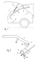
- a motor vehicle in the form of a passenger car, according to FIG. 1, has a loading area 1 in a rear area, which is accessible on the rear side via a rear cutout 2 in a vehicle body.
- the rear cutout 2 is closed by a tailgate 3, which is mounted to pivot about a hinge axis 5, which is aligned in the vehicle transverse direction, in a roof frame portion of the vehicle body.
- An opening movement of the tailgate 3 is supported by a gas spring arrangement 4.
- the tailgate 3 is mounted pivotably about the hinge axis 5 by means of tailgate-side hinge parts 6 of a hinge arrangement.
- the loading space 1 can be covered by a load compartment cover 7 to 9.
- the luggage compartment cover 7 to 9 comprises a winding shaft 7, which is preferably rotatably mounted in a cassette housing on the vehicle side.
- a flexible sheet 8 is held up and unwound, wherein the winding shaft 7 in the take-up by a clock spring, not shown, is permanently torque-applied.
- a front end in the extension direction of the flexible sheet 8 is connected to a pull-9, which extends over the entire width of the sheet 8 and with laterally beyond the side edges of the sheet 8 protruding end portions in vehicle-mounted guides 10 parallel to the winding axis of the winding shaft 7 is displaceable ,
- the vehicle-side guides 10 are provided on opposite side regions of the loading space 1 and extend in the illustrated embodiment in each case along a D-pillar of the vehicle body approximately from a transom edge to the roof area of the vehicle interior. The transom edge roughly corresponds to a vehicle belt line.
- the extension profile 9 is displaceable between a comfort position shown in FIG.
- each vehicle-side guide 10 is provided with a mechanical guide means 11, which in the illustrated embodiment as a flexible rack or as a flexible shaft a toothed or thread-shaped outer profiling is formed.
- the pull-9 is with its opposite end portions in not shown in particular releasably held, which are fixedly connected to the respective guide means 11. The extension profile 9 can thus be posted as needed from the carriers.
- the guide means 11 is associated with a drive unit 13 to 16 shown in FIG. 2, which is realized by a gear transmission.
- the guide means 11 is flanked on both sides by a respective drive wheel 14, 15 which can transmit linear forces to the guide means 11 in different directions.
- the one drive wheel 15 is driven by a spring motor 16.
- the other drive wheel 14 is connected via a cable or belt train 12, 13 with the tailgate 3 in operative connection.
- the rope or belt train comprises a winding drum 13 whose winding diameter is less than a pitch diameter of the gear wheel 14 designed as a gear wheel, so that depending on the design of the different diameters of the winding drum 13 and the drive wheel 14, a desired transmission ratio can be achieved.
- the spring motor 16 of the drive wheel 15 causes a torque on the drive wheel in the opposite direction of rotation to the torque that results from the tensile load of the rope or belt train on the other drive wheel 14.
- a tailgate-side hinge part 6a of the tailgate 3 forms an eccentric to the hinge axis 5 spirally curved, dimensionally stable hinge arm, which serves as a deflection means in the context of the invention.
- an outer curvature of the hinge arm 6a on a guide profiling which causes a centering of the cable section 12 in a wrap of the outer curvature of the hinge arm 6a.
- slipping of the cable section 12 is avoided by the hinge arm 6a.
- FIG. 2 is clearly visible that in the open Position of the tailgate 3, the cable section 12 is in its streamlined, straight and parallel to the guide means 11 extending extension. In this position, the pull-9 is shifted to an upper comfort position.
- the rigid arranged on the tailgate 3 hinge arm 6a deflects the cable section 12 and thereby inevitably leads to an increase in the required cable length, which in turn to a deducting a further cable area of the Winding drum 13 leads.
- the cable section 12 is attached to the hinge arm 6a at a suitable location. The deflection of the cable section 12 thus leads to a rotational movement of the winding drum 13 and thus in this drive direction also to a rotational movement of the drive wheel 14, so that the guide means 11 is moved obliquely downward in the direction of the arrow. As a result, the pull-9 is inevitably moved down.
- the dimensions of the displacement path of the guide means 11 and the pivoting path of the tailgate 3 are designed so that the extension profile 9 and the fabric 8 are in the closed position of the tailgate 3 in its horizontal operating position.
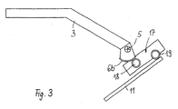
- the positive coupling between the tailgate 3 and guide means 11 for the extension profile 9 is not achieved by a cable, but rather by a transmission gear in the region of the hinge axis 5.
- a curved toothing 6b is provided, which is arranged coaxially and concentrically to the hinge axis 5 and is fixedly connected to the tailgate 3.
- the curved teeth 6b meshes with a drive pinion 18 of a transmission gear 17, the end-side output pinion 19 meshes with the guide means 11, preferably in the form of a flexible rack.
- the transmission gear 17 a transmission gear is integrated in a manner not shown, in order to achieve an adaptation and coordination between pivoting the tailgate 3 and displacement path of the guide means 11 analogous to the embodiment described above.
- the transmission gear 17 including the transmission gear is designed as a multi-stage gear transmission, which is housed in a separate housing unit, which in turn can be mounted and accommodated on the vehicle side in the hinge assembly.
Landscapes
- Engineering & Computer Science (AREA)
- Mechanical Engineering (AREA)
- Body Structure For Vehicles (AREA)
- Massaging Devices (AREA)
- Paper (AREA)
- Control Of Motors That Do Not Use Commutators (AREA)
- Pivots And Pivotal Connections (AREA)
- Hinges (AREA)
Abstract
Erfindungsgemäß sind die Bewegungsübertragungsmittel (6a,6b) im Bereich einer Scharnieranordnung des Karosserieteils angeordnet.
Einsatz bei Personenkraftwagen.
Description
- Die Erfindung betrifft eine Zwangskopplungseinrichtung zwischen einem um eine Scharnierachse an einer Fahrzeugkarosserie angelenkten, beweglichen Karosserieteil und wenigstens einem Führungsmittel zur Verlagerung einer Laderaumabdeckung zwischen zwei unterschiedlichen Funktionsstellungen, wobei die Zwangskopplungseinrichtung mechanische Bewegungsübertragungsmittel aufweist, die mit dem Karosserieteil einerseits und dem Führungsmittel andererseits in Wirkverbindung stehen.
- Aus der WO 98/24657 A2 ist eine Zwangskopplungseinrichtung zwischen einer Heckklappe eines Kraftfahrzeugs und Führungsmitteln zur Verlagerung einer Laderaumabdeckung zwischen einer horizontalen Funktionsstellung und einer nach oben verlagerten Komfortstellung bekannt. Die Zwangskopplungseinrichtung umfasst Bewegungsübertragungsmittel in Form von drucksteifen Hebelstangen, die innenseitig an der Heckklappe einerseits und an den fahrzeugseitigen Führungen für ein Auszugsprofil der Laderaumabdeckung andererseits angelenkt sind. Die Hebelstangen können beim Öffnen und Schließen der Heckklappe ein Verletzungs- oder Beschädigungspotential darstellen.
- Aufgabe der Erfindung ist es, eine Zwangskopplungseinrichtung der eingangs genannten Art zu schaffen, die ein Gefährdungs- oder Beschädigungspotential bei einer Karosserieteilbewegung und einer zwangsgekoppelten Verlagerung der Laderaumabdeckung vermeidet oder zumindest wesentlich reduziert.
- Diese Aufgabe wird dadurch gelöst, dass die Bewegungsübertragungsmittel im Bereich einer Scharnieranordnung des Karosserieteils angeordnet sind. Die Scharnieranordnung für das Karosserieteil befindet sich in einem Rand- oder Rahmenbereich eines Karosserieausschnittes, den das Karosserieteil verdecken soll. Falls das Karosserieteil als Heckklappe für einen Personenkraftwagen ausgeführt ist, befindet sich die Scharnieranordnung in einem Dachrahmenbereich und ist zumindest teilweise hinter Innenraumverkleidungen verdeckt. Im Bereich der Scharnieranordnung angeordnet bedeutet eine unmittelbare Zuordnung des wenigstens einen Bewegungsübertragungsmittels zu wenigstens einem Scharnierteil der Scharnieranordnung. Vorzugsweise erfolgt eine Zuordnung des Bewegungsübertragungsmittels zu einem heckklappenseitigen Teil der Scharnieranordnung, das die Heckklappenbewegung mitmacht.
- In Ausgestaltung der Erfindung umfassen die Bewegungsübertragungsmittel ein Übersetzungsgetriebe, um einen Schwenkweg des Karosserieteiles auf einen Verlagerungsweg der Führungsmittel abzustimmen. Diese Ausgestaltung ist vorteilhaft, da aufgrund der Anordnung der Bewegungsübertragungsmittel im Bereich der Scharnieranordnung der Schwenkweg aufgrund der Nähe zur Scharnierachse vergleichsweise gering ist. Das Übersetzungsgetriebe übersetzt den relativ geringen Schwenkweg in den größeren Verlagerungsweg für die Laderaumabdeckung. Vorzugsweise ist der Verlagerungsweg der Laderaumabdeckung durch eine obere Endposition und eine untere Endposition begrenzt, wobei die obere Endposition eine nach oben verlagerte Komfortstellung der Laderaumabdeckung und die untere Endposition eine etwa horizontal ausgerichtete Funktionsstellung der Laderaumabdeckung bildet.
- In weiterer Ausgestaltung der Erfindung umfassen die Bewegungsübertragungsmittel eine Zugmittelanordnung, die mit den Führungsmitteln in Wirkverbindung steht, und die Scharnieranordnung umfasst ein exzentrisch zu der Scharnierachse angeordnetes und mit dem Karosserieteil festes Umlenkmittel, das einen Zugmittelabschnitt der Zugmittelanordnung bei einer Bewegung des Karosserieteiles auslenkt. Die Umlenkung des Zugmittelabschnittes führt zu einer Zugbelastung auf die Zugmittelanordnung, die in eine Drehbewegung eines Antriebsritzels umgesetzt werden kann, das eine Übertragung in eine Längsverlagerung des Führungsmittels ermöglicht. Als Zugmittelanordnung ist insbesondere ein Seil- oder Riemenzug vorgesehen.
- In weiterer Ausgestaltung der Erfindung ist der Scharnieranordnung eine koaxial zur Scharnierachse angeordnete Bogenverzahnung zugeordnet, die fest mit dem Karosserieteil verbunden ist, und die mit einem Antriebsritzel eines mit dem Führungsmittel in Wirkverbindung stehenden Übertragungsgetriebes kämmt. Die Bogenverzahnung weist vorzugsweise eine Kreisbogenform auf und ist konzentrisch zur Scharnierachse ausgerichtet. Das Übertragungsgetriebe stellt ein Zahnradgetriebe dar, dessen abtriebseitiges Zahnrad insbesondere auf eine flexible Zahnstange wirkt, die Teil der Führungsmittel zur Verlagerung der Laderaumabdeckung ist.
- In weiterer Ausgestaltung der Erfindung sind das Übertragungsgetriebe und das Übersetzungsgetriebe miteinander kombiniert. Die Kombination wird vorzugsweise durch ein mehrstufiges Zahnradgetriebe gebildet.
- Weitere Vorteile und Merkmale der Erfindung ergeben sich aus den Ansprüchen sowie aus der nachfolgenden Beschreibung bevorzugter Ausführungsbeispiele der Erfindung, die anhand der Zeichnungen dargestellt sind.
- Fig. 1
- zeigt schematisch einen Heckbereich eines mit einer Heckklappe versehenen Kraftfahrzeugs, dessen Laderaum mit einer zwischen zwei unterschiedlichen Funktionsstellungen verlagerbaren Laderaumabdeckung versehen ist,
- Fig. 2
- in vergrößerter, schematisierter Darstellung eine Ausführungsform einer erfindungsgemäßen Zwangskopplungseinrichtung für das Kraftfahrzeug nach Fig. 1 und
- Fig. 3
- eine weitere Ausführungsform einer erfindungsgemäßen Zwangskopplungseinrichtung für das Kraftfahrzeug nach Fig. 1.
- Ein Kraftfahrzeug in Form eines Personenkraftwagens weist gemäß Fig. 1 in einem Heckbereich einen Laderaum 1 auf, der heckseitig über einen Heckausschnitt 2 in einer Fahrzeugkarosserie zugänglich ist. Der Heckausschnitt 2 ist durch eine Heckklappe 3 verschließbar, die um eine Scharnierachse 5, die in Fahrzeugquerrichtung ausgerichtet ist, in einem Dachrahmenbereich der Fahrzeugkarosserie schwenkbeweglich gelagert ist. Eine Öffnungsbewegung der Heckklappe 3 wird durch eine Gasdruckfederanordnung 4 unterstützt. Die Heckklappe 3 ist mittels heckklappenseitiger Scharnierteile 6 einer Scharnieranordnung um die Scharnierachse 5 schwenkbeweglich gelagert.
- Der Laderaum 1 ist durch eine Laderaumabdeckung 7 bis 9 abdeckbar. Die Laderaumabdeckung 7 bis 9 umfasst eine Wickelwelle 7, die vorzugsweise in einem Kassettengehäuse fahrzeugseitig drehbar gelagert ist. Auf der Wickelwelle 7 ist ein flexibles Flächengebilde 8 auf- und abwickelbar gehalten, wobei die Wickelwelle 7 in Aufwickelrichtung durch eine nicht dargestellte Wickelfeder permanent drehmomentbeaufschlagt ist. Ein in Auszugrichtung vorderes Stirnende des flexiblen Flächengebildes 8 ist mit einem Auszugsprofil 9 verbunden, das sich über die gesamte Breite des Flächengebildes 8 erstreckt und mit seitlich über die Seitenränder des Flächengebildes 8 hinausragenden Stirnbereichen in fahrzeugseitigen Führungen 10 parallel zur Wickelachse der Wickelwelle 7 verlagerbar gehalten ist. Die fahrzeugseitigen Führungen 10 sind an gegenüberliegenden Seitenbereichen des Laderaumes 1 vorgesehen und erstrecken sich bei der dargestellten Ausführungsform jeweils längs einer D-Säule der Fahrzeugkarosserie etwa von einer Heckspiegelkante bis in den Dachbereich des Fahrzeuginnenraumes. Die Heckspiegelkante entspricht in etwa einer Fahrzeuggürtellinie. Das Auszugsprofil 9 ist zwischen einer in Fig. 1 mit durchgezogener Linie dargestellten Komfortstellung, die die obere Endposition des Flächengebildes 8 darstellt, und einer unteren Endposition, die die horizontale Auszugsstellung des Flächengebildes 8 bildet, längs der fahrzeugseitigen Führungen 10 verlagerbar. Die beiden einander gegenüberliegenden fahrzeugseitigen Führungen 10 sind exakt parallel zueinander geführt, so dass eine gleichmäßige Parallelverlagerung des Auszugsprofils 9 relativ zur Wickelachse der Wickelwelle 7 ermöglicht ist. Dies bewirkt eine gleichmäßige Auszugs- oder Einzugsbewegung des Flächengebildes 8. Um die Verlagerung des Auszugsprofils 9 in den fahrzeugseitigen Führungen 10 zu ermöglichen, ist jede fahrzeugseitige Führung 10 mit einem mechanischen Führungsmittel 11 versehen, das im dargestellten Ausführungsbeispiel als flexible Zahnstange oder als flexible Welle mit einer verzahnungs- oder gewindeförmigen Außenprofilierung ausgebildet ist. Das Auszugsprofil 9 ist mit seinen gegenüberliegenden Stirnbereichen in nicht näher dargestellten Mitnehmern insbesondere lösbar gehalten, die fest mit dem jeweiligen Führungsmittel 11 verbunden sind. Das Auszugsprofil 9 kann somit bei Bedarf aus den Mitnehmern ausgehängt werden.
- Um eine Zwangskopplung einer Verlagerungsbewegung des Auszugsprofils 9 mit einer Öffnungs- oder Schließbewegung der Heckklappe 3 zu bewirken, ist gemäß Fig. 2 dem Führungsmittel 11 eine Antriebseinheit 13 bis 16 zugeordnet, die durch ein Zahnradgetriebe verwirklicht ist. Das Führungsmittel 11 wird beidseitig flankiert von jeweils einem Antriebsrad 14, 15, die in unterschiedlichen Richtungen Linearkräfte auf das Führungsmittel 11 übertragen können. Das eine Antriebsrad 15 ist durch einen Federmotor 16 angetrieben. Das andere Antriebsrad 14 steht über einen Seil- oder Riemenzug 12, 13 mit der Heckklappe 3 in Wirkverbindung. Der Seil- oder Riemenzug umfasst eine Wickeltrommel 13, deren Wickeldurchmesser geringer ist als ein Teilkreisdurchmesser des als Zahnrad ausgeführten Antriebsrades 14, so dass je nach Gestaltung der unterschiedlichen Durchmesser der Wickeltrommel 13 und des Antriebsrades 14 ein gewünschtes Übersetzungsverhältnis erzielbar ist. Der Federmotor 16 des Antriebsrades 15 bewirkt ein Drehmoment auf das Antriebsrad in entgegengesetzter Drehrichtung zu dem Drehmoment, das durch die Zugbelastung des Seil- oder Riemenzuges auf das andere Antriebsrad 14 entsteht.
- Ein heckklappenseitiger Scharnierteil 6a der Heckklappe 3 bildet einen exzentrisch zur Scharnierachse 5 spiralartig gekrümmten, formstabilen Scharnierarm, der als Umlenkmittel im Sinne der Erfindung dient. Hierzu weist eine Außenkrümmung des Scharnierarmes 6a eine Führungsprofilierung auf, die eine Zentrierung des Seilabschnittes 12 bei einer Umschlingung der Außenkrümmung des Scharnierarmes 6a bewirkt. Hierdurch wird ein Abrutschen des Seilabschnittes 12 von dem Scharnierarm 6a vermieden. Anhand der Fig. 2 ist gut erkennbar, dass in der geöffneten Stellung der Heckklappe 3 sich der Seilabschnitt 12 in seiner gestrafften, geradlinig und parallel zum Führungsmittel 11 verlaufenden Streckung befindet. In dieser Position ist das Auszugsprofil 9 in eine obere Komfortstellung verlagert. Sobald nun die Heckklappe 3 in Richtung des Pfeiles in ihre Schließstellung überführt wird, lenkt der starr an der Heckklappe 3 angeordnete Scharnierarm 6a den Seilabschnitt 12 aus und führt dadurch zwangsläufig zu einer Vergrößerung der benötigten Seillänge, was wiederum zu einem Abziehen eines weiteren Seilbereiches von der Wickeltrommel 13 führt. Selbstverständlich ist der Seilabschnitt 12 an dem Scharnierarm 6a an geeigneter Stelle befestigt. Die Umlenkung des Seilabschnittes 12 führt somit zu einer Drehbewegung der Wickeltrommel 13 und damit in dieser Antriebsrichtung auch zu einer Drehbewegung des Antriebsrades 14, so dass das Führungsmittel 11 in Richtung des Pfeiles schräg nach unten bewegt wird. Dadurch wird zwangsläufig auch das Auszugsprofil 9 nach unten bewegt. Vorzugsweise sind die Dimensionierungen des Verlagerungsweges des Führungsmittels 11 und des Schwenkweges der Heckklappe 3 so gestaltet, dass das Auszugsprofil 9 und das Flächengebilde 8 sich in der geschlossenen Position der Heckklappe 3 in ihrer horizontalen Funktionsstellung befinden.
- Bei einem erneuten Öffnen der Heckklappe 3 erfolgt in entsprechend umgekehrter Reihenfolge eine allmähliche Streckung des Seilabschnittes 12, wobei die überschießende Seillänge durch eine Rückholfeder der Wickeltrommel 13 auf diese aufgewickelt wird. Die Verlagerungsbewegung des Führungsmittels und des Auszugsprofils 9 nach oben wird durch das gegenüberliegende Antriebsrad 15 bewirkt, dessen Federmotor 16 bei der Bewegung des Führungsmittels 11 nach unten gespannt wurde und der nun eine Rückbewegung des Führungsmittels 11 nach oben bewirkt.
- Bei der Ausführungsform gemäß Fig. 3 wird die Zwangskopplung zwischen Heckklappe 3 und Führungsmittel 11 für das Auszugsprofil 9 nicht durch einen Seilzug, sondern vielmehr durch ein Übertragungsgetriebe im Bereich der Scharnierachse 5 erzielt. Hierzu ist heckklappenseitig eine Bogenverzahnung 6b vorgesehen, die koaxial und konzentrisch zu der Scharnierachse 5 angeordnet ist und fest mit der Heckklappe 3 verbunden ist. Die Bogenverzahnung 6b kämmt mit einem Antriebsritzel 18 eines Übertragungsgetriebes 17, dessen endseitiges Abtriebsritzel 19 mit dem Führungsmittel 11, vorzugsweise in Form einer flexiblen Zahnstange, kämmt. In dem Übertragungsgetriebe 17 ist in nicht dargestellter Weise ein Übersetzungsgetriebe integriert, um analog zu der zuvor beschriebenen Ausführungsform eine Anpassung und Abstimmung zwischen Schwenkweg der Heckklappe 3 und Verlagerungsweg des Führungsmittels 11 zu erzielen. Vorzugsweise ist das Übertragungsgetriebe 17 einschließlich des Übersetzungsgetriebes als mehrstufiges Zahnradgetriebe ausgeführt, das in einer eigenen Gehäuseeinheit untergebracht ist, die wiederum fahrzeugseitig im Bereich der Scharnieranordnung befestigt und untergebracht werden kann.
Claims (5)
- Zwangskopplungseinrichtung zwischen einem um eine Scharnierachse an einer Fahrzeugkarosserie angelenkten beweglichen Karosserieteil und wenigstens einem Führungsmittel zur Verlagerung einer Laderaumabdeckung zwischen zwei unterschiedlichen Funktionsstellungen, wobei die Zwangskopplungseinrichtung mechanische Bewegungsübertragungsmittel aufweist, die mit dem Karosserieteil einerseits und dem Führungsmittel andererseits in Wirkverbindung stehen, dadurch gekennzeichnet, dass die Bewegungsübertragungsmittel (6a, 6b) im Bereich einer Scharnieranordnung des Karosserieteils (3) angeordnet sind.
- Zwangskopplungseinrichtung nach Anspruch 1, dadurch gekennzeichnet, dass die Bewegungsübertragungsmittel ein Übersetzungsgetriebe (17) umfassen, um einen Schwenkweg des Karosserieteils (3) auf einen Verlagerungsweg der Führungsmittel (11) abzustimmen.
- Zwangskopplungseinrichtung nach Anspruch 1 oder 2, dadurch gekennzeichnet, dass die Bewegungsübertragungsmittel eine Zugmittelanordnung (12 bis 14) umfassen, die mit den Führungsmitteln (11) in Wirkverbindung steht, und dass die Scharnieranordnung ein exzentrisch zu der Scharnierachse (5) angeordnetes und mit dem Karosserieteil (3) festes Umlenkmittel (6a) umfasst, das einen Zugmittelabschnitt (12) der Zugmittelanordnung bei einer Bewegung des Karosserieteiles auslenkt.
- Zwangskopplungseinrichtung nach Anspruch 1, dadurch gekennzeichnet, dass der Scharnieranordnung eine koaxial zur Scharnierachse (5) angeordnete Bogenverzahnung (6b) zugeordnet ist, die fest mit dem Karosserieteil verbunden ist, und die mit einem Antriebsritzel (18) eines mit dem Führungsmittel in Wirkverbindung stehenden Übertragungsgetriebes (17) kämmt.
- Zwangskopplungseinrichtung nach Anspruch 4, dadurch gekennzeichnet, dass das Übertragungsgetriebe und das Übersetzungsgetriebe miteinander kombiniert sind.
Applications Claiming Priority (1)
| Application Number | Priority Date | Filing Date | Title |
|---|---|---|---|
| DE102005010762A DE102005010762A1 (de) | 2005-03-02 | 2005-03-02 | Zwangkopplungseinrichtung |
Publications (2)
| Publication Number | Publication Date |
|---|---|
| EP1698516A1 true EP1698516A1 (de) | 2006-09-06 |
| EP1698516B1 EP1698516B1 (de) | 2009-07-08 |
Family
ID=36593807
Family Applications (1)
| Application Number | Title | Priority Date | Filing Date |
|---|---|---|---|
| EP06003567A Expired - Lifetime EP1698516B1 (de) | 2005-03-02 | 2006-02-22 | Zwangskopplungseinrichtung |
Country Status (3)
| Country | Link |
|---|---|
| EP (1) | EP1698516B1 (de) |
| AT (1) | ATE435780T1 (de) |
| DE (2) | DE102005010762A1 (de) |
Cited By (2)
| Publication number | Priority date | Publication date | Assignee | Title |
|---|---|---|---|---|
| FR3051745A1 (fr) * | 2016-05-27 | 2017-12-01 | Cera Aps | Systeme de recouvrement d'un compartiment a bagages de vehicule automobile |
| CN115009375A (zh) * | 2022-06-24 | 2022-09-06 | 一汽奔腾轿车有限公司 | 一种自动变形后背门系统 |
Families Citing this family (2)
| Publication number | Priority date | Publication date | Assignee | Title |
|---|---|---|---|---|
| DE102012021851B4 (de) * | 2012-11-07 | 2015-05-21 | Audi Ag | Kraftfahrzeug umfassend eine bewegbare Heckklappe |
| DE102020207669A1 (de) | 2020-06-22 | 2021-12-23 | Bos Gmbh & Co. Kg | Tankklappenanordnung für ein Kraftfahrzeug |
Citations (3)
| Publication number | Priority date | Publication date | Assignee | Title |
|---|---|---|---|---|
| GB635187A (en) * | 1948-03-16 | 1950-04-05 | Standard Pressed Steel Co | Improvements in or relating to vehicle bodies |
| US4728141A (en) * | 1985-05-31 | 1988-03-01 | Honda Giken Kogyo Kabushiki Kaisha | Automotive rear shelf structure |
| WO1998024657A2 (de) * | 1996-12-06 | 1998-06-11 | Baumeister + Ostler Gmbh & Co. | Abdeckrollo mit vereinfachter bedienung |
-
2005
- 2005-03-02 DE DE102005010762A patent/DE102005010762A1/de not_active Withdrawn
-
2006
- 2006-02-22 EP EP06003567A patent/EP1698516B1/de not_active Expired - Lifetime
- 2006-02-22 AT AT06003567T patent/ATE435780T1/de active
- 2006-02-22 DE DE502006004155T patent/DE502006004155D1/de not_active Expired - Lifetime
Patent Citations (3)
| Publication number | Priority date | Publication date | Assignee | Title |
|---|---|---|---|---|
| GB635187A (en) * | 1948-03-16 | 1950-04-05 | Standard Pressed Steel Co | Improvements in or relating to vehicle bodies |
| US4728141A (en) * | 1985-05-31 | 1988-03-01 | Honda Giken Kogyo Kabushiki Kaisha | Automotive rear shelf structure |
| WO1998024657A2 (de) * | 1996-12-06 | 1998-06-11 | Baumeister + Ostler Gmbh & Co. | Abdeckrollo mit vereinfachter bedienung |
Cited By (2)
| Publication number | Priority date | Publication date | Assignee | Title |
|---|---|---|---|---|
| FR3051745A1 (fr) * | 2016-05-27 | 2017-12-01 | Cera Aps | Systeme de recouvrement d'un compartiment a bagages de vehicule automobile |
| CN115009375A (zh) * | 2022-06-24 | 2022-09-06 | 一汽奔腾轿车有限公司 | 一种自动变形后背门系统 |
Also Published As
| Publication number | Publication date |
|---|---|
| ATE435780T1 (de) | 2009-07-15 |
| EP1698516B1 (de) | 2009-07-08 |
| DE502006004155D1 (de) | 2009-08-20 |
| DE102005010762A1 (de) | 2006-09-14 |
Similar Documents
| Publication | Publication Date | Title |
|---|---|---|
| EP1123824B1 (de) | Seitenfensterrollo | |
| EP1123825B9 (de) | Heckfensterrollo | |
| EP2212157B1 (de) | Anzeigeeinrichtung in einem kraftfahrzeug | |
| EP1306251B1 (de) | Geteiltes Fensterrollo für Kraftfahrzeuge | |
| DE3500874A1 (de) | Ausstellvorrichtung fuer um eine achse verschwenkbare scheiben, hubdaecher o.dgl., insbesondere von kraftfahrzeugen | |
| DE102022114095B3 (de) | Lenksäule mit hohler Teleskopwelle | |
| EP1636455A1 (de) | Scharniervorrichtung | |
| EP1771311A1 (de) | Rollosystem | |
| EP3266631B1 (de) | Beschattungsvorrichtung für eine scheibe eines kraftfahrzeugs | |
| DE102011052026A1 (de) | Cabriolet mit einem Verdeck und einer Windschotteinrichtung | |
| EP3478521B1 (de) | Beschattungsvorrichtung für eine scheibe eines kraftfahrzeugs | |
| DE2204623B2 (de) | Mechanisch betätigbares Dreipunkt-Sicherheitsgurtsystem für Kraftfahrzeuge | |
| EP3090901A1 (de) | Schutzvorrichtung für einen fahrzeuginnenraum | |
| EP1698516B1 (de) | Zwangskopplungseinrichtung | |
| DE202020106072U1 (de) | Türantrieb für Fahrzeugschiebetürsystem | |
| EP1811107A2 (de) | Antreibseinheit für ein Kraftfahrzeugtürschloss | |
| EP1870271B1 (de) | Fensterrollo für ein Fahrzeugfenster | |
| DE202007005160U1 (de) | Fahrzeugrollo | |
| DE202006003901U1 (de) | Schiebetüranordnung für ein Kraftfahrzeug | |
| DE3345961C2 (de) | ||
| DE102017006125B4 (de) | Schwenkvorrichtung für eine Zugangsklappe eines Kraftfahrzeugs und Kraftfahrzeug | |
| EP1674312B1 (de) | Seitenfensterrollo für Kraftfahrzeuge | |
| DE202007008178U1 (de) | Seitenfensterrollo | |
| EP1698517B1 (de) | Laderaumabdeckung für ein Kraftfahrzeug | |
| EP1849635A1 (de) | Fensterrollo, welches an der Innenseite eines Kraftfahrzeugfensters anzuordnen ist |
Legal Events
| Date | Code | Title | Description |
|---|---|---|---|
| PUAI | Public reference made under article 153(3) epc to a published international application that has entered the european phase |
Free format text: ORIGINAL CODE: 0009012 |
|
| AK | Designated contracting states |
Kind code of ref document: A1 Designated state(s): AT BE BG CH CY CZ DE DK EE ES FI FR GB GR HU IE IS IT LI LT LU LV MC NL PL PT RO SE SI SK TR |
|
| AX | Request for extension of the european patent |
Extension state: AL BA HR MK YU |
|
| 17P | Request for examination filed |
Effective date: 20070109 |
|
| 17Q | First examination report despatched |
Effective date: 20070208 |
|
| AKX | Designation fees paid |
Designated state(s): AT BE BG CH CY CZ DE DK EE ES FI FR GB GR HU IE IS IT LI LT LU LV MC NL PL PT RO SE SI SK TR |
|
| GRAP | Despatch of communication of intention to grant a patent |
Free format text: ORIGINAL CODE: EPIDOSNIGR1 |
|
| GRAJ | Information related to disapproval of communication of intention to grant by the applicant or resumption of examination proceedings by the epo deleted |
Free format text: ORIGINAL CODE: EPIDOSDIGR1 |
|
| GRAP | Despatch of communication of intention to grant a patent |
Free format text: ORIGINAL CODE: EPIDOSNIGR1 |
|
| GRAS | Grant fee paid |
Free format text: ORIGINAL CODE: EPIDOSNIGR3 |
|
| GRAA | (expected) grant |
Free format text: ORIGINAL CODE: 0009210 |
|
| AK | Designated contracting states |
Kind code of ref document: B1 Designated state(s): AT BE BG CH CY CZ DE DK EE ES FI FR GB GR HU IE IS IT LI LT LU LV MC NL PL PT RO SE SI SK TR |
|
| REG | Reference to a national code |
Ref country code: GB Ref legal event code: FG4D Free format text: NOT ENGLISH |
|
| REG | Reference to a national code |
Ref country code: CH Ref legal event code: EP |
|
| REG | Reference to a national code |
Ref country code: IE Ref legal event code: FG4D |
|
| REF | Corresponds to: |
Ref document number: 502006004155 Country of ref document: DE Date of ref document: 20090820 Kind code of ref document: P |
|
| PG25 | Lapsed in a contracting state [announced via postgrant information from national office to epo] |
Ref country code: SI Free format text: LAPSE BECAUSE OF FAILURE TO SUBMIT A TRANSLATION OF THE DESCRIPTION OR TO PAY THE FEE WITHIN THE PRESCRIBED TIME-LIMIT Effective date: 20090708 |
|
| NLV1 | Nl: lapsed or annulled due to failure to fulfill the requirements of art. 29p and 29m of the patents act | ||
| PG25 | Lapsed in a contracting state [announced via postgrant information from national office to epo] |
Ref country code: ES Free format text: LAPSE BECAUSE OF FAILURE TO SUBMIT A TRANSLATION OF THE DESCRIPTION OR TO PAY THE FEE WITHIN THE PRESCRIBED TIME-LIMIT Effective date: 20091019 Ref country code: IS Free format text: LAPSE BECAUSE OF FAILURE TO SUBMIT A TRANSLATION OF THE DESCRIPTION OR TO PAY THE FEE WITHIN THE PRESCRIBED TIME-LIMIT Effective date: 20091108 Ref country code: LT Free format text: LAPSE BECAUSE OF FAILURE TO SUBMIT A TRANSLATION OF THE DESCRIPTION OR TO PAY THE FEE WITHIN THE PRESCRIBED TIME-LIMIT Effective date: 20090708 Ref country code: FI Free format text: LAPSE BECAUSE OF FAILURE TO SUBMIT A TRANSLATION OF THE DESCRIPTION OR TO PAY THE FEE WITHIN THE PRESCRIBED TIME-LIMIT Effective date: 20090708 |
|
| REG | Reference to a national code |
Ref country code: IE Ref legal event code: FD4D |
|
| PG25 | Lapsed in a contracting state [announced via postgrant information from national office to epo] |
Ref country code: NL Free format text: LAPSE BECAUSE OF FAILURE TO SUBMIT A TRANSLATION OF THE DESCRIPTION OR TO PAY THE FEE WITHIN THE PRESCRIBED TIME-LIMIT Effective date: 20090708 Ref country code: PL Free format text: LAPSE BECAUSE OF FAILURE TO SUBMIT A TRANSLATION OF THE DESCRIPTION OR TO PAY THE FEE WITHIN THE PRESCRIBED TIME-LIMIT Effective date: 20090708 Ref country code: LV Free format text: LAPSE BECAUSE OF FAILURE TO SUBMIT A TRANSLATION OF THE DESCRIPTION OR TO PAY THE FEE WITHIN THE PRESCRIBED TIME-LIMIT Effective date: 20090708 |
|
| PG25 | Lapsed in a contracting state [announced via postgrant information from national office to epo] |
Ref country code: PT Free format text: LAPSE BECAUSE OF FAILURE TO SUBMIT A TRANSLATION OF THE DESCRIPTION OR TO PAY THE FEE WITHIN THE PRESCRIBED TIME-LIMIT Effective date: 20091109 Ref country code: BG Free format text: LAPSE BECAUSE OF FAILURE TO SUBMIT A TRANSLATION OF THE DESCRIPTION OR TO PAY THE FEE WITHIN THE PRESCRIBED TIME-LIMIT Effective date: 20091008 |
|
| PG25 | Lapsed in a contracting state [announced via postgrant information from national office to epo] |
Ref country code: CZ Free format text: LAPSE BECAUSE OF FAILURE TO SUBMIT A TRANSLATION OF THE DESCRIPTION OR TO PAY THE FEE WITHIN THE PRESCRIBED TIME-LIMIT Effective date: 20090708 Ref country code: DK Free format text: LAPSE BECAUSE OF FAILURE TO SUBMIT A TRANSLATION OF THE DESCRIPTION OR TO PAY THE FEE WITHIN THE PRESCRIBED TIME-LIMIT Effective date: 20090708 Ref country code: IE Free format text: LAPSE BECAUSE OF FAILURE TO SUBMIT A TRANSLATION OF THE DESCRIPTION OR TO PAY THE FEE WITHIN THE PRESCRIBED TIME-LIMIT Effective date: 20090708 Ref country code: RO Free format text: LAPSE BECAUSE OF FAILURE TO SUBMIT A TRANSLATION OF THE DESCRIPTION OR TO PAY THE FEE WITHIN THE PRESCRIBED TIME-LIMIT Effective date: 20090708 Ref country code: EE Free format text: LAPSE BECAUSE OF FAILURE TO SUBMIT A TRANSLATION OF THE DESCRIPTION OR TO PAY THE FEE WITHIN THE PRESCRIBED TIME-LIMIT Effective date: 20090708 |
|
| PLBE | No opposition filed within time limit |
Free format text: ORIGINAL CODE: 0009261 |
|
| STAA | Information on the status of an ep patent application or granted ep patent |
Free format text: STATUS: NO OPPOSITION FILED WITHIN TIME LIMIT |
|
| PG25 | Lapsed in a contracting state [announced via postgrant information from national office to epo] |
Ref country code: SK Free format text: LAPSE BECAUSE OF FAILURE TO SUBMIT A TRANSLATION OF THE DESCRIPTION OR TO PAY THE FEE WITHIN THE PRESCRIBED TIME-LIMIT Effective date: 20090708 |
|
| 26N | No opposition filed |
Effective date: 20100409 |
|
| BERE | Be: lapsed |
Owner name: BOS G.M.B.H. & CO. KG Effective date: 20100228 |
|
| REG | Reference to a national code |
Ref country code: CH Ref legal event code: PL |
|
| GBPC | Gb: european patent ceased through non-payment of renewal fee |
Effective date: 20100222 |
|
| PG25 | Lapsed in a contracting state [announced via postgrant information from national office to epo] |
Ref country code: LI Free format text: LAPSE BECAUSE OF NON-PAYMENT OF DUE FEES Effective date: 20100228 Ref country code: MC Free format text: LAPSE BECAUSE OF NON-PAYMENT OF DUE FEES Effective date: 20100301 Ref country code: GR Free format text: LAPSE BECAUSE OF FAILURE TO SUBMIT A TRANSLATION OF THE DESCRIPTION OR TO PAY THE FEE WITHIN THE PRESCRIBED TIME-LIMIT Effective date: 20091009 Ref country code: CH Free format text: LAPSE BECAUSE OF NON-PAYMENT OF DUE FEES Effective date: 20100228 |
|
| REG | Reference to a national code |
Ref country code: FR Ref legal event code: ST Effective date: 20101029 |
|
| PG25 | Lapsed in a contracting state [announced via postgrant information from national office to epo] |
Ref country code: FR Free format text: LAPSE BECAUSE OF NON-PAYMENT OF DUE FEES Effective date: 20100301 |
|
| PG25 | Lapsed in a contracting state [announced via postgrant information from national office to epo] |
Ref country code: BE Free format text: LAPSE BECAUSE OF NON-PAYMENT OF DUE FEES Effective date: 20100228 |
|
| PG25 | Lapsed in a contracting state [announced via postgrant information from national office to epo] |
Ref country code: IT Free format text: LAPSE BECAUSE OF FAILURE TO SUBMIT A TRANSLATION OF THE DESCRIPTION OR TO PAY THE FEE WITHIN THE PRESCRIBED TIME-LIMIT Effective date: 20090708 Ref country code: GB Free format text: LAPSE BECAUSE OF NON-PAYMENT OF DUE FEES Effective date: 20100222 |
|
| PG25 | Lapsed in a contracting state [announced via postgrant information from national office to epo] |
Ref country code: CY Free format text: LAPSE BECAUSE OF FAILURE TO SUBMIT A TRANSLATION OF THE DESCRIPTION OR TO PAY THE FEE WITHIN THE PRESCRIBED TIME-LIMIT Effective date: 20090708 |
|
| PG25 | Lapsed in a contracting state [announced via postgrant information from national office to epo] |
Ref country code: SE Free format text: LAPSE BECAUSE OF FAILURE TO SUBMIT A TRANSLATION OF THE DESCRIPTION OR TO PAY THE FEE WITHIN THE PRESCRIBED TIME-LIMIT Effective date: 20090708 Ref country code: LU Free format text: LAPSE BECAUSE OF NON-PAYMENT OF DUE FEES Effective date: 20100222 Ref country code: HU Free format text: LAPSE BECAUSE OF FAILURE TO SUBMIT A TRANSLATION OF THE DESCRIPTION OR TO PAY THE FEE WITHIN THE PRESCRIBED TIME-LIMIT Effective date: 20100109 |
|
| PG25 | Lapsed in a contracting state [announced via postgrant information from national office to epo] |
Ref country code: TR Free format text: LAPSE BECAUSE OF FAILURE TO SUBMIT A TRANSLATION OF THE DESCRIPTION OR TO PAY THE FEE WITHIN THE PRESCRIBED TIME-LIMIT Effective date: 20090708 |
|
| REG | Reference to a national code |
Ref country code: AT Ref legal event code: MM01 Ref document number: 435780 Country of ref document: AT Kind code of ref document: T Effective date: 20110222 |
|
| PG25 | Lapsed in a contracting state [announced via postgrant information from national office to epo] |
Ref country code: AT Free format text: LAPSE BECAUSE OF NON-PAYMENT OF DUE FEES Effective date: 20110222 |
|
| PGFP | Annual fee paid to national office [announced via postgrant information from national office to epo] |
Ref country code: DE Payment date: 20150227 Year of fee payment: 10 |
|
| REG | Reference to a national code |
Ref country code: DE Ref legal event code: R119 Ref document number: 502006004155 Country of ref document: DE |
|
| PG25 | Lapsed in a contracting state [announced via postgrant information from national office to epo] |
Ref country code: DE Free format text: LAPSE BECAUSE OF NON-PAYMENT OF DUE FEES Effective date: 20160901 |