EP1693442A1 - Aerosolabscheider in einer Anlage zur Rückgewinnung von Kohlendioxid - Google Patents
Aerosolabscheider in einer Anlage zur Rückgewinnung von Kohlendioxid Download PDFInfo
- Publication number
- EP1693442A1 EP1693442A1 EP05003306A EP05003306A EP1693442A1 EP 1693442 A1 EP1693442 A1 EP 1693442A1 EP 05003306 A EP05003306 A EP 05003306A EP 05003306 A EP05003306 A EP 05003306A EP 1693442 A1 EP1693442 A1 EP 1693442A1
- Authority
- EP
- European Patent Office
- Prior art keywords
- aerosol
- gas
- separator
- compressor
- recovery
- Prior art date
- Legal status (The legal status is an assumption and is not a legal conclusion. Google has not performed a legal analysis and makes no representation as to the accuracy of the status listed.)
- Granted
Links
- 239000000443 aerosol Substances 0.000 title claims abstract description 52
- CURLTUGMZLYLDI-UHFFFAOYSA-N Carbon dioxide Chemical compound O=C=O CURLTUGMZLYLDI-UHFFFAOYSA-N 0.000 title abstract 4
- 229910002092 carbon dioxide Inorganic materials 0.000 title abstract 2
- 239000001569 carbon dioxide Substances 0.000 title abstract 2
- 238000000855 fermentation Methods 0.000 claims abstract description 12
- 230000004151 fermentation Effects 0.000 claims abstract description 12
- 238000000034 method Methods 0.000 claims abstract description 11
- 238000011084 recovery Methods 0.000 claims description 23
- 238000003973 irrigation Methods 0.000 claims description 10
- 230000002262 irrigation Effects 0.000 claims description 10
- 238000000926 separation method Methods 0.000 claims description 8
- 238000011144 upstream manufacturing Methods 0.000 claims description 2
- 230000006835 compression Effects 0.000 claims 2
- 238000007906 compression Methods 0.000 claims 2
- 230000008021 deposition Effects 0.000 claims 1
- OKTJSMMVPCPJKN-UHFFFAOYSA-N Carbon Chemical compound [C] OKTJSMMVPCPJKN-UHFFFAOYSA-N 0.000 abstract 1
- 229910052799 carbon Inorganic materials 0.000 abstract 1
- 239000007789 gas Substances 0.000 description 36
- 239000004615 ingredient Substances 0.000 description 8
- XLYOFNOQVPJJNP-UHFFFAOYSA-N water Substances O XLYOFNOQVPJJNP-UHFFFAOYSA-N 0.000 description 6
- 239000012535 impurity Substances 0.000 description 5
- 238000004140 cleaning Methods 0.000 description 3
- 239000004744 fabric Substances 0.000 description 3
- 238000005457 optimization Methods 0.000 description 3
- 238000003860 storage Methods 0.000 description 3
- 239000000126 substance Substances 0.000 description 3
- 235000000346 sugar Nutrition 0.000 description 3
- 150000008163 sugars Chemical class 0.000 description 3
- 239000000470 constituent Substances 0.000 description 2
- 230000007797 corrosion Effects 0.000 description 2
- 238000005260 corrosion Methods 0.000 description 2
- 238000001035 drying Methods 0.000 description 2
- 230000000694 effects Effects 0.000 description 2
- 239000006260 foam Substances 0.000 description 2
- 239000007788 liquid Substances 0.000 description 2
- 238000012856 packing Methods 0.000 description 2
- 230000000630 rising effect Effects 0.000 description 2
- 230000004888 barrier function Effects 0.000 description 1
- 235000013405 beer Nutrition 0.000 description 1
- 238000003889 chemical engineering Methods 0.000 description 1
- 238000009792 diffusion process Methods 0.000 description 1
- 206010016256 fatigue Diseases 0.000 description 1
- 239000000945 filler Substances 0.000 description 1
- 239000003546 flue gas Substances 0.000 description 1
- 238000003197 gene knockdown Methods 0.000 description 1
- 210000004907 gland Anatomy 0.000 description 1
- 239000003365 glass fiber Substances 0.000 description 1
- 229930195733 hydrocarbon Natural products 0.000 description 1
- 150000002430 hydrocarbons Chemical class 0.000 description 1
- 230000001771 impaired effect Effects 0.000 description 1
- 238000011044 inertial separation Methods 0.000 description 1
- 230000007246 mechanism Effects 0.000 description 1
- 239000000203 mixture Substances 0.000 description 1
- 229920000728 polyester Polymers 0.000 description 1
- 238000000746 purification Methods 0.000 description 1
- 239000002904 solvent Substances 0.000 description 1
- 239000007921 spray Substances 0.000 description 1
Images

Classifications
-
- C—CHEMISTRY; METALLURGY
- C12—BIOCHEMISTRY; BEER; SPIRITS; WINE; VINEGAR; MICROBIOLOGY; ENZYMOLOGY; MUTATION OR GENETIC ENGINEERING
- C12F—RECOVERY OF BY-PRODUCTS OF FERMENTED SOLUTIONS; DENATURED ALCOHOL; PREPARATION THEREOF
- C12F3/00—Recovery of by-products
- C12F3/02—Recovery of by-products of carbon dioxide
Definitions
- the invention relates to a plant for the recovery of CO 2 and a method for recovering CO 2 resulting from the fermentation according to the preambles of claims 1 and 8.
- CO 2 recovery plants and related processes are currently used in breweries to recover the CO 2 produced during the main fermentation process, and then reuse it for other operations such as storage tank pre-pressurization and idling, carbonation, bottling, etc.
- FIG. 2 shows an example of a CO 2 recovery plant.
- the CO 2 from the fermentation vessels (not shown) is removed via appropriate CO 2 -austicianvoriquesen, and first fed to a foam 15, which serves to retain any entrained foam.
- the CO 2 gas collects in a large CO 2 gas tank a so-called CO 2 gas balloon 11, which serves as a buffer for the collection of the gas.
- the CO 2 is freed of water-soluble impurities.
- a CO 2 compressor 19 compresses the CO 2 in a known manner to a condensing pressure in a range of 15 to 22 bar.
- the liquefied CO 2 is then subjected to drying and cleaning (or vice versa), in which case the CO 2 is first fed to a dryer 16 and then to a filter 17.
- the compressed CO 2 then condenses at low temperatures and is then stored in a CO 2 storage tank 100 and can also be removed again for immediate use in the brewery.
- the present invention has for its object to provide a CO 2 recovery system provide for the recovery of produced during the fermentation of CO 2 and a corresponding method, can be prevented with the losses in the piping, equipment and machines of the recovery system.
- aerosol separator is arranged in front of the CO 2 compressor, with which the aerosol laden CO 2 gas is freed from aerosols, it is possible to prevent aerosols and these mittransportATOR ingredients in the system components of the CO 2 recovery system knock down.
- aerosols occur in particular in the application of the high-gravity process in the fermentation and the optimization of the net content of the fermenter as an ingredient in CO 2 gas. Aerosols are the finest liquid droplets with a diameter between 12 ⁇ m and approximately 0 ⁇ m.
- These aerosols carry ingredients of the fermenting mixture with the CO 2 gas stream to the CO 2 recovery plant.
- Such ingredients are, for example, sugars, hydrocarbons, organic components which char in the compressor and significantly damage this and subsequent components of the recovery plant as described above.
- by using the aerosol separator upstream of the compressor such damage can be prevented.
- the aerosol separator has an irrigation device in order to irrigate the aerosol-laden CO 2 gas during the separation.
- irrigation device in order to irrigate the aerosol-laden CO 2 gas during the separation.
- the irrigation device comprises at least one nozzle in order to jet the aerosol-laden CO 2 gas or the separation elements with water.
- the aerosol separator has at least one planar separating element, through which the aerosol-laden CO 2 gas flows.
- the irrigation device irrigates at least one separation element with water.
- a gas scrubber is arranged in front of the aerosol separator.
- a traditional scrubber ie spray nozzle washer, scrubber with built-structured packings (eg Sulzer Mella Pach etc.) or scrubbers with Fanktirper hypothesis (eg Pall rings, Raschig rings, etc.) can not remove aerosols from the CO 2 gas stream, avoid However, an excessive burden of the aerosol by an appropriate pre-cleaning.
- the scrubber frees the CO 2 of water-soluble impurities.
- a CO 2 gas balloon between aerosol and CO 2 compressor is arranged, which serves as a buffer.
- the arrangement of the CO 2 gas balloon between the aerosol separator and the CO 2 compressor makes it possible to temporarily store already purified gas.
- the CO 2 recovery plant according to the invention is used in the brewing of beer.
- aerosol-laden CO 2 gas is taken from the fermentation vat via a CO 2 removal device (not shown).
- the derived CO 2 gas is aerosol loaded.
- the exact place of origin of the aerosols has not been scientifically proven. However, it is believed that they arise during the pressure jump, which cause gas bubbles when passing through the liquid surface in the fermenter.
- the aerosol-laden CO 2 gas is first fed to a traditional pre-scrubber 4 via a corresponding feeder 9.
- Traditional gas scrubbers are, for example, spray-jet scrubbers, scrubbers with built-in structured packings (eg Sulzer-Mella Pach etc.) and scrubbers with filler fillings (eg Pall rings, Raschig rings, etc.).
- the gas scrubber 4 removes water-soluble impurities from the CO 2 .
- the leached impurities can be derived via the valve 13 from the lower end of the gas washer 4.
- the washed-out impurities can be derived level-controlled via corresponding level sensors / switches LSH (level high valve 13 open) and LSL (level low - valve 13 closed). It is also a mechanical float valve (Klo réelleungswan) possible.
- Aerosol separators are widely used in chemical engineering, eg in the purification of flue gases or in the removal of solvents from air streams.
- Such an aerosol separator consists of at least one planar separating element 2, which is arranged in a container 20.
- a container 20 In the embodiment shown in Fig. 1, for example, two tubular elements 2a, 2b are arranged in the container.
- the element walls here consist of a plastic fabric. The elements are installed standing in the container 20.
- the CO 2 gas to be purified is passed into the elements 2 a , b and leaves the elements radially.
- the aerosols including the entrained substances, are removed from the CO 2 gas due to specific mechanisms, such as, for example, diffusion effect, inertial separation and barrier effect.
- the CO 2 gas can leave the separator 1 more or less aerosol free via the outlet 6.
- the aerosol separator makes it possible to remove approximately 100% of all droplets> 3 ⁇ m to 99% of all droplets ⁇ 3 ⁇ m of the aerosols.
- the embodiment for an aerosol separator described in connection with FIG. 1 is only an example.
- the elements need not be tubular, but may for example also be formed as filter mats, through which the aerosol-laden CO 2 gas flows.
- the separation element does not necessarily have to be formed from a plastic fabric, but it can also be formed, for example, from a glass fiber fabric or a plastic needle felt, for example a polyester needle felt or from a nonwoven, etc.
- the irrigation device 3 is provided in the housing 20 of the aerosol separator 1.
- the irrigation device 3 has an inlet 8 for water, as well as a plurality of nozzles, which provide the separation elements 2a, 2b with water.
- the water then collects with the separated aerosols and their ingredients at the bottom of the container and can be discharged there level controlled via a drain 7 and a corresponding valve 14.
- corresponding level sensors / switches LSH (level high-valve 14 open) or LSL (level low-valve 14 closed) may be provided.
- the outlet 6 can then be freed of aerosols CO 2 gas to a CO 2 buffer, here CO 2 balloon 11, passed.
- a CO 2 buffer here CO 2 balloon 11, passed.
- the purified CO 2 gas can then be supplied to the CO 2 compressor 19, which compresses the CO 2 gas as described in connection with the prior art
- the device may also be a device as described in connection with the prior art for cleaning and drying the compressed cooled CO 2 gas, as well as a CO 2 liquefaction plant and a CO 2 storage tank.
- the device here also has an over-vacuum relief 12 for the CO 2 balloon operation.
- the CO 2 gas freed from water-soluble constituents can also be freed of aerosols and the constituents entrained therein, so that no aerosols and contents transported therein can be precipitated in the recovery plant.
- damage occurs through deposits of such ingredients in downstream plant parts of the CO 2 recovery plant.
- damage for example, massive corrosion phenomena of piping, equipment and machinery (mostly pitting), affecting the functioning of the CO 2 compressor 19.
- Massive reduction in the service life of the working valves and medium-term damage of stuffing boxes and piston rods which can lead to a total disaster.
Landscapes
- Chemical & Material Sciences (AREA)
- Organic Chemistry (AREA)
- Genetics & Genomics (AREA)
- Life Sciences & Earth Sciences (AREA)
- Biochemistry (AREA)
- Bioinformatics & Cheminformatics (AREA)
- General Engineering & Computer Science (AREA)
- General Health & Medical Sciences (AREA)
- Health & Medical Sciences (AREA)
- Engineering & Computer Science (AREA)
- Wood Science & Technology (AREA)
- Zoology (AREA)
- Treating Waste Gases (AREA)
- Carbon And Carbon Compounds (AREA)
- Gas Separation By Absorption (AREA)
- Distillation Of Fermentation Liquor, Processing Of Alcohols, Vinegar And Beer (AREA)
- Micro-Organisms Or Cultivation Processes Thereof (AREA)
Abstract
Description
- Die Erfindung betrifft eine Anlage zur Rückgewinnung von CO2 und ein Verfahren zum Rückgewinnen von bei der Gärung anfallendem CO2 gemäß den Oberbegriffen der Ansprüche 1 und 8.
- CO2-Rückgewinnungsanlagen bzw. entsprechende Verfahren werden derzeit in Brauereien eingesetzt, um das bei der Hauptgärung anfallende CO2 rückzugewinnen, um es dann für andere Vorgänge wie beispielsweise Lagertankvorspannen und Leerdrücken, Karbonisieren, Abfüllen etc. wieder zu verwenden.
- In der Fig. 2 ist ein Beispiel für eine CO2-Rückgewinnungsanlage gezeigt. Dabei wird das CO2 aus den Gärgefäßen (nicht dargestellt) über entsprechende CO2-Entnahmevorrichtungen entnommen, und zunächst einen Schaumabscheider 15 zugeführt, der dazu dient, eventuell mitgerissenen Schaum zurückzuhalten. Das CO2-Gas sammelt sich in einem großen CO2-Gasbehälter einen sogenannten CO2-Gasballon 11, der als Puffer für die Sammlung des Gases dient. Im Gaswascher 4 wird das CO2 von wasserlöslichen Verunreinigungen befreit. Ein CO2-Kompressor 19 verdichtet das CO2 in bekannter Weise auf einen Verflüssigungsdruck in einem Bereich von 15 bis 22 bar. Das verflüssigte CO2 wird dann einer Trocknung und Reinigung (oder umgekehrt) unterzogen, wobei hier das CO2 zunächst einem Trockner 16 und dann einem Filter 17 zugeführt wird. In einer CO2-Verflüssigungsanlage 18 kondensiert dann das verdichtete CO2 bei niedrigen Temperaturen und wird dann in einem CO2-Lagertank 100 zwischengelagert und kann auch für den sofortigen Gebrauch in der Brauerei wieder entnommen werden.
- Bei der CO2-Rückgewinnung können jedoch insbesondere mit vermehrter Anwendung von High-Gravity-Verfahren im Fermentationsbereich, d.h. beim Brauen mit hoher Würzekonzentration, sowie bei der Optimierung des Nettoinhalts der Fermenter (Reduzierung des Steigraums) vermehrt Schäden beobachtet werden. Hierbei treten auch massive Korrosionserscheinungen an den oben gezeigten Rohrleitungen, Apparaten und Maschinen auf (meistens Lochfraß). Die Funktionsfähigkeit, insbesondere der CO2-Verdichter wird durch Ablagerungen von Aerosolen und ihren Inhaltsstoffen erheblich beeinträchtigt. Dies führt zur Verminderung der Standzeit der Arbeitsventile sowie zu einer mittelfristigen Schädigung von Stopfbüchsen und Kolbenstangen, was zum Ausfall des gesamten Systems führen kann.
- Der vorliegenden Erfindung liegt daher die Aufgabe zugrunde, eine CO2-Rückgewinnungsanlage zum Rückgewinnen von bei der Gärung anfallenden CO2 sowie ein entsprechendes Verfahren bereitzustellen, mit der Schäden in den Rohrleitungen, Apparaten und Maschinen der Rückgewinnungsanlage verhindert werden können.
- Erfindungsgemäß wird diese Aufgabe durch die Merkmale der Ansprüche 1, 8 und 12 gelöst.
- Dadurch, dass vor dem CO2-Kompressor ein Aerosolabscheider angeordnet ist, mit dem das Aerosol beladene CO2-Gas von Aerosolen befreit wird, ist es möglich zu verhindem, dass sich Aerosole und mit diesen mittransportierte Inhaltsstoffe in den Anlageteilen der CO2-Rückgewinnungsanlage niederschlagen. Derartige Aerosole treten insbesondere bei der Anwendung des High-Gravity-Verfahrens im Fermentationsbereich sowie der Optimierung des Nettoinhalts der Fermenter als Inhaltsstoff in CO2-Gas auf. Aerosole sind feinste Flüssigkeitströpfchen mit einem Durchmesser zwischen 12 µm und annähemd 0 µm. Diese Aerosole tragen Inhaltsstoffe des fermentierenden Gemischs mit dem CO2-Gasstrom zur CO2-Rückgewinnungsanlage mit. Derartige Inhaltsstoffe sind beispielsweise Zucker, Kohlenwasserstoffe, organische Komponenten, die im Kompressor verkohlen und diesen und nachfolgende Komponenten der Rückgewinnungsanlage wie oben beschrieben deutlich schädigen. Durch die Verwendung des Aerosolabscheiders vor dem Kompressor kann jedoch eine derartige Beschädigung verhindert werden.
- Gemäß einer bevorzugten Ausführungsform weist der Aerosolabscheider eine Bewässerungseinrichtung auf, um während des Abscheidens das aerosolbeladene CO2-Gas zu bewässern. Normalerweise funktionieren Aerosolabscheider "trocken". Da aber die von den Aerosolen mitgetragenen Stoffe, insbesondere diverse Zucker,etc. klebrig sind, ist eine Bewässerung notwendig. Das Wasser kann sich dann mit den abgeschiedenen Aerosolen und ihren Inhaltsstoffen am Aerosolabscheiderboden sammeln und kann dort niveaugesteuert ausgeschleust werden.
- In bevorzugter Art und Weise umfasst die Bewässerungseinrichtung mindestens eine Düse, um das aerosolbeladene CO2-Gas , beziehungsweise die Abscheideelemente mit Wasser zu bedüsen.
- Der Aerosolabscheider weist zumindest ein flächiges Abscheideelement auf, durch das das aerosolbeladene CO2-Gas strömt. Dabei bewässert die Bewässerungseinrichtung zumindest das eine Abscheideelement mit Wasser.
- Gemäß einem bevorzugten Ausführungsbeispiel der vorliegenden Erfindung ist vor dem Aerosolabscheider ein Gaswascher angeordnet. Ein derartiger traditioneller Wascher, d.h. Sprühdüsenwascher, Wascher mit eingebauten strukturierten Packungen (z.B. Sulzer Mella Pach etc.) bzw. Wascher mit Füllktirperfüllungen (z.B. Pallringe, Raschig-Ringe etc.), können zwar Aerosole nicht aus dem CO2-Gasstrom entfernen, vermeiden jedoch eine übermäßige Belastung des Aerosolabscheiders durch eine entsprechende Vorreinigung. Insbesondere befreit der Gaswascher das CO2 von wasserlöslichen Verunreinigungen.
- Gemäß einer besonderen Ausführungsform ist ein CO2-Gasballon zwischen Aerosolabscheider und CO2-Kompressor angeordnet, der als Zwischenspeicher dient. Die Anordnung des CO2-Gasballons zwischen Aerosolabscheider und CO2-Kompressor ermöglicht, dass bereits gereinigtes Gas zwischengelagert werden kann.
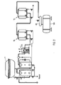
- Die vorliegende Erfindung wird nachfolgend unter Bezugnahme der folgenden Figuren näher erläutert werden:
- Fig. 1
- zeigt den schematischen Aufbau einer Ausführungsform der vorliegenden Erfindung,
- Fig. 2
- zeigt eine CO2-Rückgewinnungsanlage, wie sie aus dem Stand der Technik bekannt ist.
- Die erfindungsgemäße CO2-Rückgewinnungsanlage wird beim Brauen von Bier eingesetzt.
- Bei der erfindungsgemäßen CO2-Rückgewinnungsanlage wird zunächst wie beim Stand der Technik aerosolbeladenes CO2-Gas aus dem Gärbottich über eine CO2-Entnahmevorrichtung (nicht dargestellt) entnommen. Das abgeleitete CO2-Gas ist dabei aerosolbelastet. Der exakte Entstehungsort der Aerosole ist nicht wissenschaftlich nachgewiesen. Man geht jedoch davon aus, dass sie beim Drucksprung entstehen, welche Gasblasen beim Durchgang durch die Flüssigkeitsoberfläche im Fermenter verursachen.
- Mit vermehrter Anwendung von High-Gravity-Verfahren im Fermentationsbereich, d.h. bei Verwendung von hochprozentiger Würze (größer 12 %) treten vermehrt derartige Aerosole im CO2-Gas auf. Auch bei der Optimierung des Nettoinhalts der Fermenter (Reduzierung des Steigraums) werden vermehrt Aerosole beobachtet.
- Gemäß der vorliegenden Erfindung wird das aerosolbeladene CO2-Gas zunächst einem traditionellen Vorwäscher 4 über eine entsprechende Zuführung 9 zugeführt. Als traditionellen Gaswascher bezeichnet man beispielsweise Sprühdüsenwascher, Wascher mit eingebauten strukturierten Packungen (z.B. Sulzer-Mella Pach etc.) und Wascher mit Füllkörperfüllungen (z.B. Pallringe, Raschig-Ringe etc.). Der Gaswascher 4 entfernt wasserlösliche Verunreinigungen aus dem CO2. Die ausgewaschenen Verunreinigungen können über das Ventil 13 vom unteren Ende des Gaswaschers 4 abgeleitet werden. Die ausgewaschenen Verunreinigungen können über entsprechende Füllstandsensoren/Schalter LSH ( Niveau Hoch- Ventil 13 geöffnet) und LSL (Niveau tief - Ventil 13 geschlossen) niveaugesteuert abgeleitet werden. Es ist auch ein mechanisches Schwimmerventil (Klospülungsprinzip) möglich.
- Vom Ausgang 10 des Gaswaschers 4 wird das vorgereinigte immer noch mit Aerosolen beladene CO2-Gas dem Aerosolabscheider 1 über die Zuführung 5 zugeführt. Aerosolabscheider sind in der chemischen Verfahrenstechnik verbreitet im Einsatz, z.B. bei der Reinigung von Rauchgasen oder bei der Entfemung von Lösemitteln aus Luftströmen. Ein derartiger Aerosolabscheider besteht aus mindestens einem flächigen Abscheideelement 2, welches in einem Behälter 20 angeordnet ist. Bei der in Fig. 1 gezeigten Ausführungsform sind beispielsweise zwei rohrförmige Elemente 2a, 2b in dem Behälter angeordnet. Die Elementwände bestehen hier aus einem Kunststoffgewebe. Die Elemente sind stehend im Behälter 20 eingebaut. Das zu reinigende CO2-Gas wird in die Elemente 2a, b geleitet und verlässt die Elemente radial.
- Beim Durchströmen der Elemente werden aufgrund spezifischer Mechanismen, wie beispielsweise Diffusionseffekt, Trägheitsabscheidung und Sperreffekt, die Aerosole inklusive der mittransportierten Stoffe aus dem CO2-Gas entfernt. Das CO2-Gas kann den Abscheider 1 mehr oder weniger aerosolfrei über den Auslass 6 verlassen. Der Aerosolabscheider ermöglicht, dass annähemd 100 % aller Tröpfchen > 3 µm bis 99 % aller Tröpfchen < 3µm der Aerosole entfernt werden.
- Das in Zusammenhang mit Fig. 1 beschriebene Ausführungsbeispiel für einen Aerosolabscheider ist nur beispielhaft. So müssen die Elemente nicht rohrförmig ausgebildet sein, sondern können beispielsweise auch als Filtermatten gebildet werden, durch die das aerosolbeladene CO2-Gas durchströmt. Das Abscheideelement muss auch nicht zwangsläufig aus einem Kunststoffgewebe gebildet sein, sondem kann beispielsweise auch aus einem Glasfasergewebe oder einem Kunststoffnadelfilz, beispielsweise einem Polyesternadelfilz gebildet sein oder aus einem Vlies etc.
- Da bei der CO2-Rückgewinnung, die von den Aerosolen mitgetragenen Stoffe klebrig sind (wie vorab geschrieben diverse Zucker, etc.) ist es vorteilhaft, wie in Fig. 1 gezeigt, eine Bewässerungseinrichtung 3 vorzusehen. Die Bewässerungseinrichtung 3 ist in dem Gehäuse 20 des Aerosolabscheiders 1 vorgesehen. Hier weist die Bewässerungseinrichtung 3 einen Zulauf 8 für Wasser auf, sowie mehrere Düsen, die die Abscheideelemente 2a, 2b mit Wasser bedüsen. Das Wasser sammelt sich dann mit den abgeschiedenen Aerosolen und ihren Inhaltsstoffen am Behälterboden und kann dort über einen Ablauf 7 und ein entsprechendes Ventil 14 niveaugesteuert ausgeschleust werden. Dabei können wie im Zusammenhang mit dem Gaswascher 4 beschrieben entsprechende Füllstandssensoren/schalter LSH ( Niveau hoch - Ventil 14 auf) bzw. LSL ( Niveau niedrig - Ventil 14 zu) vorgesehen sein.
- Über den Auslass 6 kann dann von Aerosolen befreites CO2-Gas zu einem CO2-Zwischenspeicher, hier CO2-Ballon 11, geleitet werden. Von dem Ausgang 6 des Aerosolabscheiders 1 oder afternativ vom CO2-Ballon 11 kann das gereinigte CO2-Gas dann dem CO2-Kompressor 19 zugeführt werden, der das CO2-Gas, wie in Zusammenhang mit dem Stand der Technik beschrieben, verdichtet. Weiter kann die Einrichtung auch noch wie im Zusammenhang mit dem Stand der Technik beschrieben, eine Einrichtung zum Reinigen und Trocknen des komprimierten gekühlten CO2-Gases aufweisen, sowie eine CO2-Verflüssigungsanlage und einen CO2-Lagertank. Wie aus Fig. 1 hervorgeht, weist die Einrichtung hier auch noch eine Über-Unterdrucksicherung 12 für den CO2-Ballonbetrieb auf.
- Durch die Verwendung des Aerosolabscheiders 1 zusätzlich zu dem Gaswascher 4 kann das von wasserlöslichen Bestandteilen befreite CO2-Gas auch von Aerosolen und den darin mitgeführten Inhaltsstoffen befreit werden, so dass sich keine Aerosole und darin transportierte Inhaltsstoffe in der Rückgewinnungsanlage niederschlagen können. Insbesondere kann verhindert werden, dass Schäden durch Ablagerungen solcher Inhaltsstoffe in nachgeschalteten Anlageteilen der CO2-Rückgewinnungsanlage auftreten. Solche Schäden sind beispielsweise massive Korrosionserscheinungen von Rohrleitungen, Apparaten und Maschinen (meistens Lochfraß), Beeinträchtigung der Funktionsfähigkeit des CO2-Kompressors 19. Massive Verminderung der Standzeit der Arbeitsventile sowie mittelfristige Schädigung von Stopfbüchsen und Kolbenstangen, was zu einer Totalhavarie führen kann.
Claims (12)
- Anlage zum Rückgewinnen von bei der Gärung anfallendem CO2 mit einem CO2-Kompressor (19), dadurch gekennzeichnet, dass vor dem CO2-Kompressor (19) ein Aerosolabscheider (1) angeordnet ist.
- CO2-Rückgewinnungsanlage nach Anspruch 1, dadurch gekennzeichnet, dass der Aerosolabscheider (1) eine Bewässerungseinächtung (3) umfasst.
- CO2-Rückgewinnungsanlage nach Anspruch 2, dadurch gekennzeichnet, dass die Bewässerungseinrichtung (3) mindestens eine Düse umfasst.
- CO2-Rückgewinnungsanlage nach mindestens einem der Ansprüche 1 bis 3, dadurch gekennzeichnet, dass der Aerosolabscheider (1) zumindest ein flächiges Abscheideelement (2) umfasst, durch das das aerosolbeladene CO2-Gas strömt.
- CO2-Rückgewinnungsanlage nach einem der Ansprüche 2 bis 4, dadurch gekennzeichnet, dass die Bewässerungseinrichtung (3) das zumindest eine Abscheideelement (2) bewässert.
- CO2-Rückgewinnungsanlage nach mindestens einem der Ansprüche 1 bis 5, dadurch gekennzeichnet, dass vor dem Aerosolabscheider (1) ein Gaswascher (4) angeordnet ist.
- CO2-Rückgewinnungsanlage nach mindestens einem der Ansprüche 1 bis 6, dadurch gekennzeichnet, dass ein CO2-Gasballon (11) zwischen dem Aerosolabscheider und dem CO2-Kompressor (19) angeordnet ist.
- Verfahren zum Rückgewinnen von bei der Gärung anfallendem CO2, dadurch gekennzeichnet, dass vor dem Komprimieren das aerosolbeladene CO2-Gas einem Aerosolabscheider (1) zugeführt wird.
- Verfahren nach Anspruch 8, dadurch gekennzeichnet, dass während der Aerosolabscheidung das aerosolbeladene CO2 bzw. das mindestens eine Abscheideelement (2) bewässert wird.
- Verfahren nach einem der Ansprüche 8 oder 9, dadurch gekennzeichnet, dass das mit Aerosol beladene CO2-Gas vor der Aerosolabscheidung durch einen Gaswascher (4) geleitet wird.
- Verfahren nach einem der Ansprüche 8 bis 10, dadurch gekennzeichnet, dass das CO2-Gas vor dem Komprimieren einem CO2-Ballon zugeführt wird.
- Verwendung eines Aerosolabscheiders vor einem CO2-Kompressor bei der Rückgewinnung von bei der Gärung anfallendem CO2.
Priority Applications (7)
| Application Number | Priority Date | Filing Date | Title |
|---|---|---|---|
| DE502005000285T DE502005000285D1 (de) | 2005-02-16 | 2005-02-16 | Aerosolabscheider in einer Anlage zur Rückgewinnung von Kohlendioxid |
| AT05003306T ATE350465T1 (de) | 2005-02-16 | 2005-02-16 | Aerosolabscheider in einer anlage zur rückgewinnung von kohlendioxid |
| DK05003306T DK1693442T3 (da) | 2005-02-16 | 2005-02-16 | Aerosoludskiller i et anlæg til genindvinding af kuldioxid |
| EP05003306A EP1693442B1 (de) | 2005-02-16 | 2005-02-16 | Aerosolabscheider in einer Anlage zur Rückgewinnung von Kohlendioxid |
| BRPI0600109-2A BRPI0600109A (pt) | 2005-02-16 | 2006-01-13 | sistema e método de recuperação de co2, e uso de um separador de aerossol |
| US11/340,293 US8172926B2 (en) | 2005-02-16 | 2006-01-26 | Aerosol separator in CO2 recovery system |
| CNB2006100073718A CN100408665C (zh) | 2005-02-16 | 2006-02-13 | Co2回收系统中的气溶胶分离器 |
Applications Claiming Priority (1)
| Application Number | Priority Date | Filing Date | Title |
|---|---|---|---|
| EP05003306A EP1693442B1 (de) | 2005-02-16 | 2005-02-16 | Aerosolabscheider in einer Anlage zur Rückgewinnung von Kohlendioxid |
Publications (2)
| Publication Number | Publication Date |
|---|---|
| EP1693442A1 true EP1693442A1 (de) | 2006-08-23 |
| EP1693442B1 EP1693442B1 (de) | 2007-01-03 |
Family
ID=34933781
Family Applications (1)
| Application Number | Title | Priority Date | Filing Date |
|---|---|---|---|
| EP05003306A Expired - Lifetime EP1693442B1 (de) | 2005-02-16 | 2005-02-16 | Aerosolabscheider in einer Anlage zur Rückgewinnung von Kohlendioxid |
Country Status (7)
| Country | Link |
|---|---|
| US (1) | US8172926B2 (de) |
| EP (1) | EP1693442B1 (de) |
| CN (1) | CN100408665C (de) |
| AT (1) | ATE350465T1 (de) |
| BR (1) | BRPI0600109A (de) |
| DE (1) | DE502005000285D1 (de) |
| DK (1) | DK1693442T3 (de) |
Cited By (1)
| Publication number | Priority date | Publication date | Assignee | Title |
|---|---|---|---|---|
| US10478832B2 (en) | 2014-12-17 | 2019-11-19 | Krones Ag | Method and device for treating a mixture of expansion gas and filling product foam in a beverage filling plant |
Families Citing this family (3)
| Publication number | Priority date | Publication date | Assignee | Title |
|---|---|---|---|---|
| US8956671B1 (en) * | 2008-06-04 | 2015-02-17 | Ecopas Llc | Volatile organic compound recovery system and method |
| US20130130339A1 (en) | 2010-07-31 | 2013-05-23 | Myriant Corporation | Fermentation process for the production of organic acids |
| US10968419B1 (en) | 2017-05-07 | 2021-04-06 | Douglas J. Lanning | Fermentation byproduct management |
Citations (10)
| Publication number | Priority date | Publication date | Assignee | Title |
|---|---|---|---|---|
| DE890633C (de) * | 1951-05-11 | 1953-08-13 | Gesellschaft für Linde's Eismaschinen Aktiengesellschaft, Wiesbaden | Verfahren zum Auswaschen von Verunreinigungen aus Gasen, insbesondere aus Gärungskohlensäure |
| DE1223330B (de) * | 1958-08-30 | 1966-08-25 | Miller Brewing | Verfahren zur Reinigung der bei der Bierherstellung anfallenden Gaerungskohlensaeure |
| GB1566877A (en) * | 1976-10-07 | 1980-05-08 | Valvin Ets | Apparatus for providing purifed carbonic gas and recovering other vapours from the gaseous medium produced by fermenting liquids |
| EP0646756A1 (de) * | 1993-09-24 | 1995-04-05 | Haffmans B.V. | Herstellungsverfahren von reinem gasförmigem Kohlendioxid und Apparat zum Gebrauch dafür |
| US5425929A (en) * | 1990-10-24 | 1995-06-20 | Heineken Tech Services | Method of recovering substantially pure CO2 from fermentation gas |
| DE19755213A1 (de) * | 1997-01-30 | 1998-08-06 | Tecno Project Ind Srl | Verfahren zur Reinigung von Kohlensäure, die aus geeigneten Industrieverfahren, wie beispielsweise Gärungsprozessen, gewonnen wurde und angewendete Reinigungseinrichtungen |
| JP2000225183A (ja) * | 1999-02-09 | 2000-08-15 | Iwatani Internatl Corp | ガス精製系での再生用ガスの回収方法 |
| WO2003011757A1 (en) * | 2001-08-03 | 2003-02-13 | Haffmans B.V. | Apparatus for preparing pure carbon dioxide (co2) from a gaseous carbon dioxide containing product |
| EP1308502A1 (de) * | 2001-10-30 | 2003-05-07 | Anton Steinecker Maschinenfabrik GmbH | Verfahren zur Verflüssigung von CO2 aus der alkoholischen Gärung oder anderen Gasquellen |
| RU2237615C1 (ru) * | 2003-05-28 | 2004-10-10 | Харин Владимир Михайлович | Способ получения жидкого низкотемпературного диоксида углерода |
Family Cites Families (8)
| Publication number | Priority date | Publication date | Assignee | Title |
|---|---|---|---|---|
| DE1308502U (de) * | ||||
| US3733789A (en) * | 1972-03-13 | 1973-05-22 | Prat Daniel Poelman | Gas-liquid contacting apparatus for separating micromists from a carrier gas |
| US4140501A (en) * | 1975-12-12 | 1979-02-20 | Frank Ekman | Wet gas modular venturi scrubbing apparatus |
| DE3703824A1 (de) * | 1987-02-07 | 1988-08-18 | Thomae Gmbh Dr K | Verfahren zur simultanen chemischen und biologischen beseitigung fester und fluessiger organischer abfaelle und vorrichtungen zur durchfuehrung dieses verfahrens |
| CN2033010U (zh) * | 1988-03-02 | 1989-02-22 | 王涌铠 | 啤酒厂二氧化碳回收处理装置 |
| CN2070302U (zh) * | 1990-01-18 | 1991-01-30 | 黑龙江省应用技术咨询公司 | 啤酒敞口发酵产生气体的收集装置 |
| US5853439A (en) * | 1997-06-27 | 1998-12-29 | Donaldson Company, Inc. | Aerosol separator and method |
| US6143049A (en) * | 1997-06-27 | 2000-11-07 | Donaldson Company, Inc. | Aerosol separator; and method |
-
2005
- 2005-02-16 EP EP05003306A patent/EP1693442B1/de not_active Expired - Lifetime
- 2005-02-16 AT AT05003306T patent/ATE350465T1/de not_active IP Right Cessation
- 2005-02-16 DE DE502005000285T patent/DE502005000285D1/de not_active Expired - Lifetime
- 2005-02-16 DK DK05003306T patent/DK1693442T3/da active
-
2006
- 2006-01-13 BR BRPI0600109-2A patent/BRPI0600109A/pt not_active Application Discontinuation
- 2006-01-26 US US11/340,293 patent/US8172926B2/en not_active Expired - Fee Related
- 2006-02-13 CN CNB2006100073718A patent/CN100408665C/zh not_active Expired - Fee Related
Patent Citations (10)
| Publication number | Priority date | Publication date | Assignee | Title |
|---|---|---|---|---|
| DE890633C (de) * | 1951-05-11 | 1953-08-13 | Gesellschaft für Linde's Eismaschinen Aktiengesellschaft, Wiesbaden | Verfahren zum Auswaschen von Verunreinigungen aus Gasen, insbesondere aus Gärungskohlensäure |
| DE1223330B (de) * | 1958-08-30 | 1966-08-25 | Miller Brewing | Verfahren zur Reinigung der bei der Bierherstellung anfallenden Gaerungskohlensaeure |
| GB1566877A (en) * | 1976-10-07 | 1980-05-08 | Valvin Ets | Apparatus for providing purifed carbonic gas and recovering other vapours from the gaseous medium produced by fermenting liquids |
| US5425929A (en) * | 1990-10-24 | 1995-06-20 | Heineken Tech Services | Method of recovering substantially pure CO2 from fermentation gas |
| EP0646756A1 (de) * | 1993-09-24 | 1995-04-05 | Haffmans B.V. | Herstellungsverfahren von reinem gasförmigem Kohlendioxid und Apparat zum Gebrauch dafür |
| DE19755213A1 (de) * | 1997-01-30 | 1998-08-06 | Tecno Project Ind Srl | Verfahren zur Reinigung von Kohlensäure, die aus geeigneten Industrieverfahren, wie beispielsweise Gärungsprozessen, gewonnen wurde und angewendete Reinigungseinrichtungen |
| JP2000225183A (ja) * | 1999-02-09 | 2000-08-15 | Iwatani Internatl Corp | ガス精製系での再生用ガスの回収方法 |
| WO2003011757A1 (en) * | 2001-08-03 | 2003-02-13 | Haffmans B.V. | Apparatus for preparing pure carbon dioxide (co2) from a gaseous carbon dioxide containing product |
| EP1308502A1 (de) * | 2001-10-30 | 2003-05-07 | Anton Steinecker Maschinenfabrik GmbH | Verfahren zur Verflüssigung von CO2 aus der alkoholischen Gärung oder anderen Gasquellen |
| RU2237615C1 (ru) * | 2003-05-28 | 2004-10-10 | Харин Владимир Михайлович | Способ получения жидкого низкотемпературного диоксида углерода |
Non-Patent Citations (2)
| Title |
|---|
| DATABASE WPI Section Ch Week 200503, Derwent World Patents Index; Class E36, AN 2005-028326, XP002331226 * |
| PATENT ABSTRACTS OF JAPAN vol. 2000, no. 11 3 January 2001 (2001-01-03) * |
Cited By (2)
| Publication number | Priority date | Publication date | Assignee | Title |
|---|---|---|---|---|
| US10478832B2 (en) | 2014-12-17 | 2019-11-19 | Krones Ag | Method and device for treating a mixture of expansion gas and filling product foam in a beverage filling plant |
| US10864529B2 (en) | 2014-12-17 | 2020-12-15 | Krones Ag | Method and device for treating a mixture of expansion gas and filling product foam in a beverage filling plant |
Also Published As
| Publication number | Publication date |
|---|---|
| BRPI0600109A (pt) | 2006-10-03 |
| DE502005000285D1 (de) | 2007-02-15 |
| US20060185519A1 (en) | 2006-08-24 |
| US8172926B2 (en) | 2012-05-08 |
| ATE350465T1 (de) | 2007-01-15 |
| DK1693442T3 (da) | 2007-04-30 |
| CN1831100A (zh) | 2006-09-13 |
| EP1693442B1 (de) | 2007-01-03 |
| CN100408665C (zh) | 2008-08-06 |
Similar Documents
| Publication | Publication Date | Title |
|---|---|---|
| EP1485190B1 (de) | Verfahren zum entsäuern eines fluidstroms und waschflüssigkeit zur verwendung in einem derartigen verfahren | |
| DE2851847A1 (de) | Verfahren zum betrieb einer zyklisch arbeitenden druckwechsel-adsorptionsanlage | |
| DE69807462T2 (de) | Vorrichtung und verfahren zur gas-flüssigkeit mebran-absorption unter hohem druck | |
| WO2002089958A2 (de) | Verfahren zur reinigung von kokereigas | |
| EP0820802A2 (de) | Multiwäscher und Verfahren zur Totalreinigung von Gasen | |
| DE102015005203A1 (de) | Verfahren und Vorrichtung zur Zerlegung von Synthesegasen | |
| WO2010057581A1 (de) | Verfahren und vorrichtung zur waschmittelregenerierung in physikalischen gaswäschen | |
| DE69100469T2 (de) | Verfahren und Anlage zur Herstellung eines gasförmigen Bestandteils aus einer gasförmigen Mischung. | |
| EP3666364A1 (de) | Verfahren und vorrichtung zur regenerierung eines beladenen waschmittels aus einer gaswäsche | |
| DE3810705C2 (de) | ||
| EP1693442B1 (de) | Aerosolabscheider in einer Anlage zur Rückgewinnung von Kohlendioxid | |
| DE69904201T2 (de) | Verfahren und vorrichtung zur membranfiltration von wasser | |
| DE2729558A1 (de) | Adsorptions/desorptionsverfahren zur gewinnung von wasserstoff | |
| EP2498896A1 (de) | Verfahren und vorrichtung zur gaswäsche | |
| EP0328708A1 (de) | Verfahren zur Reinigung von Abluft | |
| DE3002920A1 (de) | Verfahren zum abtrennen von autopolymerisierbaren kohlenwasserstoffdaempfen aus luft | |
| WO2009143965A1 (de) | Aminwäsche | |
| DE3443390A1 (de) | Verfahren zur abtrennung von coffein aus verfluessigten oder ueberkritischen gasen | |
| EP2214804A1 (de) | Verfahren und vorrichtung zur regenerierung des beladenen waschmittels in einer physikalischen gaswäsche | |
| DE4412496C2 (de) | Verfahren zur verbesserten Rückgewinnung von Benzin- und/oder Lösemitteldämpfen in mit Druckkondensation und/oder Druckabsorption arbeitenden Anlagen zur Abluftreinigung | |
| WO2008043444A1 (de) | Waschsäule mit reduzierter bauhöhe | |
| EP2870992B1 (de) | Verfahren zur Reinigung einer Gaspermeationsmembran | |
| EP3583994A1 (de) | Anlage zur reinigung von rohsynthesegas mit turboexpander | |
| EP2456542A1 (de) | Verfahren und vorrichtung zur kombinierten physikalisch / chemischen abluftreinigung, abwasserreinigung, trinkwasser-desinfektion sowie zur gleichzeitigen abluft- und abwasserbehandlung | |
| BE1032989B1 (de) | Anlage und Verfahren zur Aufbereitung von Rohmethanol |
Legal Events
| Date | Code | Title | Description |
|---|---|---|---|
| GRAP | Despatch of communication of intention to grant a patent |
Free format text: ORIGINAL CODE: EPIDOSNIGR1 |
|
| PUAI | Public reference made under article 153(3) epc to a published international application that has entered the european phase |
Free format text: ORIGINAL CODE: 0009012 |
|
| GRAS | Grant fee paid |
Free format text: ORIGINAL CODE: EPIDOSNIGR3 |
|
| 17P | Request for examination filed |
Effective date: 20051109 |
|
| AK | Designated contracting states |
Kind code of ref document: A1 Designated state(s): AT BE BG CH CY CZ DE DK EE ES FI FR GB GR HU IE IS IT LI LT LU MC NL PL PT RO SE SI SK TR |
|
| GRAA | (expected) grant |
Free format text: ORIGINAL CODE: 0009210 |
|
| AK | Designated contracting states |
Kind code of ref document: B1 Designated state(s): AT BE BG CH CY CZ DE DK EE ES FI FR GB GR HU IE IS IT LI LT LU MC NL PL PT RO SE SI SK TR |
|
| PG25 | Lapsed in a contracting state [announced via postgrant information from national office to epo] |
Ref country code: SI Free format text: LAPSE BECAUSE OF FAILURE TO SUBMIT A TRANSLATION OF THE DESCRIPTION OR TO PAY THE FEE WITHIN THE PRESCRIBED TIME-LIMIT Effective date: 20070103 Ref country code: PL Free format text: LAPSE BECAUSE OF FAILURE TO SUBMIT A TRANSLATION OF THE DESCRIPTION OR TO PAY THE FEE WITHIN THE PRESCRIBED TIME-LIMIT Effective date: 20070103 Ref country code: FI Free format text: LAPSE BECAUSE OF FAILURE TO SUBMIT A TRANSLATION OF THE DESCRIPTION OR TO PAY THE FEE WITHIN THE PRESCRIBED TIME-LIMIT Effective date: 20070103 Ref country code: IE Free format text: LAPSE BECAUSE OF FAILURE TO SUBMIT A TRANSLATION OF THE DESCRIPTION OR TO PAY THE FEE WITHIN THE PRESCRIBED TIME-LIMIT Effective date: 20070103 |
|
| REG | Reference to a national code |
Ref country code: GB Ref legal event code: FG4D Free format text: NOT ENGLISH |
|
| REF | Corresponds to: |
Ref document number: 502005000285 Country of ref document: DE Date of ref document: 20070215 Kind code of ref document: P |
|
| REG | Reference to a national code |
Ref country code: IE Ref legal event code: FG4D Free format text: LANGUAGE OF EP DOCUMENT: GERMAN |
|
| PG25 | Lapsed in a contracting state [announced via postgrant information from national office to epo] |
Ref country code: MC Free format text: LAPSE BECAUSE OF NON-PAYMENT OF DUE FEES Effective date: 20070228 |
|
| PG25 | Lapsed in a contracting state [announced via postgrant information from national office to epo] |
Ref country code: BG Free format text: LAPSE BECAUSE OF FAILURE TO SUBMIT A TRANSLATION OF THE DESCRIPTION OR TO PAY THE FEE WITHIN THE PRESCRIBED TIME-LIMIT Effective date: 20070403 Ref country code: SE Free format text: LAPSE BECAUSE OF FAILURE TO SUBMIT A TRANSLATION OF THE DESCRIPTION OR TO PAY THE FEE WITHIN THE PRESCRIBED TIME-LIMIT Effective date: 20070403 |
|
| PG25 | Lapsed in a contracting state [announced via postgrant information from national office to epo] |
Ref country code: ES Free format text: LAPSE BECAUSE OF FAILURE TO SUBMIT A TRANSLATION OF THE DESCRIPTION OR TO PAY THE FEE WITHIN THE PRESCRIBED TIME-LIMIT Effective date: 20070414 |
|
| REG | Reference to a national code |
Ref country code: DK Ref legal event code: T3 |
|
| AKX | Designation fees paid |
Designated state(s): AT BE BG CH CY CZ DE DK EE ES FI FR GB GR HU IE IS IT LI LT LU MC NL PL PT RO SE SI SK TR |
|
| PG25 | Lapsed in a contracting state [announced via postgrant information from national office to epo] |
Ref country code: IS Free format text: LAPSE BECAUSE OF FAILURE TO SUBMIT A TRANSLATION OF THE DESCRIPTION OR TO PAY THE FEE WITHIN THE PRESCRIBED TIME-LIMIT Effective date: 20070503 |
|
| PG25 | Lapsed in a contracting state [announced via postgrant information from national office to epo] |
Ref country code: PT Free format text: LAPSE BECAUSE OF FAILURE TO SUBMIT A TRANSLATION OF THE DESCRIPTION OR TO PAY THE FEE WITHIN THE PRESCRIBED TIME-LIMIT Effective date: 20070604 |
|
| GBV | Gb: ep patent (uk) treated as always having been void in accordance with gb section 77(7)/1977 [no translation filed] |
Effective date: 20070103 |
|
| REG | Reference to a national code |
Ref country code: IE Ref legal event code: FD4D |
|
| EN | Fr: translation not filed | ||
| PLBE | No opposition filed within time limit |
Free format text: ORIGINAL CODE: 0009261 |
|
| PG25 | Lapsed in a contracting state [announced via postgrant information from national office to epo] |
Ref country code: SK Free format text: LAPSE BECAUSE OF FAILURE TO SUBMIT A TRANSLATION OF THE DESCRIPTION OR TO PAY THE FEE WITHIN THE PRESCRIBED TIME-LIMIT Effective date: 20070103 Ref country code: GB Free format text: LAPSE BECAUSE OF FAILURE TO SUBMIT A TRANSLATION OF THE DESCRIPTION OR TO PAY THE FEE WITHIN THE PRESCRIBED TIME-LIMIT Effective date: 20070103 |
|
| 26N | No opposition filed |
Effective date: 20071005 |
|
| PG25 | Lapsed in a contracting state [announced via postgrant information from national office to epo] |
Ref country code: CZ Free format text: LAPSE BECAUSE OF FAILURE TO SUBMIT A TRANSLATION OF THE DESCRIPTION OR TO PAY THE FEE WITHIN THE PRESCRIBED TIME-LIMIT Effective date: 20070103 Ref country code: RO Free format text: LAPSE BECAUSE OF FAILURE TO SUBMIT A TRANSLATION OF THE DESCRIPTION OR TO PAY THE FEE WITHIN THE PRESCRIBED TIME-LIMIT Effective date: 20070103 |
|
| PG25 | Lapsed in a contracting state [announced via postgrant information from national office to epo] |
Ref country code: LT Free format text: LAPSE BECAUSE OF FAILURE TO SUBMIT A TRANSLATION OF THE DESCRIPTION OR TO PAY THE FEE WITHIN THE PRESCRIBED TIME-LIMIT Effective date: 20070103 |
|
| PG25 | Lapsed in a contracting state [announced via postgrant information from national office to epo] |
Ref country code: FR Free format text: LAPSE BECAUSE OF FAILURE TO SUBMIT A TRANSLATION OF THE DESCRIPTION OR TO PAY THE FEE WITHIN THE PRESCRIBED TIME-LIMIT Effective date: 20070824 Ref country code: GR Free format text: LAPSE BECAUSE OF FAILURE TO SUBMIT A TRANSLATION OF THE DESCRIPTION OR TO PAY THE FEE WITHIN THE PRESCRIBED TIME-LIMIT Effective date: 20070404 |
|
| PG25 | Lapsed in a contracting state [announced via postgrant information from national office to epo] |
Ref country code: AT Free format text: LAPSE BECAUSE OF NON-PAYMENT OF DUE FEES Effective date: 20070216 |
|
| PG25 | Lapsed in a contracting state [announced via postgrant information from national office to epo] |
Ref country code: FR Free format text: LAPSE BECAUSE OF FAILURE TO SUBMIT A TRANSLATION OF THE DESCRIPTION OR TO PAY THE FEE WITHIN THE PRESCRIBED TIME-LIMIT Effective date: 20070103 |
|
| PG25 | Lapsed in a contracting state [announced via postgrant information from national office to epo] |
Ref country code: EE Free format text: LAPSE BECAUSE OF FAILURE TO SUBMIT A TRANSLATION OF THE DESCRIPTION OR TO PAY THE FEE WITHIN THE PRESCRIBED TIME-LIMIT Effective date: 20070103 |
|
| PLAA | Information modified related to event that no opposition was filed |
Free format text: ORIGINAL CODE: 0009299DELT |
|
| PLBE | No opposition filed within time limit |
Free format text: ORIGINAL CODE: 0009261 |
|
| STAA | Information on the status of an ep patent application or granted ep patent |
Free format text: STATUS: NO OPPOSITION FILED WITHIN TIME LIMIT |
|
| 26N | No opposition filed |
Effective date: 20071005 |
|
| RIN2 | Information on inventor provided after grant (corrected) |
Inventor name: BENDER, HARALD |
|
| PG25 | Lapsed in a contracting state [announced via postgrant information from national office to epo] |
Ref country code: CY Free format text: LAPSE BECAUSE OF FAILURE TO SUBMIT A TRANSLATION OF THE DESCRIPTION OR TO PAY THE FEE WITHIN THE PRESCRIBED TIME-LIMIT Effective date: 20070103 |
|
| PG25 | Lapsed in a contracting state [announced via postgrant information from national office to epo] |
Ref country code: LU Free format text: LAPSE BECAUSE OF NON-PAYMENT OF DUE FEES Effective date: 20070216 |
|
| PG25 | Lapsed in a contracting state [announced via postgrant information from national office to epo] |
Ref country code: TR Free format text: LAPSE BECAUSE OF FAILURE TO SUBMIT A TRANSLATION OF THE DESCRIPTION OR TO PAY THE FEE WITHIN THE PRESCRIBED TIME-LIMIT Effective date: 20070103 Ref country code: HU Free format text: LAPSE BECAUSE OF FAILURE TO SUBMIT A TRANSLATION OF THE DESCRIPTION OR TO PAY THE FEE WITHIN THE PRESCRIBED TIME-LIMIT Effective date: 20070704 |
|
| REG | Reference to a national code |
Ref country code: CH Ref legal event code: PL |
|
| PG25 | Lapsed in a contracting state [announced via postgrant information from national office to epo] |
Ref country code: CH Free format text: LAPSE BECAUSE OF NON-PAYMENT OF DUE FEES Effective date: 20090228 Ref country code: LI Free format text: LAPSE BECAUSE OF NON-PAYMENT OF DUE FEES Effective date: 20090228 |
|
| PGFP | Annual fee paid to national office [announced via postgrant information from national office to epo] |
Ref country code: NL Payment date: 20150210 Year of fee payment: 11 |
|
| PGFP | Annual fee paid to national office [announced via postgrant information from national office to epo] |
Ref country code: IT Payment date: 20150216 Year of fee payment: 11 Ref country code: DE Payment date: 20150210 Year of fee payment: 11 Ref country code: DK Payment date: 20150210 Year of fee payment: 11 |
|
| PGFP | Annual fee paid to national office [announced via postgrant information from national office to epo] |
Ref country code: BE Payment date: 20150211 Year of fee payment: 11 |
|
| PG25 | Lapsed in a contracting state [announced via postgrant information from national office to epo] |
Ref country code: BE Free format text: LAPSE BECAUSE OF NON-PAYMENT OF DUE FEES Effective date: 20160229 |
|
| REG | Reference to a national code |
Ref country code: DE Ref legal event code: R119 Ref document number: 502005000285 Country of ref document: DE |
|
| REG | Reference to a national code |
Ref country code: DK Ref legal event code: EBP Effective date: 20160229 |
|
| REG | Reference to a national code |
Ref country code: NL Ref legal event code: MM Effective date: 20160301 |
|
| PG25 | Lapsed in a contracting state [announced via postgrant information from national office to epo] |
Ref country code: IT Free format text: LAPSE BECAUSE OF NON-PAYMENT OF DUE FEES Effective date: 20160216 |
|
| PG25 | Lapsed in a contracting state [announced via postgrant information from national office to epo] |
Ref country code: DE Free format text: LAPSE BECAUSE OF NON-PAYMENT OF DUE FEES Effective date: 20160901 Ref country code: NL Free format text: LAPSE BECAUSE OF NON-PAYMENT OF DUE FEES Effective date: 20160301 Ref country code: DK Free format text: LAPSE BECAUSE OF NON-PAYMENT OF DUE FEES Effective date: 20160229 |