EP1693251A1 - Aufnahmestruktur für Kraftfahrzeug-Werkzeuge - Google Patents
Aufnahmestruktur für Kraftfahrzeug-Werkzeuge Download PDFInfo
- Publication number
- EP1693251A1 EP1693251A1 EP05101152A EP05101152A EP1693251A1 EP 1693251 A1 EP1693251 A1 EP 1693251A1 EP 05101152 A EP05101152 A EP 05101152A EP 05101152 A EP05101152 A EP 05101152A EP 1693251 A1 EP1693251 A1 EP 1693251A1
- Authority
- EP
- European Patent Office
- Prior art keywords
- tool storage
- carrier
- cover
- tool
- vehicle
- Prior art date
- Legal status (The legal status is an assumption and is not a legal conclusion. Google has not performed a legal analysis and makes no representation as to the accuracy of the status listed.)
- Granted
Links
Images


Classifications
-
- B—PERFORMING OPERATIONS; TRANSPORTING
- B60—VEHICLES IN GENERAL
- B60R—VEHICLES, VEHICLE FITTINGS, OR VEHICLE PARTS, NOT OTHERWISE PROVIDED FOR
- B60R11/00—Arrangements for holding or mounting articles, not otherwise provided for
- B60R11/06—Arrangements for holding or mounting articles, not otherwise provided for for tools or spare parts
Definitions
- the present invention relates to a vehicle tool storage structure capable of improving operability of taking out tools and efficiently using space.
- An actual vehicle tool storage structure is satisfactorily practical when a tool case or bag is used to store tools and is stored or attached to a specified part.
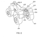
- FIG. 8 illustrates a conventional basic configuration.
- a vehicle tool storage structure 200 according to patent document 1 comprises: both rear fenders 202 to cover rear wheels 201; a rear cover to link these rear fenders 202; a cylindrical tool case 204 mounted on the top surface of the rear cover 203; and bands 206 to fix the tool case 204 to the rear cover 203.
- the tool case 204 is detachably placed on the rear cover 203.
- the vehicle tool storage structure 200 allows the tool case 204 to be placed on the rear cover 203.
- the tool case 204 becomes a hindrance to mounting other loads near the rear cover and the rear fenders 202, for example there has been the problem of being difficult to mount the other loads.
- the vehicle tool storage structure 200 uses the cylindrical tool case 204 to store onboard tools (not shown). Onboard tools are stored in the tool case 204 in a complicated manner, making it difficult to take out an intended onboard tool.
- the present invention provides a vehicle tool storage structure for a vehicle so configured that right-and-left wheels are rotatably mounted on a body frame, a body cover covers the body frame, and right-and-left fender sections are provided integrally with or independently of the body cover to cover the right-and-left wheels, wherein a carrier is disposed over the body cover so as to be able to mount loads; and wherein a tool storage section is provided to store onboard tools under the carrier.
- the carrier is disposed over the body cover so as to be able to mount loads.
- the tool storage section is provided to store onboard tools under the carrier.
- the carrier is disposed over the body cover so as to be able to mount loads.
- the tool storage section is provided to store onboard tools under the carrier. In this manner, onboard tools are stored so as not to prevent loads from being mounted.
- the present invention according to claim 2 is characterized in that the tool storage section is configured as a drawable tool tray on the carrier.
- the tool storage section is configured as a drawable tool tray on the carrier. In this manner, intended onboard tools can be taken out easily.
- the present invention according to claim 3 is characterized in that the tool tray has a concave section approximately shaped to the onboard tools.
- the tool tray has a concave section approximately shaped to the onboard tools. In this manner, onboard tools can be stored orderly.
- the carrier is disposed over the body cover so as to be able to mount loads.
- the tool storage section is provided to store onboard tools under the carrier. In this manner, onboard tools can be stored so as not to prevent loads from being mounted. As a result, there is an advantage of ensuring a sufficient amount of loads.
- the tool storage section is configured as a drawable tool tray on the carrier.
- intended onboard tools can be taken out easily.
- the tool tray has a concave section approximately shaped to the onboard tools.
- FIG. 1 is a side view of a vehicle that uses the tool storage structure according to the present invention.
- a vehicle 10 represents vehicles used on uneven roads.
- a steering shaft 12 is mounted on the front of a body frame 11. The bottom of the steering shaft 12 is coupled to right-and-left front wheels 13 and 14 as wheels.
- FIG. 1 shows only the front wheel 13 nearer to the viewer.
- a handle 15 is mounted on the top of the steering shaft 12.
- a middle of the body frame 11 is mounted with a power unit comprising an engine 16 and a transmission 17.
- Rear wheels 21 and 22 are disposed at the rear of the body frame 11 and are driven by the power unit 18 together with the front wheels 13 and 14.
- FIG. 1 shows only the rear wheel 21 nearer to the viewer.
- reference numeral 24 denotes a front grille to cover the body front
- 25 and 26 denote headlamps (showing only reference numeral 25 nearer to the viewer);
- 27 denotes a shock absorber (showing only one of both reference numerals) for the front wheels 13 and 14;
- 28 denotes a fuel tank mounted on the body frame 11;
- 29 denotes an exhaust system that is connected to the front of the engine 16 and is bent to be extended toward the rear;
- 31 denotes a carburetor connected to the rear of the engine 16;
- 32 denotes an air cleaner system connected to the rear of the carburetor 31;
- 33 denotes an air vent to cause an atmospheric pressure on fuel surface of a float chamber provided in the carburetor 31;
- 34 denotes a front carrier to mount loads;
- 35 denotes a front cover to be used as a body cover for covering the front of the body;
- 36 denotes a carrier stay (carrier pipe) mounted on the body frame 11
- FIG. 2 is a top view of the vehicle that uses the tool storage structure according to the present invention.
- Right-and-left main frames 55 constitute part of the body frame 11 and are disposed in the center of the body so as to be extended along a cross direction. Between the main frames 55, there are disposed a power unit 18, the carburetor 40, a main air cleaner 56 constituting the air cleaner system 32.
- the exhaust system 29 is bent in a U shape from the engine 16 and is extended toward the rear.
- a handle supporting member 53 is mounted above the steering shaft 12.
- the handle 15 is mounted on the handle supporting member 53 via handle clamping members 54.
- the mud guards 45 are disposed on the right and left sides of the body so as to sandwich a license plate 58.
- FIG. 3 is a partial side view of the vehicle tool storage structure according to the present invention.
- a vehicle tool storage structure 60 comprises: a front cover 35 having right-and-left fender sections 37 and 38 each to cover the right-and-left front wheels 13 and 14 (see FIG. 2); a front carrier 34 provided above the front cover 35 to mount loads; and a tool storage structure 61 provided under the front carrier to store onboard tools.
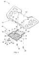
- FIG. 4 is an exploded perspective view of the vehicle tool storage structure according to the present invention.
- the front carrier 34 comprises: a mounting section 62 to mount loads; right-and-left guide grooves 63 formed under the front of the mounting section 62 to drawably guide the tool storage section 61; right-and-left mounting bosses 64 formed under the mounting section 62 to drawably mount the tool storage section 61; and a hook section 65 formed on the front of the mounting section 62 to hook the tool storage section 61.
- the tool storage section 61 is a tool tray drawably mounted on the front carrier 34.
- the tool storage section 61 comprises: a tray body 78 to store onboard tools 70 through 77; and a hook lever 79 rotatably mounted on the tray body 78 to be engaged with the hook section 65.
- the tray body 78 comprises: right-and-left rails 81 formed on both sides thereof to each engage with right-and-left guide grooves 63; extended sections 82 extending from the rear; long holes 83 each formed in the extended sections 82; concave sections 84 through 86 approximately matching shapes of onboard tools 70 through 77; and a mounting section 87 to rotatably mount the hook lever 79.
- the concave section 84 approximately matches an onboard tool 70.
- the concave section 85 approximately matches an onboard tool 71.
- the concave section 86 approximately matches onboard tools 72 through 77.
- Reference numerals 88 denote bolts (screws) that are fit to mounting bosses 64 to slidably guide the long holes 83.
- the hook lever 79 comprises: projections 91 fit to the mounting section of the tray body 78; an aperture 92 to engage with the hook section 65; and a tab 93 to engage with or disengage from the hook section 65.
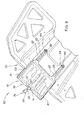
- FIG. 5 is a perspective view showing that the tool storage section is drawn from the vehicle tool storage structure according to the present invention.
- the vehicle tool storage structure 60 is used with the vehicle 10 configured as follows.
- the body frame 11 is rotatively mounted with the right-and-left front wheels (wheels) 13 and 14 as shown in FIG. 2.
- the front cover (body cover) 35 covers the body frame 11.
- the front cover 35 is integrally formed with the right-and-left fender sections 37 and 38 to cover the right-and-left front wheels 13 and 14.
- the front carrier (carrier) 34 is disposed over the front cover 35 to mount loads.
- the tool storage section (tool tray) 61 is provided under the front carrier 34 so as to store the onboard tools 70 through 77.
- the front carrier (carrier) 34 is disposed over the front cover (body cover) 35 so as to be able to mount loads.
- the tool storage section (tool tray) 61 is provided to store the onboard tools 70 through 77 under the front carrier 34. In this manner, the onboard tools 70 through 77 can be stored so as not to prevent loads from being mounted. As a result, it is possible to ensure a sufficient amount of loads.
- the vehicle tool storage structure 60 may be also considered to be the tool storage section (tool tray) 61 having the concave sections 84 through 86 approximately matching shapes of the onboard tools 70 through 77.
- the tool storage section (tool tray) 61 has the concave sections 84 through 86 approximately matching shapes of the onboard tools 70 through 77.
- the onboard tools 70 through 77 can be stored orderly. As a result, it is possible to improve the operability of taking out tools.
- FIG. 6 is a perspective view taken in the direction of the arrow of FIG. 5 and shows the bottom of the vehicle tool storage structure 60.
- the vehicle tool storage structure 60 indicates that the tool storage section 61 is provided as a drawable tool tray on the front carrier (carrier) 34.
- the tool storage section 61 is provided as a drawable tool tray on the front carrier (carrier) 34, the intended onboard tools 70 through 77 (see FIG. 5) can be taken out easily.
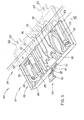
- FIG. 7 is an exploded perspective view of the vehicle tool storage structure according to another embodiment of the present invention.
- the same reference numerals are used to depict the same parts as used for the vehicle tool storage structure 60 (see FIGS. 2 and 4) and a detailed description is omitted for simplicity.
- a vehicle tool storage structure 100 comprises the front cover 35, a front carrier 104, and a tool storage section 101.
- the front cover 35 has the right-and-left fender sections 37 and 38 to cover the right-and-left front wheels 13 and 14 (see FIG. 2), respectively.
- the front carrier 104 a carrier made of pipes, is provided over the front cover 35 to mount loads.
- the tool storage section 101 is provider under the front carrier 104 to store the onboard tools 70 through 77.
- the tool storage section 101 comprises a storage base 102 and a tool tray 103.
- the storage base 102 is attached to the front carrier 104.
- the tool tray 103 is drawably mounted on the storage base 102 and stores the onboard tools 70 through 77.
- Reference numeral 105 denotes a bolt to mount the storage base 102 on the front carrier 104; and 106... denotes a bolt hole formed in the front carrier 104. Ellipsis points ... indicate that a plurality of corresponding components are provided. The same applies to the following description.
- the storage base 102 is formed with: support sections 112... that are formed in a body 111 to be fixed to the front carrier 104; right-and-left guide grooves 113 formed under the body 111; and a hook section 114 to hook the tool tray 103.
- the support sections 112... are formed with through holes 115... to insert bolts 105...
- the tool tray 103 comprises: a tray body 118 to store the onboard tools 70 through 77; and the hook lever 79 rotatably mounted on the tray body 118 to be engaged with the hook section 114.
- the tray body 118 comprises: right-and-left rails 121 formed on both sides thereof to each engage with right-and-left guide grooves 113; concave sections 124 through 126 approximately matching shapes of the onboard tools 70 through 77; and a mounting section 127 to rotatably mount the hook lever 79.
- vehicle tool storage structure 60 has the tool storage section 61 formed on the front carrier 34 as shown in FIG. 3, the present invention is not limited thereto.
- the tool storage section may be provided on the rear carrier.
- vehicle tool storage structure 60 is provided with the common concave section 86 to store the onboard tools 72 through 77 as shown in FIG. 5, the present invention is not limited thereto. Individual concave sections may be provided to store individual onboard tools.
- the vehicle tool storage structure according to the present invention is appropriately applicable to vehicles used on uneven roads such as 4-wheel buggy.
Priority Applications (3)
| Application Number | Priority Date | Filing Date | Title |
|---|---|---|---|
| EP20050101152 EP1693251B1 (de) | 2005-02-16 | 2005-02-16 | Aufnahmestruktur für Kraftfahrzeug-Werkzeuge |
| ES05101152T ES2363603T3 (es) | 2005-02-16 | 2005-02-16 | Estructura de almacenamiento de herramientas de vehículo. |
| PT05101152T PT1693251E (pt) | 2005-02-16 | 2005-02-16 | Estrutura de armazenagem de ferramentas de veículo |
Applications Claiming Priority (1)
| Application Number | Priority Date | Filing Date | Title |
|---|---|---|---|
| EP20050101152 EP1693251B1 (de) | 2005-02-16 | 2005-02-16 | Aufnahmestruktur für Kraftfahrzeug-Werkzeuge |
Publications (2)
| Publication Number | Publication Date |
|---|---|
| EP1693251A1 true EP1693251A1 (de) | 2006-08-23 |
| EP1693251B1 EP1693251B1 (de) | 2011-03-30 |
Family
ID=34938745
Family Applications (1)
| Application Number | Title | Priority Date | Filing Date |
|---|---|---|---|
| EP20050101152 Not-in-force EP1693251B1 (de) | 2005-02-16 | 2005-02-16 | Aufnahmestruktur für Kraftfahrzeug-Werkzeuge |
Country Status (3)
| Country | Link |
|---|---|
| EP (1) | EP1693251B1 (de) |
| ES (1) | ES2363603T3 (de) |
| PT (1) | PT1693251E (de) |
Cited By (1)
| Publication number | Priority date | Publication date | Assignee | Title |
|---|---|---|---|---|
| WO2007060308A1 (fr) * | 2005-11-21 | 2007-05-31 | Nexter Systems | Dispositif de fixation d'un coffre logistique et coffre logistique mettant en œuvre un tel dispositif |
Citations (4)
| Publication number | Priority date | Publication date | Assignee | Title |
|---|---|---|---|---|
| US2981554A (en) * | 1960-09-02 | 1961-04-25 | Marvin W Mulder | Tool box and step assembly |
| US6296163B1 (en) | 1998-07-09 | 2001-10-02 | Kawasaki Jukogyo Kabushiki Kaisha | Carrier for straddle type four wheeled all-terrain vehicle and support structure therefor |
| US20020088661A1 (en) * | 1997-04-10 | 2002-07-11 | Claude Gagnon | All terrain vehicle |
| EP1371520A2 (de) * | 2002-06-13 | 2003-12-17 | Arctic Cat Inc. | Gepäckträger für Freizeitfahrzeuge |
-
2005
- 2005-02-16 EP EP20050101152 patent/EP1693251B1/de not_active Not-in-force
- 2005-02-16 PT PT05101152T patent/PT1693251E/pt unknown
- 2005-02-16 ES ES05101152T patent/ES2363603T3/es active Active
Patent Citations (4)
| Publication number | Priority date | Publication date | Assignee | Title |
|---|---|---|---|---|
| US2981554A (en) * | 1960-09-02 | 1961-04-25 | Marvin W Mulder | Tool box and step assembly |
| US20020088661A1 (en) * | 1997-04-10 | 2002-07-11 | Claude Gagnon | All terrain vehicle |
| US6296163B1 (en) | 1998-07-09 | 2001-10-02 | Kawasaki Jukogyo Kabushiki Kaisha | Carrier for straddle type four wheeled all-terrain vehicle and support structure therefor |
| EP1371520A2 (de) * | 2002-06-13 | 2003-12-17 | Arctic Cat Inc. | Gepäckträger für Freizeitfahrzeuge |
Cited By (1)
| Publication number | Priority date | Publication date | Assignee | Title |
|---|---|---|---|---|
| WO2007060308A1 (fr) * | 2005-11-21 | 2007-05-31 | Nexter Systems | Dispositif de fixation d'un coffre logistique et coffre logistique mettant en œuvre un tel dispositif |
Also Published As
| Publication number | Publication date |
|---|---|
| PT1693251E (pt) | 2011-06-15 |
| EP1693251B1 (de) | 2011-03-30 |
| ES2363603T3 (es) | 2011-08-10 |
Similar Documents
| Publication | Publication Date | Title |
|---|---|---|
| US20220024354A1 (en) | Vehicle | |
| US7303221B2 (en) | Vehicle tool storage structure | |
| US7311170B2 (en) | All terrain vehicle | |
| US20110049205A1 (en) | System for mounting a box or bag to a vehicle | |
| JP5112237B2 (ja) | 自動二輪車のバッテリ配置構造 | |
| US8177259B2 (en) | Canister mounting structure | |
| JP5129632B2 (ja) | 鞍乗り型車両のハーネス保持構造 | |
| US7134702B2 (en) | Structure for supporting headlamps for vehicle | |
| US7490693B2 (en) | Grab rail and muffler support structure | |
| US7604382B2 (en) | Vehicle component assembly for a straddle type vehicle | |
| JP2011143834A (ja) | 車両 | |
| US8042636B2 (en) | Saddle-ride type four-wheel vehicle | |
| US7350854B2 (en) | Rear fender and rear carrier bar | |
| EP3150474B1 (de) | Batteriefach für sattelfahrzeug | |
| EP1693251B1 (de) | Aufnahmestruktur für Kraftfahrzeug-Werkzeuge | |
| EP0581318A2 (de) | Rahmenstruktur für Motorrad | |
| JP3470575B2 (ja) | 自動二輪車の収納箱内工具収納装置 | |
| JP6021676B2 (ja) | 電気動力車両の車体構造 | |
| JP5277123B2 (ja) | 鞍乗り型車両のリヤ構造 | |
| JP4040418B2 (ja) | 車両用エアクリーナ装置 | |
| US20040178619A1 (en) | Steering shaft support structure for vehicle for uneven ground running | |
| JP2513688Y2 (ja) | エンジン横置き型車両 | |
| JP7193389B2 (ja) | 作業車 | |
| US20090243275A1 (en) | Saddle-type vehicle including wheel well shields and an underbody splash guard member | |
| JP2001239972A (ja) | スクータ型自動二輪車の収納装置 |
Legal Events
| Date | Code | Title | Description |
|---|---|---|---|
| PUAI | Public reference made under article 153(3) epc to a published international application that has entered the european phase |
Free format text: ORIGINAL CODE: 0009012 |
|
| AK | Designated contracting states |
Kind code of ref document: A1 Designated state(s): AT BE BG CH CY CZ DE DK EE ES FI FR GB GR HU IE IS IT LI LT LU MC NL PL PT RO SE SI SK TR |
|
| AX | Request for extension of the european patent |
Extension state: AL BA HR LV MK YU |
|
| 17P | Request for examination filed |
Effective date: 20070208 |
|
| AKX | Designation fees paid |
Designated state(s): ES FR PT |
|
| REG | Reference to a national code |
Ref country code: DE Ref legal event code: 8566 |
|
| 17Q | First examination report despatched |
Effective date: 20081126 |
|
| GRAP | Despatch of communication of intention to grant a patent |
Free format text: ORIGINAL CODE: EPIDOSNIGR1 |
|
| GRAC | Information related to communication of intention to grant a patent modified |
Free format text: ORIGINAL CODE: EPIDOSCIGR1 |
|
| GRAS | Grant fee paid |
Free format text: ORIGINAL CODE: EPIDOSNIGR3 |
|
| GRAA | (expected) grant |
Free format text: ORIGINAL CODE: 0009210 |
|
| AK | Designated contracting states |
Kind code of ref document: B1 Designated state(s): ES FR PT |
|
| REG | Reference to a national code |
Ref country code: PT Ref legal event code: SC4A Free format text: AVAILABILITY OF NATIONAL TRANSLATION Effective date: 20110606 |
|
| REG | Reference to a national code |
Ref country code: ES Ref legal event code: FG2A Ref document number: 2363603 Country of ref document: ES Kind code of ref document: T3 Effective date: 20110810 |
|
| PLBE | No opposition filed within time limit |
Free format text: ORIGINAL CODE: 0009261 |
|
| STAA | Information on the status of an ep patent application or granted ep patent |
Free format text: STATUS: NO OPPOSITION FILED WITHIN TIME LIMIT |
|
| 26N | No opposition filed |
Effective date: 20120102 |
|
| PGFP | Annual fee paid to national office [announced via postgrant information from national office to epo] |
Ref country code: FR Payment date: 20120221 Year of fee payment: 8 |
|
| PGFP | Annual fee paid to national office [announced via postgrant information from national office to epo] |
Ref country code: PT Payment date: 20120215 Year of fee payment: 8 |
|
| PGFP | Annual fee paid to national office [announced via postgrant information from national office to epo] |
Ref country code: ES Payment date: 20120307 Year of fee payment: 8 |
|
| REG | Reference to a national code |
Ref country code: PT Ref legal event code: MM4A Free format text: LAPSE DUE TO NON-PAYMENT OF FEES Effective date: 20130816 |
|
| PG25 | Lapsed in a contracting state [announced via postgrant information from national office to epo] |
Ref country code: PT Free format text: LAPSE BECAUSE OF NON-PAYMENT OF DUE FEES Effective date: 20130816 |
|
| REG | Reference to a national code |
Ref country code: FR Ref legal event code: ST Effective date: 20131031 |
|
| PG25 | Lapsed in a contracting state [announced via postgrant information from national office to epo] |
Ref country code: FR Free format text: LAPSE BECAUSE OF NON-PAYMENT OF DUE FEES Effective date: 20130228 |
|
| REG | Reference to a national code |
Ref country code: ES Ref legal event code: FD2A Effective date: 20140408 |
|
| PG25 | Lapsed in a contracting state [announced via postgrant information from national office to epo] |
Ref country code: ES Free format text: LAPSE BECAUSE OF NON-PAYMENT OF DUE FEES Effective date: 20130217 |