EP1693198A2 - Machine d'impression de feuilles - Google Patents
Machine d'impression de feuilles Download PDFInfo
- Publication number
- EP1693198A2 EP1693198A2 EP06002328A EP06002328A EP1693198A2 EP 1693198 A2 EP1693198 A2 EP 1693198A2 EP 06002328 A EP06002328 A EP 06002328A EP 06002328 A EP06002328 A EP 06002328A EP 1693198 A2 EP1693198 A2 EP 1693198A2
- Authority
- EP
- European Patent Office
- Prior art keywords
- sheet
- printing machine
- machine according
- fed printing
- printed sheets
- Prior art date
- Legal status (The legal status is an assumption and is not a legal conclusion. Google has not performed a legal analysis and makes no representation as to the accuracy of the status listed.)
- Withdrawn
Links
Images

Classifications
-
- B—PERFORMING OPERATIONS; TRANSPORTING
- B41—PRINTING; LINING MACHINES; TYPEWRITERS; STAMPS
- B41F—PRINTING MACHINES OR PRESSES
- B41F23/00—Devices for treating the surfaces of sheets, webs, or other articles in connection with printing
Definitions
- the invention relates to a sheet-fed printing machine according to the preamble of claim 1.
- Sheet-fed printing presses are used for printing sheet-like substrates, so-called printing sheet, whereby printed sheets to be printed are introduced into the printing process in the area of an investor and are discharged from the printing process in the area of a delivery arm. Between the feeder and the boom of the printing press several printing units are positioned, wherein in each printing unit, a partial printing image is applied in a special ink on the substrate.
- the printed sheets to be printed can be made of a variety of different materials. If printed sheets designed as plastic films or provided with a plastic coating are to be printed, then it should be noted that in particular UV-curing printing inks or water-based printing inks adhere only very poorly to the printed sheet. This is especially the case when printing sheets from difficult to print substrates or corresponding coatings such as polypropylene (PP, HDPP, LDPP) or polyethylene (PE, HDPE, LDPE) are to be printed. Thus, these plastics are materials which, due to their production, have a low surface tension and / or a low polarity. This results in printing with UV-curable inks or water-based inks or paints poor wetting such sheets and / or poor adhesion of the ink or varnish.
- DE 102 32 255 A1 discloses a device for treating the surfaces of printing substrates in printing machines, wherein the printing material is bombarded with electrons in the region of a corona electrode.
- a printing cylinder on which the printing material is guided while moving past the corona electrode, serves as a counterelectrode, so that an electrical discharge, which is carried out between the corona electrode and the printing cylinder serving as the counterelectrode, takes place through the printing material.
- a small distance of the corona electrode from the substrate in the order of 0.5 mm must be maintained, so that accessibility is severely limited.
- DE 20 2004 008 285 U1 discloses an atmospheric pressure plasma processing tool for wide workpieces in which electrical discharges occur between electrodes and counter electrodes formed as nozzles.
- the electrodes and the counter electrodes formed as a nozzle are positioned on one side of a substrate to be treated so that the electrical discharge does not occur through the substrate.
- a plasma generated during the electric corona discharge is conducted by means of a gas, namely with the aid of compressed air, onto the surface of the substrate to be treated.
- a gas namely with the aid of compressed air
- other gases for example nitrogen, can be used to transport the plasma in the direction of the substrate.
- the present invention is based on the problem to provide a novel sheet-fed printing machine.
- the or each device for surface modification of substrates in the area of the feeder and / or a sheet turning device and / or in front of a coating unit is integrated into the sheet-fed printing machine.
- the or each device arranged according to the invention for surface modification preferably generates a plasma on the respective one side of a printing material assigned to it. Accordingly, the printing material is not positioned between the electrodes, between which an electrical charge takes place for plasma formation.
- the plasma generated by means of electrical discharges from air or other gases, such as nitrogen, for example, is conducted by means of overpressure onto the respective surface of the printing material.
- the feeder is designed as a bulkhead feeder and has an investment table on which the printed sheets are transported as scale flow, wherein the device for surface modification is integrated into the area of the flaker feeder, in which the surface of the sheet to be modified freely accessible is. Preferably, it takes place in an area for alignment and singulation of the printed sheets.
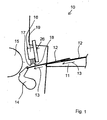
- Fig. 1 shows a schematic section of a sheet-fed printing machine according to the invention in the region of an investor 10.
- the feeder 10 is designed as a flaky feeder, which means that in the area of the feed table 11, printed sheets 12 are transported with overlapping as a shingled stream.
- Fig. 1 shows schematically two mutually partially overlapping printed sheets 12 of a scale flow.
- the transfer gripper 14 detects a sheet 12 at its front in the transport direction section, pulls this from Investment table 11 from and then passes this to a first cylinder 15 of the printing press.
- a device 16 for surface modification of the printed sheets 12 to be printed is integrated into the area of the feeder 10 of the sheet-fed printing machine.
- the device 16 for surface modification is integrated into the feeder 10 in such a way that it is positioned in the region of the transfer gripper 14, ie in the region of the feeder 10 in which the printing sheet 12 is aligned and singulated , In this area, the sheet to be processed is exposed and its surface is fully accessible. This ensures that the printed sheets 12 can be subjected to a surface modification over their entire surface.
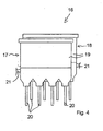
- the device 16 for surface modification of the substrates 12 by means of a plasma is preferably designed as shown in FIG. 4.
- the device 16 of FIG. 4 has a plurality of electrodes, which are grouped in two consecutive rows 17 and 18, respectively. Within each of these two rows 17 and 18, four electrodes are arranged in a common housing 19 in the illustrated embodiment, with nozzles 20 of the housing 19 forming counterelectrodes for electrical discharge within the device 16.
- the number of rows and the associated number of electrodes per row are listed here purely by way of example.
- the device 16 is mounted on a cross member 26 according to FIG. 1.
- the nozzles 20 and the electrodes (not shown) of the two rows 17 and 18 are aligned with each other such that in the middle between two adjacent electrodes or nozzles 20 of one row an electrode or nozzle 20 of an adjacent one Row is positioned.
- an array of electrodes or nozzles 20 is formed by means of which the printing materials 12 can be uniformly subjected to a surface modification in the region of their surface.
- a flowing under pressure carrier gas eg compressed air 21
- the nozzles 20 are preferably designed as slit nozzles and have seen in cross section parallel to the conveying plane and transverse to the direction of movement of the sheet 12 over a larger dimension than in the direction of movement of the sheet to be treated 12. This allows a particularly uniform treatment of the sheet 12 can be realized.
- FIGS. 2 and 3 show a device 22 for the surface modification of substrates, wherein electrical discharges take place between in each case two outer electrodes 23. Between the electrodes 23, a plasma 24 is formed, which can be directed under the pressure of the compressed air 25 on a surface of the printed sheet 12 to be treated.
- the devices 16 and 22 for surface modification of printed sheets are arranged by means of a holder in the abutment region of the printing press. At this point they can be pivoted into a working position on the bow path.
- the devices 16 and 22 can also be designed to be swivelable out of the contact area.
- the units 16, 22 integrated in the contact area of the sheet-fed printing machine for the surface modification of printed sheets can finally be clad by corresponding protection.
- the protection can be made possible by means of a suction unit, the removal of the resulting warm process gases by means of a negative pressure. This will be environmental pollution avoided on site and an inadmissible heating of the units 16 and 22 by the working process can be prevented.
- a device 16 for surface modification is positioned in the region of the feeder 10, with the aid of which the printed sheets 12 can be treated in the region of an upper side or surface with respect to an arcuate path.
- a device 16 for surface modification on both sides of the printing material.
- a second device for surface modification in FIG. 1 may be positioned below the alignment region of the feeder 10 or below the cylinder 15 and thus take over the surface modification of the printing substrate in the region of its second side.
- the second surface modification device in the area of a sheet turning device can be integrated into the printing machine.
- the second device for surface modification is preferably arranged in the region after the application of the sheet, where the printed sheet 12 is everted and thus its second side is upwards. Then the device 16 for surface modification can be arranged above the arcuate path.
- a third device for surface modification can be integrated in front of a coating unit in the sheet-fed press.
- the device for surface modification is also possible to integrate the device for surface modification exclusively in the area of a sheet turn in the sheet-fed press. This is advantageous if one-sided coated printing sheets are used, which should initially print from the uncoated side and after the sheet application of the coated side.
- the device for surface modification is also possible to integrate the device for surface modification exclusively in front of a coating unit in the sheet-fed press. This is advantageous if the already printed surface of the signature for a final Finishing treatment, eg by applying a glossy or protective coating, to be modified.
- means for surface modification are used in which the electrical discharge does not occur through the substrate, in which therefore electrodes and counterelectrodes, between each of which electrical discharges occur on each side of a treated Sheet are positioned.
- the device for surface modification in this case has a distance of between 5 mm and 10 mm from the respective surface of the printed sheets.
- the means 16 or 22 for modifying the surface of printed sheets is either provided with its own control in addition to the power supply or may be coupled to the machine control in such a way that it is adaptable in its behavior to the printing process.
- At least the time or the time duration or time and duration of the plasma generation by means of the device 16 or 22 can initially be set. These adjustments may also be tunable with respect to the power stroke of the sheetfed press.
- the means 16 or 22 for generating the plasma used in the modification of the sheet surface can thus be limited in an efficient manner to the time during the supply of a sheet in the sheet-fed press. This prevents charges from being scattered uncontrollably into the printing machine or into the feeder 10.
- activation of the device 16 for surface modification of printed sheets can take place such that regions of the substrate surface are recessed both transversely and longitudinally relative to the feed direction. This is due to the described design of the device 16 from a series of discharge units.
- the amount of plasma generation is adjustable to provide, in relation to the desired pressure conditions, the necessary amount of free radicals in an adaptable plasma for e.g. to achieve different adjustments of surface tensions in the modification of the surface of the printed sheets.
- the power of the discharge units is variably controlled, so that the amount of reactive plasma gas can be influenced in a targeted manner.
- the strength of the surface modification of printed sheets by the plasma on the respective substrate is adjustable.
- differences arise between different substrates to be processed, as they react differently with the free radicals from the plasma.
- This reaction may also be variable for inherently similar materials due to variable manufacturing processes, transportation and storage conditions. Therefore, the strength of the surface modification is specifically influenced, with the main influence variable being the strength of the plasma.
- the duration of the plasma action, the type of gas used and the overpressure at the nozzles also have an effect.
- the strength of the surface modification of the printed sheets can also be adapted to the transport speed of the printed sheets to be processed by means of the mentioned control.
- the strength of the plasma can be increased, so that even in a shorter time always the same amount of reactive plasma gas is available.
- the overpressure to impress the plasma gas on the substrate could be raised.
Landscapes
- Engineering & Computer Science (AREA)
- Mechanical Engineering (AREA)
- Feeding Of Articles By Means Other Than Belts Or Rollers (AREA)
- Printing Methods (AREA)
Applications Claiming Priority (1)
| Application Number | Priority Date | Filing Date | Title |
|---|---|---|---|
| DE200510007437 DE102005007437A1 (de) | 2005-02-18 | 2005-02-18 | Bogendruckmaschine |
Publications (2)
| Publication Number | Publication Date |
|---|---|
| EP1693198A2 true EP1693198A2 (fr) | 2006-08-23 |
| EP1693198A3 EP1693198A3 (fr) | 2009-12-30 |
Family
ID=36295477
Family Applications (1)
| Application Number | Title | Priority Date | Filing Date |
|---|---|---|---|
| EP06002328A Withdrawn EP1693198A3 (fr) | 2005-02-18 | 2006-02-04 | Machine d'impression de feuilles |
Country Status (2)
| Country | Link |
|---|---|
| EP (1) | EP1693198A3 (fr) |
| DE (1) | DE102005007437A1 (fr) |
Cited By (3)
| Publication number | Priority date | Publication date | Assignee | Title |
|---|---|---|---|---|
| WO2009018951A2 (fr) * | 2007-08-09 | 2009-02-12 | Manroland Ag | Traitement par plasma par compression |
| DE102009016360A1 (de) | 2009-04-07 | 2010-10-14 | Steinemann Technology Ag | Hochleistungsoberflächenbehandlungsvorrichtung |
| CN114905774A (zh) * | 2022-05-20 | 2022-08-16 | 镇江富又康新型装饰材料有限公司 | 电晕处理机防误操作联锁装置及其控制方法 |
Families Citing this family (1)
| Publication number | Priority date | Publication date | Assignee | Title |
|---|---|---|---|---|
| DE102009001013B4 (de) * | 2009-02-19 | 2015-10-22 | manroland sheetfed GmbH | Verfahren zur Handhabung von bogenförmigem Material |
Citations (4)
| Publication number | Priority date | Publication date | Assignee | Title |
|---|---|---|---|---|
| EP1108537A2 (fr) * | 1999-12-01 | 2001-06-20 | Koenig & Bauer Aktiengesellschaft | Procédé et dispositif pour traiter la surface des supports à imprimer dans machines à imprimer |
| DE10232255A1 (de) * | 2002-07-17 | 2004-02-05 | Koenig & Bauer Ag | Rotationsdruckmaschine |
| US20040040460A1 (en) * | 2000-08-25 | 2004-03-04 | Wolfgang Frei | Method and device for coating printed products |
| EP1464491A2 (fr) * | 2003-03-17 | 2004-10-06 | Ebe Hesterman | Machine pour l'imprimage rotativ de feuilles ou pour le rêvetement de feuilles |
Family Cites Families (2)
| Publication number | Priority date | Publication date | Assignee | Title |
|---|---|---|---|---|
| DE10106385A1 (de) * | 2000-10-10 | 2002-04-11 | Andreas Altmeyer | Foliendruckverfahren und Vorrichtung hierzu |
| DE202004008285U1 (de) * | 2004-05-24 | 2004-09-02 | Tigres Dr. Gerstenberg Gmbh | Atmosphärendruck-Plasma-Behandlungswerkzeug für breite Werkstücke |
-
2005
- 2005-02-18 DE DE200510007437 patent/DE102005007437A1/de not_active Withdrawn
-
2006
- 2006-02-04 EP EP06002328A patent/EP1693198A3/fr not_active Withdrawn
Patent Citations (4)
| Publication number | Priority date | Publication date | Assignee | Title |
|---|---|---|---|---|
| EP1108537A2 (fr) * | 1999-12-01 | 2001-06-20 | Koenig & Bauer Aktiengesellschaft | Procédé et dispositif pour traiter la surface des supports à imprimer dans machines à imprimer |
| US20040040460A1 (en) * | 2000-08-25 | 2004-03-04 | Wolfgang Frei | Method and device for coating printed products |
| DE10232255A1 (de) * | 2002-07-17 | 2004-02-05 | Koenig & Bauer Ag | Rotationsdruckmaschine |
| EP1464491A2 (fr) * | 2003-03-17 | 2004-10-06 | Ebe Hesterman | Machine pour l'imprimage rotativ de feuilles ou pour le rêvetement de feuilles |
Cited By (5)
| Publication number | Priority date | Publication date | Assignee | Title |
|---|---|---|---|---|
| WO2009018951A2 (fr) * | 2007-08-09 | 2009-02-12 | Manroland Ag | Traitement par plasma par compression |
| WO2009018951A3 (fr) * | 2007-08-09 | 2009-04-23 | Manroland Ag | Traitement par plasma par compression |
| DE102009016360A1 (de) | 2009-04-07 | 2010-10-14 | Steinemann Technology Ag | Hochleistungsoberflächenbehandlungsvorrichtung |
| CN114905774A (zh) * | 2022-05-20 | 2022-08-16 | 镇江富又康新型装饰材料有限公司 | 电晕处理机防误操作联锁装置及其控制方法 |
| CN114905774B (zh) * | 2022-05-20 | 2024-07-05 | 镇江富又康新型装饰材料有限公司 | 电晕处理机防误操作联锁装置及其控制方法 |
Also Published As
| Publication number | Publication date |
|---|---|
| EP1693198A3 (fr) | 2009-12-30 |
| DE102005007437A1 (de) | 2006-08-31 |
Similar Documents
| Publication | Publication Date | Title |
|---|---|---|
| EP1117487B1 (fr) | Machine a enduire permettant de faconner un materiau en feuilles | |
| DE10351305A1 (de) | Kombinierte Druckmaschine | |
| EP1693198A2 (fr) | Machine d'impression de feuilles | |
| EP1757450B1 (fr) | Machine d'impression de feuilles | |
| DE102008031500B4 (de) | Einzelblatt-Druckmaschine | |
| EP2178704B1 (fr) | Traitement par plasma par compression | |
| EP1418049B1 (fr) | Machine d'impression rotative | |
| DE102019118568A1 (de) | Bogenverarbeitende Maschine mit einer Wendeeinrichtung und Verfahren zum Fördern von Bogen | |
| WO2007003239A1 (fr) | Dispositif et procede de traitement de materiau plat par effet de couronne | |
| DE10056018B4 (de) | Einrichtung zur Unterstützung der Bogenführung und Bogenablage | |
| EP1464491A2 (fr) | Machine pour l'imprimage rotativ de feuilles ou pour le rêvetement de feuilles | |
| EP3946949B1 (fr) | Machine d'impression et procédé de fabrication de produits imprimés | |
| EP3917780B1 (fr) | Procédé et machine d'impression respectivement pour l'impression d'un support d'impression métallique | |
| EP3863855B1 (fr) | Dispositif, procédé et machine pour l'impression multiple de feuilles d'impression | |
| DE102019009156A1 (de) | Bogenverarbeitende Maschine und Verfahren zum Fördern von Bogen | |
| DE102006019792A1 (de) | Vorrichtung und Verfahren zur Koronabehandlung von Flachmaterial | |
| DE102019118569B4 (de) | Bogenverarbeitende Maschine und Verfahren zum Fördern von Bogen | |
| DE102019118566B4 (de) | Bogenverarbeitende Maschine und Verfahren zum Fördern von Bogen | |
| DE102019118571B4 (de) | Bogenverarbeitende Maschine und Verfahren zum Fördern von Bogen | |
| DE102019118565B4 (de) | Bogenverarbeitende Maschine und Verfahren zum Fördern von Bogen | |
| WO2023247133A1 (fr) | Unité d'impression dotée d'un dispositif d'alignement, position d'impression sans percussion et dispositif de durcissement | |
| WO2023247134A1 (fr) | Unité d'impression dotée d'un dispositif d'alignement, position d'impression sans percussion et dispositif de durcissement | |
| WO2023247135A1 (fr) | Unité d'impression ayant deux modules de base et une position d'impression sans impact | |
| DE102013209699B4 (de) | Bogenführungseinrichtung für eine bogenverarbeitende Maschine | |
| DE102022115537A1 (de) | Inspektionseinheit mit Rotationstransportkörper |
Legal Events
| Date | Code | Title | Description |
|---|---|---|---|
| PUAI | Public reference made under article 153(3) epc to a published international application that has entered the european phase |
Free format text: ORIGINAL CODE: 0009012 |
|
| AK | Designated contracting states |
Kind code of ref document: A2 Designated state(s): AT BE BG CH CY CZ DE DK EE ES FI FR GB GR HU IE IS IT LI LT LU LV MC NL PL PT RO SE SI SK TR |
|
| AX | Request for extension of the european patent |
Extension state: AL BA HR MK YU |
|
| RAP1 | Party data changed (applicant data changed or rights of an application transferred) |
Owner name: MANROLAND AG |
|
| PUAL | Search report despatched |
Free format text: ORIGINAL CODE: 0009013 |
|
| AK | Designated contracting states |
Kind code of ref document: A3 Designated state(s): AT BE BG CH CY CZ DE DK EE ES FI FR GB GR HU IE IS IT LI LT LU LV MC NL PL PT RO SE SI SK TR |
|
| AX | Request for extension of the european patent |
Extension state: AL BA HR MK YU |
|
| 17P | Request for examination filed |
Effective date: 20100630 |
|
| 17Q | First examination report despatched |
Effective date: 20100726 |
|
| AKX | Designation fees paid |
Designated state(s): AT BE BG CH CY CZ DE DK EE ES FI FR GB GR HU IE IS IT LI LT LU LV MC NL PL PT RO SE SI SK TR |
|
| STAA | Information on the status of an ep patent application or granted ep patent |
Free format text: STATUS: THE APPLICATION HAS BEEN WITHDRAWN |
|
| 18W | Application withdrawn |
Effective date: 20100916 |