EP1688081A2 - Cleaning device - Google Patents
Cleaning device Download PDFInfo
- Publication number
- EP1688081A2 EP1688081A2 EP06009407A EP06009407A EP1688081A2 EP 1688081 A2 EP1688081 A2 EP 1688081A2 EP 06009407 A EP06009407 A EP 06009407A EP 06009407 A EP06009407 A EP 06009407A EP 1688081 A2 EP1688081 A2 EP 1688081A2
- Authority
- EP
- European Patent Office
- Prior art keywords
- cleaning device
- handle
- reservoir
- container
- cleaning
- Prior art date
- Legal status (The legal status is an assumption and is not a legal conclusion. Google has not performed a legal analysis and makes no representation as to the accuracy of the status listed.)
- Granted
Links
- 238000004140 cleaning Methods 0.000 title claims abstract description 85
- 239000007788 liquid Substances 0.000 claims abstract description 28
- 238000003860 storage Methods 0.000 claims description 26
- 230000000249 desinfective effect Effects 0.000 claims description 22
- 238000003780 insertion Methods 0.000 claims description 5
- 230000037431 insertion Effects 0.000 claims description 5
- 230000035515 penetration Effects 0.000 claims description 2
- 230000001747 exhibiting effect Effects 0.000 claims 1
- 210000000056 organ Anatomy 0.000 claims 1
- 238000009826 distribution Methods 0.000 abstract description 2
- 239000000463 material Substances 0.000 description 5
- 238000005086 pumping Methods 0.000 description 5
- 239000012530 fluid Substances 0.000 description 3
- 230000005484 gravity Effects 0.000 description 3
- 238000004659 sterilization and disinfection Methods 0.000 description 3
- 239000000645 desinfectant Substances 0.000 description 2
- 238000000034 method Methods 0.000 description 2
- 239000002689 soil Substances 0.000 description 2
- 239000012780 transparent material Substances 0.000 description 2
- 238000009423 ventilation Methods 0.000 description 2
- 230000000149 penetrating effect Effects 0.000 description 1
- 238000003825 pressing Methods 0.000 description 1
Images

Classifications
-
- A—HUMAN NECESSITIES
- A47—FURNITURE; DOMESTIC ARTICLES OR APPLIANCES; COFFEE MILLS; SPICE MILLS; SUCTION CLEANERS IN GENERAL
- A47L—DOMESTIC WASHING OR CLEANING; SUCTION CLEANERS IN GENERAL
- A47L13/00—Implements for cleaning floors, carpets, furniture, walls, or wall coverings
- A47L13/10—Scrubbing; Scouring; Cleaning; Polishing
- A47L13/20—Mops
- A47L13/22—Mops with liquid-feeding devices
-
- A—HUMAN NECESSITIES
- A47—FURNITURE; DOMESTIC ARTICLES OR APPLIANCES; COFFEE MILLS; SPICE MILLS; SUCTION CLEANERS IN GENERAL
- A47L—DOMESTIC WASHING OR CLEANING; SUCTION CLEANERS IN GENERAL
- A47L13/00—Implements for cleaning floors, carpets, furniture, walls, or wall coverings
- A47L13/10—Scrubbing; Scouring; Cleaning; Polishing
- A47L13/26—Other cleaning devices with liquid supply arrangements
Definitions
- the invention relates to a cleaning device having a distributor surface for distributing a surface of a cleaning or disinfecting liquid, which distributor surface is connected to a tubular handle, with a reservoir for storing the cleaning or disinfecting liquid, as well as with a dispensing member which is connected to an outlet line connected to the reservoir interposed and can be actuated with a handle, which handle is designed as a movable on the stem between a dispensing position and a closed position of the dispensing member actuator.
- the known Desih Stammions réelle has a handling handle, which carries at its bottom end of the handle plate-shaped distribution surface in the manner of a mop holder. On the stem a storage container is held, in which a disinfecting liquid can be stored.
- This Reservoir has a forwardly projecting liquid outlet and a liquid pump, so that with each actuation of the pump, a predetermined amount of the disinfectant can be discharged to the ground and then distributed by means of the distributor surface.
- Such disinfection equipment is needed by the cleaning staff, for example in hospitals, to clean and disinfect the soil there.
- a cleaning device of the type mentioned in which the interposed in the outlet of the reservoir discharge member is actuated by means of a handle, which handle designed as a stem movable between a dispensing position and a closed position of the dispensing member movable actuator is.
- the dispensing member is configured only as a passage valve, which releases the clear line cross-section of the outlet in its delivery position and blocks this line cross-section in its closed position.
- a cleaning or disinfecting liquid can be applied over a large area on the floor or a wall surface. Since the reservoir is located above the outlet opening on the handle of the cleaning device, a cleaning or disinfecting fluid can flow from the reservoir due to gravity, when the delivery member in his delivery position is moved. However, when cleaning in particular of wall surfaces on the position of the device handle and the arrangement of the reservoir above the outlet to pay attention to ensure the functionality of the prior art cleaning device always.
- the inventive solution to this problem is in the cleaning device of the type mentioned in particular that the reservoir is designed as a pressure vessel, which is displaceable by means of a pressure pump under pressure.
- the reservoir of the cleaning device according to the invention is designed as a pressure vessel, which can be offset by means of a hand pump under pressure. If the dispensing member interposed in the outlet line of the storage container is moved by means of the handle from its closed position to the dispensing position, the cleaning or disinfecting liquid is expelled from the storage container by the overpressure in the container interior. The cleaning or disinfecting liquid can then also be easily and conveniently expelled from the reservoir, though
- the cleaning device according to the invention must be used in cleaning and disinfecting large-area wall areas in an approximately horizontal position or even overhead. In this case, only the dispensing member must be kept in its dispensing position, without at the same time constantly perform pumping movements to a liquid pump during the cleaning process.
- the pressure pump of the cleaning device according to the invention may have an electric motor pump or at least a gas cartridge as a pressure source.
- an embodiment in which the pressure pump is designed as a hand pump is preferred.
- the pressure pump can also be assigned to a plurality of cleaning devices and arranged externally for this purpose. It is also possible that the pressure pump is placed on the reservoir. However, an embodiment in which the pressure pump is integrated into the cleaning device is preferred.
- the handle is movable from a closed position against a restoring force in a dispensing position.
- the cleaning device according to the invention can be held securely and quickly moved over the bottom surface, while the dispensing member of the cleaning device is operated, it is advantageous if the handle is arranged in the holding region of the stem.
- the handle may be formed as a handle surrounding the handle retaining ring, which is movably guided on the handle. Possible but is also that the handle is designed as a handle pivotally held on the handle. However, preference is given to an embodiment in which it is provided that the handle is formed as a pushbutton displaceably guided in the handle opening facing away from the distributor surface.
- the dispensing member is arranged in the interior of the tube of the stem and connected via an actuating linkage with the handle.
- the dispensing member may be formed, for example, as a liquid pump, which is in particular operated manually by pumping movements of the cleaning staff.
- a liquid pump which is in particular operated manually by pumping movements of the cleaning staff.
- the cleaning or disinfecting liquid can be applied anywhere on the floor and then selectively distributed with the distributor surface of the cleaning device, a preferred embodiment according to the invention that the discharge member downstream the downstream portion of the outlet conduit has an outlet opening before or opens behind a broad side of the distributor surface.
- the reservoir is used frontally in a cup-shaped container holder and if between the container holder and the reservoir is provided on removal of the reservoir preferably automatically closing valve, which opens into the outlet pipe connected to the outlet.
- valve is designed as a ball valve whose valve ball is movable upon insertion of the reservoir by means of a provided on the container holder valve lifter against a restoring force from a closed position to an open position, and that the valve lifter with at least one the outlet conduit has connected passage opening.
- the container holder has a connected to the outlet line piercing or passage cannula and that on the insertable into the container holder end face of the reservoir is provided with a pierceable or penetrating pierceable or penetrable puncture or penetration skin ,
- the container closure formed as a puncture skin can be opened by means of the piercing cannula.
- the passage skin already has a cross-shaped or slot-shaped passage opening, which is opened upon insertion of the passage cannula and automatically closed again on withdrawal of the cannula due to the elasticity of the material used for the passage skin.
- a preferred embodiment according to the invention provides that the storage container with the container holder by means of a screw or Renktagen is detachably connectable.
- At least one fastening lug having an undercut can be provided in the front inside of the container holder which cooperates with an associated bayonet opening for connection to the reservoir.
- the storage container can be detachably connected to an annular connecting element which has at least one bayonet opening in a partial region projecting beyond the storage container.
- the reservoir and the connecting element can be made of different materials; For example, it is possible to produce the connecting element from a highly resilient plastic material, while the reservoir is made of a transparent or transparent material.
- the connecting element and the mounted on the cleaning device holder it is advantageous if the reservoir and the connecting element are detachably connectable and if to the container circumference of the cylindrical reservoir, an external thread is provided, which with an internal thread on Inner circumference of the connecting element cooperates.
- the storage container is designed to be open at its end remote from the container holder and preferably releasably closable by means of a container lid.
- the container lid carries a preferably movable between an open position and a closed position ventilation valve.
- the storage container is arranged above the outlet line and the intermediate dispensing member.
- the cleaning or disinfecting liquid with open dispensing valve due to gravity even then easily flow out of the outlet if the reservoir is temporarily not under pressure.
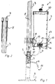
- FIG. 1 shows a cleaning device 1, which is provided for cleaning the bottom surface and for applying a disinfecting liquid.
- the cleaning device 1 has a plate-shaped distributor surface 2, which is only indicated by the dot-dash line and is held at the bottom end of a handling handle 3.
- a reservoir 4 is arranged, which serves for storing the cleaning or disinfecting liquid.
- a dispensing member 5 is integrated, which is interposed in an outlet conduit 6.
- the dispensing member 5 is operable with a handle 7 shown in more detail in Fig. 2, which is movable on the stem 3 between a dispensing position and a closed position shown here.
- the handle 7 is here as, formed in the distributor surface 2 remote from the handle opening displaceably guided push button.
- the thus arranged in the grip region of the handling handle 3 and connected via an actuating link 8 to the dispensing member 5 handle 7 is movable from a closed position against the restoring force of a return spring 9 in a dispensing position.
- the dispensing member 5 is formed here as a valve which remains in its dispensing or open position during depression of the handle 7.
- the disinfecting liquid can pass the valve cone 10 moved out of its valve seat - In a downstream of the discharge member 5 downstream portion of the outlet conduit 6 to flow.
- This portion of the outlet line 6 has an outlet opening 11, which opens outside of the plate-shaped distributor surface 2 in front of a broad side of the distributor surface 2.
- the reservoir 4 of the cleaning device 1 according to the invention is designed as a pressure vessel, which can be offset by means of a hand pump not shown here under pressure. If the dispensing element 5 interposed in the outlet line 6 of the storage container 4 is moved by means of the handle 7 from its closed position into the dispensing position, the cleaning or disinfecting liquid is expelled from the storage container 4 by the overpressure in the container interior. In this case, the cleaning or disinfecting liquid can also be easily and conveniently expelled from the reservoir 4, if the cleaning device according to the invention, for example, when cleaning and disinfecting large-area wall areas in approximately horizontal position or even over the head must be used. In this case, only the dispensing member 5 must be kept in its dispensing position without at the same time constantly perform pumping movements on a liquid pump during the cleaning process.
- the pressure pump required for pressurizing the reservoir can - be arranged separately from the cleaning device 1 - as here.
- an embodiment in which the pressure pump is integrated into the cleaning device 1 is particularly advantageous and easy to handle.
- the clear passage cross-section of the drain line 6 or the discharge member 5 is so dimensioned at least in a section that even when the dispensing member is open only a metered amount of liquid flow through and can escape.
- Fig. 1 it can be seen that the reservoir 4, in a container holder 12 is releasably held, which in turn is attached to the stem 3.
- the reservoir 4 is frontally inserted into the cup-shaped container holder 12.
- a self-closing in the removal of the reservoir 4 valve is provided, which opens into the connected to the container holder 12 outlet conduit 6.
- the container holder 12 has a passage cannula 13, which can penetrate a passage skin 14 provided on the front side of the reservoir 4 which can be inserted into the container holder 12 and serves as a container closure.
- This passage skin 14 has a cross-shaped slit, which is opened upon insertion of the cannula 13 and, when the cannula 13 is pulled out, is resealed tightly by the inherent elasticity of the material used for the passage skin 14.
- the reservoir 4 is detachably connectable to the container holder 12 by means of a Renktagen.
- a Renktagen For this purpose, on two opposite sides of two mounting pins 15 on the front inside of the container holder 12, which have an undercut and cooperate with an associated bayonet opening 16.
- These bayonet openings 16 are provided on the portion of an annular connecting element 17 projecting beyond the storage container 4, which in turn communicates with the storage container 4 is releasably connectable.
- the connecting member 17 is made of a sufficiently stable material
- the reservoir 4 may be made of a transparent or transparent material.
- an external thread 18 is provided, which cooperates with a corresponding internal thread 19 on the inner circumference of the connecting element 17.
- Fig. 1 it is shown that the reservoir 4 is open at its end remote from the container holder 12 front end and releasably closed by means of a container lid 20.
- the container lid 20 carries a ventilation valve 21 which is movable between an open and a closed position.
- FIG. 3 shows a cleaning device in the region of its reservoir 4. Also, the reservoir 4 is frontally inserted into a cup-shaped container holder 12 and has a upon removal of the reservoir automatically occluding valve 13, which opens into the associated with the container holder outlet 6.
- the valve 13 is designed here as a ball valve, the valve ball 22 is guided in a projecting into the container interior ball cage 23.
- a valve lifter 24 On the container holder 12 is a valve lifter 24 which moves the valve ball 22 from its closed position against the force of a return spring 25 in its open position upon insertion of the reservoir 4 in the container holder 12.
- the cannula-like valve lifter 24 has at its free end a passage 26 connected to the outlet conduit 6, through which the cleaning or disinfecting fluid can flow.
- the in the Container holder 12 inserted reservoir 4 is characterized otherwise tightly connected to the outlet conduit 6.
- the handle 3 of the cleaning devices 1 shown here can be composed of at least two detachably connectable handle parts or formed as a telescopic handle.
- the cleaning device shown here is characterized by its particularly simple and convenient handling.
Landscapes
- Apparatus For Disinfection Or Sterilisation (AREA)
- Filters For Electric Vacuum Cleaners (AREA)
- Cleaning In General (AREA)
Abstract
Description
Die Erfindung betrifft ein Reinigungsgerät mit einer Verteilerfläche zum flächigen Verteilen einer Reinigungs- oder Desinfektionsflüssigkeit, welche Verteilerfläche mit einem rohrförmigen Stiel verbunden ist, mit einem Vorratsbehälter zum Bevorraten der Reinigungs- oder Desinfektionsflüssigkeit, sowie mit einem Abgabeorgan, das in eine mit dem Vorratsbehälter verbundene Auslaßleitung zwischengeschaltet und mit einer Handhabe betätigbar ist, welche Handhabe als ein am Stiel zwischen einer Abgabestellung und einer Schließstellung des Abgabeorgans bewegbares Betätigungselement ausgebildet ist.The invention relates to a cleaning device having a distributor surface for distributing a surface of a cleaning or disinfecting liquid, which distributor surface is connected to a tubular handle, with a reservoir for storing the cleaning or disinfecting liquid, as well as with a dispensing member which is connected to an outlet line connected to the reservoir interposed and can be actuated with a handle, which handle is designed as a movable on the stem between a dispensing position and a closed position of the dispensing member actuator.
Man kennt bereits ein Desinfektionsgerät, das ähnlich wie ein Bodenwischer oder ein Reinigungsmop ausgebildet ist. Das vorbekannte Desihfektionsgerät hat einen Handhabungsstiel, der an seinem bodenseitigen Stielende eine plattenförmige Verteilerfläche in der Art eines Mophalters trägt. An dem Stiel ist ein Vorratsbehälter gehalten, in welchem eine Desinfektionsflüssigkeit bevorratet werden kann. Dieser Vorratsbehälter hat einen nach vorne vorstehenden Flüssigkeitsauslaß sowie eine Flüssigkeitspumpe, so daß mit jeder Betätigung der Pumpe eine vorbestimmte Menge des Desinfektionsmittels auf den Boden abgegeben und anschließend mittels der Verteilerfläche verteilt werden kann. Solche Desinfektionsgeräte werden von den Reinigungskräften beispielsweise in Krankenhäusern benötigt, um dort den Boden zu reinigen und zu desinfizieren.One already knows a disinfection device that is similar to a floor wiper or a cleaning mop. The known Desihfektionsgerät has a handling handle, which carries at its bottom end of the handle plate-shaped distribution surface in the manner of a mop holder. On the stem a storage container is held, in which a disinfecting liquid can be stored. This Reservoir has a forwardly projecting liquid outlet and a liquid pump, so that with each actuation of the pump, a predetermined amount of the disinfectant can be discharged to the ground and then distributed by means of the distributor surface. Such disinfection equipment is needed by the cleaning staff, for example in hospitals, to clean and disinfect the soil there.
Die Handhabung des vorbekannten Desinfektionsgerätes ist vergleichsweise mühsam. Da die Reinigungskräfte nämlich mehrere Stunden zum Reinigen großer Bodenflächen benötigen, und da die Bedienung des Vorratsbehälters stets die Betätigung der Flüssigkeitspumpe erfordert, müssen die Reinigungskräfte über Stunden ständig die Flüssigkeitspumpe bedienen.The handling of the prior art disinfection device is relatively cumbersome. Namely, since the cleaners require several hours to clean large floor areas, and since the operation of the storage tank always requires the operation of the liquid pump, the cleaners must constantly operate the liquid pump for hours.
Aus der DE 29 32 110 A1 ist ein Reinigungsgerät der eingangs erwähnten Art bekannt, bei welchem das in die Auslaßleitung des Vorratsbehälters zwischengeschaltete Abgabeorgan mit Hilfe einer Handhabe betätigbar ist, welche Handhabe als ein am Stiel zwischen einer Abgabestellung und einer Schließstellung des Abgabeorgans bewegbares Betätigungselement ausgebildet ist. Dabei ist das Abgabeorgan lediglich als ein Durchlaßventil ausgestaltet, das in seiner Abgabestellung den lichten Leitungsquerschnitt der Auslaßleitung freigibt und in seiner Schließstellung diesen Leitungsquerschnitt sperrt.From DE 29 32 110 A1 a cleaning device of the type mentioned is known, in which the interposed in the outlet of the reservoir discharge member is actuated by means of a handle, which handle designed as a stem movable between a dispensing position and a closed position of the dispensing member movable actuator is. In this case, the dispensing member is configured only as a passage valve, which releases the clear line cross-section of the outlet in its delivery position and blocks this line cross-section in its closed position.
Mit Hilfe des aus DE 29 32 110 A1 vorbekannten Reinigungsgerätes kann eine Reinigungs- oder Desinfektionsflüssigkeit großflächig auf den Boden oder auch eine Wandfläche aufgebracht werden. Da der Vorratsbehälter oberhalb der Auslaßöffnung am Stiel des Reinigungsgerätes angeordnet ist, kann eine Reinigungs- oder Desinfektionsflüssigkeit schwerkraftbedingt aus dem Vorratsbehälter fließen, wenn das Abgabeorgan in seine Abgabestellung bewegt wird. Allerdings ist beim Reinigen insbesondere von Wandflächen auf die Lage des Gerätestieles und die Anordnung des Vorratsbehälters oberhalb der Auslaßöffnung zu achten, um die Funktionsfähigkeit des vorbekannten Reinigungsgerätes stets zu gewährleisten.With the aid of the previously known from DE 29 32 110 A1 cleaning device, a cleaning or disinfecting liquid can be applied over a large area on the floor or a wall surface. Since the reservoir is located above the outlet opening on the handle of the cleaning device, a cleaning or disinfecting fluid can flow from the reservoir due to gravity, when the delivery member in his delivery position is moved. However, when cleaning in particular of wall surfaces on the position of the device handle and the arrangement of the reservoir above the outlet to pay attention to ensure the functionality of the prior art cleaning device always.
Weitere Ausgestaltungen eines solchen Reinigungsgerätes sind aus EP 0 997 099 A2 sowie aus der DE 39 05 760 A1 bekannt. Diese Vorrichtungen unterscheiden sich in ihrer Handhabung jedoch nicht von dem aus DE 29 32 110 A1 vorbekannten Reinigungsgerät.Further embodiments of such a cleaning device are known from EP 0 997 099 A2 and from DE 39 05 760 A1. However, these devices do not differ in their handling from the previously known from DE 29 32 110 A1 cleaning device.
Es besteht daher die Aufgabe, ein Reinigungsgerät der eingangs erwähnten Art zu schaffen, mit welchem sich sowohl Boden- als auch Wandflächen einfach und bequem reinigen oder desinfizieren lassen, ohne daß ständig Pumpbewegungen an einer manuellen Flüssigkeitspumpe durchzuführen sind.It is therefore an object to provide a cleaning device of the type mentioned, with which both floor and wall surfaces can be easily and conveniently cleaned or disinfected without constantly pumping movements are performed on a manual fluid pump.
Die erfindungsgemäße Lösung dieser Aufgabe besteht bei dem Reinigungsgerät der eingangs erwähnten Art insbesondere darin, daß der Vorratsbehälter als Druckbehälter ausgebildet ist, der mittels einer Druckpumpe unter Überdruck versetzbar ist.The inventive solution to this problem is in the cleaning device of the type mentioned in particular that the reservoir is designed as a pressure vessel, which is displaceable by means of a pressure pump under pressure.
Der Vorratsbehälter des erfindungsgemäßen Reinigungsgerätes ist als Druckbehälter ausgebildet, der mittels einer Handpumpe unter Überdruck versetzt werden kann. Wird das in die Auslaßleitung des Vorratsbehälters zwischengeschaltete Abgabeorgan mittels der Handhabe von seiner Schließstellung in die Abgabestellung bewegt, wird die Reinigungs- oder Desinfektionsflüssigkeit durch den Überdruck im Behälterinneren aus dem Vorratsbehälter ausgetrieben. Dabei kann die Reinigungs- oder Desinfektionsflüssigkeit auch dann noch einfach und bequem aus dem Vorratsbehälter ausgetrieben werden, wenn das erfindungsgemäße Reinigungsgerät beispielsweise beim Reinigen und Desinfizieren großflächiger Wandbereiche in etwa horizontaler Lage oder gar über Kopf eingesetzt werden muß. Dabei muß lediglich das Abgabeorgan in seiner Abgabestellung gehalten werden, ohne daß gleichzeitig während des Reinigungsvorganges ständig Pumpbewegungen an einer Flüssigkeitspumpe durchzuführen sind.The reservoir of the cleaning device according to the invention is designed as a pressure vessel, which can be offset by means of a hand pump under pressure. If the dispensing member interposed in the outlet line of the storage container is moved by means of the handle from its closed position to the dispensing position, the cleaning or disinfecting liquid is expelled from the storage container by the overpressure in the container interior. The cleaning or disinfecting liquid can then also be easily and conveniently expelled from the reservoir, though For example, the cleaning device according to the invention must be used in cleaning and disinfecting large-area wall areas in an approximately horizontal position or even overhead. In this case, only the dispensing member must be kept in its dispensing position, without at the same time constantly perform pumping movements to a liquid pump during the cleaning process.
Die Druckpumpe des erfindungsgemäßen Reinigungsgerätes kann eine elektrische Motorpumpe oder zumindest eine Gaspatrone als Druckquelle aufweisen. Bevorzugt wird jedoch eine Ausführungsform, bei der die Druckpumpe als Handpumpe ausgestaltet ist.The pressure pump of the cleaning device according to the invention may have an electric motor pump or at least a gas cartridge as a pressure source. However, an embodiment in which the pressure pump is designed as a hand pump is preferred.
Die Druckpumpe kann gegebenenfalls auch mehreren Reinigungsgeräten zugeordnet und dazu extern angeordnet sein. Möglich ist auch, daß die Druckpumpe auf den Vorratsbehälter aufgesetzt ist. Bevorzugt wird jedoch eine Ausführungsform, bei der die Druckpumpe in das Reinigungsgerät integriert ist.If appropriate, the pressure pump can also be assigned to a plurality of cleaning devices and arranged externally for this purpose. It is also possible that the pressure pump is placed on the reservoir. However, an embodiment in which the pressure pump is integrated into the cleaning device is preferred.
Um die einfache Handhabung des erfindungsgemäßen Reinigungsgerätes noch zusätzlich zu erleichtern, ist es zweckmäßig, wenn die Handhabe von einer Schließstellung gegen eine Rückstellkraft in eine Abgabestellung bewegbar ist.In order to facilitate the simple handling of the cleaning device according to the invention in addition, it is expedient if the handle is movable from a closed position against a restoring force in a dispensing position.
Damit das erfindungsgemäße Reinigungsgerät sicher gehalten und rasch über die Bodenfläche bewegt werden kann, während gleichzeitig das Abgabeorgan des Reinigungsgerätes betätigt wird, ist es vorteilhaft, wenn die Handhabe im Haltebereich des Stieles angeordnet ist.Thus, the cleaning device according to the invention can be held securely and quickly moved over the bottom surface, while the dispensing member of the cleaning device is operated, it is advantageous if the handle is arranged in the holding region of the stem.
Die Handhabe kann als ein den Stiel umgreifender Haltering ausgebildet sein, der am Stiel beweglich geführt ist. Möglich ist aber auch, daß die Handhabe als ein am Stiel verschwenkbar gehaltener Betätigungshebel ausgebildet ist. Bevorzugt wird jedoch eine Ausführungsform, bei der vorgesehen ist, daß die Handhabe als ein in der der Verteilerfläche abgewandten Stielöffnung verschieblich geführter Druckknopf ausgebildet ist.The handle may be formed as a handle surrounding the handle retaining ring, which is movably guided on the handle. Possible but is also that the handle is designed as a handle pivotally held on the handle. However, preference is given to an embodiment in which it is provided that the handle is formed as a pushbutton displaceably guided in the handle opening facing away from the distributor surface.
Vorteilhaft ist es, wenn das Abgabeorgan im Rohrinneren des Stiels angeordnet und über ein Betätigungsgestänge mit der Handhabe verbunden ist.It is advantageous if the dispensing member is arranged in the interior of the tube of the stem and connected via an actuating linkage with the handle.
Das Abgabeorgan kann beispielsweise als Flüssigkeitspumpe ausgebildet sein, die insbesondere manuell durch Pumpbewegungen des Reinigungspersonals betätigt wird. Um das Reinigungspersonal während des Aufwischens des Bodens nicht zusätzlich mit Pumpbewegungen an einem als Flüssigkeitspumpe ausgebildeten Abgabeorgan zu belasten, sieht ein weiterer Vorschlag gemäß der Erfindung von eigener schutzwürdiger Bedeutung vor, daß das Abgabeorgan als Ventil ausgestaltet ist.The dispensing member may be formed, for example, as a liquid pump, which is in particular operated manually by pumping movements of the cleaning staff. In order not to burden the cleaning personnel during the wiping of the soil in addition with pumping movements on a designed as a liquid pump delivery member, provides a further proposal according to the invention of its own worth-worthy importance that the delivery member is designed as a valve.
Damit die Reinigungs- oder Desinfektionsflüssigkeit an beliebiger Stelle auf den Boden aufgetragen und anschließend gezielt mit der Verteilerfläche des Reinigungsgerätes verteilt werden kann, sieht eine bevorzugte Ausführungsform gemäß der Erfindung vor, daß der dem Abgabeorgan abströmseitig nachgeschaltete Teilbereich der Auslaßleitung eine Auslaßöffnung hat, die vor oder hinter einer Breitseite der Verteilerfläche mündet.So that the cleaning or disinfecting liquid can be applied anywhere on the floor and then selectively distributed with the distributor surface of the cleaning device, a preferred embodiment according to the invention that the discharge member downstream the downstream portion of the outlet conduit has an outlet opening before or opens behind a broad side of the distributor surface.
Damit der Vorratsbehälter bequem aufgefüllt werden kann und damit stets mehrere Vorratsbehälter in gefülltem Zustand bereitgehalten werden können, sieht ein weiterer Vorschlag gemäß der Erfindung, für den selbständig Schutz beansprucht wird, vor, daß der Vorratsbehälter in einer Behälterhalterung lösbar gehalten ist, welche Behälterhalterung mit dem Stiel verbunden ist.So that the reservoir can be filled up easily and thus always several reservoirs can be kept in a filled state, provides a further proposal according to the invention, is claimed for the self-protection, before, that the reservoir in a container holder is releasably held, which container holder is connected to the stem.
Um den Vorratsbehälter rasch in der Behälterhalterung montieren und an die Auslaßleitung anschließen zu können, ist es vorteilhaft, wenn der Vorratsbehälter stirnseitig in eine topfförmige Behälterhalterung einsetzbar ist und wenn zwischen der Behälterhalterung und dem Vorratsbehälter ein bei Entnahme des Vorratsbehälters vorzugsweise selbsttätig verschließendes Ventil vorgesehen ist, welches in der mit der Behälterhalterung verbundenen Auslaßleitung mündet.In order to quickly mount the reservoir in the container holder and to connect to the outlet, it is advantageous if the reservoir is used frontally in a cup-shaped container holder and if between the container holder and the reservoir is provided on removal of the reservoir preferably automatically closing valve, which opens into the outlet pipe connected to the outlet.
Eine bevorzugte Weiterbildung gemäß der Erfindung sieht dazu vor, daß das Ventil als Kugelventil ausgestaltet ist, dessen Ventilkugel beim Einsetzen des Vorratsbehälters mittels eines an der Behälterhalterung vorgesehenen Ventilhebers gegen eine Rückstellkraft von einer Schließstellung in eine Offenstellung bewegbar ist, und daß der Ventilheber zumindest eine mit der Auslaßleitung verbundene Durchtrittsöffnung hat.A preferred development according to the invention provides that the valve is designed as a ball valve whose valve ball is movable upon insertion of the reservoir by means of a provided on the container holder valve lifter against a restoring force from a closed position to an open position, and that the valve lifter with at least one the outlet conduit has connected passage opening.
Nach einem anderen Vorschlag gemäß der Erfindung ist vorgesehen, daß die Behälterhalterung eine mit der Auslaßleitung verbundene Durchstech- oder Durchtrittskanüle hat und daß an der in die Behälterhalterung einsetzbaren Stirnseite des Vorratsbehälters eine mit der Durchstech- oder Durchtrittskanüle durchstechbare oder durchdringbare Durchstech- oder Durchtrittshaut vorgesehen ist. Der als Durchstechhaut ausgebildete Behälterverschluß kann mittels der Durchstechkanüle geöffnet werden. Möglich ist aber auch, daß die Durchtrittshaut bereits eine kreuz- oder schlitzförmige Durchtrittsöffnung aufweist, die beim Einführen der Durchtrittskanüle geöffnet und aufgrund der Elastizität des für die Durchtrittshaut verwendeten Materials beim Herausziehen der Kanüle selbsttätig wieder verschlossen wird.According to another proposal according to the invention it is provided that the container holder has a connected to the outlet line piercing or passage cannula and that on the insertable into the container holder end face of the reservoir is provided with a pierceable or penetrating pierceable or penetrable puncture or penetration skin , The container closure formed as a puncture skin can be opened by means of the piercing cannula. However, it is also possible that the passage skin already has a cross-shaped or slot-shaped passage opening, which is opened upon insertion of the passage cannula and automatically closed again on withdrawal of the cannula due to the elasticity of the material used for the passage skin.
Um die Handhabung des erfindungsgemäßen Reinigungsgerätes zu erleichtern, ist es vorteilhaft, wenn der Vorratsbehälter in der Behälterhalterung lösbar sicherbar ist. Dabei sieht eine bevorzugte Ausführungsform gemäß der Erfindung vor, daß der Vorratsbehälter mit der Behälterhalterung mittels einer Schraub- oder Renkverbindung lösbar verbindbar ist.In order to facilitate the handling of the cleaning device according to the invention, it is advantageous if the reservoir is detachably securable in the container holder. In this case, a preferred embodiment according to the invention provides that the storage container with the container holder by means of a screw or Renkverbindung is detachably connectable.
So kann beispielsweise in der Stirninnenseite der Behälterhalterung zumindest ein eine Hinterschneidung aufweisender Befestigungszapfen vorgesehen sein, der zum Verbinden mit dem Vorratsbehälter mit einer zugeordneten Bajonettöffnung zusammenwirkt.Thus, for example, at least one fastening lug having an undercut can be provided in the front inside of the container holder which cooperates with an associated bayonet opening for connection to the reservoir.
Vorteilhaft ist es, wenn der Vorratsbehälter mit einem ringförmigen Verbindungselement lösbar verbindbar ist, das in einem über den Vorratsbehälter überstehenden Teilbereich zumindest eine Bajonettöffnung hat. Bei dieser Ausführungsform können der Vorratsbehälter und das Verbindungselement aus unterschiedlichen Materialien hergestellt werden; so ist es beispielsweise möglich, das Verbindungselement aus einem hochbelastbaren Kunststoffmaterial herzustellen, während der Vorratsbehälter aus einem durchsichtigen oder transparenten Material hergestellt ist.It is advantageous if the storage container can be detachably connected to an annular connecting element which has at least one bayonet opening in a partial region projecting beyond the storage container. In this embodiment, the reservoir and the connecting element can be made of different materials; For example, it is possible to produce the connecting element from a highly resilient plastic material, while the reservoir is made of a transparent or transparent material.
Um den Vorratsbehälter, das Verbindungselement sowie die am Reinigungsgerät montierte Behälterhalterung zu einer Funktionseinheit zusammenfügen zu können, ist es vorteilhaft, wenn der Vorratsbehälter und das Verbindungselement lösbar verbindbar sind und wenn dazu am Behälterumfang des zylinderförmigen Vorratsbehälters ein Außengewinde vorgesehen ist, welches mit einem Innengewinde am Innenumfang des Verbindungselementes zusammenwirkt.In order to assemble the reservoir, the connecting element and the mounted on the cleaning device holder to a functional unit, it is advantageous if the reservoir and the connecting element are detachably connectable and if to the container circumference of the cylindrical reservoir, an external thread is provided, which with an internal thread on Inner circumference of the connecting element cooperates.
Zum Wiederauffüllen des Vorratsbehälters ist es zweckmäßig, wenn der Vorratsbehälter an seinem der Behälterhalterung abgewandten Stirnende offen ausgebildet und mittels eines Behälterdeckels vorzugsweise lösbar verschließbar ist.For refilling the storage container, it is expedient if the storage container is designed to be open at its end remote from the container holder and preferably releasably closable by means of a container lid.
Um die Entnahme und Abgabe der Reinigungs- oder Desinfektionsflüssigkeit aus dem Vorratsbehälter zu erleichtern, ist es vorteilhaft, wenn der Behälterdeckel ein vorzugsweise zwischen einer Offenstellung und einer Schließstellung bewegbares Belüftungsventil trägt.In order to facilitate the removal and delivery of the cleaning or disinfecting liquid from the storage container, it is advantageous if the container lid carries a preferably movable between an open position and a closed position ventilation valve.
Vorteilhaft ist es, wenn der Vorratsbehälter oberhalb der Auslaßleitung und des zwischengeschalteten Abgabeorgans angeordnet ist. Bei einer solchen Ausführungsform kann die Reinigungs- oder Desinfektionsflüssigkeit bei geöffnetem Abgabeventil infolge der Schwerkraft auch dann noch ohne weiteres aus der Auslaßleitung ausfließen, wenn der Vorratsbehälter vorübergehend nicht unter Überdruck steht.It is advantageous if the storage container is arranged above the outlet line and the intermediate dispensing member. In such an embodiment, the cleaning or disinfecting liquid with open dispensing valve due to gravity even then easily flow out of the outlet if the reservoir is temporarily not under pressure.
Weitere Merkmale der Erfindung-ergeben sich aus der folgenden Beschreibung eines erfindungsgemäßen Ausführungsbeispieles in Verbindung mit den Ansprüchen sowie der Zeichnung. Die einzelnen Merkmale können je für sich oder zu mehreren bei einer Ausführungsform gemäß der Erfindung verwirklicht sein.Further features of the invention will become apparent from the following description of an embodiment of the invention in conjunction with the claims and the drawings. The individual features may be implemented individually or in combination in an embodiment according to the invention.
Es zeigt:
- Fig. 1
- ein Reinigungsgerät in einem Längsschnitt im Bereich eines zum Bevorraten einer Reinigungs- oder Desinfektionsflüssigkeit vorgesehenen Vorratsbehälters,
- Fig. 2
- das Reinigungsgerät aus Figur 1 in einem weiteren Längsschnitt im Bereich eines am Stirnende eines Handhabungsstiels vorgesehenen Druckknopfes, und
- Fig. 3
- ein Reinigungsgerät, ähnlich dem aus den Figuren 1 und 2, im Bereich seines Vorratsbehälters.
- Fig. 1
- a cleaning device in a longitudinal section in the region of a reservoir provided for storing a cleaning or disinfecting liquid,
- Fig. 2
- the cleaning device of Figure 1 in a further longitudinal section in the region of a provided at the front end of a handling handle push button, and
- Fig. 3
- a cleaning device, similar to that of Figures 1 and 2, in the region of its reservoir.
In Figur 1 ist ein Reinigungsgerät 1 dargestellt, das zum Reinigen der Bodenfläche und zum Auftragen einer Desinfektionsflüssigkeit vorgesehen ist. Das Reinigungsgerät 1 hat eine hier nur strichpunktiert angedeutete plattenförmige Verteilerfläche 2, die am bodenseitigen Ende eines Handhabungsstieles 3 gehalten ist. Am Stiel 3 ist ein Vorratsbehälter 4 angeordnet, der zum Bevorraten der Reinigungs- oder Desinfektionsflüssigkeit dient. Im Rohrinneren des rohrförmigen Stieles 4 ist ein Abgabeorgan 5 integriert, das in einer Auslaßleitung 6 zwischengeschaltet ist. Das Abgabeorgan 5 ist mit einer in Fig. 2 näher dargestellten Handhabe 7 betätigbar, die am Stiel 3 zwischen einer Abgabestellung und einer hier gezeigten Schließstellung bewegbar ist.FIG. 1 shows a cleaning device 1, which is provided for cleaning the bottom surface and for applying a disinfecting liquid. The cleaning device 1 has a plate-shaped
Die Handhabe 7 ist hier als, ein in der der Verteilerfläche 2 abgewandten Stielöffnung verschieblich geführter Druckknopf ausgebildet. Die somit im Griffbereich des Handhabungsstieles 3 angeordnete und über ein Betätigungsgestänge 8 mit dem Abgabeorgan 5 verbundene Handhabe 7 ist von einer Schließstellung gegen die Rückstellkraft einer Rückstellfeder 9 in eine Abgabestellung bewegbar.The handle 7 is here as, formed in the
Aus Fig. 1 wird deutlich, daß das Abgabeorgan 5 hier als Ventil ausgebildet ist, das während des Niederdrückens der Handhabe 7 in seiner Abgabe- oder Offenstellung verbleibt. In der Offenstellung des Ventils 5 kann die Desinfektionsflüssigkeit - an dem aus seinem Ventilsitz bewegten Ventilkegel 10 vorbei - in einen dem Abgabeorgan 5 abströmseitig nachgeschalteten Teilbereich der Auslaßleitung 6 einströmen. Dieser Teilbereich der Auslaßleitung 6 hat eine Auslaßöffnung 11, die außerhalb der plattenförmigen Verteilerfläche 2 vor einer Breitseite der Verteilerfläche 2 mündet. Durch Betätigen des Druckknopfes 7 wird das Abgabeorgan 5 derart geöffnet, daß die Desinfektionsflüssigkeit ausfließen und gezielt auf dem Boden aufgetragen werden kann, um sie anschließend auf der Bodenfläche flächig zu verteilen.From Fig. 1 it is clear that the dispensing
Dabei ist der Vorratsbehälter 4 des erfindungsgemäßen Reinigungsgerätes 1 als Druckbehälter ausgebildet, der mittels einer hier nicht weiter dargestellten Handpumpe unter Überdruck versetzt werden kann. Wird das in die Auslaßleitung 6 des Vorratsbehälters 4 zwischengeschaltete Abgabeorgan 5 mittels der Handhabe 7 von seiner Schließstellung in die Abgabestellung bewegt, wird die Reinigungs- oder Desinfektionsflüssigkeit durch den Überdruck im Behälterinneren aus dem Vorratsbehälter 4 ausgetrieben. Dabei kann die Reinigungs- oder Desinfektionsflüssigkeit auch dann noch einfach und bequem aus dem Vorratsbehälter 4 ausgetrieben werden, wenn das erfindungsgemäße Reinigungsgerät beispielsweise beim Reinigen und Desinfizieren großflächiger Wandbereiche in etwa horizontaler Lage oder gar über Kopf eingesetzt werden muß. Dabei muß lediglich das Abgabeorgan 5 in seiner Abgabestellung gehalten werden, ohne daß gleichzeitig während des Reinigungsvorganges ständig Pumpbewegungen an einer Flüssigkeitspumpe durchzuführen sind.In this case, the reservoir 4 of the cleaning device 1 according to the invention is designed as a pressure vessel, which can be offset by means of a hand pump not shown here under pressure. If the dispensing
Die zur Druckbeaufschlagung des Vorratsbehälters erforderliche Druckpumpe kann - wie hier - separat vom Reinigungsgerät 1 angeordnet sein. Besonders vorteilhaft und leicht zu handhaben ist jedoch eine Ausführungsform, bei welcher die Druckpumpe in das Reinigungsgerät 1 integriert ist.The pressure pump required for pressurizing the reservoir can - be arranged separately from the cleaning device 1 - as here. However, an embodiment in which the pressure pump is integrated into the cleaning device 1 is particularly advantageous and easy to handle.
Der lichte Durchtrittsquerschnitt der Abflußleitung 6 oder des Abgabeorgans 5 ist zumindest in einem Teilabschnitt so bemessen, daß auch bei geöffnetem Abgabeorgan nur eine dosierte Flüssigkeitsmenge durchfließen und austreten kann.The clear passage cross-section of the
In Fig. 1 ist erkennbar, daß der Vorratsbehälter 4, in einer Behälterhalterung 12 lösbar gehalten ist, die ihrerseits am Stiel 3 befestigt ist. Der Vorratsbehälter 4 ist stirnseitig in die topfförmige Behälterhalterung 12 einsetzbar. Zwischen der Behälterhalterung 12 und dem Vorratsbehälter 4 ist ein bei der Entnahme des Vorratsbehälters 4 selbsttätig verschließendes Ventil vorgesehen, welches in der mit der Behälterhalterung 12 verbundenen Auslaßleitung 6 mündet.In Fig. 1 it can be seen that the reservoir 4, in a
Die Behälterhalterung 12 weist dazu eine Durchtrittskanüle 13 auf, die eine an der in die Behälterhalterung 12 einsetzbaren Stirnseite des Vorratsbehälter 4 vorgesehene und als Behälterverschluß dienende Durchtrittshaut 14 durchdringen kann. Diese Durchtrittshaut 14 weist einen kreuzförmigen Schlitz auf, der beim Einführen der Kanüle 13 geöffnet und beim Herausziehen der Kanüle 13 durch die Eigenelastizität des für die Durchtrittshaut 14 verwendeten Materials wieder dicht verschlossen wird.For this purpose, the
Der Vorratsbehälter 4 ist mit der Behälterhalterung 12 mittels einer Renkverbindung lösbar verbindbar. Dazu stehen auf gegenüberliegenden Seiten zwei Befestigungszapfen 15 über die Stirninnenseite der Behälterhalterung 12 vor, die eine Hinterschneidung aufweisen und mit einer zugeordneten Bajonettöffnung 16 zusammenwirken.
Diese Bajonettöffnungen 16 sind an dem über den Vorratsbehälter 4 überstehenden Teilbereich eines ringförmigen Verbindungselementes 17, vorgesehen, das seinerseits mit dem Vorratsbehälter 4 lösbar verbindbar ist. Während das Verbindungselement 17 aus einem ausreichend stabilen Material hergestellt ist, kann der Vorratsbehälter 4 aus einem transparenten oder durchsichtigen Material bestehen.The reservoir 4 is detachably connectable to the
These
Am Behälterumfang des zylinderförmigen Vorratsbehälters 4 ist ein Außengewinde 18 vorgesehen, welches mit einem korrespondierenden Innengewinde 19 am Innenumfang des Verbindungselementes 17 zusammenwirkt.At the container circumference of the cylindrical reservoir 4, an
In Fig. 1 ist gezeigt, daß der Vorratsbehälter 4 an seinem der Behälterhalterung 12 abgewandten Stirnende offen ausgebildet und mittels eines Behälterdeckels 20 lösbar verschließbar ist. Der Behälterdeckel 20 trägt ein Belüftungsventil 21, das zwischen einer Offen- und einer Schließstellung bewegbar ist.In Fig. 1 it is shown that the reservoir 4 is open at its end remote from the
In Figur 3 ist ein Reinigungsgerät im Bereich seines Vorratsbehälters 4 dargestellt. Auch der Vorratsbehälter 4 ist stirnseitig in eine topfförmige Behälterhalterung 12 einsetzbar und weist ein bei Entnahme des Vorratsbehälters selbsttätig verschließendes Ventil 13 auf, welches in der mit der Behälterhalterung verbundenen Auslaßleitung 6 mündet.FIG. 3 shows a cleaning device in the region of its reservoir 4. Also, the reservoir 4 is frontally inserted into a cup-shaped
Das Ventil 13 ist hier als Kugelventil ausgestaltet, dessen Ventilkugel 22 in einem in das Behälterinnere vorstehende Kugelkäfig 23 geführt ist. An der Behälterhalterung 12 steht ein Ventilheber 24 vor, der beim Einsetzen des Vorratsbehälters 4 in die Behälterhalterung 12 die Ventilkugel 22 von ihrer Schließstellung gegen die Kraft einer Rückstellfeder 25 in ihre Offenstellung bewegt. Der kanülenartige Ventilheber 24 weist an seinem freien Ende eine mit der Auslaßleitung 6 verbundene Durchtrittsöffnung 26 auf, durch welche die Reinigungs- oder Desinfektionsflüssigkeit fließen kann. Der in die Behälterhalterung 12 eingesetzte Vorratsbehälter 4 ist dadurch ansonsten dicht mit der Auslaßleitung 6 verbunden.The
Es versteht sich, daß der Stiel 3 der hier dargestellten Reinigungsgeräte 1 aus zumindest zwei lösbar miteinander verbindbaren Stielteilen zusammengesetzt oder als Teleskopstiel ausgebildet sein kann.It is understood that the
Da der Vorratsbehälter 4 der in den Figuren 1 und 2 einerseits und Figur 3 andererseits gezeigten Reinigungsgeräte 1 oberhalb der Auslaßleitung 6 und des zwischengeschalteten Abgabeorgans 5 angeordnet ist, kann die Reinigungs- oder Desinfektionsflüssigkeit bei geöffnetem Abgabeorgan 5 auch dann noch allein schwerkraftbedingt aus der Auslaßöffnung 11 der Auslaßleitung 6 ausfließen, selbst wenn der Vorratsbehälter 4 vorübergehend nicht unter Überdruck steht.Since the reservoir 4 of the cleaning devices 1 shown in Figures 1 and 2 on the one hand and Figure 3 above the
Das hier dargestellte Reinigungsgerät zeichnet sich durch seine besonders einfache und bequeme Handhabung aus.The cleaning device shown here is characterized by its particularly simple and convenient handling.
Claims (22)
Applications Claiming Priority (2)
| Application Number | Priority Date | Filing Date | Title |
|---|---|---|---|
| DE10040014A DE10040014A1 (en) | 2000-08-16 | 2000-08-16 | cleaner |
| EP01119417A EP1180343B2 (en) | 2000-08-16 | 2001-08-11 | Cleaning device |
Related Parent Applications (1)
| Application Number | Title | Priority Date | Filing Date |
|---|---|---|---|
| EP01119417A Division EP1180343B2 (en) | 2000-08-16 | 2001-08-11 | Cleaning device |
Publications (3)
| Publication Number | Publication Date |
|---|---|
| EP1688081A2 true EP1688081A2 (en) | 2006-08-09 |
| EP1688081A3 EP1688081A3 (en) | 2007-07-11 |
| EP1688081B1 EP1688081B1 (en) | 2009-12-23 |
Family
ID=7652612
Family Applications (2)
| Application Number | Title | Priority Date | Filing Date |
|---|---|---|---|
| EP06009407A Expired - Lifetime EP1688081B1 (en) | 2000-08-16 | 2001-08-11 | Cleaning device |
| EP01119417A Expired - Lifetime EP1180343B2 (en) | 2000-08-16 | 2001-08-11 | Cleaning device |
Family Applications After (1)
| Application Number | Title | Priority Date | Filing Date |
|---|---|---|---|
| EP01119417A Expired - Lifetime EP1180343B2 (en) | 2000-08-16 | 2001-08-11 | Cleaning device |
Country Status (3)
| Country | Link |
|---|---|
| EP (2) | EP1688081B1 (en) |
| AT (2) | ATE325572T1 (en) |
| DE (3) | DE10040014A1 (en) |
Cited By (1)
| Publication number | Priority date | Publication date | Assignee | Title |
|---|---|---|---|---|
| DE102015009751A1 (en) | 2015-07-29 | 2017-02-02 | Avet Ag | cleaner |
Families Citing this family (11)
| Publication number | Priority date | Publication date | Assignee | Title |
|---|---|---|---|---|
| EP1553867A2 (en) | 2002-09-09 | 2005-07-20 | The Procter & Gamble Company | Fluid delivery mechanism |
| DE10313114A1 (en) * | 2003-03-24 | 2004-10-07 | Leifheit Ag | Device for cleaning flat surfaces, especially floors, tiled walls and windows, comprises a pump device provided with an adapter for a cleaning fluid tank and arranged in a housing sliding into the lower end of a handle |
| DE102004062336A1 (en) * | 2004-12-20 | 2006-06-29 | Avet Ag | cleaner |
| DE102006009768B3 (en) * | 2006-03-01 | 2007-09-06 | Avet Ag | Applicator for liquid coating agents |
| WO2008005841A2 (en) | 2006-06-30 | 2008-01-10 | Johnsondiversey, Inc. | Closure for a pressurizable container comprising a pump and a vent |
| EP2162368A4 (en) | 2007-06-29 | 2011-06-29 | Diversey Inc | Pressurized dispensable container operable in any orientation |
| DE202010001306U1 (en) | 2010-01-23 | 2010-04-01 | Avet Ag | cleaner |
| DE102010005523B4 (en) | 2010-01-23 | 2023-07-13 | Avet Ag | cleaning device |
| GB2489250A (en) | 2011-03-22 | 2012-09-26 | Avet Ag | Reusable and washable surface cleaning substrate |
| DE102011109132B4 (en) * | 2011-08-01 | 2014-09-25 | Markus Kress | Dispensing device and Ausbringsystem |
| CN105816120B (en) * | 2016-05-19 | 2019-02-12 | 嘉兴捷顺旅游制品有限公司 | A kind of novel mop capable of spraying water |
Citations (4)
| Publication number | Priority date | Publication date | Assignee | Title |
|---|---|---|---|---|
| DE2932110A1 (en) | 1978-08-08 | 1981-02-26 | Hartmut Dietrich | Floor cleaning implement with fluid container - attached to handle, with outlet, conveyor duct and valve |
| DE3905760A1 (en) | 1988-08-16 | 1990-02-22 | Henkel Kgaa | DEVICE FOR TREATING TEXTILE FLOORING |
| BE1007575A6 (en) | 1993-10-06 | 1995-08-08 | Limburgs Schoonmaakbedrijf N V | Universal handle for spraying detergents during cleaning processes |
| EP0997099A2 (en) | 1998-10-26 | 2000-05-03 | A.Z. International S.A. | Mop for cleaning a floor tiling |
Family Cites Families (9)
| Publication number | Priority date | Publication date | Assignee | Title |
|---|---|---|---|---|
| US2053282A (en) * | 1933-12-09 | 1936-09-08 | Johnson & Son Inc S C | Fountain mop |
| US3094152A (en) * | 1962-01-26 | 1963-06-18 | Power Spray Company Inc | Liquid dispensing device for floor machines |
| US3457016A (en) * | 1967-04-25 | 1969-07-22 | Roland C Gotberg | Waxer |
| GB2068720B (en) * | 1980-01-15 | 1983-04-07 | Venrooij W J Van | Cleaning apparatus |
| US4871275A (en) * | 1988-06-28 | 1989-10-03 | Aldous Glenn R | Window washing device |
| FR2735676B1 (en) * | 1995-06-20 | 1997-08-01 | Net System | CLEANING BROOM |
| FR2735679B1 (en) † | 1995-06-23 | 1997-12-05 | Aten Dev | PROCESS FOR PRODUCING A DENTAL PROSTHESIS |
| US5865551A (en) * | 1996-06-10 | 1999-02-02 | New Knight Inc. | Cleaning device with replaceable cleaning fluid reservoir |
| US6142750A (en) * | 1998-11-30 | 2000-11-07 | The Procter & Gamble Company | Gear pump and replaceable reservoir for a fluid sprayer |
-
2000
- 2000-08-16 DE DE10040014A patent/DE10040014A1/en not_active Withdrawn
-
2001
- 2001-08-11 EP EP06009407A patent/EP1688081B1/en not_active Expired - Lifetime
- 2001-08-11 AT AT01119417T patent/ATE325572T1/en active
- 2001-08-11 EP EP01119417A patent/EP1180343B2/en not_active Expired - Lifetime
- 2001-08-11 DE DE50115280T patent/DE50115280D1/en not_active Expired - Lifetime
- 2001-08-11 DE DE50109737T patent/DE50109737D1/en not_active Expired - Lifetime
- 2001-08-11 AT AT06009407T patent/ATE452573T1/en active
Patent Citations (4)
| Publication number | Priority date | Publication date | Assignee | Title |
|---|---|---|---|---|
| DE2932110A1 (en) | 1978-08-08 | 1981-02-26 | Hartmut Dietrich | Floor cleaning implement with fluid container - attached to handle, with outlet, conveyor duct and valve |
| DE3905760A1 (en) | 1988-08-16 | 1990-02-22 | Henkel Kgaa | DEVICE FOR TREATING TEXTILE FLOORING |
| BE1007575A6 (en) | 1993-10-06 | 1995-08-08 | Limburgs Schoonmaakbedrijf N V | Universal handle for spraying detergents during cleaning processes |
| EP0997099A2 (en) | 1998-10-26 | 2000-05-03 | A.Z. International S.A. | Mop for cleaning a floor tiling |
Cited By (3)
| Publication number | Priority date | Publication date | Assignee | Title |
|---|---|---|---|---|
| DE102015009751A1 (en) | 2015-07-29 | 2017-02-02 | Avet Ag | cleaner |
| DE102015009751B4 (en) * | 2015-07-29 | 2019-11-07 | Avet Ag | cleaner |
| US10682036B2 (en) | 2015-07-29 | 2020-06-16 | Avet Ag | Cleaning device |
Also Published As
| Publication number | Publication date |
|---|---|
| EP1688081B1 (en) | 2009-12-23 |
| EP1180343A3 (en) | 2002-10-16 |
| ATE452573T1 (en) | 2010-01-15 |
| DE50115280D1 (en) | 2010-02-04 |
| DE10040014A1 (en) | 2002-03-07 |
| EP1180343A2 (en) | 2002-02-20 |
| DE50109737D1 (en) | 2006-06-14 |
| ATE325572T1 (en) | 2006-06-15 |
| EP1180343B2 (en) | 2009-12-30 |
| EP1688081A3 (en) | 2007-07-11 |
| EP1180343B1 (en) | 2006-05-10 |
Similar Documents
| Publication | Publication Date | Title |
|---|---|---|
| DE102009049261B4 (en) | Wanddosierspender | |
| DE2932110A1 (en) | Floor cleaning implement with fluid container - attached to handle, with outlet, conveyor duct and valve | |
| EP1180343B1 (en) | Cleaning device | |
| DE102006050475B4 (en) | cleaning tank | |
| DE9113987U1 (en) | Washing and cleaning device for the body | |
| EP1451082A1 (en) | Distributing device | |
| DE102019105738A1 (en) | Device with disinfectant dispensing function, in particular for door handles or ironing or bar handles | |
| EP1442692B1 (en) | Toilet brush | |
| DE2051258A1 (en) | Container for receiving and dispensing pressurized care products in the form of cleaning agents and / or lubricants for the care of drivable dental handpieces | |
| DE102009033400A1 (en) | Vaginal shower applicator for vaginal shower-set for personal hygiene, has applicator body extending along longitudinal axis, where applicator body has proximal longitudinal end and distal longitudinal end | |
| DE102006017648B4 (en) | Device for disinfecting a toothbrush head | |
| DE10013495B4 (en) | toilet brush | |
| EP0714253B1 (en) | Dispenser for liquid disinfectants, surfactants and the like | |
| DE102006009768B3 (en) | Applicator for liquid coating agents | |
| DE20014126U1 (en) | Cleaning device | |
| AT403568B (en) | ATTACHMENT OF A DISPENSING HEAD TO A BOTTLE CONTAINING A DISINFECTANT LIQUID, AND INTERMEDIATE PIECE FOR SUCH A FASTENING | |
| DE202019106293U1 (en) | Device for dispensing a liquid containing at least one active substance into a toilet bowl that can be covered with a lid | |
| DE102017002597B3 (en) | toilet brush | |
| CH508386A (en) | Throw away wall mounted soap dispenser | |
| DE3036493C2 (en) | Dispenser for liquid or pasty goods | |
| WO2023222467A1 (en) | Cleaning apparatus | |
| EP0048874A1 (en) | Distributor for liquid or pasty material | |
| WO2021259801A1 (en) | Disinfection device and protective sleeve comprising a disinfection device | |
| DE10231756A1 (en) | Disinfecting mechanism for toilet seat is operated when lid is opened, pistons being pushed apart by spring and sucking disinfectant from container into feed pipes and into perforated ring below seat | |
| DE20109877U1 (en) | Device for cleaning and / or disinfecting toothbrushes |
Legal Events
| Date | Code | Title | Description |
|---|---|---|---|
| PUAI | Public reference made under article 153(3) epc to a published international application that has entered the european phase |
Free format text: ORIGINAL CODE: 0009012 |
|
| 17P | Request for examination filed |
Effective date: 20060508 |
|
| AC | Divisional application: reference to earlier application |
Ref document number: 1180343 Country of ref document: EP Kind code of ref document: P |
|
| AK | Designated contracting states |
Kind code of ref document: A2 Designated state(s): AT BE CH CY DE DK ES FI FR GB GR IE IT LI LU MC NL PT SE TR |
|
| AX | Request for extension of the european patent |
Extension state: AL LT LV MK RO SI |
|
| PUAL | Search report despatched |
Free format text: ORIGINAL CODE: 0009013 |
|
| AK | Designated contracting states |
Kind code of ref document: A3 Designated state(s): AT BE CH CY DE DK ES FI FR GB GR IE IT LI LU MC NL PT SE TR |
|
| AX | Request for extension of the european patent |
Extension state: AL LT LV MK RO SI |
|
| 17Q | First examination report despatched |
Effective date: 20070911 |
|
| AKX | Designation fees paid |
Designated state(s): AT BE CH CY DE DK ES FI FR GB GR IE IT LI LU MC NL PT SE TR |
|
| GRAP | Despatch of communication of intention to grant a patent |
Free format text: ORIGINAL CODE: EPIDOSNIGR1 |
|
| GRAS | Grant fee paid |
Free format text: ORIGINAL CODE: EPIDOSNIGR3 |
|
| GRAA | (expected) grant |
Free format text: ORIGINAL CODE: 0009210 |
|
| AC | Divisional application: reference to earlier application |
Ref document number: 1180343 Country of ref document: EP Kind code of ref document: P |
|
| AK | Designated contracting states |
Kind code of ref document: B1 Designated state(s): AT BE CH CY DE DK ES FI FR GB GR IE IT LI LU MC NL PT SE TR |
|
| REG | Reference to a national code |
Ref country code: GB Ref legal event code: FG4D Free format text: NOT ENGLISH |
|
| REG | Reference to a national code |
Ref country code: CH Ref legal event code: EP |
|
| REG | Reference to a national code |
Ref country code: IE Ref legal event code: FG4D |
|
| REF | Corresponds to: |
Ref document number: 50115280 Country of ref document: DE Date of ref document: 20100204 Kind code of ref document: P |
|
| REG | Reference to a national code |
Ref country code: CH Ref legal event code: NV Representative=s name: HANS RUDOLF GACHNANG PATENTANWALT |
|
| REG | Reference to a national code |
Ref country code: NL Ref legal event code: VDEP Effective date: 20091223 |
|
| PG25 | Lapsed in a contracting state [announced via postgrant information from national office to epo] |
Ref country code: SE Free format text: LAPSE BECAUSE OF FAILURE TO SUBMIT A TRANSLATION OF THE DESCRIPTION OR TO PAY THE FEE WITHIN THE PRESCRIBED TIME-LIMIT Effective date: 20091223 Ref country code: FI Free format text: LAPSE BECAUSE OF FAILURE TO SUBMIT A TRANSLATION OF THE DESCRIPTION OR TO PAY THE FEE WITHIN THE PRESCRIBED TIME-LIMIT Effective date: 20091223 |
|
| REG | Reference to a national code |
Ref country code: IE Ref legal event code: FD4D |
|
| PG25 | Lapsed in a contracting state [announced via postgrant information from national office to epo] |
Ref country code: PT Free format text: LAPSE BECAUSE OF FAILURE TO SUBMIT A TRANSLATION OF THE DESCRIPTION OR TO PAY THE FEE WITHIN THE PRESCRIBED TIME-LIMIT Effective date: 20100423 Ref country code: NL Free format text: LAPSE BECAUSE OF FAILURE TO SUBMIT A TRANSLATION OF THE DESCRIPTION OR TO PAY THE FEE WITHIN THE PRESCRIBED TIME-LIMIT Effective date: 20091223 Ref country code: ES Free format text: LAPSE BECAUSE OF FAILURE TO SUBMIT A TRANSLATION OF THE DESCRIPTION OR TO PAY THE FEE WITHIN THE PRESCRIBED TIME-LIMIT Effective date: 20100403 |
|
| PG25 | Lapsed in a contracting state [announced via postgrant information from national office to epo] |
Ref country code: GR Free format text: LAPSE BECAUSE OF FAILURE TO SUBMIT A TRANSLATION OF THE DESCRIPTION OR TO PAY THE FEE WITHIN THE PRESCRIBED TIME-LIMIT Effective date: 20100324 Ref country code: IE Free format text: LAPSE BECAUSE OF FAILURE TO SUBMIT A TRANSLATION OF THE DESCRIPTION OR TO PAY THE FEE WITHIN THE PRESCRIBED TIME-LIMIT Effective date: 20091223 Ref country code: CY Free format text: LAPSE BECAUSE OF FAILURE TO SUBMIT A TRANSLATION OF THE DESCRIPTION OR TO PAY THE FEE WITHIN THE PRESCRIBED TIME-LIMIT Effective date: 20091223 |
|
| PLBE | No opposition filed within time limit |
Free format text: ORIGINAL CODE: 0009261 |
|
| STAA | Information on the status of an ep patent application or granted ep patent |
Free format text: STATUS: NO OPPOSITION FILED WITHIN TIME LIMIT |
|
| 26N | No opposition filed |
Effective date: 20100924 |
|
| PG25 | Lapsed in a contracting state [announced via postgrant information from national office to epo] |
Ref country code: DK Free format text: LAPSE BECAUSE OF FAILURE TO SUBMIT A TRANSLATION OF THE DESCRIPTION OR TO PAY THE FEE WITHIN THE PRESCRIBED TIME-LIMIT Effective date: 20091223 |
|
| BERE | Be: lapsed |
Owner name: AVET A.G. Effective date: 20100831 |
|
| PG25 | Lapsed in a contracting state [announced via postgrant information from national office to epo] |
Ref country code: BE Free format text: LAPSE BECAUSE OF NON-PAYMENT OF DUE FEES Effective date: 20100831 |
|
| PG25 | Lapsed in a contracting state [announced via postgrant information from national office to epo] |
Ref country code: TR Free format text: LAPSE BECAUSE OF FAILURE TO SUBMIT A TRANSLATION OF THE DESCRIPTION OR TO PAY THE FEE WITHIN THE PRESCRIBED TIME-LIMIT Effective date: 20091223 |
|
| PGFP | Annual fee paid to national office [announced via postgrant information from national office to epo] |
Ref country code: MC Payment date: 20130517 Year of fee payment: 13 Ref country code: LU Payment date: 20130619 Year of fee payment: 13 |
|
| REG | Reference to a national code |
Ref country code: CH Ref legal event code: NV Representative=s name: GACHNANG AG PATENTANWAELTE, CH |
|
| PG25 | Lapsed in a contracting state [announced via postgrant information from national office to epo] |
Ref country code: MC Free format text: LAPSE BECAUSE OF NON-PAYMENT OF DUE FEES Effective date: 20140901 Ref country code: LU Free format text: LAPSE BECAUSE OF NON-PAYMENT OF DUE FEES Effective date: 20140811 |
|
| PGFP | Annual fee paid to national office [announced via postgrant information from national office to epo] |
Ref country code: AT Payment date: 20150819 Year of fee payment: 15 |
|
| REG | Reference to a national code |
Ref country code: FR Ref legal event code: PLFP Year of fee payment: 16 |
|
| PGFP | Annual fee paid to national office [announced via postgrant information from national office to epo] |
Ref country code: DE Payment date: 20160825 Year of fee payment: 16 |
|
| REG | Reference to a national code |
Ref country code: AT Ref legal event code: MM01 Ref document number: 452573 Country of ref document: AT Kind code of ref document: T Effective date: 20160811 |
|
| PG25 | Lapsed in a contracting state [announced via postgrant information from national office to epo] |
Ref country code: AT Free format text: LAPSE BECAUSE OF NON-PAYMENT OF DUE FEES Effective date: 20160811 |
|
| REG | Reference to a national code |
Ref country code: FR Ref legal event code: PLFP Year of fee payment: 17 |
|
| REG | Reference to a national code |
Ref country code: DE Ref legal event code: R119 Ref document number: 50115280 Country of ref document: DE |
|
| PG25 | Lapsed in a contracting state [announced via postgrant information from national office to epo] |
Ref country code: DE Free format text: LAPSE BECAUSE OF NON-PAYMENT OF DUE FEES Effective date: 20180301 |
|
| REG | Reference to a national code |
Ref country code: FR Ref legal event code: PLFP Year of fee payment: 18 |
|
| PGFP | Annual fee paid to national office [announced via postgrant information from national office to epo] |
Ref country code: IT Payment date: 20180830 Year of fee payment: 18 |
|
| PGFP | Annual fee paid to national office [announced via postgrant information from national office to epo] |
Ref country code: GB Payment date: 20180822 Year of fee payment: 18 |
|
| PGFP | Annual fee paid to national office [announced via postgrant information from national office to epo] |
Ref country code: FR Payment date: 20190822 Year of fee payment: 19 |
|
| PGFP | Annual fee paid to national office [announced via postgrant information from national office to epo] |
Ref country code: CH Payment date: 20190821 Year of fee payment: 19 |
|
| GBPC | Gb: european patent ceased through non-payment of renewal fee |
Effective date: 20190811 |
|
| PG25 | Lapsed in a contracting state [announced via postgrant information from national office to epo] |
Ref country code: IT Free format text: LAPSE BECAUSE OF NON-PAYMENT OF DUE FEES Effective date: 20190811 Ref country code: GB Free format text: LAPSE BECAUSE OF NON-PAYMENT OF DUE FEES Effective date: 20190811 |
|
| REG | Reference to a national code |
Ref country code: CH Ref legal event code: PL |
|
| PG25 | Lapsed in a contracting state [announced via postgrant information from national office to epo] |
Ref country code: LI Free format text: LAPSE BECAUSE OF NON-PAYMENT OF DUE FEES Effective date: 20200831 Ref country code: CH Free format text: LAPSE BECAUSE OF NON-PAYMENT OF DUE FEES Effective date: 20200831 |
|
| PG25 | Lapsed in a contracting state [announced via postgrant information from national office to epo] |
Ref country code: FR Free format text: LAPSE BECAUSE OF NON-PAYMENT OF DUE FEES Effective date: 20200831 |