EP1687178B1 - Verstellbarer sitz für ein kraftfahrzeug und mit dem sitz versehenes kraftfahrzeug - Google Patents
Verstellbarer sitz für ein kraftfahrzeug und mit dem sitz versehenes kraftfahrzeug Download PDFInfo
- Publication number
- EP1687178B1 EP1687178B1 EP04805819A EP04805819A EP1687178B1 EP 1687178 B1 EP1687178 B1 EP 1687178B1 EP 04805819 A EP04805819 A EP 04805819A EP 04805819 A EP04805819 A EP 04805819A EP 1687178 B1 EP1687178 B1 EP 1687178B1
- Authority
- EP
- European Patent Office
- Prior art keywords
- seat
- backrest
- vehicle
- connecting device
- relative
- Prior art date
- Legal status (The legal status is an assumption and is not a legal conclusion. Google has not performed a legal analysis and makes no representation as to the accuracy of the status listed.)
- Expired - Lifetime
Links
- 238000006073 displacement reaction Methods 0.000 claims description 21
- 230000000903 blocking effect Effects 0.000 claims 1
- 230000008878 coupling Effects 0.000 abstract 1
- 238000010168 coupling process Methods 0.000 abstract 1
- 238000005859 coupling reaction Methods 0.000 abstract 1
- 238000010586 diagram Methods 0.000 description 3
- 230000035939 shock Effects 0.000 description 3
- 238000012423 maintenance Methods 0.000 description 2
- 230000000717 retained effect Effects 0.000 description 2
- 238000004590 computer program Methods 0.000 description 1
- 230000001419 dependent effect Effects 0.000 description 1
- 208000014674 injury Diseases 0.000 description 1
- 230000003014 reinforcing effect Effects 0.000 description 1
- 238000005728 strengthening Methods 0.000 description 1
- 230000002459 sustained effect Effects 0.000 description 1
- 230000008733 trauma Effects 0.000 description 1
Images

Classifications
-
- B—PERFORMING OPERATIONS; TRANSPORTING
- B60—VEHICLES IN GENERAL
- B60N—SEATS SPECIALLY ADAPTED FOR VEHICLES; VEHICLE PASSENGER ACCOMMODATION NOT OTHERWISE PROVIDED FOR
- B60N2/00—Seats specially adapted for vehicles; Arrangement or mounting of seats in vehicles
- B60N2/02—Seats specially adapted for vehicles; Arrangement or mounting of seats in vehicles the seat or part thereof being movable, e.g. adjustable
- B60N2/04—Seats specially adapted for vehicles; Arrangement or mounting of seats in vehicles the seat or part thereof being movable, e.g. adjustable the whole seat being movable
- B60N2/16—Seats specially adapted for vehicles; Arrangement or mounting of seats in vehicles the seat or part thereof being movable, e.g. adjustable the whole seat being movable height-adjustable
- B60N2/18—Seats specially adapted for vehicles; Arrangement or mounting of seats in vehicles the seat or part thereof being movable, e.g. adjustable the whole seat being movable height-adjustable the front or the rear portion of the seat being adjustable, e.g. independently of each other
- B60N2/1807—Seats specially adapted for vehicles; Arrangement or mounting of seats in vehicles the seat or part thereof being movable, e.g. adjustable the whole seat being movable height-adjustable the front or the rear portion of the seat being adjustable, e.g. independently of each other characterised by the cinematic
- B60N2/1821—Combination of Rods and slides
-
- B—PERFORMING OPERATIONS; TRANSPORTING
- B60—VEHICLES IN GENERAL
- B60N—SEATS SPECIALLY ADAPTED FOR VEHICLES; VEHICLE PASSENGER ACCOMMODATION NOT OTHERWISE PROVIDED FOR
- B60N2/00—Seats specially adapted for vehicles; Arrangement or mounting of seats in vehicles
- B60N2/02—Seats specially adapted for vehicles; Arrangement or mounting of seats in vehicles the seat or part thereof being movable, e.g. adjustable
- B60N2/0224—Non-manual adjustments, e.g. with electrical operation
- B60N2/02246—Electric motors therefor
-
- B—PERFORMING OPERATIONS; TRANSPORTING
- B60—VEHICLES IN GENERAL
- B60N—SEATS SPECIALLY ADAPTED FOR VEHICLES; VEHICLE PASSENGER ACCOMMODATION NOT OTHERWISE PROVIDED FOR
- B60N2/00—Seats specially adapted for vehicles; Arrangement or mounting of seats in vehicles
- B60N2/02—Seats specially adapted for vehicles; Arrangement or mounting of seats in vehicles the seat or part thereof being movable, e.g. adjustable
- B60N2/04—Seats specially adapted for vehicles; Arrangement or mounting of seats in vehicles the seat or part thereof being movable, e.g. adjustable the whole seat being movable
- B60N2/06—Seats specially adapted for vehicles; Arrangement or mounting of seats in vehicles the seat or part thereof being movable, e.g. adjustable the whole seat being movable slidable
- B60N2/067—Seats specially adapted for vehicles; Arrangement or mounting of seats in vehicles the seat or part thereof being movable, e.g. adjustable the whole seat being movable slidable by linear actuators, e.g. linear screw mechanisms
-
- B—PERFORMING OPERATIONS; TRANSPORTING
- B60—VEHICLES IN GENERAL
- B60N—SEATS SPECIALLY ADAPTED FOR VEHICLES; VEHICLE PASSENGER ACCOMMODATION NOT OTHERWISE PROVIDED FOR
- B60N2/00—Seats specially adapted for vehicles; Arrangement or mounting of seats in vehicles
- B60N2/02—Seats specially adapted for vehicles; Arrangement or mounting of seats in vehicles the seat or part thereof being movable, e.g. adjustable
- B60N2/04—Seats specially adapted for vehicles; Arrangement or mounting of seats in vehicles the seat or part thereof being movable, e.g. adjustable the whole seat being movable
- B60N2/16—Seats specially adapted for vehicles; Arrangement or mounting of seats in vehicles the seat or part thereof being movable, e.g. adjustable the whole seat being movable height-adjustable
- B60N2/18—Seats specially adapted for vehicles; Arrangement or mounting of seats in vehicles the seat or part thereof being movable, e.g. adjustable the whole seat being movable height-adjustable the front or the rear portion of the seat being adjustable, e.g. independently of each other
- B60N2/1807—Seats specially adapted for vehicles; Arrangement or mounting of seats in vehicles the seat or part thereof being movable, e.g. adjustable the whole seat being movable height-adjustable the front or the rear portion of the seat being adjustable, e.g. independently of each other characterised by the cinematic
- B60N2/1839—Seats specially adapted for vehicles; Arrangement or mounting of seats in vehicles the seat or part thereof being movable, e.g. adjustable the whole seat being movable height-adjustable the front or the rear portion of the seat being adjustable, e.g. independently of each other characterised by the cinematic pivoting about an axis located in an intermediate position
-
- B—PERFORMING OPERATIONS; TRANSPORTING
- B60—VEHICLES IN GENERAL
- B60N—SEATS SPECIALLY ADAPTED FOR VEHICLES; VEHICLE PASSENGER ACCOMMODATION NOT OTHERWISE PROVIDED FOR
- B60N2/00—Seats specially adapted for vehicles; Arrangement or mounting of seats in vehicles
- B60N2/02—Seats specially adapted for vehicles; Arrangement or mounting of seats in vehicles the seat or part thereof being movable, e.g. adjustable
- B60N2/04—Seats specially adapted for vehicles; Arrangement or mounting of seats in vehicles the seat or part thereof being movable, e.g. adjustable the whole seat being movable
- B60N2/16—Seats specially adapted for vehicles; Arrangement or mounting of seats in vehicles the seat or part thereof being movable, e.g. adjustable the whole seat being movable height-adjustable
- B60N2/18—Seats specially adapted for vehicles; Arrangement or mounting of seats in vehicles the seat or part thereof being movable, e.g. adjustable the whole seat being movable height-adjustable the front or the rear portion of the seat being adjustable, e.g. independently of each other
- B60N2/1807—Seats specially adapted for vehicles; Arrangement or mounting of seats in vehicles the seat or part thereof being movable, e.g. adjustable the whole seat being movable height-adjustable the front or the rear portion of the seat being adjustable, e.g. independently of each other characterised by the cinematic
- B60N2/1846—Seats specially adapted for vehicles; Arrangement or mounting of seats in vehicles the seat or part thereof being movable, e.g. adjustable the whole seat being movable height-adjustable the front or the rear portion of the seat being adjustable, e.g. independently of each other characterised by the cinematic pivoting about a distant axis, e.g. virtual
-
- B—PERFORMING OPERATIONS; TRANSPORTING
- B60—VEHICLES IN GENERAL
- B60N—SEATS SPECIALLY ADAPTED FOR VEHICLES; VEHICLE PASSENGER ACCOMMODATION NOT OTHERWISE PROVIDED FOR
- B60N2/00—Seats specially adapted for vehicles; Arrangement or mounting of seats in vehicles
- B60N2/02—Seats specially adapted for vehicles; Arrangement or mounting of seats in vehicles the seat or part thereof being movable, e.g. adjustable
- B60N2/22—Seats specially adapted for vehicles; Arrangement or mounting of seats in vehicles the seat or part thereof being movable, e.g. adjustable the back-rest being adjustable
- B60N2/2245—Seats specially adapted for vehicles; Arrangement or mounting of seats in vehicles the seat or part thereof being movable, e.g. adjustable the back-rest being adjustable provided with a lock mechanism on the upper part of the back-rest
-
- B—PERFORMING OPERATIONS; TRANSPORTING
- B60—VEHICLES IN GENERAL
- B60N—SEATS SPECIALLY ADAPTED FOR VEHICLES; VEHICLE PASSENGER ACCOMMODATION NOT OTHERWISE PROVIDED FOR
- B60N2/00—Seats specially adapted for vehicles; Arrangement or mounting of seats in vehicles
- B60N2/24—Seats specially adapted for vehicles; Arrangement or mounting of seats in vehicles for particular purposes or particular vehicles
- B60N2/42—Seats specially adapted for vehicles; Arrangement or mounting of seats in vehicles for particular purposes or particular vehicles the seat constructed to protect the occupant from the effect of abnormal g-forces, e.g. crash or safety seats
- B60N2/4249—Seats specially adapted for vehicles; Arrangement or mounting of seats in vehicles for particular purposes or particular vehicles the seat constructed to protect the occupant from the effect of abnormal g-forces, e.g. crash or safety seats fixed structures, i.e. where neither the seat nor a part thereof are displaced during a crash
- B60N2/4256—Seats specially adapted for vehicles; Arrangement or mounting of seats in vehicles for particular purposes or particular vehicles the seat constructed to protect the occupant from the effect of abnormal g-forces, e.g. crash or safety seats fixed structures, i.e. where neither the seat nor a part thereof are displaced during a crash the shape of the seat being specially adapted for a particular purpose or for particular vehicles
Definitions
- the present invention relates to an adjustable seat for a vehicle, and a motor vehicle equipped with such a seat.
- the front seats of motor vehicles are generally provided with the possibility of adjusting the position of the seat relative to the vehicle structure and adjustment of the inclination of a backrest relative to a seat.
- the backrest is connected to the seat by an articulated connection along a transverse axis, and the seat is mounted on the floor of the vehicle by means of slides.
- the present invention relates to an adjustable seat for a motor vehicle for the design of a seat with a light and thin frame, while improving the rigidity and strength of the seat.
- the present invention also relates to an adjustable seat for a motor vehicle to improve the protection of occupants in the event of a longitudinal or lateral impact sustained by a vehicle, or in case of overturning of the vehicle.
- the present invention also relates to an adjustable seat for a motor vehicle for a simple adjustment of the seat can be automated with a limited number of actuators.
- Such an adjustable seat for a motor vehicle comprises a seat, a lower connecting member for connecting the seat to a lower element of vehicle structure, a backrest, the seat being shaped for an ergonomic adjustment of the seat position.
- the seat according to the invention is characterized in that it comprises an upper connecting member for connecting an upper part of the backrest to an upper element of the vehicle structure, the upper connecting member being adapted to form an upper link allowing ergonomic adjustment of the seat position.
- the upper link allows maintenance of the upper part of the backrest relative to the vehicle structure and therefore an increase in the rigidity of the seat as a whole.
- the seat can be provided with a thin and light frame without harming the rigidity of the seat or its resistance, especially in case of impact of the vehicle with an obstacle. It is conceivable to provide the seat with a three-point on-board belt device with an upper attachment point provided on the upper part of the backrest. In this case, the stiffness imparted to the backrest by the upper link allows the backrest to withstand the tensile force exerted by the seat belt on the upper part of the backrest when the passenger is projected forward.
- the seat connecting a lower structure member to a top structure of the vehicle element allows a strengthening of said vehicle structure, the armature of the seat participating in the rigidity of the structure of the vehicle as a whole.
- ergonomically adjusting the position of the seat it is meant an adjustment of the position of the seat as a whole relative to the structure of the vehicle and / or an adjustment of the inclination of the backrest relative to the seat.
- Upper vehicle structure means an upper portion of an upright, a cross member, a longitudinal spar or a roof plate forming the upper structure of the vehicle. vehicles that is to say defining an upper limit of a livable vehicle.
- longitudinal plane means a plane substantially perpendicular to the plane of the seat and the plane of the file
- axis or a transverse direction means an axis or a direction perpendicular to a longitudinal plane
- axis or longitudinal direction means a substantially horizontal axis or direction and located in a longitudinal plane.
- the upper connecting member may be connected to the upper part of the backrest by an intermediate upper link capable of allowing movement of the upper part of the backrest relative to the upper connecting member with a rotation along a first transverse axis and a translation along a second axis located in a longitudinal plane and different from a longitudinal axis.
- an inclination of the backrest or of the seat as a whole may be related to displacement along a longitudinal axis of the upper connecting member relative to the lower connecting member, and longitudinal displacement of the seat as a whole is linked to a joint longitudinal movement of the upper link member and the lower link member.
- the backrest can be connected to the seat by a lower articulation of transverse axis backrest.
- the seat is connected to the lower link member by an intermediate articulation of transverse axis. It is also possible to provide a combination of a lower backrest joint and an intermediate seat joint to increase the adjustment possibilities.
- the upper link member is provided to be fixed relative to a structural upper member. and the lower link member is adapted to be mounted with the possibility of displacement along a longitudinal axis relative to a lower element of the vehicle structure.
- the upper link member is adapted to be mounted with the possibility of displacement along a longitudinal axis relative to a lower structure element of the vehicle and the lower link member is provided to be fixed relative to a lower structure element
- the upper link member is adapted to be mounted with the possibility of displacement along a longitudinal axis relative to an upper element of the vehicle structure and the lower link member is adapted to be mounted with the possibility of displacement along a longitudinal axis. relative to a lower element of vehicle structure.
- the lower link member is adapted to be mounted with the possibility of displacement along a longitudinal axis. relative to a lower element of vehicle structure.
- Such an embodiment also makes it possible to envisage a seat provided with a longitudinal adjustment of the position of the seat relative to the structure of the vehicle without providing adjustment of the inclination of the backrest.
- a seat which is not provided with transverse axis articulation between the backrest and the seat or between the seat and the lower connecting member.
- the movable connecting members may be provided with locking means provided with locking / unlocking means to allow or prevent movement of the seat.
- the invention also relates to a motor vehicle equipped with at least one seat according to one aspect of the invention, the seat being connected by a lower connecting member to a floor of the vehicle and an upper backrest connecting member to a top member. of the structure of the motor vehicle.
- the vehicle comprises a movable control station as a whole relative to the seat along a longitudinal axis.
- a mobile control station generally comprising a steering wheel and a pedal, as well as control buttons, can advantageously be provided in all cases where the longitudinal position of the seat is not adjustable, or in the case where a setting longitudinal position of the seat relative to the vehicle structure is related to a tilt adjustment of the backrest.
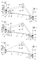
- a passenger compartment 1 of a motor vehicle represented partially is delimited by a floor 2, a dashboard 3 provided with a steering wheel 4, a front windshield 5 and a roof 6.
- a driver's front seat referenced 7 in his together is arranged facing the steering wheel 4.
- the seat 7 comprises a seat 8 and a backrest 9.
- a frame of the seat 7 is shown in bold lines, a quilting or seat trim 7 being delimited by dashed lines.
- the frame of the seat 7 comprises a seat portion 10 extending substantially horizontally with a slight inclination towards the rear and a portion of the backrest or support portion 11 extending substantially vertically and being substantially inclined rearwardly.
- the seat portion 10 of the frame is connected to the floor 2 via a seat connection in the form of a central stud or foot 12 and a lower connecting member 13, the foot 12 having an upper end attached to the seat portion 10 and a lower end attached to the lower connecting member 13.
- the bearing portion 11 and the seat portion 10 are connected by a curved connecting portion 14 forming a rigid lower back link between the seat portion 10 and the bearing portion 11.
- the bearing portion 11 is provided at its upper end with a fixing arm 15 extending upwards from the upper edge of the bearing portion 11, the end of the arm 15 opposite the bearing portion 11 being connected to an upper structural member of the motor vehicle by an upper connecting member 16.
- the upper connecting member 16 is disposed between the arm 15 and an upper spar 17 of the vehicle, that is to say a longitudinal structure of the vehicle element delimiting an upper edge of the roof 6.
- the passenger compartment 1 is limited laterally by an amount 18 located substantially next to the backrest 9 of the seat 7.
- Such an amount 18, called “foot-medium” is generally disposed between a rear door opening and a front door opening formed in the vehicle structure. Such an amount contributes to the rigidity of the structure of the motor vehicle, despite the necessary openings for access to the front and rear seats.
- the bearing portion 11 comprises two lateral uprights 19, 20, a lower cross member 21, an intermediate cross member 22, and an upper cross member 23.
- a portion of housing 24 is formed at the intersection of the upright 20 located on the side of the central foot 18 and the upper rail 23 of the armature of the bearing portion 11.
- the housing portion 24 is in the form of a substantially square profile frame for housing and fixing a not shown seat belt retractor, to form a top attachment point of a seat belt on the seat 7, which is also provided with means of lower attachment in the form of a first fastening lug 21a provided at the lateral end of the lower cross member 21, the side of the central foot 18, and a second fastening lug 21b provided at the opposite end of the lower cross member 21 of the bearing portion 11.
- the first lug 21a is provided for permanent attachment of one end of a safety belt, the other lug 21b being provided for the attachment of a removable attachment device of a intermediate portion seat belt area.
- a seat belt extending between the different attachment points is shown in phantom.
- the armature comprises a substantially vertical branch 26 connecting the arm 15 to the frame 24 and an oblique branch 26 connecting the arm 15 substantially in the middle of the upper rail 23 of the bearing portion 11.
- the upper and lower links of the seat 7 are adapted for adjustment of the longitudinal position of the seat 7 relative to the vehicle structure.
- the upper link member 16 is provided in the form of a first upper carriage 28 integral with the arm 15 and slidable on an upper longitudinal rail 29 secured to the upper structural element 17 shown schematically by a fixed point .
- the first carriage 28 can be moved longitudinally forwards or backwards relative to the upper structural element 17, as illustrated by the arrow F2.
- An upper locking member 30 integral with the first carriage 28 locked the position of the first carriage 28 on the upper rail 29.
- the upper locking member 30 can be unlocked.
- a seat connecting member 13 is provided in the form of a second lower carriage 31 secured to the foot 12 and slidable on a lower longitudinal rail 32 solitary floor 2, shown schematically by a fixed point.
- the lower carriage 31 can be moved longitudinally forwards or backwards relative to the lower rail 32, as illustrated by the arrow F3.
- a second lower locking member 33 secured to the second carriage 31, locks the position of the second carriage 31 on the lower rail 32.
- the lower locking member 33 can be unlocked.
- An actuator 34 associated with the second carriage 31 is able to cause displacement of the second carriage 31 along the lower rail 32 when the lower locking member 33 is unlocked.
- the actuator 34 may for example be of the electric motor type.
- the seat 7 comprises a control button 35 connected to a control unit 36, which is also connected to the upper locking member 30, to the lower locking member 33 and to the actuator 34.
- control 36 comprises memory means for storing a computer program comprising control modules for controlling actuators and locking members associated with seat link members 7 and a microprocessor for the implementation of such a program.
- the control unit 36 For adjustment of the longitudinal position of the seat 7 controlled from the control button 35, the control unit 36 causes the unlocking of the upper and lower locking members 33 and 33 then controls the actuator 34 for longitudinal displacement of the second trolley 31, which will cause the seat 7 as a whole. Once the desired position is reached, the locking members 30, 33 are locked to maintain the seat 7 in position.
- the grooves 30, 33 in the locked position are sized to retain the seat 7 in case of shock suffered by the motor vehicle. It will preferably be provided that the locking members 30, 33 are in the locked position by default, for example being biased by resilient elements of the spring type.
- the locking members 30, 33 will in this case be equipped with an actuator controlled from the control unit 36, and capable of exerting unlocking forces against the elastic elements.
- An actuator associated with the lower link member 13 has been described.
- An associated actuator could be provided with the upper link member 16, or two actuators, ie one for the lower link member 13. and another for the upper link member 16.
- the seat 7 is devoid of actuator, and that the locking members 30, 33 is provided with manual unlocking means.
- the armature of the seat 7, connecting the floor 2 of the passenger compartment to the spar 17 of the roof 6 contributes to the overall rigidity of the structure of the motor vehicle, which in particular improves the protection of the occupants in case of accident, in particular in case of overturning of the vehicle or in the event of a side impact suffered by the vehicle, by reinforcing the cell of the passenger compartment of the vehicle.
- the seat When the locking members are locked, the seat is held by a lower part and an upper part of the backrest so that one can provide a light and space-saving frame while ensuring the rigidity of the seat.
- the backrest As the upper part of the backrest is retained by an upper link, the backrest has improved resistance in the event of a front impact of the vehicle. Therefore, one can provide a safety belt device embedded on the seat.
- a seat belt device on a seat allows better positioning of the seat belt on the passenger's torso despite seat position and backrest angle adjustments, and improved seatbelt action to prevent or mitigate trauma to the passenger in the event of shock of the vehicle with an obstacle.
- an upper link and a lower link of the seat provides for less resistant and less bulky links, while improving the strength of the seat. So, as we can see on the figure 2 it can be provided a lower attachment with a central foot to clear an available space under the seat cushion.
- the seat 7 differs from the previous embodiment in that the backrest 9 is connected to the seat 8 via a lower backrest joint 42 able to allow a relative angular displacement between the backrest 9 and the seat 8 along a transverse axis, and furthermore in that the arm 15 is connected to the upper connecting member 16 by an intermediate link 38.
- the upper connecting member 16 is associated with an upper actuator 39 connected to the control unit 36.
- the intermediate link 38 is provided to allow at least one relative angular displacement between the backrest 9 and the upper connecting member 16, along a transverse axis, and a translation in a longitudinal plane of the backrest 9 relative to the upper connecting member. 16, along an axis differ from a longitudinal axis.
- the intermediate link 38 is pre-drilled in the illustrated embodiment in the form of an intermediate element 40 connected at one end to the first upper carriage 28 by a pivot link 41a having a degree of freedom in rotation along a transverse axis, and connected to the opposite side to the arm 15 via a sliding pivot connection 41b, the sliding pivot connection 41b allowing a degree of freedom in rotation along an axis situated in a longitudinal plane, that is to say in the plane of the figure, and a rotation along the same axis.
- the translation axis of the pivot-sliding link 41b is here substantially vertical.
- This embodiment makes it possible to increase the possibilities of adjusting the position of the seat 7.
- the adjustments of the seat 7 can be made by acting only on the longitudinal positions of the upper carriages 28 and lower 31.
- An adjustment of the inclination of the backrest 9 can be achieved by moving the first carriage 28 relative to the second carriage 31.
- the position of the axis of the pivot-sliding connection 41b varies during the inclination of the backrest 9. It will be provided that in a range of adjustment of the inclination of the backrest 9, the axis of the pivot-sliding connection 41b is never aligned with the longitudinal axis of movement of the first carriage 28, to ensure that a simultaneous locking of the first and second carriage 28, 31 causes a locking of the backrest and the seat as a whole.
- the control button 35 may be provided to allow both a control of the longitudinal position of the seat 7 and a control of inclination of the backrest 9.
- the control unit 36 may unlock the locking members 30, 33 of the lower connecting member 13 and the upper connecting member 16 according to whether they must be moved or not, and synchronously control the lower connecting member 13 and the upper connecting member 16 to obtain the desired longitudinal position and the inclination of the desired backrest 9.
- the upper link, formed by the carriage 28, the pivot connection 41a, and the pivot-sliding connection 41b, and the lower link formed by the second carriage 31 are adapted to allow a simple adjustment of the seat requiring a number of limited actuators.
- the seat 7 differs from the preceding embodiment in that the lower hinge of the back is replaced by an intermediate hinge 43 of transverse axis provided between the foot 12 and the lower carriage 31. Therefore, in case relative displacement in a longitudinal direction of the first carriage 28 and the second carriage 31, we will obtain a tilting of the seat 7 as a whole about an axis defined by the intermediate joint 43.
- the intermediate articulation 43 is provided with locking means to allow a maintenance of the position of the seat 8, and possibly a position control actuator.
- a dashboard 3 can be moved longitudinally to adjust the position of the steering wheel and a pedal (not shown) of the control buttons relative to the seat 8 of the seat assembly 7, as represented by an arrow F1 on the figure 1 .
- connection between the arm 15 and the first carriage 28 there is described a particular embodiment for the intermediate connection between the arm 15 and the first carriage 28.
- the invention is not limited to this embodiment. It is possible to provide any connection or combination of connections allowing both a displacement in a longitudinal plane of the backrest relative to the structural element and an angular displacement along a transverse axis, while being able to prohibit displacement of an upper part of the backrest when locking devices are locked.
- the arm 15 is connected to the intermediate element 40 by a transverse axis pivot connection, and that the intermediate element 40 is connected to the first carriage 28 by a slide connection or a pivot-sliding connection.
- the arm 15 is connected by a transverse axis pivot connection to a slider able to slide on a rail integral with the first carriage, the rail extending downwards in a direction situated in a longitudinal plane and different the longitudinal direction of movement of the carriage.
- a seat is obtained for lightening the frame of a seat while increasing the rigidity of the seat, especially in case of shock.
- the seat can be adapted to allow ergonomic adjustments of the seat position.
- the adjustments of the seat position can be obtained simply from a limited number of actuators.
- the lightweight seat frame allows to preserve the living space of a passenger compartment of the motor vehicle, in particular for rear passengers.
- the seat can be used to stiffen the structure of the motor vehicle as a whole.
Landscapes
- Engineering & Computer Science (AREA)
- Aviation & Aerospace Engineering (AREA)
- Transportation (AREA)
- Mechanical Engineering (AREA)
- Seats For Vehicles (AREA)
- Chair Legs, Seat Parts, And Backrests (AREA)
Claims (10)
- Verstellbarer Kraftfahrzeugsitz, der eine Sitzfläche (8), eine untere Verbindungsvorrichtung (13) zur Verbindung der Sitzfläche mit einem unteren Fahrzeugstrukturelement (2) und eine Rückenlehne (9) umfasst, wobei der Sitz so ausgebildet ist, dass er in seiner Gebrauchsposition das Verstellen der Position des Sitzes gestattet, dadurch gekennzeichnet, dass er eine obere Verbindungsvorrichtung (16) zur Verbindung eines oberen Teils (15) der Rückenlehne mit einem oberen Strukturelement (17) des Fahrzeugs umfasst, wobei die obere Verbindungsvorrichtung (16) geeignet ist, eine obere Verbindung zu bilden, die das Verstellen der Position des Sitzes in seiner Gebrauchsposition gestattet.
- Sitz nach Anspruch 1, dadurch gekennzeichnet, dass die obere Verbindungsvorrichtung (16) mit dem oberen Rückenlehnenteil (15) über eine obere Zwischenverbindung (38) verbunden ist, die geeignet ist, eine Verschiebung des oberen Rückenlehnenteils (15) bezüglich der oberen Verbindungsvorrichtung (16) mit einer Drehung gemäß einer ersten Querachse und einer Translation gemäß einer zweiten Achse, die in einer Längsebene liegt und von einer Längsachse verschieden ist, zu gestatten.
- Sitz nach Anspruch 1 oder 2, dadurch gekennzeichnet, dass die Sitzfläche (8) über ein Zwischengelenk mit Querachse mit der unteren Verbindungsvorrichtung (13) verbunden ist.
- Sitz nach einem der vorhergehenden Ansprüche, dadurch gekennzeichnet, dass die Rückenlehne (9) über ein unteres Rückenlehnengelenk (42) mit Querachse mit der Sitzfläche verbunden ist.
- Sitz nach einem der Ansprüche 2 bis 4, dadurch gekennzeichnet, dass die obere Verbindungsvorrichtung (16) dazu vorgesehen ist, bezüglich eines oberen Strukturelements fest zu sein, und die untere Verbindungsvorrichtung (13) geeignet ist, so montiert zu sein, dass die Möglichkeit einer Verschiebung bezüglich eines unteren Strukturelements des Fahrzeugs gemäß einer Längsachse besteht.
- Sitz nach einem der Ansprüche 2 bis 4, dadurch gekennzeichnet, dass die obere Verbindungsvorrichtung (16) geeignet ist, so montiert zu sein, dass die Möglichkeit einer Verschiebung bezüglich eines oberen Strukturelements des Fahrzeugs gemäß einer Längsachse besteht, und die untere Verbindungsvorrichtung (13) dazu vorgesehen ist, bezüglich eines unteren Strukturelements fest zu sein.
- Sitz nach einem der Ansprüche 1 bis 4, dadurch gekennzeichnet, dass die obere Verbindungsvorrichtung (16) geeignet ist, so montiert zu sein, dass die Möglichkeit einer Verschiebung bezüglich eines oberen Strukturelements (17) des Fahrzeugs gemäß einer Längsachse besteht, und die untere Verbindungsvorrichtung (13) geeignet ist, so montiert zu sein, dass die Möglichkeit einer Verschiebung bezüglich eines unteren Strukturelements des Fahrzeugs gemäß einer Längsachse besteht.
- Sitz nach einem der vorhergehenden Ansprüche, dadurch gekennzeichnet, dass eine Verbindung mit Blockiermitteln (30, 33) versehen ist, die entriegelt werden können.
- Kraftfahrzeug, das mit mindestens einem Sitz nach einem der vorhergehenden Ansprüche ausgerüstet ist, wobei der Sitz (7) über die Sitzflächenverbindung (13) mit einem Boden (2) des Fahrzeugs und über die obere Rückenlehnenverbindung (16) mit einem oberen Strukturelement (17) des Kraftfahrzeugs verbunden ist.
- Fahrzeug nach Anspruch 9, dadurch gekennzeichnet, dass es eine Steuereinheit (3) umfasst, die gemäß einer Längsachse bezüglich des Sitzes (7) beweglich ist.
Applications Claiming Priority (2)
| Application Number | Priority Date | Filing Date | Title |
|---|---|---|---|
| FR0313550A FR2862259B1 (fr) | 2003-11-19 | 2003-11-19 | Siege pour vehicule automobile, et vehicule automobile equipe d'un tel siege. |
| PCT/FR2004/050576 WO2005051704A1 (fr) | 2003-11-19 | 2004-11-09 | Siege reglable pour vehicule automobile, et vehicule automobile equipe d'un tel siege. |
Publications (2)
| Publication Number | Publication Date |
|---|---|
| EP1687178A1 EP1687178A1 (de) | 2006-08-09 |
| EP1687178B1 true EP1687178B1 (de) | 2010-02-24 |
Family
ID=34508585
Family Applications (1)
| Application Number | Title | Priority Date | Filing Date |
|---|---|---|---|
| EP04805819A Expired - Lifetime EP1687178B1 (de) | 2003-11-19 | 2004-11-09 | Verstellbarer sitz für ein kraftfahrzeug und mit dem sitz versehenes kraftfahrzeug |
Country Status (7)
| Country | Link |
|---|---|
| US (1) | US7618076B2 (de) |
| EP (1) | EP1687178B1 (de) |
| JP (1) | JP4794456B2 (de) |
| AT (1) | ATE458644T1 (de) |
| DE (1) | DE602004025727D1 (de) |
| FR (1) | FR2862259B1 (de) |
| WO (1) | WO2005051704A1 (de) |
Families Citing this family (13)
| Publication number | Priority date | Publication date | Assignee | Title |
|---|---|---|---|---|
| FR2885088B1 (fr) * | 2005-05-02 | 2009-02-13 | Renault Sas | Ensemble de sieges pour vehicule automobile |
| FR2896456B1 (fr) | 2006-01-23 | 2008-03-07 | Renault Sas | Siege reglable pour vehicule automobile. |
| FR2896457B1 (fr) | 2006-01-23 | 2009-10-02 | Renault Sas | Vehicule automobile pourvu de sieges comprenant une structure d'assise commune. |
| FR2932428B1 (fr) * | 2008-06-13 | 2010-08-20 | Nexter Systems | Siege pour vehicule blinde. |
| FR2936452A1 (fr) * | 2008-09-29 | 2010-04-02 | Cera | Architecture de montage d'un dossier de siege de vehicule automobile |
| FR2936748B1 (fr) * | 2008-10-07 | 2010-09-24 | Peugeot Citroen Automobiles Sa | "habitacle de vehicule automobile avec un dispositif de maintien d'un siege par rapport a un cote lateral dudit habitacle" |
| FR2952591B1 (fr) * | 2009-11-16 | 2012-02-24 | Antolin Grupo Ing Sa | Amenagement d'interieur de vehicule |
| DE102010013985B4 (de) * | 2010-04-06 | 2019-02-14 | Colibri Innovative Mobility Automobile Gmbh | Fahrzeugrahmen |
| WO2012134448A1 (en) * | 2011-03-29 | 2012-10-04 | Lear Corporation | Pedestal-type support for a vehicle seat assembly |
| US8573675B2 (en) * | 2011-11-07 | 2013-11-05 | Ford Global Technologies, Llc | Reverse pedestal seat |
| US9327623B2 (en) | 2011-12-16 | 2016-05-03 | Wichita State University | Energy absorbing seat mechanism |
| US10343730B2 (en) * | 2014-12-17 | 2019-07-09 | Volvo Truck Corporation | Adjustable bunk and vehicle equipped with the same |
| CN107972543B (zh) * | 2017-12-02 | 2024-03-26 | 芜湖瑞泰汽车零部件有限公司 | 一种靠背能够调节的汽车座椅结构 |
Family Cites Families (14)
| Publication number | Priority date | Publication date | Assignee | Title |
|---|---|---|---|---|
| DE2253307C3 (de) * | 1972-10-31 | 1979-04-12 | Adam Opel Ag, 6090 Ruesselsheim | Mit Sicherheitsgurten ausgerüsteter Fahrzeugsitz mit verstellbarer Rückenlehne |
| US3922029A (en) * | 1973-04-20 | 1975-11-25 | Saito Takeji | Seat mounting device for vehicle |
| JPS5239525B2 (de) * | 1973-04-20 | 1977-10-05 | ||
| JPS6194829A (ja) * | 1984-10-15 | 1986-05-13 | Toyoda Autom Loom Works Ltd | 自動車 |
| JPS61111355A (ja) * | 1984-11-06 | 1986-05-29 | Toray Ind Inc | ポリエステル樹脂組成物 |
| JPS61147629A (ja) * | 1984-12-21 | 1986-07-05 | Toshiba Corp | パタ−ン検出回路 |
| JPH0231001Y2 (de) * | 1984-12-26 | 1990-08-21 | ||
| JPH0428268Y2 (de) * | 1985-03-06 | 1992-07-08 | ||
| FR2663270B1 (fr) * | 1990-06-13 | 1992-09-18 | Durisotti Sa | Siege et notamment banquette repliable pour vehicules automobiles. |
| FR2716649B1 (fr) * | 1994-02-25 | 1996-05-31 | Faure France Bertrand | Dispositif de positionnement longitudinal d'un siège de véhicule. |
| FR2725669A1 (fr) * | 1994-10-13 | 1996-04-19 | Renault | Siege escamotable a dossier mobile |
| US6073986A (en) * | 1997-03-14 | 2000-06-13 | Magna Interior Systems, Inc. | Easily handled movable vehicle seat assembly |
| FR2801851B1 (fr) * | 1999-12-03 | 2002-02-15 | Renault | Siege reglable pour vehicule automobile |
| US7597395B2 (en) * | 2002-01-04 | 2009-10-06 | Honda Giken Kogyo Kabushiki Kaisha | Vehicle seat |
-
2003
- 2003-11-19 FR FR0313550A patent/FR2862259B1/fr not_active Expired - Fee Related
-
2004
- 2004-11-09 WO PCT/FR2004/050576 patent/WO2005051704A1/fr not_active Ceased
- 2004-11-09 AT AT04805819T patent/ATE458644T1/de not_active IP Right Cessation
- 2004-11-09 DE DE602004025727T patent/DE602004025727D1/de not_active Expired - Lifetime
- 2004-11-09 US US10/580,002 patent/US7618076B2/en not_active Expired - Fee Related
- 2004-11-09 JP JP2006540552A patent/JP4794456B2/ja not_active Expired - Fee Related
- 2004-11-09 EP EP04805819A patent/EP1687178B1/de not_active Expired - Lifetime
Also Published As
| Publication number | Publication date |
|---|---|
| FR2862259B1 (fr) | 2006-01-13 |
| US20070075561A1 (en) | 2007-04-05 |
| FR2862259A1 (fr) | 2005-05-20 |
| EP1687178A1 (de) | 2006-08-09 |
| WO2005051704A1 (fr) | 2005-06-09 |
| US7618076B2 (en) | 2009-11-17 |
| JP2007511417A (ja) | 2007-05-10 |
| ATE458644T1 (de) | 2010-03-15 |
| JP4794456B2 (ja) | 2011-10-19 |
| DE602004025727D1 (de) | 2010-04-08 |
Similar Documents
| Publication | Publication Date | Title |
|---|---|---|
| EP1687178B1 (de) | Verstellbarer sitz für ein kraftfahrzeug und mit dem sitz versehenes kraftfahrzeug | |
| JP5214610B2 (ja) | 車両座席 | |
| US7758126B2 (en) | Folding headrest | |
| FR3042450A1 (fr) | Accoudoir escamotable pour siege avant de vehicule automobile | |
| FR2895336A1 (fr) | Appui-tete escamotable pour vehicule automobile | |
| FR2899160A1 (fr) | Siege arriere reglable de vehicule automobile | |
| CN113696799A (zh) | 横向平移座椅台座 | |
| EP1808330B1 (de) | Sitz für Kraftfahrzeug, der entlang einer ersten Achse x und einer zweiten Achse y beweglich ist, und Kraftfahrzeug, das einen solchen Sitz umfasst | |
| EP1719659B1 (de) | Kraftfahrzeugsitz, klappbar in zumindest eine Position | |
| FR3074111A1 (fr) | Siege de vehicule comprenant un verin pneumatique | |
| FR2862260A1 (fr) | Siege pour vehicule automobile, et vehicule automobile equipe d'un tel siege | |
| EP1640206B1 (de) | Verstellvorrichtung eines Kraftfahrzeugsitzes | |
| FR3073465B1 (fr) | Siege de vehicule comprenant une assise et un accoudoir | |
| FR2870800A1 (fr) | Equipement de dossier de siege de vehicule automobile et dossier muni d'un tel equipement | |
| FR2896457A1 (fr) | Vehicule automobile pourvu de sieges comprenant une structure d'assise commune. | |
| EP3877211B1 (de) | Versenkbarer sitz für ein kraftfahrzeug und fahrzeug mit solch einem sitz | |
| FR2889825A3 (fr) | Agencement d'habitacle de vehicule comportant des sieges mobiles | |
| FR3138382A1 (fr) | Dossier de siège de véhicule muni d’un dispositif de réglage haut de dossier et d’un dispositif de coussin gonflable de sécurité, et siège de véhicule comprenant un tel dossier | |
| FR3152446A1 (fr) | Ensemble de sièges de véhicule à assise inclinable pour faciliter l’accès aux places arrière | |
| FR2875191A1 (fr) | Siege de vehicule ayant un appui-tete pouvant se deplacer entre une position arriere et une position avant de retenue en cas de choc arriere | |
| FR3143465A1 (fr) | Système de commande pour dispositif/s de verrouillage pour siège de véhicule, notamment pour dispositif/s de verrouillage d’une glissière de siège de véhicule | |
| FR2873067A1 (fr) | Siege, notamment pour vehicule automobile | |
| FR3092285A1 (fr) | Siège de véhicule automobile à dossier réversible motorisé | |
| CN114728605A (zh) | 座椅 | |
| FR2879975A1 (fr) | Siege de voiture automobile comprenant un dossier pourvu d'une coque |
Legal Events
| Date | Code | Title | Description |
|---|---|---|---|
| PUAI | Public reference made under article 153(3) epc to a published international application that has entered the european phase |
Free format text: ORIGINAL CODE: 0009012 |
|
| 17P | Request for examination filed |
Effective date: 20060619 |
|
| AK | Designated contracting states |
Kind code of ref document: A1 Designated state(s): AT BE BG CH CY CZ DE DK EE ES FI FR GB GR HU IE IS IT LI LU MC NL PL PT RO SE SI SK TR |
|
| DAX | Request for extension of the european patent (deleted) | ||
| 17Q | First examination report despatched |
Effective date: 20080215 |
|
| GRAP | Despatch of communication of intention to grant a patent |
Free format text: ORIGINAL CODE: EPIDOSNIGR1 |
|
| GRAS | Grant fee paid |
Free format text: ORIGINAL CODE: EPIDOSNIGR3 |
|
| GRAA | (expected) grant |
Free format text: ORIGINAL CODE: 0009210 |
|
| AK | Designated contracting states |
Kind code of ref document: B1 Designated state(s): AT BE BG CH CY CZ DE DK EE ES FI FR GB GR HU IE IS IT LI LU MC NL PL PT RO SE SI SK TR |
|
| REG | Reference to a national code |
Ref country code: GB Ref legal event code: FG4D Free format text: NOT ENGLISH |
|
| REG | Reference to a national code |
Ref country code: CH Ref legal event code: EP |
|
| REG | Reference to a national code |
Ref country code: IE Ref legal event code: FG4D Free format text: LANGUAGE OF EP DOCUMENT: FRENCH |
|
| REF | Corresponds to: |
Ref document number: 602004025727 Country of ref document: DE Date of ref document: 20100408 Kind code of ref document: P |
|
| REG | Reference to a national code |
Ref country code: NL Ref legal event code: VDEP Effective date: 20100224 |
|
| PG25 | Lapsed in a contracting state [announced via postgrant information from national office to epo] |
Ref country code: PT Free format text: LAPSE BECAUSE OF FAILURE TO SUBMIT A TRANSLATION OF THE DESCRIPTION OR TO PAY THE FEE WITHIN THE PRESCRIBED TIME-LIMIT Effective date: 20100625 Ref country code: IS Free format text: LAPSE BECAUSE OF FAILURE TO SUBMIT A TRANSLATION OF THE DESCRIPTION OR TO PAY THE FEE WITHIN THE PRESCRIBED TIME-LIMIT Effective date: 20100624 |
|
| PG25 | Lapsed in a contracting state [announced via postgrant information from national office to epo] |
Ref country code: SI Free format text: LAPSE BECAUSE OF FAILURE TO SUBMIT A TRANSLATION OF THE DESCRIPTION OR TO PAY THE FEE WITHIN THE PRESCRIBED TIME-LIMIT Effective date: 20100224 Ref country code: AT Free format text: LAPSE BECAUSE OF FAILURE TO SUBMIT A TRANSLATION OF THE DESCRIPTION OR TO PAY THE FEE WITHIN THE PRESCRIBED TIME-LIMIT Effective date: 20100224 Ref country code: FI Free format text: LAPSE BECAUSE OF FAILURE TO SUBMIT A TRANSLATION OF THE DESCRIPTION OR TO PAY THE FEE WITHIN THE PRESCRIBED TIME-LIMIT Effective date: 20100224 Ref country code: PL Free format text: LAPSE BECAUSE OF FAILURE TO SUBMIT A TRANSLATION OF THE DESCRIPTION OR TO PAY THE FEE WITHIN THE PRESCRIBED TIME-LIMIT Effective date: 20100224 |
|
| REG | Reference to a national code |
Ref country code: IE Ref legal event code: FD4D |
|
| PG25 | Lapsed in a contracting state [announced via postgrant information from national office to epo] |
Ref country code: CY Free format text: LAPSE BECAUSE OF FAILURE TO SUBMIT A TRANSLATION OF THE DESCRIPTION OR TO PAY THE FEE WITHIN THE PRESCRIBED TIME-LIMIT Effective date: 20100224 Ref country code: IE Free format text: LAPSE BECAUSE OF FAILURE TO SUBMIT A TRANSLATION OF THE DESCRIPTION OR TO PAY THE FEE WITHIN THE PRESCRIBED TIME-LIMIT Effective date: 20100224 Ref country code: GR Free format text: LAPSE BECAUSE OF FAILURE TO SUBMIT A TRANSLATION OF THE DESCRIPTION OR TO PAY THE FEE WITHIN THE PRESCRIBED TIME-LIMIT Effective date: 20100525 Ref country code: NL Free format text: LAPSE BECAUSE OF FAILURE TO SUBMIT A TRANSLATION OF THE DESCRIPTION OR TO PAY THE FEE WITHIN THE PRESCRIBED TIME-LIMIT Effective date: 20100224 Ref country code: RO Free format text: LAPSE BECAUSE OF FAILURE TO SUBMIT A TRANSLATION OF THE DESCRIPTION OR TO PAY THE FEE WITHIN THE PRESCRIBED TIME-LIMIT Effective date: 20100224 Ref country code: SE Free format text: LAPSE BECAUSE OF FAILURE TO SUBMIT A TRANSLATION OF THE DESCRIPTION OR TO PAY THE FEE WITHIN THE PRESCRIBED TIME-LIMIT Effective date: 20100224 Ref country code: ES Free format text: LAPSE BECAUSE OF FAILURE TO SUBMIT A TRANSLATION OF THE DESCRIPTION OR TO PAY THE FEE WITHIN THE PRESCRIBED TIME-LIMIT Effective date: 20100604 Ref country code: EE Free format text: LAPSE BECAUSE OF FAILURE TO SUBMIT A TRANSLATION OF THE DESCRIPTION OR TO PAY THE FEE WITHIN THE PRESCRIBED TIME-LIMIT Effective date: 20100224 |
|
| PG25 | Lapsed in a contracting state [announced via postgrant information from national office to epo] |
Ref country code: BG Free format text: LAPSE BECAUSE OF FAILURE TO SUBMIT A TRANSLATION OF THE DESCRIPTION OR TO PAY THE FEE WITHIN THE PRESCRIBED TIME-LIMIT Effective date: 20100524 Ref country code: SK Free format text: LAPSE BECAUSE OF FAILURE TO SUBMIT A TRANSLATION OF THE DESCRIPTION OR TO PAY THE FEE WITHIN THE PRESCRIBED TIME-LIMIT Effective date: 20100224 Ref country code: CZ Free format text: LAPSE BECAUSE OF FAILURE TO SUBMIT A TRANSLATION OF THE DESCRIPTION OR TO PAY THE FEE WITHIN THE PRESCRIBED TIME-LIMIT Effective date: 20100224 |
|
| PLBE | No opposition filed within time limit |
Free format text: ORIGINAL CODE: 0009261 |
|
| STAA | Information on the status of an ep patent application or granted ep patent |
Free format text: STATUS: NO OPPOSITION FILED WITHIN TIME LIMIT |
|
| PG25 | Lapsed in a contracting state [announced via postgrant information from national office to epo] |
Ref country code: DK Free format text: LAPSE BECAUSE OF FAILURE TO SUBMIT A TRANSLATION OF THE DESCRIPTION OR TO PAY THE FEE WITHIN THE PRESCRIBED TIME-LIMIT Effective date: 20100224 |
|
| 26N | No opposition filed |
Effective date: 20101125 |
|
| PG25 | Lapsed in a contracting state [announced via postgrant information from national office to epo] |
Ref country code: IT Free format text: LAPSE BECAUSE OF FAILURE TO SUBMIT A TRANSLATION OF THE DESCRIPTION OR TO PAY THE FEE WITHIN THE PRESCRIBED TIME-LIMIT Effective date: 20100224 |
|
| BERE | Be: lapsed |
Owner name: RENAULT S.A.S. Effective date: 20101130 |
|
| PG25 | Lapsed in a contracting state [announced via postgrant information from national office to epo] |
Ref country code: MC Free format text: LAPSE BECAUSE OF NON-PAYMENT OF DUE FEES Effective date: 20101130 |
|
| REG | Reference to a national code |
Ref country code: CH Ref legal event code: PL |
|
| PG25 | Lapsed in a contracting state [announced via postgrant information from national office to epo] |
Ref country code: LI Free format text: LAPSE BECAUSE OF NON-PAYMENT OF DUE FEES Effective date: 20101130 Ref country code: CH Free format text: LAPSE BECAUSE OF NON-PAYMENT OF DUE FEES Effective date: 20101130 |
|
| PG25 | Lapsed in a contracting state [announced via postgrant information from national office to epo] |
Ref country code: BE Free format text: LAPSE BECAUSE OF NON-PAYMENT OF DUE FEES Effective date: 20101130 |
|
| PG25 | Lapsed in a contracting state [announced via postgrant information from national office to epo] |
Ref country code: LU Free format text: LAPSE BECAUSE OF NON-PAYMENT OF DUE FEES Effective date: 20101109 Ref country code: HU Free format text: LAPSE BECAUSE OF FAILURE TO SUBMIT A TRANSLATION OF THE DESCRIPTION OR TO PAY THE FEE WITHIN THE PRESCRIBED TIME-LIMIT Effective date: 20100825 |
|
| PG25 | Lapsed in a contracting state [announced via postgrant information from national office to epo] |
Ref country code: TR Free format text: LAPSE BECAUSE OF FAILURE TO SUBMIT A TRANSLATION OF THE DESCRIPTION OR TO PAY THE FEE WITHIN THE PRESCRIBED TIME-LIMIT Effective date: 20100224 |
|
| REG | Reference to a national code |
Ref country code: FR Ref legal event code: PLFP Year of fee payment: 12 |
|
| PGFP | Annual fee paid to national office [announced via postgrant information from national office to epo] |
Ref country code: DE Payment date: 20151119 Year of fee payment: 12 Ref country code: GB Payment date: 20151118 Year of fee payment: 12 |
|
| PGFP | Annual fee paid to national office [announced via postgrant information from national office to epo] |
Ref country code: FR Payment date: 20151119 Year of fee payment: 12 |
|
| REG | Reference to a national code |
Ref country code: DE Ref legal event code: R119 Ref document number: 602004025727 Country of ref document: DE |
|
| GBPC | Gb: european patent ceased through non-payment of renewal fee |
Effective date: 20161109 |
|
| REG | Reference to a national code |
Ref country code: FR Ref legal event code: ST Effective date: 20170731 |
|
| PG25 | Lapsed in a contracting state [announced via postgrant information from national office to epo] |
Ref country code: FR Free format text: LAPSE BECAUSE OF NON-PAYMENT OF DUE FEES Effective date: 20161130 |
|
| PG25 | Lapsed in a contracting state [announced via postgrant information from national office to epo] |
Ref country code: GB Free format text: LAPSE BECAUSE OF NON-PAYMENT OF DUE FEES Effective date: 20161109 Ref country code: DE Free format text: LAPSE BECAUSE OF NON-PAYMENT OF DUE FEES Effective date: 20170601 |