EP1686643B1 - Verfahren und Vorrichtung zur thermischen, mechanischen und elektrischen Optimierung eines Festoxydbrennstoffzellenstapels - Google Patents
Verfahren und Vorrichtung zur thermischen, mechanischen und elektrischen Optimierung eines Festoxydbrennstoffzellenstapels Download PDFInfo
- Publication number
- EP1686643B1 EP1686643B1 EP06075099A EP06075099A EP1686643B1 EP 1686643 B1 EP1686643 B1 EP 1686643B1 EP 06075099 A EP06075099 A EP 06075099A EP 06075099 A EP06075099 A EP 06075099A EP 1686643 B1 EP1686643 B1 EP 1686643B1
- Authority
- EP
- European Patent Office
- Prior art keywords
- stack
- sub
- temperature
- fuel gas
- heat exchanger
- Prior art date
- Legal status (The legal status is an assumption and is not a legal conclusion. Google has not performed a legal analysis and makes no representation as to the accuracy of the status listed.)
- Expired - Lifetime
Links
Images


Classifications
-
- H—ELECTRICITY
- H01—ELECTRIC ELEMENTS
- H01M—PROCESSES OR MEANS, e.g. BATTERIES, FOR THE DIRECT CONVERSION OF CHEMICAL ENERGY INTO ELECTRICAL ENERGY
- H01M8/00—Fuel cells; Manufacture thereof
- H01M8/04—Auxiliary arrangements, e.g. for control of pressure or for circulation of fluids
- H01M8/04007—Auxiliary arrangements, e.g. for control of pressure or for circulation of fluids related to heat exchange
-
- H—ELECTRICITY
- H01—ELECTRIC ELEMENTS
- H01M—PROCESSES OR MEANS, e.g. BATTERIES, FOR THE DIRECT CONVERSION OF CHEMICAL ENERGY INTO ELECTRICAL ENERGY
- H01M8/00—Fuel cells; Manufacture thereof
- H01M8/04—Auxiliary arrangements, e.g. for control of pressure or for circulation of fluids
- H01M8/04082—Arrangements for control of reactant parameters, e.g. pressure or concentration
- H01M8/04089—Arrangements for control of reactant parameters, e.g. pressure or concentration of gaseous reactants
-
- H—ELECTRICITY
- H01—ELECTRIC ELEMENTS
- H01M—PROCESSES OR MEANS, e.g. BATTERIES, FOR THE DIRECT CONVERSION OF CHEMICAL ENERGY INTO ELECTRICAL ENERGY
- H01M8/00—Fuel cells; Manufacture thereof
- H01M8/04—Auxiliary arrangements, e.g. for control of pressure or for circulation of fluids
- H01M8/04082—Arrangements for control of reactant parameters, e.g. pressure or concentration
- H01M8/04089—Arrangements for control of reactant parameters, e.g. pressure or concentration of gaseous reactants
- H01M8/04097—Arrangements for control of reactant parameters, e.g. pressure or concentration of gaseous reactants with recycling of the reactants
-
- H—ELECTRICITY
- H01—ELECTRIC ELEMENTS
- H01M—PROCESSES OR MEANS, e.g. BATTERIES, FOR THE DIRECT CONVERSION OF CHEMICAL ENERGY INTO ELECTRICAL ENERGY
- H01M8/00—Fuel cells; Manufacture thereof
- H01M8/24—Grouping of fuel cells, e.g. stacking of fuel cells
- H01M8/249—Grouping of fuel cells, e.g. stacking of fuel cells comprising two or more groupings of fuel cells, e.g. modular assemblies
-
- H—ELECTRICITY
- H01—ELECTRIC ELEMENTS
- H01M—PROCESSES OR MEANS, e.g. BATTERIES, FOR THE DIRECT CONVERSION OF CHEMICAL ENERGY INTO ELECTRICAL ENERGY
- H01M8/00—Fuel cells; Manufacture thereof
- H01M8/10—Fuel cells with solid electrolytes
- H01M8/12—Fuel cells with solid electrolytes operating at high temperature, e.g. with stabilised ZrO2 electrolyte
- H01M2008/1293—Fuel cells with solid oxide electrolytes
-
- Y—GENERAL TAGGING OF NEW TECHNOLOGICAL DEVELOPMENTS; GENERAL TAGGING OF CROSS-SECTIONAL TECHNOLOGIES SPANNING OVER SEVERAL SECTIONS OF THE IPC; TECHNICAL SUBJECTS COVERED BY FORMER USPC CROSS-REFERENCE ART COLLECTIONS [XRACs] AND DIGESTS
- Y02—TECHNOLOGIES OR APPLICATIONS FOR MITIGATION OR ADAPTATION AGAINST CLIMATE CHANGE
- Y02E—REDUCTION OF GREENHOUSE GAS [GHG] EMISSIONS, RELATED TO ENERGY GENERATION, TRANSMISSION OR DISTRIBUTION
- Y02E60/00—Enabling technologies; Technologies with a potential or indirect contribution to GHG emissions mitigation
- Y02E60/30—Hydrogen technology
- Y02E60/50—Fuel cells
Definitions
- the present invention relates to fuel cells; more particularly to solid-oxide fuel cells; and most particularly to arrangements for optimizing the operating conditions, longevity, efficiency, fuel utilization, and electrical output of a solid-oxide fuel cell stack.
- Fuel cells for combining hydrogen and oxygen to produce electricity are well known.
- a known class of fuel cells includes a solid-oxide electrolyte layer through which oxygen anions migrate; such fuel cells are referred to in the art as "solid-oxide” fuel cells (SOFCs).
- SOFCs solid-oxide fuel cells
- an SOFC is preferably fueled by "reformate” gas, which is the effluent from a catalytic liquid or gaseous hydrocarbon oxidizing reformer, also referred to herein as "fuel gas".
- Reformate typically includes amounts of carbon monoxide (CO) as fuel in addition to molecular hydrogen.
- CO carbon monoxide
- the reforming operation and the fuel cell operation may be considered as first and second oxidative steps of the hydrocarbon fuel, resulting ultimately in water and carbon dioxide. Both reactions are preferably carried out at relatively high temperatures, for example, in the range of 700°C to 1000°C.
- a complete fuel cell stack assembly includes a plurality of fuel cells, for example, 60 cells in the form of sub-assemblies, and a plurality of components known in the art as interconnects which electrically connect the individual fuel cell subassemblies in series electrically.
- the interconnects include a conductive foam or weave disposed in the fuel gas and air flow spaces adjacent the anodes and cathodes of the fuel cells.
- each subassembly contains porting which, when joined to the porting of adjacent subassemblies, creates a supply manifold and an exhaust manifold for both the cathode air to the plurality of cathodes and the fuel gas to the plurality of anodes.
- all of the cathodes are in parallel pneumatic flow and all of the anodes are in parallel pneumatic flow.
- the total air is divided among the plurality of cathodes such that each increment of air passes over only a single cathode and then is collected in the air exhaust manifold.
- the total fuel gas entering the stack assembly is divided among the plurality of anodes such that each increment of fuel gas passes over only a single anode and is then collected in the fuel gas exhaust manifold.
- This flow scheme is sensitive to uneven flow distribution at low anode flow rates. Generally, only a portion of the fuel cell gas is consumed, or utilized, in the single pass through the stack. High fuel utilization is desirable for high system efficiency; however, stack power density decreases with increasing fuel utilization due to fuel gas concentration gradients in the SOFC stack.
- Air entering a prior art SOFC stack assembly at ambient temperature must be preheated to accommodate and regulate the temperature of the SOFC stack; and to this end, it is known to pass the incoming air through a cathode air heat exchanger immediately ahead of the fuel cells using hot exhaust air as the heat source, thus increasing the thermal efficiency of the system (recuperation).
- the fuel gas is typically formed in a hydrocarbon reformer and thus may exit the reformer at about 650°C, although both the fuel gas and the cathode air are desirably substantially hotter than 650°C for optimum fuel consumption and electrical generation (stack efficiency).
- US-A-6 033 794 discloses a fuel cell stack assembly consisting of two solid oxide fuel cell sub-stacks and provides for the use of exhaust gasses from anode and cathode sections.
- JP 59 149670 discloses fuel cell stack assembly comprising a plurality of sub stacks wherein the anode and cathode outlets of a first sub stack are connected to the anode and cathode inlets of a second sub stack.
- Wimer et al in Proceedings of the intersociety energy conversion engineering conference, New York, IEEE, US, Vol 1, Conf 28, 8August 1993 discloses a fuel cell stack assembly comprising molten carbonate fuel cells arranged in three sub-stacks wherein exhaust from one sub-stack is fed to another sub-stack.
- US-B1-6 294 278 discloses a fuel cell stack assembly comprising two sub-stacks wherein outlets from one sub-stack are connected to another sub-stack.
- US-A-5 518 828 discloses a fuel cell stack assembly comprising molten carbonate fuel cells arranged in three sub-stacks wherein outlets from one sub-stack are connected to another sub-stack.
- DE 102 56 281 discloses a fuel cell stack assembly comprising polymer electrolyte fuel cells arranged in sub-stacks stacks wherein outlets from one sub-stack are connected to another sub-stack.
- a solid-oxide fuel cell stack assembly comprising a plurality of individual fuel cell sub-assemblies is divided into a plurality of sub-stacks, preferably two sub-stacks each containing one-half of the fuel cell sub-assemblies.
- Other divisions of the stack into sub-stacks and apportionments of the cells into sub-stacks are comprehended by the invention.
- Cathode air and fuel gas are passed conventionally through the first sub-stack, wherein they are partially consumed and also heated.
- the exhaust cathode air and the exhaust fuel gas from the first sub-stack are directed to the respective inlets of the second sub-stack, becoming the supply cathode air and fuel gas therefor.
- a heat exchanger in the air and fuel flow paths between the sub-stacks can be used to adjust gas temperatures to help balance the performance of the two stacks. For example, heat can be stripped from the inter-stack air and fuel gas and, via a second heat exchanger disposed ahead of the first sub-stack, can further preheat the air and fuel gas entering the first sub-stack, thereby improving the efficiency of the first sub-stack and making the operating condition of the two sub-stacks more nearly alike. Alternatively, the stripped heat may be exhausted to the environment to bring the operating temperature of the second sub-stack closer to the temperature of the first sub-stack.
- the two or more substacks connected by series flow of anode and cathode gasses can be connected electrically in series, parallel, or run electrically independent from one another with separate controls as, for example, separate electronics to control the current or voltage of each substack independently.
- a sub-stack module in accordance with the invention comprises first and second sub-stacks arranged in flow series as just described with a first heat exchanger between the stacks and a second heat exchanger ahead of the first stack.
- a plurality of sub-stack modules may be ganged in flow parallel and connected in electrical series to provide any desired electrical voltage. There can also be connected electrically in parallel or be run electrically independent from one another. In such arrangements, it can be useful to provide an auxiliary cooling unit whose output is controllably divided as by a plenum and valving among the plurality of modules such that the thermal operating conditions of all sub-stacks and all modules are optimal.
- the result of dividing the number of cells into a plurality of stacks, wherein the exhaust of one stack becomes the supply for the next stack, is that fuel efficiency is improved, thermal stresses are reduced, electrical power generation is increased, and configurational flexibility is enhanced.
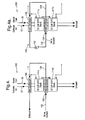
- a prior art solid-oxide fuel cell stack 10 contains a plurality of individual fuel cells (not visible in FIG. 1 ) arranged in flow parallel and electrical series, as is well known in the fuel cell art.
- FIG. 1a shows an alternate prior art multiple-substack arrangement having fuel cell sub-stacks 10' wherein, like stack 10 in FIG. 1 , each substack contains a plurality of fuel cells arranged in parallel flow.
- Substacks 10' are arranged in parallel flow pneumatic flow relative to each other and may be arranged electrically in series (as shown), in parallel, or controlled independently.
- Cathode air 12 enters stack 10, 10' at cathode inlet 14 and, after flowing across all of the individual cathode surfaces in the stack, exits the stack as spent air 16 at cathode air outlet 18.
- Fuel gas 20, for example, hydrogen and carbon monoxide from a hydrocarbon reformer (not shown) enters stack 10, 10' at anode inlet 22 and, after flowing across all of the individual anode surfaces in the stack, exits the stack as spent fuel gas 24 at anode outlet 26.
- the cathode air is pre-heated before entering the stack, and the fuel gas is also preheated or relatively hot as delivered from the reformer. Both gases, as they flow through the stack, undergo substantial heating, which heat when discharged to the environment as shown in FIG. 1 represents a significant thermodynamic loss and consequent fuel inefficiency. Further, as the gases are progressively heated within the stack, very substantial thermal stresses can be created which can lead to short working lifetimes of stress-sensitive components in the fuel cells.
- Example 1 An SOFC stack configured in accordance with FIG. 1 was operated at a current of 0.9 amps/cm 2 . With a temperature differential across the stack of 150°C (inlet temperature 650°C, outlet temperature 800°C), the stack produced 4810 watts of electricity at 0.74 volts/cell, fuel utilization was 43%, stack efficiency was 21.8%, and an additional 1136 watts of heat was released within the stack.
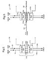
- a fuel cell stack 110 having a plurality of individual fuel cell elements for example, 60 cells as in prior art stack 10 is divided into a plurality of sub-stacks, for example, two sub-stacks 111a,111b each containing 30 fuel cell elements, the two sub-stacks being connected in series electrically.
- sub-stacks for example, two sub-stacks 111a,111b each containing 30 fuel cell elements, the two sub-stacks being connected in series electrically.
- Other numbers of sub-stacks are fully comprehended by the invention, and the numbers of fuel cells may or may not be distributed equally among the sub-stacks.
- the cathode exhaust 116a and anode exhaust 124a from first sub-stack 111a are collected and delivered to the respective inlets 114b,122b of sub-stack 111b.
- anode exhaust 124a has been passed over only 30 anode surfaces in sub-stack 111a and thus has a large remaining fuel content.
- cathode air exhaust 116a has a large remaining oxygen content.
- the mass flow of air and fuel gas through each cell is doubled with respect to stack 10, which has the advantage of reducing the temperature gradient across each sub-stack by providing additional cooling, thus reducing thermal stresses in the cells, substacks, and stacks.
- Example 2 An SOFC stack configured in accordance with FIG. 2 was operated at a current of 0.9 amps/cm 2 .
- Sub-stack 111a was operated with a temperature differential of 100°C (650°C inlet temperature, 750°C outlet temperature) and produced 2359 watts of electricity at 0.72 volts/cell. Fuel utilization was 21.8%, stack efficiency was 10.7%, and only 177 watts of heat were rejected into the stack. Note that this is a much lower fuel utilization and stack efficiency than for prior art stack 10.
- Sub-stack 11 1b had an inlet temperature of 750°C and an outlet temperature of 850°C.
- Sub-stack 111 b produced 2589 watts of electricity at 0.79 volts/cell. Fuel utilization was 28% and the stack efficiency was 15%. The reaction was slightly endothermic, requiring 138 watts of energy from the stack.
- FIG. 2 Advantages of the novel stack configuration in accordance with the invention ( FIG. 2 ) vs. the prior art configuration ( FIG. 1 ):
- a first heat exchanger 130 is installed in the flow paths of cathode exhaust 116a and anode exhaust 124a.
- Heat exchanger 130 may be a single three-way heat exchanger or two separate two-way heat exchangers, as is known in the heat exchanging art; for simplicity of presentation, heat exchanger 130 (and all other heat exchangers herein) is shown as a single unit.
- Tempered air or other coolant 132 is provided through a first side of exchanger 130 such that the exhaust streams of the first sub-stack are cooled with waste heat 134 moving to the environment or to be used productively elsewhere in the system.
- This arrangement can permit the two sub-stacks 111a,111b to operate at very similar temperatures, and to do so at the lower end of the viable temperature range. This is advantageous from a materials or durability standpoint although at some sacrifice in thermal and electrical efficiency.
- a second heat exchanger 140 is provided in the entrance streams of cathode air 12 and fuel gas 20. Some or all of waste heat 134 from first heat exchanger 130 is diverted through second heat exchanger 140 to additionally preheat cathode air 12 and fuel gas 20 prior to entry into first sub-stack 111a. Exhaust 134a from second heat exchanger 140 may be released to the environment or diverted for use productively elsewhere in the system.
- Example 2 clearly second sub-stack 11 1b performed better than first sub-stack 111a, largely because of higher operating temperature.
- First sub-stack 111a can be shown to operate better if the operating temperature is raised 100°C (which also raises the inlet and exhaust temperatures 100°C). Doing so changes the stack reaction from exothermic to slightly endothermic and improves stack efficiency. The net effect if run under adiabatic conditions would be a reduction in temperature gradient across sub-stack 111a.
- the efficiency of a series flow arrangement of sub-stacks 111a,111b can be improved if the sub-stacks are operated under similar thermal regimes, either by simply lowering the inlet temperature of the second sub-stack or by also raising the inlet temperature of the first sub-stack.
- a highly desirable effect of either approach is a reduction in stack thermal stress.
- the cooling system for heat exchangers 130,140 may readily be provided as a closed loop 150 including recirculation means such as a coolant pump or blower 152.
- a second stream 412 of cathode air 12 is mixed with cathode exhaust air 116a from first sub-stack 111a.
- Stream 412 is preferably tempered and metered to result in a cathode air inlet stream to second sub-stack 111b sufficient to decrease the temperature gradient across sub-stack 111b.
- This embodiment does not require either of heat exchangers 130,140 and their associated cooling system(s), but its effect is limited to lowering the temperature of the second sub-stack.
- a potential disadvantage of this embodiment is that a thermal imbalance is created between the temperatures of the cathode air and the fuel gas entering the second sub-stack, which can create undesirable mechanical stresses therein.
- stream 412 could be augmented with oxygen. This would be especially useful if multiple (more than 2) substacks were series flow connected in a substack module. Such gas tailoring or selection could impact the SOFC chemistry in downstream substacks as well as provide additional cooling as already noted.
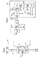
- a fuel cell stack module 500 in accordance with the invention comprises a first sub-stack 511a, a second sub-stack 511b, a precooler heat exchanger 540 ahead of the first sub-stack, and an intercooler heat exchanger 530 between the sub-stacks, which arrangement is substantially as described above.
- module 500 includes a temperature sensor T2 in the gas flowstream between precooler 540 and first sub-stack 511a to monitor the temperature of the cathode air 512 entering the sub-stack, which may be equal to the temperature of fuel gas 520 if their respective temperatures have been previously equalized to a temperature T1 during passage of the gases through opposite sides of an equalizer heat exchanger 502 outside module 500.
- a first coolant 580 may be passed through precooler 540 to adjust entry temperature T2 as desired.
- a temperature sensor T3 monitors the temperature of the gas exhausts from first sub-stack 511 a, and a temperature sensor T4 monitors the entry temperature of gases into second sub-stack 511b.
- a second coolant 582 may be passed through intercooler 530 to adjust entry temperature T4 as desired, which generally should be about the same as temperature T2.
- entry temperature T4 as desired, which generally should be about the same as temperature T2.
- Sensors T2 and T3 permit monitoring of the temperature change across first sub-stack 511a
- sensors T4 and T5 permit monitoring of the temperature change across second sub-stack 511 b.
- cathode air 12 is passed through a cathode air heat exchanger 590 in known fashion, which may be heated by exhaust gas at temperature T5, for example, and may be further tempered by addition of bypass air 592.
- Fuel gas 20 is supplied as by a hydrocarbon reformer 594 in known fashion.
- the temperature and flow rate of first coolant 580 is adjusted to provide a predetermined temperature T2 of cathode air and fuel gas at the entrance to first sub-stack 511a.
- the temperature and flow rate of second coolant 582 is adjusted to provide a predetermined temperature T4 of cathode air and fuel gas at the entrance to second sub-stack 511b.
- First and second coolants 580,582 may or may not be identical in substance, temperature, or flow rate.
- a coolant air plenum 596 may be used to supply both coolants 580,582 to module 500 from a common source at a common temperature, the individual flow rates of coolant being governed by a single proportional valve 598.
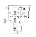
- a plurality of fuel cell stack modules 500 in this example three such modules, may be grouped together in an arrangement 600 having several legs of series sub-stacks connected in flow parallel to cathode air 12 and fuel gas 20. Because the optimal operating temperatures of the various first sub-stacks 511 a and second sub-stacks 511 b may differ slightly, the plurality of coolant flows 580,582 may be supplied from a common plenum 596 and individually flow-controlled by a plurality of control valves 597.
- substacks in the various embodiments, in accordance with the invention are shown connected electrically in series, it is understood that they could alternatively be connected electrically in parallel (controlling voltage or total current) or operated electrically independent (controlling voltage or current for each substack).
Landscapes
- Life Sciences & Earth Sciences (AREA)
- Sustainable Development (AREA)
- Engineering & Computer Science (AREA)
- Manufacturing & Machinery (AREA)
- Sustainable Energy (AREA)
- Chemical & Material Sciences (AREA)
- Chemical Kinetics & Catalysis (AREA)
- Electrochemistry (AREA)
- General Chemical & Material Sciences (AREA)
- Fuel Cell (AREA)
Claims (10)
- Brennstoffzellenstapel-Aufbau, der eine Vielzahl von Brennstoffzellen aufweist, die in eine Vielzahl von Teil-Stapel angeordnet sind,
wobei jeweilige Kathode- und Anode-Gas-Auslässe eines ersten Teil-Stapels in Serie mit jeweiligen Kathode- und Anode-Gas-Einlässen eines zweiten Teil-Stapels derart verbunden sind, dass Kathode-Abluft und Anode-Brennabgas aus dem ersten Teil-Stapel das jeweilige Oxidationsmittel und der Brennstoff für den zweiten Teil-Stapel sind,
der weiter aufweist einen ersten Wärmetauscher, der zwischen dem ersten Teil-Stapel und dem zweiten Teil-Stapel angeordnet ist, zum Ändern der Temperatur von zumindest einem der Kathode-Abluft und des Anode-Brennabgases vor deren Eintritt in den zweiten Teil-Stapel,
der weiter aufweist einen zweiten Wärmetauscher, der vor dem ersten Teil-Stapel angeordnet ist, zum Ändern der Temperatur von zumindest einem der Kathode-Luft und des Anode-Brenngases vor deren Eintritt in den ersten Teil-Stapel,
wobei der erste Wärmetauscher mit einem ersten Kühlmittel verbunden ist und der zweite Wärmetauscher mit einem zweiten Kühlmittel verbunden ist; und
wobei die Kombination des ersten Teil-Stapels, des zweiten Teil-Stapels und zumindest einem des ersten Wärmetauschers und des zweiten Wärmetauschers ein Brennstoffzellenstapel-Aufbau-Modul definiert, und
dadurch gekennzeichnet, dass
das Modul weiter aufweista) einen ersten Temperatursensor, der angrenzend an ein Einlassende des ersten Teil-Stapels angeordnet ist, zum Erfassen der Temperatur der Kathode-Luft, die in den ersten Teil-Stapel eintritt;b) einen zweiten Temperatursensor, der angrenzend an ein Auslassende des ersten Teil-Stapels angeordnet ist, zum Erfassen der Temperatur von zumindest einem der Kathode-Abluft und des Anode-Brennabgases, das/die den ersten Teil-Stapel verlässt/verlassen;c) einen dritten Temperatursensor, der angrenzend an ein Einslassende des zweiten Teil-Stapels angeordnet ist, zum Erfassen der Temperatur von zumindest einem der Kathode-Luft und des Anode-Brenngases, das/die in den zweiten Teil-Stapel eintritt/eintreten; undd) einen vierten Temperatursensor, der angrenzend an ein Auslassende des zweiten Teil-Stapels angeordnet ist, zum Erfassen der Temperatur von zumindest einem der Kathode-Abluft und des Anode-Brennabgases, das/die den zweiten Teil-Stapel verlässt/verlassen;
und wobei
die Temperatur und der Durchfluss des ersten Kühlmittels anpassbar sind, um eine vorgegebene Temperatur von Kathode-Luft und Brenngas am Eintritt zu dem ersten Teil-Stapel vorzusehen, und
die Temperatur und der Durchfluss des zweiten Kühlmittels anpassbar sind, um eine vorgegebene Temperatur von Kathode-Luft und Brenngas am Eintritt zu dem zweiten Teil-Stapel vorzusehen. - Brennstoffzellenstapel-Aufbau gemäß Anspruch 1, wobei die Brennstoffzellen Festoxidbrennstoffzellen sind.
- Brennstoffzellenstapel-Aufbau gemäß Anspruch 1, wobei die Vielzahl der Brennstoffzellen gleichmäßig zwischen zwei Teil-Stapeln aufgeteilt ist.
- Brennstoffzellen-Anordnung, die eine Vielzahl von einzelnen Brennstoffzellen-Aufbau-Modulen gemäß Anspruch 1 aufweist, wobei die Module im Fluss parallel zu einer gemeinsamen Zufuhr für Kathode-Luft und für Brenngas verbunden sind, und die Wärmetauscher mit einer gemeinsamen Zufuhr für Kühlmittel verbunden sind.
- Brennstoffzellen-Anordnung gemäß Anspruch 4, wobei der Durchfluss des Kühlmittels von der gemeinsamen Zufuhr zu jedem der Wärmetauscher unabhängig reguliert wird.
- Verfahren zum Betreiben eines Brennstoffzellenstapel-Aufbaus gemäß Anspruch 1 mit ersten und zweiten Teil-Stapeln, das die Schritte aufweist:a) Leiten von Kathode-Abluft von einem Kathode-Abluft-Auslass des ersten Teil-Stapels zu einem Kathode-Luft-Einlass des zweiten Teil-Stapels; undb) Leiten von Anode-Brennabgas von einem Anode-Brennabgas-Auslass des ersten Teil-Stapels zu einem Brenngas-Einlass des zweiten Teil-Stapels; und
Anpassen der Temperatur und des Durchflusses des ersten Kühlmittels, um eine vorgegebene Temperatur von Kathode-Luft und Brenngas an dem Eingang zu dem ersten Teil-Stapel vorzusehen; und
Anpassen der Temperatur und des Durchflusses des zweiten Kühlmittels, um eine vorgegebene Temperatur von Kathode-Luft und Brenngas an dem Eingang zu dem zweiten Teil-Stapel vorzusehen. - Verfahren gemäß Anspruch 6, das weiter die Schritte aufweist:a) Leiten eines ersten Kühlmittels durch eine erste Seite des ersten Wärmetauschers; undb) Leiten eines der Kathode-Abluft und des Anode-Brennabgases durch eine zweite Seite des ersten Wärmetauschers zwischen den Auslässen des ersten Teil-Stapels und den Einlässen des zweiten Teil-Stapels.
- Verfahren gemäß Anspruch 7, das weiter die Schritte aufweist:a) Leiten eines zweiten Kühlmittels durch eine erste Seite des zweiten Wärmetauschers; undb) Leiten von zumindest einem der Kathode-Luft und des Anode-Brenngases durch eine zweite Seite des zweiten Wärmetauschers vor deren Eintritt in den ersten Teil-Stapel.
- Verfahren gemäß Anspruch 8, wobei die erste Seite des ersten Wärmetauschers und die erste Seite des zweiten Wärmetauschers in Serie derart verbunden sind, dass die ersten und zweiten Kühlmittel dieselben sind, und derart, dass Kühlmittel, das den ersten Wärmetauscher verlässt, durch den zweiten Wärmetauscher geleitet wird.
- Verfahren gemäß Anspruch 9, das den weiteren Schritt aufweist eines Steuerns der Durchflüsse und Temperaturen der ersten und zweiten Kühlmittel derart, dass ein erster Betriebstemperaturgradient durch den ersten Teil-Stapel gleich einem zweiten Betriebstemperaturgradient durch den zweiten Teil-Stapel ist.
Applications Claiming Priority (1)
| Application Number | Priority Date | Filing Date | Title |
|---|---|---|---|
| US11/046,251 US7615299B2 (en) | 2005-01-28 | 2005-01-28 | Method and apparatus for thermal, mechanical, and electrical optimization of a solid-oxide fuel cell stack |
Publications (2)
| Publication Number | Publication Date |
|---|---|
| EP1686643A1 EP1686643A1 (de) | 2006-08-02 |
| EP1686643B1 true EP1686643B1 (de) | 2009-08-12 |
Family
ID=36061352
Family Applications (1)
| Application Number | Title | Priority Date | Filing Date |
|---|---|---|---|
| EP06075099A Expired - Lifetime EP1686643B1 (de) | 2005-01-28 | 2006-01-17 | Verfahren und Vorrichtung zur thermischen, mechanischen und elektrischen Optimierung eines Festoxydbrennstoffzellenstapels |
Country Status (4)
| Country | Link |
|---|---|
| US (1) | US7615299B2 (de) |
| EP (1) | EP1686643B1 (de) |
| AT (1) | ATE439688T1 (de) |
| DE (1) | DE602006008361D1 (de) |
Cited By (3)
| Publication number | Priority date | Publication date | Assignee | Title |
|---|---|---|---|---|
| DE102014219888A1 (de) * | 2014-10-01 | 2016-05-25 | Robert Bosch Gmbh | Brennstoffzellensystem und Verfahren zum Betreiben eines Brennstoffzellensystems mit erhöhtem Wirkungsgrad |
| DE102016200208A1 (de) * | 2016-01-11 | 2017-07-13 | Volkswagen Ag | Brennstoffzellensystem mit einem Common-Rail-System zur Anbindung mehrerer Brennstoffzellenstapel sowie Fahrzeug mit einem solchen Brennstoffzellensystem |
| RU2777834C2 (ru) * | 2018-03-15 | 2022-08-11 | Афл Лист Гмбх | Модульная система топливных элементов и способ разогрева системы топливных элементов с несколькими модулями |
Families Citing this family (35)
| Publication number | Priority date | Publication date | Assignee | Title |
|---|---|---|---|---|
| JPH07117647B2 (ja) * | 1992-05-25 | 1995-12-18 | シーメンス アクチエンゲゼルシヤフト | 走査対物レンズ |
| JP5185504B2 (ja) * | 2006-03-03 | 2013-04-17 | 本田技研工業株式会社 | 燃料電池システムおよびその運転方法 |
| EP1926166A1 (de) * | 2006-11-22 | 2008-05-28 | Vaillant GmbH | Brennstoffzellenheizgerät |
| US20100040914A1 (en) * | 2006-12-29 | 2010-02-18 | Sitaram Ramaswamy | Fuel-cascaded fuel cell stacks with decoupled power outputs |
| DE102007054291B4 (de) * | 2007-10-02 | 2015-02-26 | Diehl Aerospace Gmbh | Verfahren zum Bereitstellen von Energie und Energieversorgungseinheit dafür |
| DE102008033986B4 (de) * | 2008-07-21 | 2016-07-21 | Sunfire Gmbh | Brennstoffzellensystem mit zwei in Serie geschalteten Brennstoffzellenstapeln und Verfahren zum Betreiben eines solchen Brennstoffzellensystems |
| US8062799B2 (en) | 2008-08-19 | 2011-11-22 | Fuelcell Energy, Inc. | High-efficiency dual-stack molten carbonate fuel cell system |
| WO2010066463A1 (en) * | 2008-12-12 | 2010-06-17 | Ezelleron Gmbh | Fuel cell system with circular stack |
| KR20100114686A (ko) * | 2009-04-16 | 2010-10-26 | 삼성전자주식회사 | 복수 개의 발전 모듈들을 갖는 연료 전지 스택 및 연료 전지 시스템 |
| ES2391682T3 (es) * | 2009-05-22 | 2012-11-28 | Topsoe Fuel Cell A/S | Procedimiento de funcionamiento de un conjunto modular de apilamiento de pilas de combustible conectadas en serie |
| DE102009031774B4 (de) | 2009-06-30 | 2012-02-02 | Fraunhofer-Gesellschaft zur Förderung der angewandten Forschung e.V. | Hochtemperaturbrennstoffzellensystem |
| EP2458035A1 (de) | 2010-01-21 | 2012-05-30 | Alstom Technology Ltd | Verfahren zum Belüften einer Elektrolysezelle zur Aluminiumproduktion |
| US8889306B2 (en) * | 2010-02-16 | 2014-11-18 | The Boeing Company | Modularized electrochemical cell system |
| DE102011077695A1 (de) * | 2011-06-17 | 2012-12-20 | Siemens Aktiengesellschaft | Elektrischer Energiespeicher |
| US9234286B2 (en) * | 2012-05-04 | 2016-01-12 | Alstom Technology Ltd | Recycled pot gas pot distribution |
| JP5981379B2 (ja) * | 2013-03-29 | 2016-08-31 | 日本特殊陶業株式会社 | 燃料電池 |
| DE102013211730A1 (de) * | 2013-06-20 | 2014-12-24 | Deutsches Zentrum für Luft- und Raumfahrt e.V. | Brennstoffzellensystem und Verfahren zum Betreiben eines Brennstoffzellensystems |
| US10256496B2 (en) | 2014-07-01 | 2019-04-09 | General Electric Company | Power generation systems and methods utilizing cascaded fuel cells |
| US9608284B2 (en) | 2014-07-30 | 2017-03-28 | Microsoft Technology Licensing, Llc | Dynamically controlled heat exchange for cascading startup of fuel cell grids |
| JP6556440B2 (ja) * | 2014-11-19 | 2019-08-07 | 東京瓦斯株式会社 | 燃料電池システム |
| GB201501491D0 (en) * | 2015-01-29 | 2015-03-18 | Lg Fuel Cell Systems Inc | Method and apparatus for thermal control in a fuel cell |
| WO2017037938A1 (ja) * | 2015-09-04 | 2017-03-09 | 日産自動車株式会社 | 燃料電池システム及び燃料電池制御方法 |
| JP6163525B2 (ja) * | 2015-09-30 | 2017-07-12 | 東京瓦斯株式会社 | 燃料電池システム |
| NO345296B1 (en) * | 2016-07-14 | 2020-11-30 | Zeg Power As | Method and power plant comprising a Solid Oxide Fuel Cell (SOFC) for production of electrical energy and H2 gas |
| KR20190058582A (ko) | 2016-11-04 | 2019-05-29 | 니뽄 도쿠슈 도교 가부시키가이샤 | 전기 화학 반응 셀 스택 |
| US10854899B2 (en) | 2016-11-04 | 2020-12-01 | Cummins Enterprise Llc | Power generation system using cascaded fuel cells and associated methods thereof |
| CN111033847B (zh) * | 2017-08-14 | 2021-03-16 | 日产自动车株式会社 | 燃料电池系统以及燃料电池系统的制冷剂流量估计方法 |
| AT521068B1 (de) * | 2018-03-15 | 2020-11-15 | Avl List Gmbh | Modulares Brennstoffzellensystem und Verfahren zum Aufheizen eines Brennstoffzellensystems mit mehreren Modulen |
| US20200212461A1 (en) * | 2019-01-02 | 2020-07-02 | The Boeing Company | Systems and Methods for Increasing Solid Oxide Fuel Cell Efficiency |
| DE102019207117A1 (de) * | 2019-05-16 | 2020-11-19 | Robert Bosch Gmbh | Brennstoffzellensystem mit zwei Brennstoffzelleneinheiten die unabhängig voneinander betrieben werden können |
| CN110808387A (zh) * | 2019-10-21 | 2020-02-18 | 深圳市氢蓝时代动力科技有限公司 | 一种氢燃料电池的供气方法、氢燃料电池与发动机 |
| DE102019133717B4 (de) * | 2019-12-10 | 2021-10-28 | Sunfire Gmbh | Integrierte Hocheffizienz-Brennstoffzellenstapelanordnung |
| CN114039065B (zh) * | 2021-11-10 | 2025-05-06 | 海卓动力(青岛)能源科技有限公司 | 一种燃料电池热电联供系统及控制方法 |
| CN116093398B (zh) * | 2022-12-26 | 2025-09-16 | 东方电气(成都)氢燃料电池科技有限公司 | 一种燃料电池串联系统及调节方法 |
| DE102024210510A1 (de) * | 2024-10-31 | 2026-04-30 | Robert Bosch Gesellschaft mit beschränkter Haftung | Brennstoffzellenmodul und Brennstoffzellenanlage |
Family Cites Families (10)
| Publication number | Priority date | Publication date | Assignee | Title |
|---|---|---|---|---|
| JPS59149670A (ja) * | 1983-02-01 | 1984-08-27 | Toshiba Corp | 燃料電池発電装置 |
| JPH06101348B2 (ja) * | 1985-03-19 | 1994-12-12 | 三洋電機株式会社 | 燃料電池の温度制御装置 |
| US5413878A (en) * | 1993-10-28 | 1995-05-09 | The United States Of America As Represented By The Department Of Energy | System and method for networking electrochemical devices |
| JP3564742B2 (ja) | 1994-07-13 | 2004-09-15 | トヨタ自動車株式会社 | 燃料電池発電装置 |
| US5518828A (en) * | 1994-07-21 | 1996-05-21 | Bechtel Group, Inc. | Thermal integration of an air-cooled fuel cell stack |
| US6186254B1 (en) * | 1996-05-29 | 2001-02-13 | Xcelliss Fuel Cell Engines Inc. | Temperature regulating system for a fuel cell powered vehicle |
| US6033794A (en) * | 1997-12-10 | 2000-03-07 | The United States Of America As Represented By The United States Department Of Energy | Multi-stage fuel cell system method and apparatus |
| DE19857398B4 (de) * | 1998-12-12 | 2010-07-08 | GM Global Technology Operations, Inc., Detroit | Brennstoffzellensystem, insbesondere für elektromotorisch angetriebene Fahrzeuge |
| US20040081872A1 (en) * | 2002-10-28 | 2004-04-29 | Herman Gregory S. | Fuel cell stack with heat exchanger |
| DE10256281A1 (de) | 2002-12-03 | 2004-06-24 | Daimlerchrysler Ag | Brenstoffzellensystem mit vorteilhafter Stackverschaltung |
-
2005
- 2005-01-28 US US11/046,251 patent/US7615299B2/en not_active Expired - Fee Related
-
2006
- 2006-01-17 DE DE602006008361T patent/DE602006008361D1/de not_active Expired - Lifetime
- 2006-01-17 AT AT06075099T patent/ATE439688T1/de not_active IP Right Cessation
- 2006-01-17 EP EP06075099A patent/EP1686643B1/de not_active Expired - Lifetime
Cited By (3)
| Publication number | Priority date | Publication date | Assignee | Title |
|---|---|---|---|---|
| DE102014219888A1 (de) * | 2014-10-01 | 2016-05-25 | Robert Bosch Gmbh | Brennstoffzellensystem und Verfahren zum Betreiben eines Brennstoffzellensystems mit erhöhtem Wirkungsgrad |
| DE102016200208A1 (de) * | 2016-01-11 | 2017-07-13 | Volkswagen Ag | Brennstoffzellensystem mit einem Common-Rail-System zur Anbindung mehrerer Brennstoffzellenstapel sowie Fahrzeug mit einem solchen Brennstoffzellensystem |
| RU2777834C2 (ru) * | 2018-03-15 | 2022-08-11 | Афл Лист Гмбх | Модульная система топливных элементов и способ разогрева системы топливных элементов с несколькими модулями |
Also Published As
| Publication number | Publication date |
|---|---|
| DE602006008361D1 (de) | 2009-09-24 |
| EP1686643A1 (de) | 2006-08-02 |
| US7615299B2 (en) | 2009-11-10 |
| US20060172176A1 (en) | 2006-08-03 |
| ATE439688T1 (de) | 2009-08-15 |
Similar Documents
| Publication | Publication Date | Title |
|---|---|---|
| US7615299B2 (en) | Method and apparatus for thermal, mechanical, and electrical optimization of a solid-oxide fuel cell stack | |
| US8142943B2 (en) | Solid oxide fuel cell column temperature equalization by internal reforming and fuel cascading | |
| US6033794A (en) | Multi-stage fuel cell system method and apparatus | |
| US8822090B2 (en) | Internally reforming fuel cell assembly with staged fuel flow and selective catalyst loading for improved temperature uniformity and efficiency | |
| EP2559090B1 (de) | Wärmeverwaltung in einem brennstoffzellenstapel | |
| RU2531912C2 (ru) | Комбинированные схемы потоков в пакете топливных элементов или в пакете электролитических элементов | |
| US20100304261A1 (en) | Fuel cell design with an integrated heat exchanger and gas humidification unit | |
| JP2013527564A5 (de) | ||
| US20070111054A1 (en) | Cascaded fuel cell system | |
| EP2254182B1 (de) | Betriebsverfahren für eine in Reihe geschaltete Brennstoffzellenstapelmoduleinheit | |
| US6926985B2 (en) | Fuel cell stack | |
| EP2005509A2 (de) | Sofc-wärmeverwaltung über direktinjektion | |
| US20040265675A1 (en) | Fuel Cell Flow Field Design | |
| EP2643876B1 (de) | Gleichstrom-/gegenstrombrennstoffzelle oder elektrolysezelle | |
| AU2004203393A1 (en) | Methodology and apparatus for supply of reactant fluids to and purging of product and inert fluids from cells of fuel cell stack | |
| US7381491B2 (en) | Maximizing PEM fuel cell power plant system efficiency at optimum system pressure | |
| JP2928251B2 (ja) | 内部改質を行う燃料電池 | |
| EP3602662B1 (de) | System für festoxidbrennstoffzellen mit gestufter brennstoffzufuhr | |
| US7211342B2 (en) | Fuel cell system with regenerative bed | |
| HK1188516A (en) | Co-flow / counter-flow fuel cell or electrolysis cell |
Legal Events
| Date | Code | Title | Description |
|---|---|---|---|
| PUAI | Public reference made under article 153(3) epc to a published international application that has entered the european phase |
Free format text: ORIGINAL CODE: 0009012 |
|
| AK | Designated contracting states |
Kind code of ref document: A1 Designated state(s): AT BE BG CH CY CZ DE DK EE ES FI FR GB GR HU IE IS IT LI LT LU LV MC NL PL PT RO SE SI SK TR |
|
| AX | Request for extension of the european patent |
Extension state: AL BA HR MK YU |
|
| 17P | Request for examination filed |
Effective date: 20070202 |
|
| 17Q | First examination report despatched |
Effective date: 20070305 |
|
| AKX | Designation fees paid |
Designated state(s): AT BE BG CH CY CZ DE DK EE ES FI FR GB GR HU IE IS IT LI LT LU LV MC NL PL PT RO SE SI SK TR |
|
| 17Q | First examination report despatched |
Effective date: 20070305 |
|
| GRAP | Despatch of communication of intention to grant a patent |
Free format text: ORIGINAL CODE: EPIDOSNIGR1 |
|
| GRAS | Grant fee paid |
Free format text: ORIGINAL CODE: EPIDOSNIGR3 |
|
| GRAA | (expected) grant |
Free format text: ORIGINAL CODE: 0009210 |
|
| AK | Designated contracting states |
Kind code of ref document: B1 Designated state(s): AT BE BG CH CY CZ DE DK EE ES FI FR GB GR HU IE IS IT LI LT LU LV MC NL PL PT RO SE SI SK TR |
|
| REG | Reference to a national code |
Ref country code: GB Ref legal event code: FG4D |
|
| REG | Reference to a national code |
Ref country code: CH Ref legal event code: EP |
|
| REG | Reference to a national code |
Ref country code: IE Ref legal event code: FG4D |
|
| REF | Corresponds to: |
Ref document number: 602006008361 Country of ref document: DE Date of ref document: 20090924 Kind code of ref document: P |
|
| LTIE | Lt: invalidation of european patent or patent extension |
Effective date: 20090812 |
|
| PG25 | Lapsed in a contracting state [announced via postgrant information from national office to epo] |
Ref country code: IS Free format text: LAPSE BECAUSE OF FAILURE TO SUBMIT A TRANSLATION OF THE DESCRIPTION OR TO PAY THE FEE WITHIN THE PRESCRIBED TIME-LIMIT Effective date: 20091212 Ref country code: SE Free format text: LAPSE BECAUSE OF FAILURE TO SUBMIT A TRANSLATION OF THE DESCRIPTION OR TO PAY THE FEE WITHIN THE PRESCRIBED TIME-LIMIT Effective date: 20090812 Ref country code: AT Free format text: LAPSE BECAUSE OF FAILURE TO SUBMIT A TRANSLATION OF THE DESCRIPTION OR TO PAY THE FEE WITHIN THE PRESCRIBED TIME-LIMIT Effective date: 20090812 Ref country code: LT Free format text: LAPSE BECAUSE OF FAILURE TO SUBMIT A TRANSLATION OF THE DESCRIPTION OR TO PAY THE FEE WITHIN THE PRESCRIBED TIME-LIMIT Effective date: 20090812 Ref country code: ES Free format text: LAPSE BECAUSE OF FAILURE TO SUBMIT A TRANSLATION OF THE DESCRIPTION OR TO PAY THE FEE WITHIN THE PRESCRIBED TIME-LIMIT Effective date: 20091123 Ref country code: FI Free format text: LAPSE BECAUSE OF FAILURE TO SUBMIT A TRANSLATION OF THE DESCRIPTION OR TO PAY THE FEE WITHIN THE PRESCRIBED TIME-LIMIT Effective date: 20090812 |
|
| NLV1 | Nl: lapsed or annulled due to failure to fulfill the requirements of art. 29p and 29m of the patents act | ||
| PG25 | Lapsed in a contracting state [announced via postgrant information from national office to epo] |
Ref country code: NL Free format text: LAPSE BECAUSE OF FAILURE TO SUBMIT A TRANSLATION OF THE DESCRIPTION OR TO PAY THE FEE WITHIN THE PRESCRIBED TIME-LIMIT Effective date: 20090812 Ref country code: SI Free format text: LAPSE BECAUSE OF FAILURE TO SUBMIT A TRANSLATION OF THE DESCRIPTION OR TO PAY THE FEE WITHIN THE PRESCRIBED TIME-LIMIT Effective date: 20090812 Ref country code: PL Free format text: LAPSE BECAUSE OF FAILURE TO SUBMIT A TRANSLATION OF THE DESCRIPTION OR TO PAY THE FEE WITHIN THE PRESCRIBED TIME-LIMIT Effective date: 20090812 Ref country code: LV Free format text: LAPSE BECAUSE OF FAILURE TO SUBMIT A TRANSLATION OF THE DESCRIPTION OR TO PAY THE FEE WITHIN THE PRESCRIBED TIME-LIMIT Effective date: 20090812 |
|
| PG25 | Lapsed in a contracting state [announced via postgrant information from national office to epo] |
Ref country code: BG Free format text: LAPSE BECAUSE OF FAILURE TO SUBMIT A TRANSLATION OF THE DESCRIPTION OR TO PAY THE FEE WITHIN THE PRESCRIBED TIME-LIMIT Effective date: 20091112 Ref country code: PT Free format text: LAPSE BECAUSE OF FAILURE TO SUBMIT A TRANSLATION OF THE DESCRIPTION OR TO PAY THE FEE WITHIN THE PRESCRIBED TIME-LIMIT Effective date: 20091212 |
|
| PG25 | Lapsed in a contracting state [announced via postgrant information from national office to epo] |
Ref country code: EE Free format text: LAPSE BECAUSE OF FAILURE TO SUBMIT A TRANSLATION OF THE DESCRIPTION OR TO PAY THE FEE WITHIN THE PRESCRIBED TIME-LIMIT Effective date: 20090812 Ref country code: DK Free format text: LAPSE BECAUSE OF FAILURE TO SUBMIT A TRANSLATION OF THE DESCRIPTION OR TO PAY THE FEE WITHIN THE PRESCRIBED TIME-LIMIT Effective date: 20090812 Ref country code: RO Free format text: LAPSE BECAUSE OF FAILURE TO SUBMIT A TRANSLATION OF THE DESCRIPTION OR TO PAY THE FEE WITHIN THE PRESCRIBED TIME-LIMIT Effective date: 20090812 Ref country code: CZ Free format text: LAPSE BECAUSE OF FAILURE TO SUBMIT A TRANSLATION OF THE DESCRIPTION OR TO PAY THE FEE WITHIN THE PRESCRIBED TIME-LIMIT Effective date: 20090812 |
|
| PG25 | Lapsed in a contracting state [announced via postgrant information from national office to epo] |
Ref country code: SK Free format text: LAPSE BECAUSE OF FAILURE TO SUBMIT A TRANSLATION OF THE DESCRIPTION OR TO PAY THE FEE WITHIN THE PRESCRIBED TIME-LIMIT Effective date: 20090812 |
|
| PLBE | No opposition filed within time limit |
Free format text: ORIGINAL CODE: 0009261 |
|
| STAA | Information on the status of an ep patent application or granted ep patent |
Free format text: STATUS: NO OPPOSITION FILED WITHIN TIME LIMIT |
|
| PG25 | Lapsed in a contracting state [announced via postgrant information from national office to epo] |
Ref country code: BE Free format text: LAPSE BECAUSE OF FAILURE TO SUBMIT A TRANSLATION OF THE DESCRIPTION OR TO PAY THE FEE WITHIN THE PRESCRIBED TIME-LIMIT Effective date: 20090812 |
|
| 26N | No opposition filed |
Effective date: 20100517 |
|
| PG25 | Lapsed in a contracting state [announced via postgrant information from national office to epo] |
Ref country code: MC Free format text: LAPSE BECAUSE OF NON-PAYMENT OF DUE FEES Effective date: 20100131 |
|
| REG | Reference to a national code |
Ref country code: CH Ref legal event code: PL |
|
| PG25 | Lapsed in a contracting state [announced via postgrant information from national office to epo] |
Ref country code: GR Free format text: LAPSE BECAUSE OF FAILURE TO SUBMIT A TRANSLATION OF THE DESCRIPTION OR TO PAY THE FEE WITHIN THE PRESCRIBED TIME-LIMIT Effective date: 20091113 Ref country code: CH Free format text: LAPSE BECAUSE OF NON-PAYMENT OF DUE FEES Effective date: 20100131 Ref country code: LI Free format text: LAPSE BECAUSE OF NON-PAYMENT OF DUE FEES Effective date: 20100131 |
|
| PG25 | Lapsed in a contracting state [announced via postgrant information from national office to epo] |
Ref country code: IE Free format text: LAPSE BECAUSE OF NON-PAYMENT OF DUE FEES Effective date: 20100117 |
|
| PG25 | Lapsed in a contracting state [announced via postgrant information from national office to epo] |
Ref country code: IT Free format text: LAPSE BECAUSE OF FAILURE TO SUBMIT A TRANSLATION OF THE DESCRIPTION OR TO PAY THE FEE WITHIN THE PRESCRIBED TIME-LIMIT Effective date: 20090812 |
|
| PG25 | Lapsed in a contracting state [announced via postgrant information from national office to epo] |
Ref country code: CY Free format text: LAPSE BECAUSE OF FAILURE TO SUBMIT A TRANSLATION OF THE DESCRIPTION OR TO PAY THE FEE WITHIN THE PRESCRIBED TIME-LIMIT Effective date: 20090812 |
|
| PG25 | Lapsed in a contracting state [announced via postgrant information from national office to epo] |
Ref country code: HU Free format text: LAPSE BECAUSE OF FAILURE TO SUBMIT A TRANSLATION OF THE DESCRIPTION OR TO PAY THE FEE WITHIN THE PRESCRIBED TIME-LIMIT Effective date: 20100213 Ref country code: LU Free format text: LAPSE BECAUSE OF NON-PAYMENT OF DUE FEES Effective date: 20100117 |
|
| PG25 | Lapsed in a contracting state [announced via postgrant information from national office to epo] |
Ref country code: TR Free format text: LAPSE BECAUSE OF FAILURE TO SUBMIT A TRANSLATION OF THE DESCRIPTION OR TO PAY THE FEE WITHIN THE PRESCRIBED TIME-LIMIT Effective date: 20090812 |
|
| PGFP | Annual fee paid to national office [announced via postgrant information from national office to epo] |
Ref country code: DE Payment date: 20140129 Year of fee payment: 9 |
|
| PGFP | Annual fee paid to national office [announced via postgrant information from national office to epo] |
Ref country code: FR Payment date: 20140117 Year of fee payment: 9 |
|
| PGFP | Annual fee paid to national office [announced via postgrant information from national office to epo] |
Ref country code: GB Payment date: 20140127 Year of fee payment: 9 |
|
| REG | Reference to a national code |
Ref country code: DE Ref legal event code: R119 Ref document number: 602006008361 Country of ref document: DE |
|
| GBPC | Gb: european patent ceased through non-payment of renewal fee |
Effective date: 20150117 |
|
| PG25 | Lapsed in a contracting state [announced via postgrant information from national office to epo] |
Ref country code: DE Free format text: LAPSE BECAUSE OF NON-PAYMENT OF DUE FEES Effective date: 20150801 Ref country code: GB Free format text: LAPSE BECAUSE OF NON-PAYMENT OF DUE FEES Effective date: 20150117 |
|
| REG | Reference to a national code |
Ref country code: FR Ref legal event code: ST Effective date: 20150930 |
|
| PG25 | Lapsed in a contracting state [announced via postgrant information from national office to epo] |
Ref country code: FR Free format text: LAPSE BECAUSE OF NON-PAYMENT OF DUE FEES Effective date: 20150202 |