EP1686074A1 - Receptacle, in particular refuse collecting receptacle, with a lid - Google Patents
Receptacle, in particular refuse collecting receptacle, with a lid Download PDFInfo
- Publication number
- EP1686074A1 EP1686074A1 EP06300065A EP06300065A EP1686074A1 EP 1686074 A1 EP1686074 A1 EP 1686074A1 EP 06300065 A EP06300065 A EP 06300065A EP 06300065 A EP06300065 A EP 06300065A EP 1686074 A1 EP1686074 A1 EP 1686074A1
- Authority
- EP
- European Patent Office
- Prior art keywords
- spring
- tray according
- lid
- tank
- cavity
- Prior art date
- Legal status (The legal status is an assumption and is not a legal conclusion. Google has not performed a legal analysis and makes no representation as to the accuracy of the status listed.)
- Granted
Links
Images
Classifications
-
- B—PERFORMING OPERATIONS; TRANSPORTING
- B65—CONVEYING; PACKING; STORING; HANDLING THIN OR FILAMENTARY MATERIAL
- B65F—GATHERING OR REMOVAL OF DOMESTIC OR LIKE REFUSE
- B65F1/00—Refuse receptacles; Accessories therefor
- B65F1/14—Other constructional features; Accessories
- B65F1/16—Lids or covers
- B65F1/1646—Lids or covers provided with means for mounting on receptacles, e.g. hinges
-
- B—PERFORMING OPERATIONS; TRANSPORTING
- B65—CONVEYING; PACKING; STORING; HANDLING THIN OR FILAMENTARY MATERIAL
- B65F—GATHERING OR REMOVAL OF DOMESTIC OR LIKE REFUSE
- B65F1/00—Refuse receptacles; Accessories therefor
- B65F1/14—Other constructional features; Accessories
- B65F2001/1653—Constructional features of lids or covers
- B65F2001/1661—Constructional features of lids or covers relating to noise reduction, e.g. during opening or closing
Definitions
- the present invention relates to a tray, including waste collection, comprising a vessel and a lid.
- Document FR-A-2 754 797 of the applicant company discloses a retarder device for a waste container lid, comprising a screw with a nut screwed on and, on either side of the nut, two coil springs exerting on the nut antagonistic forces, to oppose the rotation of the lid in one direction or the other, to avoid a sudden shock of the lid on the tank when closed or opened , and therefore reduce noise.
- the present invention aims in particular to make it simpler to achieve the function of slowing the lid when closing or opening.
- the slowing down of the lid when it is closed or opened can be obtained relatively simply, with a small number of pieces.
- the resistive member is mounted in the connection portion with a chosen angular position so that the spring undergoes substantially no torsional stress in the reference angular position, in which the lid is made with an upper rim of the bowl. an angle of, for example, between about 90 ° and 180 °, being preferably close to 135 °.
- the spring is a coil spring.
- the resistive member in particular the spring, comprises a first fixing portion arranged to be fixed on the connecting member.
- the connecting member may for example comprise a slot in which said first fastening portion of the resistant member is engaged, so as to be locked in rotation.
- the first attachment portion can be introduced into the slot with a possibility of axial displacement or not.
- the first fixing portion is formed by a curved rod, for example a U-shaped rod, connected to a coil of the spring.
- the resistive member in particular the spring, comprises a second fixing portion immobilized in the cavity of the connecting portion of the vessel.
- the second fixing portion may be formed by a rod connected to a coil of the spring, this rod being in particular substantially adjacent, at least over a certain length, to the turns of the spring.
- the cavity of the connecting portion of the tank preferably comprises a groove in which at least partially engages said rod.
- the tray comprises a hinge part, in particular of elongated shape, arranged to engage at least partially in the cavity of the connecting portion of the tank and to secure in a manner pivoting the cover to this connecting part.
- the hinge part engages at least partially through turns of the spring.
- the spring can be mounted in said cavity by being slightly compressed or not.
- the hinge part comprises at one end at least one elastically deformable tab, in particular two elastically deformable tabs, arranged to bear against a transverse rib of the lid.
- the connecting member may comprise an arm extending substantially perpendicularly to the axis of rotation of the cover.
- the vessel has a volume of at least about 300 liters, for example at least about 600 liters.
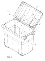
- FIG. 1 shows a bin 1 for collecting waste, comprising a tank 2 and a lid 3 mounted on the tank 2 pivotally about an axis of rotation X.
- Tray 1 can be of the rolling type or not.
- the tank 2 has for example a capacity greater than 300 liters, this capacity being in particular of about 660 liters.
- the tank 2 and the lid 3 are made by molding plastics material.
- the tank 2 has an upper flange 4 and two connecting portions 5 connecting to the upper flange 4, on a rear side 6 of the tank 2.
- each connecting portion 5 has a longitudinal portion 8 of X axis and two transverse portions 9 connecting the longitudinal portion 8 to the upper rim 4, on a rear side 6 of the tank 2.
- each longitudinal portion 8 has a substantially cylindrical outer shape of axis X and defines a gripping handle of the tank 2.
- the longitudinal portion 8 comprises a through cavity 10 substantially parallel to the axis X and in which is formed a longitudinal groove 11.
- the lid 3 comprises two pairs of transverse ribs 41 extending substantially perpendicular to the axis X, each rib 41 of a pair being disposed on either side of a corresponding connecting portion 5.
- One of the ribs 41 of each pair is provided with an orifice 42 intended to be arranged in the extension of the corresponding cavity 10.
- the cover 3 is pivotally mounted on each of the connecting parts 5 by means of a hinge part 13, which is for example made in one piece by molding a plastic material.
- the hinge piece 13 may, in a variant, not be made in one piece and have a plurality of assembled elements.
- the articulation piece 13 has an elongated shape along the X axis, with a rear portion 14, a central portion 15 and a front portion 16.
- the portions 14 to 16 comprise longitudinal ribs 17 intersecting and transverse ribs 18 each with a substantially disk-like shape.
- the transverse dimensions of the central portion 15 are greater than those of the rear portions 14 and 16 before.
- the hinge piece 13 is placed in the cavity 10 by introducing it through its front portion 16.
- the elastically deformable tabs 19 pass through the corresponding orifice 42 of the lid 3 while retracting and, at the end of assembly, resume their initial unstressed position, bearing on the corresponding rib 41 of the lid 3.
- the lid 3 is thus assembled on the connecting part 5.
- the tray 1 further comprises a connecting member 20 having an arm 21 extending substantially perpendicular to the axis X.
- the arm 21 is for example made of metal.
- the arm 21 has a substantially rectangular portion 22 intended to be fixed on the cover 3, for example by means of a screw-nut system.
- the connecting member 20 comprises a material bridge 24 connected to two opposite ends 25 to the arm 21.
- the material bridge 24 forms with the arm 21 a slot 26.
- the material bridge 24 is made by cutting and stamping the arm 21.
- the arm 21 has an opening 27 located in line with the material bridge 24.
- the connecting member 20 is secured to a resilient member 30 comprising a helical spring 31.
- the resistive member 30 comprises a first fastening portion 32 formed by a curved U-shaped rod which is connected to the turns 33 of the helical spring 31.
- This first attachment portion 32 is engaged in the slot 26 of the connecting member 20 so as to be locked in rotation.
- the resistive member 30 further comprises a second fixing portion 37 formed by a rod connected to the turns 33, at one end of the spring 31 opposite the first fixing portion 32.
- the rod 37 is substantially adjacent to the turns 33 over a certain length of the spring 31.
- the resistive member 30 is made in one piece.
- the resistive member 30 is put in place on the rear portion 14 of the articulation piece 13 which is engaged through the turns 33 of the spring.
- the articulation piece 13 can rotate freely relative to the resistive member 30.
- the resistive member 30 extends partially into the cavity 10, the rod 37 engaging in the groove 11 so as to be immobilized in rotation with respect to the connecting portion 5.
- the spring 31 is not compressed in a fm mounting, the first fixing portion 32 can move axially in the slot 26 of the connecting member 20.
- the resistive member 30 is mounted in the connecting portion 5 with an angular orientation chosen so that the spring 31 undergoes substantially no torsional stress in a reference angular position in which the cover 3 makes with the upper rim 4 the vessel 2 an angle of, for example, between about 90 ° and 180 °, preferably being close to 135 °.
- the spring 31 is arranged to work in torsion so as to oppose the rotation of the connecting member 20 about the X axis, in one direction or the other, from the reference angular position.
- the resistive member 30 may be attached in any other suitable manner to the connecting member 21 or to the connecting portion 5.
- the first fixing portion 32 of the resistive member 30 may for example be fixed to the connecting member 20 by a screw-nut system.
Abstract
Description
La présente invention a pour objet un bac, notamment de collecte de déchets, comportant une cuve et un couvercle.The present invention relates to a tray, including waste collection, comprising a vessel and a lid.
On connaît par le document FR-A-2 754 797 de la société déposante un dispositif ralentisseur pour couvercle de bac de collecte de déchets, comportant une vis avec un écrou vissé dessus et, de part et d'autre de l'écrou, deux ressorts hélicoïdaux exerçant sur l'écrou des forces antagonistes, permettant de s'opposer à la rotation du couvercle dans un sens ou dans l'autre, afm d'éviter un choc brutal du couvercle sur la cuve lors de sa fermeture ou de son ouverture, et donc de réduire les nuisances sonores.Document FR-A-2 754 797 of the applicant company discloses a retarder device for a waste container lid, comprising a screw with a nut screwed on and, on either side of the nut, two coil springs exerting on the nut antagonistic forces, to oppose the rotation of the lid in one direction or the other, to avoid a sudden shock of the lid on the tank when closed or opened , and therefore reduce noise.
La présente invention vise notamment à rendre plus simple la réalisation de la fonction de ralentissement du couvercle lors de sa fermeture ou de son ouverture.The present invention aims in particular to make it simpler to achieve the function of slowing the lid when closing or opening.
L'invention a ainsi pour objet un bac, notamment de collecte de déchets, comportant :
- une cuve,
- un couvercle monté pivotant par rapport à la cuve autour d'un axe de rotation,
- au moins une partie de liaison de la cuve et du couvercle, ladite partie de liaison comportant une cavité et formant de préférence une poignée de préhension,
- un organe de liaison fixé au couvercle pour lui transmettre un couple résistant,
- un organe résistant solidaire de l'organe de liaison et apte à être monté au moins partiellement dans la cavité de ladite partie de liaison de la cuve, l'organe résistant comportant au moins un ressort agencé pour travailler en torsion de manière à s'opposer à la rotation de l'organe de liaison autour dudit axe de rotation, dans un sens ou dans l'autre, à partir d'une position angulaire de référence de l'organe de liaison.
- a tank,
- a lid pivotally mounted relative to the bowl about an axis of rotation,
- at least one connecting portion of the vessel and the lid, said connecting portion having a cavity and preferably forming a gripping handle,
- a connecting member attached to the cover to transmit a resistive torque,
- a resistant member integral with the connecting member and adapted to be mounted at least partially in the cavity of said connecting portion of the vessel, the resilient member comprising at least one spring arranged to work in torsion so as to oppose the rotation of the connecting member about said axis of rotation, in one direction or the other, from a reference angular position of the connecting member.
Grâce à l'invention, le ralentissement du couvercle lors de sa fermeture ou de son ouverture peut être obtenu de manière relativement simple, avec un nombre réduit de pièces.Thanks to the invention, the slowing down of the lid when it is closed or opened can be obtained relatively simply, with a small number of pieces.
En particulier, il est possible d'utiliser un ressort unique travaillant en torsion, à la différence par exemple du dispositif décrit dans le document FR-A-2 754 797 qui utilise deux ressorts travaillant en traction ou en compression.In particular, it is possible to use a single spring working in torsion, unlike for example the device described in document FR-A-2 754 797 which uses two springs working in tension or in compression.
De préférence, l'organe résistant est monté dans la partie de liaison avec une position angulaire choisie de sorte que le ressort ne subit sensiblement aucune contrainte en torsion dans la position angulaire de référence, dans laquelle le couvercle fait avec un rebord supérieur de la cuve un angle compris par exemple entre environ 90° et 180°, étant de préférence voisin de 135°.Preferably, the resistive member is mounted in the connection portion with a chosen angular position so that the spring undergoes substantially no torsional stress in the reference angular position, in which the lid is made with an upper rim of the bowl. an angle of, for example, between about 90 ° and 180 °, being preferably close to 135 °.
De préférence, le ressort est un ressort hélicoïdal.Preferably, the spring is a coil spring.
Dans un exemple de mise en oeuvre de l'invention, l'organe résistant, notamment le ressort, comporte une première portion de fixation agencée pour être fixée sur l'organe de liaison.In an exemplary implementation of the invention, the resistive member, in particular the spring, comprises a first fixing portion arranged to be fixed on the connecting member.
L'organe de liaison peut par exemple comporter une fente dans laquelle ladite première portion de fixation de l'organe résistant est engagée, de manière à être bloquée en rotation.The connecting member may for example comprise a slot in which said first fastening portion of the resistant member is engaged, so as to be locked in rotation.
La première portion de fixation peut être introduite dans la fente avec une possibilité de déplacement axial ou non.The first attachment portion can be introduced into the slot with a possibility of axial displacement or not.
Avantageusement, la première portion de fixation est formée par une tige recourbée, par exemple une tige en U, se raccordant à une spire du ressort.Advantageously, the first fixing portion is formed by a curved rod, for example a U-shaped rod, connected to a coil of the spring.
Dans un exemple de mise en oeuvre de l'invention, l'organe résistant, notamment le ressort, comporte une deuxième portion de fixation immobilisée dans la cavité de la partie de liaison de la cuve.In an exemplary implementation of the invention, the resistive member, in particular the spring, comprises a second fixing portion immobilized in the cavity of the connecting portion of the vessel.
La deuxième portion de fixation peut être formée par une tige se raccordant à une spire du ressort, cette tige étant notamment sensiblement adjacente, au moins sur une certaine longueur, aux spires du ressort. La cavité de la partie de liaison de la cuve comporte de préférence une rainure dans laquelle s'engage au moins partiellement ladite tige.The second fixing portion may be formed by a rod connected to a coil of the spring, this rod being in particular substantially adjacent, at least over a certain length, to the turns of the spring. The cavity of the connecting portion of the tank preferably comprises a groove in which at least partially engages said rod.
Dans un exemple de mise en oeuvre de l'invention, le bac comporte une pièce d'articulation, notamment de forme allongée, agencée pour s'engager au moins partiellement dans la cavité de la partie de liaison de la cuve et pour solidariser de manière pivotante le couvercle à cette partie de liaison.In an exemplary implementation of the invention, the tray comprises a hinge part, in particular of elongated shape, arranged to engage at least partially in the cavity of the connecting portion of the tank and to secure in a manner pivoting the cover to this connecting part.
De préférence, la pièce d'articulation s'engage au moins partiellement à travers des spires du ressort.Preferably, the hinge part engages at least partially through turns of the spring.
Le ressort peut être monté dans ladite cavité en étant légèrement comprimé ou non.The spring can be mounted in said cavity by being slightly compressed or not.
Dans un exemple de mise en oeuvre de l'invention, la pièce d'articulation comporte à une extrémité au moins une patte élastiquement déformable, notamment deux pattes élastiquement déformables, agencées pour venir en appui contre une nervure transversale du couvercle.In an exemplary implementation of the invention, the hinge part comprises at one end at least one elastically deformable tab, in particular two elastically deformable tabs, arranged to bear against a transverse rib of the lid.
L'organe de liaison peut comporter un bras s'étendant sensiblement perpendiculairement à l'axe de rotation du couvercle.The connecting member may comprise an arm extending substantially perpendicularly to the axis of rotation of the cover.
Dans un exemple de mise en oeuvre de l'invention, la cuve présente un volume d'au moins 300 litres environ, par exemple d'au moins 600 litres environ.In an exemplary implementation of the invention, the vessel has a volume of at least about 300 liters, for example at least about 600 liters.
L'invention pourra être mieux comprise à la lecture de la description détaillée qui va suivre, d'un exemple de mise en oeuvre non limitatif de l'invention, et à l'examen du dessin annexé, sur lequel :
- la figure 1 représente, schématiquement et partiellement, un bac de collecte de déchets conforme à l'invention,
- la figure 2 est une vue en détail, schématique et partielle, de la cuve du bac de la figure 1, et
- la figure 3 représente, schématiquement et partiellement, en perspective, de manière isolée, certains éléments du bac de la figure 1.
- FIG. 1 represents, schematically and partially, a waste collection tank according to the invention,
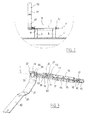
- FIG. 2 is a schematic partial view of the tank of the tank of FIG. 1, and
- FIG. 3 schematically and partially shows in perspective, in isolation, certain elements of the container of FIG. 1.
On a représenté sur la figure 1 un bac 1 de collecte de déchets, comportant une cuve 2 et un couvercle 3 monté sur la cuve 2 de manière pivotante autour d'un axe de rotation X.FIG. 1 shows a bin 1 for collecting waste, comprising a tank 2 and a lid 3 mounted on the tank 2 pivotally about an axis of rotation X.
Le bac 1 peut être du type roulant ou non.Tray 1 can be of the rolling type or not.
La cuve 2 présente par exemple une contenance supérieure à 300 litres, cette contenance étant notamment d'environ 660 litres.The tank 2 has for example a capacity greater than 300 liters, this capacity being in particular of about 660 liters.
Dans l'exemple considéré, la cuve 2 et le couvercle 3 sont réalisés par moulage de matière plastique.In the example considered, the tank 2 and the lid 3 are made by molding plastics material.
La cuve 2 présente un rebord supérieur 4 et deux parties de liaison 5 se raccordant au rebord supérieur 4, sur un côté arrière 6 de la cuve 2.The tank 2 has an upper flange 4 and two connecting
Comme illustré sur la figure 2, chaque partie de liaison 5 comporte une portion longitudinale 8 d'axe X et deux portions transversales 9 raccordant la portion longitudinale 8 au rebord supérieur 4, sur un côté arrière 6 de la cuve 2.As illustrated in FIG. 2, each connecting
Dans l'exemple considéré, chaque portion longitudinale 8 présente une forme extérieure sensiblement cylindrique d'axe X et définit une poignée de préhension de la cuve 2.In the example considered, each longitudinal portion 8 has a substantially cylindrical outer shape of axis X and defines a gripping handle of the tank 2.
La portion longitudinale 8 comporte une cavité traversante 10 sensiblement parallèle à l'axe X et dans laquelle est réalisée une rainure longitudinale 11.The longitudinal portion 8 comprises a through
Le couvercle 3 comporte deux paires de nervures transversales 41 s'étendant sensiblement perpendiculairement à l'axe X, chaque nervure 41 d'une paire étant disposée de part et d'autre d'une partie de liaison 5 correspondante.The lid 3 comprises two pairs of
L'une des nervures 41 de chaque paire est pourvue d'un orifice 42 destiné à être disposé dans le prolongement de la cavité 10 correspondante.One of the
Le couvercle 3 est monté pivotant sur chacune des parties de liaison 5 à l'aide d'une pièce d'articulation 13, laquelle est par exemple réalisée d'un seul tenant par moulage d'une matière plastique.The cover 3 is pivotally mounted on each of the connecting
La pièce d'articulation 13 peut, en variante, ne pas être réalisée d'un seul tenant et comporter une pluralité d'éléments assemblés.The
Comme illustré sur la figure 3, la pièce d'articulation 13 présente une forme allongée suivant l'axe X, avec une portion arrière 14, une portion centrale 15 et une portion avant 16.As illustrated in FIG. 3, the
Les portions 14 à 16 comportent des nervures longitudinales 17 s'entrecroisant et des nervures transversales 18 avec chacune une forme sensiblement en disque.The
Les dimensions transversales de la partie centrale 15 sont supérieures à celles des portions arrière 14 et avant 16.The transverse dimensions of the
Deux pattes élastiquement déformables 19 en regard sont prévues sur l'extrémité libre de la portion avant 16.Two elastically
La pièce d'articulation 13 est mise en place dans la cavité 10 en l'y introduisant par sa portion avant 16.The
Les pattes élastiquement déformables 19 franchissent l'orifice 42 correspondant du couvercle 3 en s'escamotant et, en fin de montage, reprennent leur position initiale, non contrainte, en venant en appui sur la nervure 41 correspondante du couvercle 3.The elastically
Le couvercle 3 est ainsi assemblé sur la partie de liaison 5.The lid 3 is thus assembled on the connecting
Le bac 1 comporte en outre un organe de liaison 20 comportant un bras 21 s'étendant sensiblement perpendiculairement à l'axe X.The tray 1 further comprises a connecting
Le bras 21 est par exemple réalisé en métal.The
Le bras 21 comporte une portion sensiblement rectangulaire 22 destinée à être fixée sur le couvercle 3, par exemple à l'aide d'un système vis-écrou.The
L'organe de liaison 20 comporte un pont de matière 24 se raccordant à deux extrémités opposées 25 au bras 21.The connecting
Le pont de matière 24 forme avec le bras 21 une fente 26.The
Dans l'exemple considéré, le pont de matière 24 est réalisé par découpe et emboutissage du bras 21.In the example considered, the
Le bras 21 comporte une ouverture 27 située au droit du pont de matière 24.The
L'organe de liaison 20 est solidarisé à un organe résistant 30 comportant un ressort hélicoïdal 31.The connecting
L'organe résistant 30 comporte une première portion de fixation 32 formée par une tige recourbée en U se raccordant aux spires 33 du ressort hélicoïdal 31.The
Cette première portion de fixation 32 est engagée dans la fente 26 de l'organe de liaison 20 de manière à être bloquée en rotation.This
Ainsi, lorsque l'organe de liaison 20 est déplacé en rotation autour de l'axe X, la première portion de fixation 32 accompagne ce déplacement en rotation.Thus, when the connecting
L'organe résistant 30 comporte en outre une deuxième portion de fixation 37 formée par une tige se raccordant aux spires 33, à une extrémité du ressort 31 opposée à la première portion de fixation 32.The
La tige 37 est sensiblement adjacente aux spires 33, sur une certaine longueur du ressort 31.The
Dans l'exemple considéré, l'organe résistant 30 est réalisé d'un seul tenant.In the example under consideration, the
L'organe résistant 30 est mis en place sur la portion arrière 14 de la pièce d'articulation 13 qui est engagée à travers les spires 33 du ressort.The
On note que la pièce d'articulation 13 peut tourner librement par rapport à l'organe résistant 30.It is noted that the
En fin de montage, l'organe résistant 30 s'étend en partie dans la cavité 10, la tige 37 s'engageant dans la rainure 11 de manière à être immobilisée en rotation par rapport à la partie de liaison 5.At the end of assembly, the
De préférence, le ressort 31 n'est pas comprimé en fm de montage, la première portion de fixation 32 pouvant se déplacer axialement dans la fente 26 de l'organe de liaison 20.Preferably, the
L'organe résistant 30 est monté dans la partie de liaison 5 avec une orientation angulaire choisie de manière à ce que le ressort 31 ne subisse sensiblement aucune contrainte en torsion dans une position angulaire de référence dans laquelle le couvercle 3 fait avec le rebord supérieur 4 de la cuve 2 un angle compris par exemple entre environ 90° et 180°, étant de préférence voisin de 135°.The
Le ressort 31 est agencé pour travailler en torsion de manière à s'opposer à la rotation de l'organe de liaison 20 autour de l'axe X, dans un sens ou dans l'autre, à partir de la position angulaire de référence.The
Ainsi, on obtient, en cas de chute du couvercle 3 lors de sa fermeture, un ralentissement de celui-ci relativement important pour qu'un choc entre le couvercle 3 et le rebord 4 de la cuve soit amorti.Thus, if the lid 3 falls during its closure, it is slowed down relatively high so that a shock between the lid 3 and the rim 4 of the tank is damped.
De même, lors de son ouverture, le couvercle qui se rabat contre une paroi latérale 40 de la cuve 2 est ralenti de sorte qu'il ne frappe pas violemment cette paroi latérale 40.Similarly, when it is opened, the lid which folds against a
Bien entendu, l'invention n'est pas limitée à l'exemple de mise en oeuvre qui vient d'être décrit.Of course, the invention is not limited to the implementation example which has just been described.
L'organe résistant 30 peut être fixé de toute autre manière appropriée à l'organe de liaison 21 ou à la partie de liaison 5.The
La première portion de fixation 32 de l'organe résistant 30 peut par exemple être fixée à l'organe de liaison 20 par un système vis-écrou.The
Claims (11)
Applications Claiming Priority (1)
| Application Number | Priority Date | Filing Date | Title |
|---|---|---|---|
| FR0550275A FR2881405B1 (en) | 2005-01-31 | 2005-01-31 | BAC, IN PARTICULAR A WASTE COLLECTION, HAVING A TANK AND A COVER |
Publications (2)
| Publication Number | Publication Date |
|---|---|
| EP1686074A1 true EP1686074A1 (en) | 2006-08-02 |
| EP1686074B1 EP1686074B1 (en) | 2016-09-21 |
Family
ID=34954393
Family Applications (1)
| Application Number | Title | Priority Date | Filing Date |
|---|---|---|---|
| EP06300065.7A Active EP1686074B1 (en) | 2005-01-31 | 2006-01-24 | Receptacle, in particular refuse collecting receptacle, with a lid |
Country Status (2)
| Country | Link |
|---|---|
| EP (1) | EP1686074B1 (en) |
| FR (1) | FR2881405B1 (en) |
Cited By (3)
| Publication number | Priority date | Publication date | Assignee | Title |
|---|---|---|---|---|
| EP2072420A1 (en) | 2007-12-20 | 2009-06-24 | Hellenic Environmental Systems Industry S.A. | Waste container lid controlling machanism |
| JP2018090364A (en) * | 2016-12-01 | 2018-06-14 | 新輝合成株式会社 | Trash box |
| CN114084549A (en) * | 2021-11-04 | 2022-02-25 | 上海拓牛智能科技有限公司 | Garbage bin opens and shuts and covers mechanism and intelligent garbage bin |
Citations (5)
| Publication number | Priority date | Publication date | Assignee | Title |
|---|---|---|---|---|
| DE1244648B (en) * | 1966-03-04 | 1967-07-13 | Streuber Sulo Eisenwerk F | Hinged lid, especially for large waste containers |
| CH517034A (en) * | 1971-05-24 | 1971-12-31 | Verzinkerei Zug Ag | Container with lid |
| CH532515A (en) * | 1971-12-13 | 1973-01-15 | Verwo Ag | Lid lifter on waste container to make it easier to open and close the lid of the container |
| DE3129285A1 (en) * | 1981-07-24 | 1983-06-09 | Gebr. Otto Kg, 5910 Kreuztal | Container lid, especially for large-scale refuse containers |
| FR2754797A1 (en) | 1996-10-18 | 1998-04-24 | Plastic Omnium Cie | Brake for rubbish bin cover |
-
2005
- 2005-01-31 FR FR0550275A patent/FR2881405B1/en not_active Expired - Fee Related
-
2006
- 2006-01-24 EP EP06300065.7A patent/EP1686074B1/en active Active
Patent Citations (5)
| Publication number | Priority date | Publication date | Assignee | Title |
|---|---|---|---|---|
| DE1244648B (en) * | 1966-03-04 | 1967-07-13 | Streuber Sulo Eisenwerk F | Hinged lid, especially for large waste containers |
| CH517034A (en) * | 1971-05-24 | 1971-12-31 | Verzinkerei Zug Ag | Container with lid |
| CH532515A (en) * | 1971-12-13 | 1973-01-15 | Verwo Ag | Lid lifter on waste container to make it easier to open and close the lid of the container |
| DE3129285A1 (en) * | 1981-07-24 | 1983-06-09 | Gebr. Otto Kg, 5910 Kreuztal | Container lid, especially for large-scale refuse containers |
| FR2754797A1 (en) | 1996-10-18 | 1998-04-24 | Plastic Omnium Cie | Brake for rubbish bin cover |
Cited By (3)
| Publication number | Priority date | Publication date | Assignee | Title |
|---|---|---|---|---|
| EP2072420A1 (en) | 2007-12-20 | 2009-06-24 | Hellenic Environmental Systems Industry S.A. | Waste container lid controlling machanism |
| JP2018090364A (en) * | 2016-12-01 | 2018-06-14 | 新輝合成株式会社 | Trash box |
| CN114084549A (en) * | 2021-11-04 | 2022-02-25 | 上海拓牛智能科技有限公司 | Garbage bin opens and shuts and covers mechanism and intelligent garbage bin |
Also Published As
| Publication number | Publication date |
|---|---|
| FR2881405B1 (en) | 2008-09-05 |
| EP1686074B1 (en) | 2016-09-21 |
| FR2881405A1 (en) | 2006-08-04 |
Similar Documents
| Publication | Publication Date | Title |
|---|---|---|
| FR2638722A1 (en) | BOX FOR STORING OBJECTS OF ELONGATE SHAPE, PARTICULARLY TOOLS SUCH AS HELICAL DRILLS, TAPS OR THE LIKE | |
| FR2560127A1 (en) | Armrest with hinged cover for vehicle | |
| EP1866510B1 (en) | Hinge device for an opening on a structure such as an insulated container door | |
| EP1686074B1 (en) | Receptacle, in particular refuse collecting receptacle, with a lid | |
| CH628389A5 (en) | DOOR INTERLOCKER. | |
| EP2942237A1 (en) | Device for anchoring a roof bar end for a motor vehicle provided with longitudinal roof bars | |
| EP2995386A1 (en) | Device for securing a glue applicator to a power screwdriver or drill | |
| FR3006656A3 (en) | MACHINE SUCH AS A SWING HANDLED LAWN MOWER | |
| FR2754797A1 (en) | Brake for rubbish bin cover | |
| EP0774424B1 (en) | Refuse collection container with means for braking the cover in its closing movement | |
| FR2960014A1 (en) | BAY ASSEMBLY | |
| EP1745827B1 (en) | Secure shoebinding on a gliding bord | |
| EP2588690A1 (en) | Lock for a motor vehicle door leaf | |
| FR2746338A1 (en) | STORAGE CABINET FOR LONG OBJECTS | |
| FR2927644A1 (en) | Retractable latch bolt for lock bucket of door leaf, has pivoting element pivotingly mounted inside free end so as to dampen impact of sliding surface against outer edge, while spring maintaining element in projection from sliding surface | |
| FR2752792A1 (en) | Motor vehicle glove box | |
| EP3023563B1 (en) | Door handle | |
| EP1732737B1 (en) | Tool for cutting hollow profiles | |
| EP3030460B1 (en) | Shelf for a motor vehicle boot | |
| EP4053369B1 (en) | System for pivoting a switchgear mounting and switchgear for installation comprising such a pivoting system | |
| EP0251844B1 (en) | Pivotable door handle | |
| EP1472427B1 (en) | Hinge arrangement for mounting a movable sash on a fixed structure | |
| EP0519141A1 (en) | Hinge with integral stop for vehicle doors or other closure members | |
| WO2014132006A1 (en) | Pivoting lid with noise limiter for waste collection bin | |
| FR3113919A1 (en) | DOOR LOCKING DEVICE |
Legal Events
| Date | Code | Title | Description |
|---|---|---|---|
| PUAI | Public reference made under article 153(3) epc to a published international application that has entered the european phase |
Free format text: ORIGINAL CODE: 0009012 |
|
| AK | Designated contracting states |
Kind code of ref document: A1 Designated state(s): AT BE BG CH CY CZ DE DK EE ES FI FR GB GR HU IE IS IT LI LT LU LV MC NL PL PT RO SE SI SK TR |
|
| AX | Request for extension of the european patent |
Extension state: AL BA HR MK YU |
|
| 17P | Request for examination filed |
Effective date: 20070202 |
|
| AKX | Designation fees paid |
Designated state(s): AT BE BG CH CY CZ DE DK EE ES FI FR GB GR HU IE IS IT LI LT LU LV MC NL PL PT RO SE SI SK TR |
|
| 17Q | First examination report despatched |
Effective date: 20070503 |
|
| GRAP | Despatch of communication of intention to grant a patent |
Free format text: ORIGINAL CODE: EPIDOSNIGR1 |
|
| GRAJ | Information related to disapproval of communication of intention to grant by the applicant or resumption of examination proceedings by the epo deleted |
Free format text: ORIGINAL CODE: EPIDOSDIGR1 |
|
| GRAP | Despatch of communication of intention to grant a patent |
Free format text: ORIGINAL CODE: EPIDOSNIGR1 |
|
| INTG | Intention to grant announced |
Effective date: 20160407 |
|
| INTG | Intention to grant announced |
Effective date: 20160414 |
|
| GRAS | Grant fee paid |
Free format text: ORIGINAL CODE: EPIDOSNIGR3 |
|
| GRAA | (expected) grant |
Free format text: ORIGINAL CODE: 0009210 |
|
| AK | Designated contracting states |
Kind code of ref document: B1 Designated state(s): AT BE BG CH CY CZ DE DK EE ES FI FR GB GR HU IE IS IT LI LT LU LV MC NL PL PT RO SE SI SK TR |
|
| REG | Reference to a national code |
Ref country code: GB Ref legal event code: FG4D Free format text: NOT ENGLISH |
|
| REG | Reference to a national code |
Ref country code: DE Ref legal event code: R081 Ref document number: 602006050333 Country of ref document: DE Owner name: PLASTIC OMNIUM SYSTEMES URBAINS, FR Free format text: FORMER OWNER: COMPAGNIE PLASTIC OMNIUM, LYON, FR |
|
| REG | Reference to a national code |
Ref country code: CH Ref legal event code: EP |
|
| REG | Reference to a national code |
Ref country code: AT Ref legal event code: REF Ref document number: 830848 Country of ref document: AT Kind code of ref document: T Effective date: 20161015 |
|
| REG | Reference to a national code |
Ref country code: IE Ref legal event code: FG4D Free format text: LANGUAGE OF EP DOCUMENT: FRENCH |
|
| REG | Reference to a national code |
Ref country code: DE Ref legal event code: R096 Ref document number: 602006050333 Country of ref document: DE |
|
| REG | Reference to a national code |
Ref country code: NL Ref legal event code: MP Effective date: 20160921 Ref country code: LT Ref legal event code: MG4D |
|
| REG | Reference to a national code |
Ref country code: FR Ref legal event code: PLFP Year of fee payment: 12 |
|
| PG25 | Lapsed in a contracting state [announced via postgrant information from national office to epo] |
Ref country code: LT Free format text: LAPSE BECAUSE OF FAILURE TO SUBMIT A TRANSLATION OF THE DESCRIPTION OR TO PAY THE FEE WITHIN THE PRESCRIBED TIME-LIMIT Effective date: 20160921 Ref country code: FI Free format text: LAPSE BECAUSE OF FAILURE TO SUBMIT A TRANSLATION OF THE DESCRIPTION OR TO PAY THE FEE WITHIN THE PRESCRIBED TIME-LIMIT Effective date: 20160921 |
|
| REG | Reference to a national code |
Ref country code: AT Ref legal event code: MK05 Ref document number: 830848 Country of ref document: AT Kind code of ref document: T Effective date: 20160921 |
|
| PG25 | Lapsed in a contracting state [announced via postgrant information from national office to epo] |
Ref country code: LV Free format text: LAPSE BECAUSE OF FAILURE TO SUBMIT A TRANSLATION OF THE DESCRIPTION OR TO PAY THE FEE WITHIN THE PRESCRIBED TIME-LIMIT Effective date: 20160921 Ref country code: NL Free format text: LAPSE BECAUSE OF FAILURE TO SUBMIT A TRANSLATION OF THE DESCRIPTION OR TO PAY THE FEE WITHIN THE PRESCRIBED TIME-LIMIT Effective date: 20160921 Ref country code: SE Free format text: LAPSE BECAUSE OF FAILURE TO SUBMIT A TRANSLATION OF THE DESCRIPTION OR TO PAY THE FEE WITHIN THE PRESCRIBED TIME-LIMIT Effective date: 20160921 Ref country code: GR Free format text: LAPSE BECAUSE OF FAILURE TO SUBMIT A TRANSLATION OF THE DESCRIPTION OR TO PAY THE FEE WITHIN THE PRESCRIBED TIME-LIMIT Effective date: 20161222 |
|
| PG25 | Lapsed in a contracting state [announced via postgrant information from national office to epo] |
Ref country code: EE Free format text: LAPSE BECAUSE OF FAILURE TO SUBMIT A TRANSLATION OF THE DESCRIPTION OR TO PAY THE FEE WITHIN THE PRESCRIBED TIME-LIMIT Effective date: 20160921 Ref country code: RO Free format text: LAPSE BECAUSE OF FAILURE TO SUBMIT A TRANSLATION OF THE DESCRIPTION OR TO PAY THE FEE WITHIN THE PRESCRIBED TIME-LIMIT Effective date: 20160921 |
|
| PG25 | Lapsed in a contracting state [announced via postgrant information from national office to epo] |
Ref country code: SK Free format text: LAPSE BECAUSE OF FAILURE TO SUBMIT A TRANSLATION OF THE DESCRIPTION OR TO PAY THE FEE WITHIN THE PRESCRIBED TIME-LIMIT Effective date: 20160921 Ref country code: IS Free format text: LAPSE BECAUSE OF FAILURE TO SUBMIT A TRANSLATION OF THE DESCRIPTION OR TO PAY THE FEE WITHIN THE PRESCRIBED TIME-LIMIT Effective date: 20170121 Ref country code: ES Free format text: LAPSE BECAUSE OF FAILURE TO SUBMIT A TRANSLATION OF THE DESCRIPTION OR TO PAY THE FEE WITHIN THE PRESCRIBED TIME-LIMIT Effective date: 20160921 Ref country code: PT Free format text: LAPSE BECAUSE OF FAILURE TO SUBMIT A TRANSLATION OF THE DESCRIPTION OR TO PAY THE FEE WITHIN THE PRESCRIBED TIME-LIMIT Effective date: 20170123 Ref country code: AT Free format text: LAPSE BECAUSE OF FAILURE TO SUBMIT A TRANSLATION OF THE DESCRIPTION OR TO PAY THE FEE WITHIN THE PRESCRIBED TIME-LIMIT Effective date: 20160921 Ref country code: BG Free format text: LAPSE BECAUSE OF FAILURE TO SUBMIT A TRANSLATION OF THE DESCRIPTION OR TO PAY THE FEE WITHIN THE PRESCRIBED TIME-LIMIT Effective date: 20161221 Ref country code: BE Free format text: LAPSE BECAUSE OF NON-PAYMENT OF DUE FEES Effective date: 20170131 Ref country code: CZ Free format text: LAPSE BECAUSE OF FAILURE TO SUBMIT A TRANSLATION OF THE DESCRIPTION OR TO PAY THE FEE WITHIN THE PRESCRIBED TIME-LIMIT Effective date: 20160921 Ref country code: PL Free format text: LAPSE BECAUSE OF FAILURE TO SUBMIT A TRANSLATION OF THE DESCRIPTION OR TO PAY THE FEE WITHIN THE PRESCRIBED TIME-LIMIT Effective date: 20160921 |
|
| REG | Reference to a national code |
Ref country code: DE Ref legal event code: R097 Ref document number: 602006050333 Country of ref document: DE |
|
| PG25 | Lapsed in a contracting state [announced via postgrant information from national office to epo] |
Ref country code: IT Free format text: LAPSE BECAUSE OF FAILURE TO SUBMIT A TRANSLATION OF THE DESCRIPTION OR TO PAY THE FEE WITHIN THE PRESCRIBED TIME-LIMIT Effective date: 20160921 |
|
| PLBE | No opposition filed within time limit |
Free format text: ORIGINAL CODE: 0009261 |
|
| STAA | Information on the status of an ep patent application or granted ep patent |
Free format text: STATUS: NO OPPOSITION FILED WITHIN TIME LIMIT |
|
| PG25 | Lapsed in a contracting state [announced via postgrant information from national office to epo] |
Ref country code: DK Free format text: LAPSE BECAUSE OF FAILURE TO SUBMIT A TRANSLATION OF THE DESCRIPTION OR TO PAY THE FEE WITHIN THE PRESCRIBED TIME-LIMIT Effective date: 20160921 |
|
| 26N | No opposition filed |
Effective date: 20170622 |
|
| REG | Reference to a national code |
Ref country code: CH Ref legal event code: PL |
|
| PG25 | Lapsed in a contracting state [announced via postgrant information from national office to epo] |
Ref country code: MC Free format text: LAPSE BECAUSE OF FAILURE TO SUBMIT A TRANSLATION OF THE DESCRIPTION OR TO PAY THE FEE WITHIN THE PRESCRIBED TIME-LIMIT Effective date: 20160921 |
|
| PG25 | Lapsed in a contracting state [announced via postgrant information from national office to epo] |
Ref country code: CH Free format text: LAPSE BECAUSE OF NON-PAYMENT OF DUE FEES Effective date: 20170131 Ref country code: LI Free format text: LAPSE BECAUSE OF NON-PAYMENT OF DUE FEES Effective date: 20170131 |
|
| REG | Reference to a national code |
Ref country code: IE Ref legal event code: MM4A |
|
| PG25 | Lapsed in a contracting state [announced via postgrant information from national office to epo] |
Ref country code: LU Free format text: LAPSE BECAUSE OF NON-PAYMENT OF DUE FEES Effective date: 20170124 Ref country code: SI Free format text: LAPSE BECAUSE OF FAILURE TO SUBMIT A TRANSLATION OF THE DESCRIPTION OR TO PAY THE FEE WITHIN THE PRESCRIBED TIME-LIMIT Effective date: 20160921 |
|
| REG | Reference to a national code |
Ref country code: FR Ref legal event code: PLFP Year of fee payment: 13 |
|
| REG | Reference to a national code |
Ref country code: BE Ref legal event code: MM Effective date: 20170131 |
|
| PG25 | Lapsed in a contracting state [announced via postgrant information from national office to epo] |
Ref country code: IE Free format text: LAPSE BECAUSE OF NON-PAYMENT OF DUE FEES Effective date: 20170124 |
|
| REG | Reference to a national code |
Ref country code: GB Ref legal event code: 732E Free format text: REGISTERED BETWEEN 20190110 AND 20190116 |
|
| REG | Reference to a national code |
Ref country code: DE Ref legal event code: R082 Ref document number: 602006050333 Country of ref document: DE Representative=s name: MAIWALD PATENTANWALTS- UND RECHTSANWALTSGESELL, DE Ref country code: DE Ref legal event code: R081 Ref document number: 602006050333 Country of ref document: DE Owner name: PLASTIC OMNIUM SYSTEMES URBAINS, FR Free format text: FORMER OWNER: COMPAGNIE PLASTIC OMNIUM, LYON, FR |
|
| PG25 | Lapsed in a contracting state [announced via postgrant information from national office to epo] |
Ref country code: HU Free format text: LAPSE BECAUSE OF FAILURE TO SUBMIT A TRANSLATION OF THE DESCRIPTION OR TO PAY THE FEE WITHIN THE PRESCRIBED TIME-LIMIT; INVALID AB INITIO Effective date: 20060124 |
|
| PG25 | Lapsed in a contracting state [announced via postgrant information from national office to epo] |
Ref country code: CY Free format text: LAPSE BECAUSE OF NON-PAYMENT OF DUE FEES Effective date: 20160921 |
|
| PG25 | Lapsed in a contracting state [announced via postgrant information from national office to epo] |
Ref country code: TR Free format text: LAPSE BECAUSE OF FAILURE TO SUBMIT A TRANSLATION OF THE DESCRIPTION OR TO PAY THE FEE WITHIN THE PRESCRIBED TIME-LIMIT Effective date: 20160921 |
|
| PGFP | Annual fee paid to national office [announced via postgrant information from national office to epo] |
Ref country code: GB Payment date: 20200123 Year of fee payment: 15 Ref country code: DE Payment date: 20200121 Year of fee payment: 15 |
|
| REG | Reference to a national code |
Ref country code: DE Ref legal event code: R119 Ref document number: 602006050333 Country of ref document: DE |
|
| GBPC | Gb: european patent ceased through non-payment of renewal fee |
Effective date: 20210124 |
|
| PG25 | Lapsed in a contracting state [announced via postgrant information from national office to epo] |
Ref country code: GB Free format text: LAPSE BECAUSE OF NON-PAYMENT OF DUE FEES Effective date: 20210124 Ref country code: DE Free format text: LAPSE BECAUSE OF NON-PAYMENT OF DUE FEES Effective date: 20210803 |
|
| PGFP | Annual fee paid to national office [announced via postgrant information from national office to epo] |
Ref country code: FR Payment date: 20230130 Year of fee payment: 18 |
|
| P01 | Opt-out of the competence of the unified patent court (upc) registered |
Effective date: 20230515 |