EP1684563A1 - Halteelement für einen Lüfter nach Art eines Klein-oder Kleinstlüfters - Google Patents
Halteelement für einen Lüfter nach Art eines Klein-oder Kleinstlüfters Download PDFInfo
- Publication number
- EP1684563A1 EP1684563A1 EP06006209A EP06006209A EP1684563A1 EP 1684563 A1 EP1684563 A1 EP 1684563A1 EP 06006209 A EP06006209 A EP 06006209A EP 06006209 A EP06006209 A EP 06006209A EP 1684563 A1 EP1684563 A1 EP 1684563A1
- Authority
- EP
- European Patent Office
- Prior art keywords
- retaining element
- fan
- element according
- extension
- circuit board
- Prior art date
- Legal status (The legal status is an assumption and is not a legal conclusion. Google has not performed a legal analysis and makes no representation as to the accuracy of the status listed.)
- Granted
Links
Images


Classifications
-
- H—ELECTRICITY
- H05—ELECTRIC TECHNIQUES NOT OTHERWISE PROVIDED FOR
- H05K—PRINTED CIRCUITS; CASINGS OR CONSTRUCTIONAL DETAILS OF ELECTRIC APPARATUS; MANUFACTURE OF ASSEMBLAGES OF ELECTRICAL COMPONENTS
- H05K7/00—Constructional details common to different types of electric apparatus
- H05K7/20—Modifications to facilitate cooling, ventilating, or heating
- H05K7/20009—Modifications to facilitate cooling, ventilating, or heating using a gaseous coolant in electronic enclosures
- H05K7/20136—Forced ventilation, e.g. by fans
- H05K7/20172—Fan mounting or fan specifications
-
- F—MECHANICAL ENGINEERING; LIGHTING; HEATING; WEAPONS; BLASTING
- F04—POSITIVE - DISPLACEMENT MACHINES FOR LIQUIDS; PUMPS FOR LIQUIDS OR ELASTIC FLUIDS
- F04D—NON-POSITIVE-DISPLACEMENT PUMPS
- F04D29/00—Details, component parts, or accessories
- F04D29/60—Mounting; Assembling; Disassembling
- F04D29/601—Mounting; Assembling; Disassembling specially adapted for elastic fluid pumps
-
- G—PHYSICS
- G06—COMPUTING OR CALCULATING; COUNTING
- G06F—ELECTRIC DIGITAL DATA PROCESSING
- G06F1/00—Details not covered by groups G06F3/00 - G06F13/00 and G06F21/00
- G06F1/16—Constructional details or arrangements
- G06F1/18—Packaging or power distribution
- G06F1/181—Enclosures
-
- G—PHYSICS
- G06—COMPUTING OR CALCULATING; COUNTING
- G06F—ELECTRIC DIGITAL DATA PROCESSING
- G06F1/00—Details not covered by groups G06F3/00 - G06F13/00 and G06F21/00
- G06F1/16—Constructional details or arrangements
- G06F1/20—Cooling means
Definitions
- the invention relates to a holding element for mounting a fan in the manner of a small or micro fan on a circuit board.
- An attachment and holder as known from EP 0 822 337 A2, is complicated and complicated in construction and assembly, which makes their use in mass production difficult and in many cases too expensive.
- the invention has for its object to provide a holding element available that is simple in its construction and cheap to manufacture and that allows secure attachment of such a fan on a circuit board.
- a holding element is particularly small and simple and is therefore suitable for very small fans in order to secure them to a printed circuit board.
- the dimensionally stable, deformable barrier extension allows, in conjunction with the insertion extension, a fast, automatable fastening, eg in an assembly line of mass production.
- FIG. 1 shows an inventive retaining element 1 for fastening a component 2
- FIG. 2 shows the retaining element 1 on a component 2
- FIG. 3 shows the retaining element 1 locked to a printed circuit board 5.
- the holding element 1 has a holding element base plate 10, holding formations 11 and locking extensions 17.
- the Halterungsausform Institute 11 are used to hold the device 2 and for fixing the device 2 in its position to the holding element 1 (see also Fig. 2).
- the Halterungsausform Institute 11, which provide the component 2 support surfaces 13 are formed by stop tabs 12 and mounting tabs 14.
- the component 2 can be glued or welded to the support formations 11 or, as in the example shown (FIG. 2), by means of openings 15 punched in the fastening tabs 14, which overlap with corresponding openings on the component 2, and with a tubular rivet which passes through the openings 24 are connected as fastening means 16.
- the fastening tabs 14 may also have latching lugs or the like for mechanical connection, which can latch with corresponding edges or projections on the component.
- the four locking extensions 17 are used for fastening the retaining element 1 to a support 4, in the example on a printed circuit board 5 (see Fig. 3).
- the Arretianssfortaries 17 cooperate with a receiving opening 20 so that a permanent connection by positive engagement is formed when the Arret michsfort engines be deformed in the substantially slot-shaped receiving openings 20 of the circuit board 5.
- a locking extension 17 is formed flat as a tab and has to its projecting from the holding element 1 end 18 out two widening inclined surfaces 19 (see Fig. 1).
- the holding element 1 has a contacting penetration 21, through which contacting projections 22 in the form of wire pins pass from the component 2 to the printed circuit board 5 ( see Fig. 2 and Fig. 3).
- the holding element 1 also has two position fixing extensions 23, which engage in receiving openings 25 formed in the printed circuit board 5. This causes the holding element 1 is held in two of three spatial directions in its position relative to the circuit board 5. As a result, mechanical forces are transmitted from the component or from the holding element 1 to the printed circuit board 5. An automatic assembly is possible and simplified by the self-adjustment to the circuit board.
- Such a holding element 1 is particularly suitable for heavy components 2, since the holding element base plate 10 forms a stable base for receiving the component 2.
- FIG. 4 shows a further, particularly advantageous embodiment of a holding element 1, 1a, 1b according to the invention for fastening a component
- FIG. 5 shows the holding element 1, 1a, 1b on a component 2
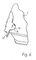
- FIG. 6 shows the holding element 1, 1a, FIG. 1b viewed from another angle.
- the holding element 1, 1a, 1b has an insertion extension 30, which is provided for insertion into an opening 33, which opening 33 is formed in the example by a passage 34 in the fan 3.
- the Einsteckfortsatz 30 is formed as a many barbs 40 having Einpresssteg 36 (also called claw web). This is pressed with force in the opening 33 (passage 34) on the fan 3 and forms a firm connection between the fan and the holding element (see also Fig. 6).
- the holding element 1 further has a dimensionally stable deformable locking extension 31, which is formed by a solder tab 37, which allows electrical contacting by soldering or by a crimp connection.
- the locking extension 31 (soldering tab 37) is designed so that it causes a positive connection of the holding element 1 with the fan 3 together with the insertion extension 30 in the opening 33 (passage 34) of the component 2 (fan 3).
- the locking extension 31 is slightly bent in its blocking end position on the fan 3 to its contact surface 39, from which it runs away (see Fig. 5).
- the projection 35 of the fan 3 engages behind and inhibits the withdrawal of the Einsteckfortsatzes 30 from the opening 33. Due to the double securing by locking extension 31 and barbs 40, an unwanted solution of the retaining element 1a, 1b is excluded from the fan 3.
- the holding element For fastening the holding element 1a, 1b to a carrier, for example a printed circuit board, the holding element has a fastening extension 32, which is soldered to the printed circuit board.
- the connection to a circuit board or the like can also be done by deformation of the attachment extension 32 in an opening of the circuit board.
- the holding element 1, 1a, 1b is preferably made entirely of metal and thus serves via the solder tab 37 and the attachment extension 32 for the electrical connection of the fan 3 with lines on a printed circuit board. As a result, otherwise necessary additional contacts and mounting and contacting steps can be saved.
- the holding element 1 is integrally formed from sheet metal, wherein the insertion extension 30, the locking projection 31 and the attachment extension 32 are made by punching and Abkröpfen of a metal sheet, whereby the insertion extension 30 and the locking extension 31 bearing abutment surface (39) at right angles to the base 38th of the holding element 1 away.
Landscapes
- Engineering & Computer Science (AREA)
- Theoretical Computer Science (AREA)
- Physics & Mathematics (AREA)
- General Engineering & Computer Science (AREA)
- General Physics & Mathematics (AREA)
- Human Computer Interaction (AREA)
- Microelectronics & Electronic Packaging (AREA)
- Power Engineering (AREA)
- Computer Hardware Design (AREA)
- Thermal Sciences (AREA)
- Mechanical Engineering (AREA)
- Structures Of Non-Positive Displacement Pumps (AREA)
- Mounting Components In General For Electric Apparatus (AREA)
- Cooling Or The Like Of Electrical Apparatus (AREA)
Abstract
Description
- Die Erfindung betrifft ein Halteelement für die Halterung eines Lüfters nach Art eines Klein- oder Kleinstlüfters auf einer Leiterplatte.
- In der Elektronik wir immer häufiger eine direkte Kühlung einzelner wärmeerzeugender Elemente direkt an oder auf einer Leiterplatte gewünscht. Moderne Klein- und Kleinstlüfter können diese Anforderungen erfüllen, da sie schon mit Außenabmessungen von nur 25 x 25 x 8 mm, 40 x 40 x 10 mm, 40 x 40 x 20 mm oder auch 60 x 60 x 15 mm hergestellt werden, um nur beispielhaft einige typische Abmessungen zu nennen. Solche kleinen Lüfter haben ein Gewicht etwa im Bereich von 5 bis 100 g. Problematisch für ihre Anwendung direkt auf einer Leiterplatte sind einmal die Montage selbst, und zum anderen die hierzu notwendigen Halterungen und Befestigungen.
- Eine Befestigung und Halterung, wie sie aus der EP 0 822 337 A2 bekannt ist, ist aufwändig und kompliziert in Aufbau und Montage, was ihre Anwendung in der Massenfertigung erschwert und in vielen Fällen zu teuer macht.
- Der Erfindung liegt die Aufgabe zugrunde, ein Halteelement zur Verfügung zu stellen, das einfach in seinem Aufbau und billig herzustellen ist und das eine sichere Befestigung eines solchen Lüfters auf einer Leiterplatte ermöglicht.
- Nach der Erfindung wird diese Aufgabe gelöst durch den Gegenstand des Anspruchs 1. Ein solches Halteelement ist besonders klein und einfach und eignet sich deshalb für sehr kleine Lüfter, um diese sicher an einer Leiterplatte zu befestigen. Der formstabil verformbare Sperrfortsatz ermöglicht in Verbindung mit dem Einsteckfortsatz eine schnelle, automatisierbare Befestigung, z.B. in einer Bestückungsstraße der Massenfertigung.
- Weitere Einzelheiten und vorteilhafte Weiterbildungen der Erfindung ergeben sich aus den im folgenden beschriebenen und in der Zeichnung dargestellten, in keiner Weise als Einschränkung der Erfindung zu verstehenden Ausführungsbeispielen, sowie aus den Unteransprüchen. Es zeigt:
- Fig. 1
- eine erste Ausführungsform eines Halteelements,
- Fig. 2
- das Halteelement der Fig. 1, befestigt an einem Bauelement,
- Fig. 3
- das Halteelement der Fig. 1 und 2, arretiert an einer Leiterplatte,
- Fig. 4
- eine zweite Ausführungsform eines erfindungsgemäßen Halteelements in rechter und linker Ausführung,
- Fig. 5
- die Halteelemente aus Fig. 4 am Bauelement, und
- Fig. 6
- ein Halteelement aus Fig. 5 aus einem anderen Winkel betrachtet.
- Die in den Figuren gleichen Bezugsziffern bezeichnen gleiche oder gleich wirkende Elemente.
- Fig. 1 zeigt ein erfindungsgemäßes Halteelement 1 zur Befestigung eines Bauelements 2, Fig. 2 zeigt das Halteelement 1 an einem Bauelement 2, und Fig. 3 zeigt das Halteelement 1 an einer Leiterplatte 5 arretiert.
- Das Halteelement 1 weist eine Halteelementgrundplatte 10, Halterungsausformungen 11 und Arretierungsfortsätze 17 auf.
- Die Halterungsausformungen 11 dienen zur Halterung des Bauelements 2 und zur Fixierung des Bauelements 2 in seiner Lage zum Halteelement 1 (siehe hierzu auch Fig. 2). Die Halterungsausformungen 11, die dem Bauelement 2 Abstützflächen 13 bieten, sind durch Anschlaglaschen 12 und Befestigungslaschen 14 gebildet. Das Bauelement 2 kann mit den Halterungsausformungen 11 verklebt oder verschweißt werden, oder wie im gezeigten Beispiel (Fig. 2) mittels in den Befestigungslaschen 14 gestanzter Öffnungen 15, welche sich mit entsprechenden Öffnungen am Bauelement 2 überdecken, und mit einer durch die Öffnungen durchgreifenden Rohrniete 24 als Befestigungsmittel 16 verbunden werden. Die Befestigungslaschen 14 können zur mechanischen Verbindung auch Rastnasen oder ähnliches aufweisen, welche mit entsprechenden Kanten oder Vorsprüngen am Bauelement verrasten können.
- Die vier Arretierungsfortsätze 17 dienen zur Befestigung des Halteelements 1 an einem Träger 4, im Beispiel an einer Leiterplatte 5 (vgl. Fig. 3).
- Die Arretierungsfortsätze 17 wirken mit einer Aufnahme-Öffnung 20 so zusammen, dass eine dauerhafte Verbindung durch Formschluss entsteht, wenn die Arretierungsfortsätze in den im Wesentlichen schlitzförmigen Aufnahme-Öffnungen 20 der Leiterplatte 5 verformt werden.
- Hierzu ist ein Arretierungsfortsatz 17 flach als Lasche ausgebildet und weist zu seinem vom Halteelement 1 wegragenden Ende 18 hin zwei breiter werdende Schrägflächen 19 auf (siehe Fig. 1). Durch diese Form wird auch ein Toleranzausgleich bezüglich der Dicke der Leiterplatte erreicht, da es immer zu einer spielfreien Verbindung zwischen Halteelement und Leiterplatte kommt.
- Damit eine elektrische Kontaktierung zwischen an dem Bauelement 2 und an der Leiterplatte 5 ausgebildeten Stromzuführungen oder Leitungen erfolgen kann, weist das Halteelement 1 einen Kontaktierungs-Durchgriff 21 auf, durch welchen Kontaktierungsfortsätze 22 in Form von Drahtstiften, von dem Bauelement 2 zur Leiterplatte 5 durchreichen (siehe Fig. 2 und Fig. 3).
- Das Halteelement 1 weist weiterhin zwei Lagefixierungsfortsätze 23 auf, welche in in der Leiterplatte 5 ausgebildete Aufnahmeöffnungen 25 eingreifen. Dies bewirkt, dass das Halteelement 1 in zwei von drei Raumrichtungen in seiner Lage relativ zur Leiterplatte 5 gehalten wird. Hierdurch werden auch mechanische Kräfte vom Bauelement bzw. vom Halteelement 1 auf die Leiterplatte 5 übertragen. Eine automatische Bestückung ist ermöglicht und vereinfacht durch die Selbstjustierung zur Leiterplatte.
- Durch die Ausgestaltung des Halteelements 1 ist es möglich, dieses einstückig aus Blech herzustellen, wobei die Halterungsausformung 11 und/oder der Arretierungsfortsatz 17 und/oder der Lagefixierungsfortsatz 23 insbesondere durch Ausstanzen und Abkröpfen aus einem Blech hergestellt wird.
- Ein solches Halteelement 1 eignet sich insbesondere auch für schwere Bauelemente 2, da die Halteelementgrundplatte 10 für die Aufnahme des Bauelements 2 eine stabile Basis bildet.
- Fig. 4 zeigt eine weitere, besonders vorteilhafte Ausgestaltung eines erfindungsgemäßen Halteelements 1, 1a, 1b zur Befestigung eines Bauelements, Fig. 5 zeigt das Halteelement 1, 1a, 1b an einem Bauelement 2, und Fig. 6 zeigt das Halteelement 1, 1a, 1b aus einem anderen Winkel betrachtet.
- Gezeigt ist eine rechte 1a und eine linke 1b Ausführungsform, zur Anbringung an zwei gegenüberliegenden Seiten eines Bauelements 2 (siehe hierzu auch Fig. 5).
- Das Halteelement 1, 1a, 1b weist einen Einsteckfortsatz 30 auf, welcher zur Einführung in eine Öffnung 33 vorgesehen ist, welche Öffnung 33 im Beispiel durch eine Durchführung 34 im Lüfter 3 ausgebildet ist. Der Einsteckfortsatz 30 ist als ein viele Widerhaken 40 aufweisender Einpresssteg 36 (auch Krallensteg genannt) ausgebildet. Dieser wird mit Kraftaufwand in die Öffnung 33 (Durchführung 34) am Lüfter 3 eingedrückt und bildet eine feste Verbindung zwischen Lüfter und Halteelement (siehe auch Fig. 6).
- Das Halteelement 1 verfügt weiterhin über einen formstabil verformbaren Sperrfortsatz 31, der durch eine Lötlasche 37 gebildet ist, welcher eine elektrische Kontaktierung durch Löten oder durch einen Crimpanschluss ermöglicht.
- Der Sperrfortsatz 31 (Lötlasche 37) ist so ausgestaltet, dass er zusammen mit dem Einsteckfortsatz 30 in der Öffnung 33 (Durchführung 34) des Bauelements 2 (Lüfter 3) eine formschlüssige Verbindung des Halteelements 1 mit dem Lüfter 3 bewirkt.
- Hierzu wird der Sperrfortsatz 31 in seiner sperrenden Endposition am Lüfter 3 zu seiner Anlagefläche 39, von welcher er weg verläuft, leicht abgebogen (siehe Fig. 5). Der Einsteckfortsatz 30 kann nun nicht mehr aus der Öffnung 33 im Lüfter 3 gezogen werden, da der Sperrfortsatz 31 den Vorsprung 35 des Lüfters 3 hintergreift und das Herausziehen des Einsteckfortsatzes 30 aus der Öffnung 33 hemmt. Durch die doppelte Sicherung durch Sperrfortsatz 31 und Widerhaken 40 ist eine ungewollte Lösung des Halteelements 1a, 1b vom Lüfter 3 ausgeschlossen.
- Zur Befestigung des Halteelements 1a, 1b an einem Träger, beispielsweise einer Leiterplatte, weist das Halteelement einen Befestigungsfortsatz 32 auf, welcher mit der Leiterplatte verlötet wird. Die Verbindung mit einer Leiterplatte oder dergleichen kann auch durch Verformung des Befestigungsfortsatzes 32 in einer Öffnung der Leiterplatte erfolgen.
- Das Halteelement 1, 1a, 1b besteht bevorzugt ganz aus Metall und dient so über die Lötlasche 37 und den Befestigungsfortsatz 32 zur elektrischen Verbindung des Lüfters 3 mit Leitungen auf einer Leiterplatte. Hierdurch werden sonst notwendige zusätzliche Kontakte und Befestigungs- und Kontaktierungsschritte eingespart.
- Das Halteelement 1 ist einstückig aus Blech ausgebildet, wobei der Einsteckfortsatz 30, der Sperrfortsatz 31 und der Befestigungsfortsatz 32 durch Ausstanzen und Abkröpfen aus einem Blech hergestellt sind, wodurch der Einsteckfortsatz 30 und die den Sperrfortsatz 31 tragende Anlagefläche (39) rechtwinklig von der Grundfläche 38 des Halteelements 1 weg verlaufen.
- Naturgemäß sind im Rahmen der Erfindung vielfache Abwandlungen möglich.
Claims (17)
- Halteelement zur Befestigung eines Lüfters (3) nach Art eines Klein- oder Kleinstlüfters auf einer Leiterplatte (5), welches Halteelement (1a, 1 b) einen Einsteckfortsatz aufweist, der zur Einführung in eine Öffnung (33) des Lüfters (3) ausgebildet ist,
wobei das Halteelement (1a, 1b) einen formstabil verformbaren Sperrfortsatz (31) aufweist, der so ausgestaltet ist, dass er zusammen mit dem Einsteckfortsatz (30) in der Öffnung (33) des Lüfters (3) eine formschlüssige Verbindung mit dem Lüfter (3) bewirkt, in der Weise, dass der Sperrfortsatz (31) eine Kante oder einen Vorsprung (35) des Lüfters (3) hintergreift, wobei das Halteelement (1a, 1 b) wenigstens einen Befestigungsfortsatz (32) zur Verbindung mit der Leiterplatte (5) aufweist. - Halteelement nach Anspruch 1, bei welchem der Einsteckfortsatz (30) mindestens einen Widerhaken (40) oder dergleichen aufweist.
- Halteelement nach Anspruch 1 oder 2, an welchem eine Lötlasche (37) vorgesehen ist.
- Halteelement nach Anspruch 3, bei welchem der Sperrfortsatz (31) durch die Lötlasche (37) gebildet ist.
- Halteelement nach einem der Ansprüche 1 bis 4, welches eine Grundfläche (38) aufweist, von welcher der Einsteckfortsatz (30) und eine den Sperrfortsatz (31) tragende Anlagefläche (39) im wesentlichen rechtwinklig weg verlaufen.
- Halteelement nach Anspruch 5, bei welchem der Sperrfortsatz (31) in einer sperrenden Lage am Lüfter (3) zu der Anlagefläche (39), von welcher er weg verläuft, leicht angewinkelt ist.
- Halteelement nach einem der Ansprüche 1 bis 6, welches mindestens teilweise aus Blech ausgebildet ist, wobei der Einsteckfortsatz (30) und / oder der Sperrfortsatz (31) und / oder der Befestigungsfortsatz (32), insbesondere durch Ausstanzen und Abkröpfen, aus diesem Blech hergestellt sind.
- Halteelement nach einem der Ansprüche 1 bis 7, welches mindestens teilweise aus Metall besteht, wobei die elektrische Verbindung zwischen Lüfter (3) und Leiterplatte (5) über das Halteelement (1a, 1b) an dessen Sperrfortsatz (31) und Befestigungsfortsatz (32) erfolgt.
- Halteelement nach einem der vorhergehenden Ansprüche, welches Halterungsausformungen (11) aufweist, die dazu ausgebildet sind, den Lüfter (3) in seiner Lage relativ zum Halteelement (1) zu fixieren,
und welches wenigstens einen Arretierungsfortsatz (17) aufweist, der dazu ausgebildet ist, mit einer Öffnung (20) der Leiterplatte (5) so zusammen zu wirken, dass er eine Arretierung des Halteelements (1) an der Leiterplatte (5) ermöglicht. - Halteelement nach Anspruch 9, bei welchem der Arretierungsfortsatz (17) flach, insbesondere in Form einer Lasche, ausgebildet ist, und sich in Richtung zu seinem vom Halteelement (1) wegragenden Ende (18) hin verbreitert.
- Halteelement nach Anspruch 9 oder 10, bei welchem eine Befestigungslasche (14) eine Öffnung (15) aufweist, welche im montierten Zustand mit einer entsprechenden Öffnung des Lüfters (3) fluchtet, so dass ein Befestigungsmittel (16) beide Öffnungen durchdringen kann.
- Halteelement nach Anspruch 11, bei welchem das Befestigungsmittel (16) als Rohrniet (24), Schraubenbefestigung oder dgl. ausgebildet ist.
- Halteelement nach einem der Ansprüche 9 bis 12, bei welchem die Befestigungslaschen (14) Rastnasen zur Verrastung mit entsprechenden Kanten oder Vorsprüngen des Lüfters (3) aufweisen.
- Halteelement nach einem der Ansprüche 9 bis 13, welches eine Kontaktierungs-Ausnehmung (21) aufweist, durch welche Kontaktelement (22) vom Lüfter (3) zur Leiterplatte (5) durchragen können.
- Halteelement nach einem der Ansprüche 9 bis 14, welches wenigstens einen Lagefixierungsfortsatz (23) aufweist, der zum Zusammenwirken mit der Leiterplatte (5) derart ausgebildet ist, dass das Halteelement (1) wenigstens in zwei von drei Raumrichtungen in seiner Lage relativ zur Leiterplatte (5) fixiert ist.
- Halteelement nach einem der Ansprüche 9 bis 15, welches mindestens teilweise aus Blech ausgebildet ist, wobei die Halterungsausformungen (11) und / oder der Arretierungsfortsatz (17) und / oder der Lagefixierungsfortsatz (23), insbesondere durch Ausstanzen und Abkröpfen, aus diesem Blech hergestellt sind.
- Halteelement nach einem der vorhergehenden Ansprüche, welches mit einem Klein- oder Kleinstlüfter (3) verbunden ist.
Applications Claiming Priority (2)
| Application Number | Priority Date | Filing Date | Title |
|---|---|---|---|
| DE20304718 | 2003-03-25 | ||
| EP04006638A EP1463397B1 (de) | 2003-03-25 | 2004-03-19 | Halteelement für einen Lüfter nach Art eines Klein- oder Kleinstlüfters |
Related Parent Applications (1)
| Application Number | Title | Priority Date | Filing Date |
|---|---|---|---|
| EP04006638A Division EP1463397B1 (de) | 2003-03-25 | 2004-03-19 | Halteelement für einen Lüfter nach Art eines Klein- oder Kleinstlüfters |
Publications (2)
| Publication Number | Publication Date |
|---|---|
| EP1684563A1 true EP1684563A1 (de) | 2006-07-26 |
| EP1684563B1 EP1684563B1 (de) | 2009-06-24 |
Family
ID=32404515
Family Applications (2)
| Application Number | Title | Priority Date | Filing Date |
|---|---|---|---|
| EP04006638A Expired - Lifetime EP1463397B1 (de) | 2003-03-25 | 2004-03-19 | Halteelement für einen Lüfter nach Art eines Klein- oder Kleinstlüfters |
| EP06006209A Expired - Lifetime EP1684563B1 (de) | 2003-03-25 | 2004-03-19 | Halteelement für einen Lüfter nach Art eines Klein-oder Kleinstlüfters |
Family Applications Before (1)
| Application Number | Title | Priority Date | Filing Date |
|---|---|---|---|
| EP04006638A Expired - Lifetime EP1463397B1 (de) | 2003-03-25 | 2004-03-19 | Halteelement für einen Lüfter nach Art eines Klein- oder Kleinstlüfters |
Country Status (3)
| Country | Link |
|---|---|
| EP (2) | EP1463397B1 (de) |
| AT (2) | ATE434924T1 (de) |
| DE (3) | DE202004004318U1 (de) |
Citations (4)
| Publication number | Priority date | Publication date | Assignee | Title |
|---|---|---|---|---|
| US5478221A (en) * | 1994-01-31 | 1995-12-26 | Lzr Electronics, Inc. | Miniature fan for printed circuit board |
| EP0755177A1 (de) * | 1995-07-21 | 1997-01-22 | Molex Incorporated | Abschirmdeckel mit zugehörigem Abschirmverfahren |
| EP0822337A2 (de) * | 1996-07-31 | 1998-02-04 | Papst-Motoren GmbH & Co. KG | Haltevorrichtung für elektrische Lüfter, insbesondere Kleinstlüfter |
| US6183214B1 (en) * | 1999-08-04 | 2001-02-06 | D-Link Corporation | Cooling fan mounting arrangement |
-
2004
- 2004-03-19 AT AT06006209T patent/ATE434924T1/de not_active IP Right Cessation
- 2004-03-19 DE DE202004004318U patent/DE202004004318U1/de not_active Expired - Lifetime
- 2004-03-19 DE DE502004009669T patent/DE502004009669D1/de not_active Expired - Lifetime
- 2004-03-19 EP EP04006638A patent/EP1463397B1/de not_active Expired - Lifetime
- 2004-03-19 EP EP06006209A patent/EP1684563B1/de not_active Expired - Lifetime
- 2004-03-19 AT AT04006638T patent/ATE434923T1/de not_active IP Right Cessation
- 2004-03-19 DE DE502004009638T patent/DE502004009638D1/de not_active Expired - Lifetime
Patent Citations (4)
| Publication number | Priority date | Publication date | Assignee | Title |
|---|---|---|---|---|
| US5478221A (en) * | 1994-01-31 | 1995-12-26 | Lzr Electronics, Inc. | Miniature fan for printed circuit board |
| EP0755177A1 (de) * | 1995-07-21 | 1997-01-22 | Molex Incorporated | Abschirmdeckel mit zugehörigem Abschirmverfahren |
| EP0822337A2 (de) * | 1996-07-31 | 1998-02-04 | Papst-Motoren GmbH & Co. KG | Haltevorrichtung für elektrische Lüfter, insbesondere Kleinstlüfter |
| US6183214B1 (en) * | 1999-08-04 | 2001-02-06 | D-Link Corporation | Cooling fan mounting arrangement |
Also Published As
| Publication number | Publication date |
|---|---|
| ATE434923T1 (de) | 2009-07-15 |
| EP1684563B1 (de) | 2009-06-24 |
| DE502004009669D1 (de) | 2009-08-06 |
| DE202004004318U1 (de) | 2004-05-27 |
| EP1463397A3 (de) | 2006-03-01 |
| ATE434924T1 (de) | 2009-07-15 |
| EP1463397B1 (de) | 2009-06-24 |
| EP1463397A2 (de) | 2004-09-29 |
| DE502004009638D1 (de) | 2009-08-06 |
Similar Documents
| Publication | Publication Date | Title |
|---|---|---|
| EP2846408B2 (de) | Elektrische Anschlussklemme | |
| EP1777720A1 (de) | Elektrisches Bauteil, insbesondere Relaisfassung, mit Federklemmen und Verfahren zu seiner Herstellung | |
| DE102009058825A1 (de) | Kontaktvorrichtung zum Befestigen an einer Leiterplatte, Verfahren zum Befestigen einer Kontaktvorrichtung an einer Leiterplatte und Leiterplatte | |
| DE102009042385A9 (de) | Multi Fork Einpresspin | |
| DE102016213019B3 (de) | Elektronische Baugruppe mit Thermosicherung und Verwendung der elektronischen Baugruppe für einen Elektromotor eines Verstellsystems oder -antriebs | |
| DE102017125505A1 (de) | Steckerbuchse für Leiterplatinen | |
| EP3378289B1 (de) | Leiterplatte zum mechanischen fixieren eines gehäuses | |
| DE102013216472A1 (de) | Elektrische Kontaktanordnung für einen Elektromotor und Verfahren zur Herstellung | |
| DE202010013758U1 (de) | Einlötkontaktanordnung | |
| DE19726856C1 (de) | Flachstecker für elektrische Steckverbindungen | |
| DE19731411A1 (de) | Haltevorrichtung für elektrische Lüfter, insbesondere Kleinstlüfter | |
| DE102016002821A1 (de) | Schaltkreis einer elektronischen Steuereinheit | |
| EP2200125B1 (de) | Geschirmter Steckverbinder | |
| DE202010018429U1 (de) | Betätigungseinrichtung für eine elektrische Anschlussklemme | |
| DE102006049070B4 (de) | Steckverbinder mit wenigstens einem Seitenelement | |
| EP1153460A1 (de) | Vorrichtung zur elektrischen und mechanischen verbindung von zwei leiterplatten | |
| EP1684563B1 (de) | Halteelement für einen Lüfter nach Art eines Klein-oder Kleinstlüfters | |
| DE102006061308A1 (de) | Halterung | |
| DE102010043495A1 (de) | Elektrisches Bauteil zur Oberflächenmontage | |
| DE102005010704B4 (de) | Federbuchse für Miniatur-Steckverbinder | |
| EP2018091A2 (de) | Bauteil mit Lötpin | |
| DE19842237B4 (de) | Befestigungsanordnung für eine Zusatzleiterplatte auf einer Mutterleiterplatte | |
| DE102019134369B4 (de) | Leadframe für Drahtbauteile mit Kulissenstruktur | |
| DE19900647C2 (de) | Verbundbauteil, insbesondere Gehäuse | |
| DE102017107470A1 (de) | Steckelement zur Verbindung an einer Leiterplatte mit durchkontaktierten Bohrungen |
Legal Events
| Date | Code | Title | Description |
|---|---|---|---|
| PUAI | Public reference made under article 153(3) epc to a published international application that has entered the european phase |
Free format text: ORIGINAL CODE: 0009012 |
|
| AC | Divisional application: reference to earlier application |
Ref document number: 1463397 Country of ref document: EP Kind code of ref document: P |
|
| AK | Designated contracting states |
Kind code of ref document: A1 Designated state(s): AT BE BG CH CY CZ DE DK EE ES FI FR GB GR HU IE IT LI LU MC NL PL PT RO SE SI SK TR |
|
| AX | Request for extension of the european patent |
Extension state: AL LT LV MK |
|
| 17P | Request for examination filed |
Effective date: 20060811 |
|
| AKX | Designation fees paid |
Designated state(s): AT BE BG CH CY CZ DE DK EE ES FI FR GB GR HU IE IT LI LU MC NL PL PT RO SE SI SK TR |
|
| 17Q | First examination report despatched |
Effective date: 20080812 |
|
| GRAP | Despatch of communication of intention to grant a patent |
Free format text: ORIGINAL CODE: EPIDOSNIGR1 |
|
| GRAS | Grant fee paid |
Free format text: ORIGINAL CODE: EPIDOSNIGR3 |
|
| GRAA | (expected) grant |
Free format text: ORIGINAL CODE: 0009210 |
|
| AC | Divisional application: reference to earlier application |
Ref document number: 1463397 Country of ref document: EP Kind code of ref document: P |
|
| AK | Designated contracting states |
Kind code of ref document: B1 Designated state(s): AT BE BG CH CY CZ DE DK EE ES FI FR GB GR HU IE IT LI LU MC NL PL PT RO SE SI SK TR |
|
| REG | Reference to a national code |
Ref country code: GB Ref legal event code: FG4D Free format text: NOT ENGLISH |
|
| REG | Reference to a national code |
Ref country code: CH Ref legal event code: EP |
|
| REG | Reference to a national code |
Ref country code: IE Ref legal event code: FG4D Free format text: LANGUAGE OF EP DOCUMENT: GERMAN |
|
| REF | Corresponds to: |
Ref document number: 502004009669 Country of ref document: DE Date of ref document: 20090806 Kind code of ref document: P |
|
| PG25 | Lapsed in a contracting state [announced via postgrant information from national office to epo] |
Ref country code: FI Free format text: LAPSE BECAUSE OF FAILURE TO SUBMIT A TRANSLATION OF THE DESCRIPTION OR TO PAY THE FEE WITHIN THE PRESCRIBED TIME-LIMIT Effective date: 20090624 |
|
| PG25 | Lapsed in a contracting state [announced via postgrant information from national office to epo] |
Ref country code: PL Free format text: LAPSE BECAUSE OF FAILURE TO SUBMIT A TRANSLATION OF THE DESCRIPTION OR TO PAY THE FEE WITHIN THE PRESCRIBED TIME-LIMIT Effective date: 20090624 Ref country code: SE Free format text: LAPSE BECAUSE OF FAILURE TO SUBMIT A TRANSLATION OF THE DESCRIPTION OR TO PAY THE FEE WITHIN THE PRESCRIBED TIME-LIMIT Effective date: 20090924 Ref country code: SI Free format text: LAPSE BECAUSE OF FAILURE TO SUBMIT A TRANSLATION OF THE DESCRIPTION OR TO PAY THE FEE WITHIN THE PRESCRIBED TIME-LIMIT Effective date: 20090624 |
|
| NLV1 | Nl: lapsed or annulled due to failure to fulfill the requirements of art. 29p and 29m of the patents act | ||
| PG25 | Lapsed in a contracting state [announced via postgrant information from national office to epo] |
Ref country code: EE Free format text: LAPSE BECAUSE OF FAILURE TO SUBMIT A TRANSLATION OF THE DESCRIPTION OR TO PAY THE FEE WITHIN THE PRESCRIBED TIME-LIMIT Effective date: 20090624 Ref country code: CZ Free format text: LAPSE BECAUSE OF FAILURE TO SUBMIT A TRANSLATION OF THE DESCRIPTION OR TO PAY THE FEE WITHIN THE PRESCRIBED TIME-LIMIT Effective date: 20090624 Ref country code: ES Free format text: LAPSE BECAUSE OF FAILURE TO SUBMIT A TRANSLATION OF THE DESCRIPTION OR TO PAY THE FEE WITHIN THE PRESCRIBED TIME-LIMIT Effective date: 20091005 |
|
| REG | Reference to a national code |
Ref country code: IE Ref legal event code: FD4D |
|
| PG25 | Lapsed in a contracting state [announced via postgrant information from national office to epo] |
Ref country code: SK Free format text: LAPSE BECAUSE OF FAILURE TO SUBMIT A TRANSLATION OF THE DESCRIPTION OR TO PAY THE FEE WITHIN THE PRESCRIBED TIME-LIMIT Effective date: 20090624 Ref country code: NL Free format text: LAPSE BECAUSE OF FAILURE TO SUBMIT A TRANSLATION OF THE DESCRIPTION OR TO PAY THE FEE WITHIN THE PRESCRIBED TIME-LIMIT Effective date: 20090624 |
|
| PG25 | Lapsed in a contracting state [announced via postgrant information from national office to epo] |
Ref country code: BG Free format text: LAPSE BECAUSE OF FAILURE TO SUBMIT A TRANSLATION OF THE DESCRIPTION OR TO PAY THE FEE WITHIN THE PRESCRIBED TIME-LIMIT Effective date: 20090924 Ref country code: PT Free format text: LAPSE BECAUSE OF FAILURE TO SUBMIT A TRANSLATION OF THE DESCRIPTION OR TO PAY THE FEE WITHIN THE PRESCRIBED TIME-LIMIT Effective date: 20091024 |
|
| PG25 | Lapsed in a contracting state [announced via postgrant information from national office to epo] |
Ref country code: IE Free format text: LAPSE BECAUSE OF FAILURE TO SUBMIT A TRANSLATION OF THE DESCRIPTION OR TO PAY THE FEE WITHIN THE PRESCRIBED TIME-LIMIT Effective date: 20090624 Ref country code: DK Free format text: LAPSE BECAUSE OF FAILURE TO SUBMIT A TRANSLATION OF THE DESCRIPTION OR TO PAY THE FEE WITHIN THE PRESCRIBED TIME-LIMIT Effective date: 20090624 |
|
| PLBE | No opposition filed within time limit |
Free format text: ORIGINAL CODE: 0009261 |
|
| STAA | Information on the status of an ep patent application or granted ep patent |
Free format text: STATUS: NO OPPOSITION FILED WITHIN TIME LIMIT |
|
| PGFP | Annual fee paid to national office [announced via postgrant information from national office to epo] |
Ref country code: FR Payment date: 20100222 Year of fee payment: 7 |
|
| 26N | No opposition filed |
Effective date: 20100325 |
|
| PGFP | Annual fee paid to national office [announced via postgrant information from national office to epo] |
Ref country code: GB Payment date: 20100323 Year of fee payment: 7 |
|
| PGFP | Annual fee paid to national office [announced via postgrant information from national office to epo] |
Ref country code: DE Payment date: 20100301 Year of fee payment: 7 |
|
| BERE | Be: lapsed |
Owner name: EBM-PAPST ST. GEORGEN G.M.B.H. & CO. KG Effective date: 20100331 |
|
| PG25 | Lapsed in a contracting state [announced via postgrant information from national office to epo] |
Ref country code: MC Free format text: LAPSE BECAUSE OF NON-PAYMENT OF DUE FEES Effective date: 20100331 Ref country code: GR Free format text: LAPSE BECAUSE OF FAILURE TO SUBMIT A TRANSLATION OF THE DESCRIPTION OR TO PAY THE FEE WITHIN THE PRESCRIBED TIME-LIMIT Effective date: 20090925 |
|
| REG | Reference to a national code |
Ref country code: CH Ref legal event code: PL |
|
| PG25 | Lapsed in a contracting state [announced via postgrant information from national office to epo] |
Ref country code: BE Free format text: LAPSE BECAUSE OF NON-PAYMENT OF DUE FEES Effective date: 20100331 Ref country code: LI Free format text: LAPSE BECAUSE OF NON-PAYMENT OF DUE FEES Effective date: 20100331 Ref country code: CH Free format text: LAPSE BECAUSE OF NON-PAYMENT OF DUE FEES Effective date: 20100331 |
|
| PG25 | Lapsed in a contracting state [announced via postgrant information from national office to epo] |
Ref country code: IT Free format text: LAPSE BECAUSE OF FAILURE TO SUBMIT A TRANSLATION OF THE DESCRIPTION OR TO PAY THE FEE WITHIN THE PRESCRIBED TIME-LIMIT Effective date: 20090624 |
|
| PG25 | Lapsed in a contracting state [announced via postgrant information from national office to epo] |
Ref country code: AT Free format text: LAPSE BECAUSE OF NON-PAYMENT OF DUE FEES Effective date: 20100319 |
|
| GBPC | Gb: european patent ceased through non-payment of renewal fee |
Effective date: 20110319 |
|
| REG | Reference to a national code |
Ref country code: FR Ref legal event code: ST Effective date: 20111130 |
|
| PG25 | Lapsed in a contracting state [announced via postgrant information from national office to epo] |
Ref country code: FR Free format text: LAPSE BECAUSE OF NON-PAYMENT OF DUE FEES Effective date: 20110331 Ref country code: DE Free format text: LAPSE BECAUSE OF NON-PAYMENT OF DUE FEES Effective date: 20111001 |
|
| REG | Reference to a national code |
Ref country code: DE Ref legal event code: R119 Ref document number: 502004009669 Country of ref document: DE Effective date: 20111001 |
|
| PG25 | Lapsed in a contracting state [announced via postgrant information from national office to epo] |
Ref country code: GB Free format text: LAPSE BECAUSE OF NON-PAYMENT OF DUE FEES Effective date: 20110319 |
|
| PG25 | Lapsed in a contracting state [announced via postgrant information from national office to epo] |
Ref country code: CY Free format text: LAPSE BECAUSE OF FAILURE TO SUBMIT A TRANSLATION OF THE DESCRIPTION OR TO PAY THE FEE WITHIN THE PRESCRIBED TIME-LIMIT Effective date: 20090624 |
|
| PG25 | Lapsed in a contracting state [announced via postgrant information from national office to epo] |
Ref country code: LU Free format text: LAPSE BECAUSE OF NON-PAYMENT OF DUE FEES Effective date: 20100319 Ref country code: HU Free format text: LAPSE BECAUSE OF FAILURE TO SUBMIT A TRANSLATION OF THE DESCRIPTION OR TO PAY THE FEE WITHIN THE PRESCRIBED TIME-LIMIT Effective date: 20091225 |
|
| PG25 | Lapsed in a contracting state [announced via postgrant information from national office to epo] |
Ref country code: TR Free format text: LAPSE BECAUSE OF FAILURE TO SUBMIT A TRANSLATION OF THE DESCRIPTION OR TO PAY THE FEE WITHIN THE PRESCRIBED TIME-LIMIT Effective date: 20090624 |
|
| PG25 | Lapsed in a contracting state [announced via postgrant information from national office to epo] |
Ref country code: RO Free format text: LAPSE BECAUSE OF FAILURE TO SUBMIT A TRANSLATION OF THE DESCRIPTION OR TO PAY THE FEE WITHIN THE PRESCRIBED TIME-LIMIT Effective date: 20090624 |