EP1683733A1 - Vorrichtung zur Sicherung von durch ein Verschlusselement verschlossenen Kunststoffbehältern - Google Patents
Vorrichtung zur Sicherung von durch ein Verschlusselement verschlossenen Kunststoffbehältern Download PDFInfo
- Publication number
- EP1683733A1 EP1683733A1 EP05090010A EP05090010A EP1683733A1 EP 1683733 A1 EP1683733 A1 EP 1683733A1 EP 05090010 A EP05090010 A EP 05090010A EP 05090010 A EP05090010 A EP 05090010A EP 1683733 A1 EP1683733 A1 EP 1683733A1
- Authority
- EP
- European Patent Office
- Prior art keywords
- tear
- tab
- circumferential
- closure element
- container wall
- Prior art date
- Legal status (The legal status is an assumption and is not a legal conclusion. Google has not performed a legal analysis and makes no representation as to the accuracy of the status listed.)
- Granted
Links
- 229920003023 plastic Polymers 0.000 title claims abstract description 5
- 239000004033 plastic Substances 0.000 title claims abstract description 5
- 230000008602 contraction Effects 0.000 claims abstract description 8
- 230000001681 protective effect Effects 0.000 claims description 19
- 230000010355 oscillation Effects 0.000 claims description 11
- 230000002093 peripheral effect Effects 0.000 claims description 3
- 238000007789 sealing Methods 0.000 abstract 1
- 239000000463 material Substances 0.000 description 7
- 238000004519 manufacturing process Methods 0.000 description 6
- 238000002372 labelling Methods 0.000 description 3
- 230000001595 contractor effect Effects 0.000 description 2
- 206010040954 Skin wrinkling Diseases 0.000 description 1
- 230000006735 deficit Effects 0.000 description 1
- 238000001746 injection moulding Methods 0.000 description 1
- 238000005457 optimization Methods 0.000 description 1
- 230000000737 periodic effect Effects 0.000 description 1
Images


Classifications
-
- B—PERFORMING OPERATIONS; TRANSPORTING
- B65—CONVEYING; PACKING; STORING; HANDLING THIN OR FILAMENTARY MATERIAL
- B65D—CONTAINERS FOR STORAGE OR TRANSPORT OF ARTICLES OR MATERIALS, e.g. BAGS, BARRELS, BOTTLES, BOXES, CANS, CARTONS, CRATES, DRUMS, JARS, TANKS, HOPPERS, FORWARDING CONTAINERS; ACCESSORIES, CLOSURES, OR FITTINGS THEREFOR; PACKAGING ELEMENTS; PACKAGES
- B65D43/00—Lids or covers for rigid or semi-rigid containers
- B65D43/02—Removable lids or covers
-
- B—PERFORMING OPERATIONS; TRANSPORTING
- B65—CONVEYING; PACKING; STORING; HANDLING THIN OR FILAMENTARY MATERIAL
- B65D—CONTAINERS FOR STORAGE OR TRANSPORT OF ARTICLES OR MATERIALS, e.g. BAGS, BARRELS, BOTTLES, BOXES, CANS, CARTONS, CRATES, DRUMS, JARS, TANKS, HOPPERS, FORWARDING CONTAINERS; ACCESSORIES, CLOSURES, OR FITTINGS THEREFOR; PACKAGING ELEMENTS; PACKAGES
- B65D2401/00—Tamper-indicating means
- B65D2401/10—Tearable part of the container
-
- B—PERFORMING OPERATIONS; TRANSPORTING
- B65—CONVEYING; PACKING; STORING; HANDLING THIN OR FILAMENTARY MATERIAL
- B65D—CONTAINERS FOR STORAGE OR TRANSPORT OF ARTICLES OR MATERIALS, e.g. BAGS, BARRELS, BOTTLES, BOXES, CANS, CARTONS, CRATES, DRUMS, JARS, TANKS, HOPPERS, FORWARDING CONTAINERS; ACCESSORIES, CLOSURES, OR FITTINGS THEREFOR; PACKAGING ELEMENTS; PACKAGES
- B65D2543/00—Lids or covers essentially for box-like containers
- B65D2543/00009—Details of lids or covers for rigid or semi-rigid containers
- B65D2543/00018—Overall construction of the lid
- B65D2543/00064—Shape of the outer periphery
- B65D2543/00074—Shape of the outer periphery curved
- B65D2543/00092—Shape of the outer periphery curved circular
-
- B—PERFORMING OPERATIONS; TRANSPORTING
- B65—CONVEYING; PACKING; STORING; HANDLING THIN OR FILAMENTARY MATERIAL
- B65D—CONTAINERS FOR STORAGE OR TRANSPORT OF ARTICLES OR MATERIALS, e.g. BAGS, BARRELS, BOTTLES, BOXES, CANS, CARTONS, CRATES, DRUMS, JARS, TANKS, HOPPERS, FORWARDING CONTAINERS; ACCESSORIES, CLOSURES, OR FITTINGS THEREFOR; PACKAGING ELEMENTS; PACKAGES
- B65D2543/00—Lids or covers essentially for box-like containers
- B65D2543/00009—Details of lids or covers for rigid or semi-rigid containers
- B65D2543/00018—Overall construction of the lid
- B65D2543/00259—Materials used
- B65D2543/00296—Plastic
Definitions
- the invention relates to a device for securing closed by a closure element plastic containers against unauthorized Clearö réelle whose upper edge comprises a circumferential, integrally formed with the container wall and the peripheral edge of the closure element covering protective element, by which the decrease of the closure element is hindered and at least one Recess which extends partially over the circumferential length of the closure element and in which a tear-off tab is fitted, the upper edge and lower edge with the upper edge and the lower edge of the protective element in each case in a plane (aligned) and on the circumferential Inner surface has a predetermined breaking points with the container wall connected projection and the outer periphery of outer surface portions of a plurality circumferentially at the same distance from each other arranged, each at a same height over the circumference
- the external surface of the protective element is formed in the direction of the common normal on the container wall protruding crenellated projections of the tear-off, wherein the outer perimeter of the tear-off tab forming respective outer surface portions of the elevations form a circum
- the tear-off In a known, attributable to the applicant device of the type mentioned (DE 197 37 900 C2 and EP 0 899 205 B1), the tear-off, the circumferential outer surface of a plurality of circumferentially arranged at the same distance from each other, respectively is formed in a same slight height on the circumferential outer surface of the protective element in the direction of the common normal on the container wall projecting crenellated projections, different thicknesses wall thickness over its circumferential length and the tear-off is on both sides of its projection in the step-shaped recess with the tab inner surface over Predetermined breaking points also connected to the protective element holder.
- the outer surface portions of the elevations that form the extending in the circumferential direction of the tear-off label surface have unwanted material incursions or subsidence What makes a faultless labeling, for example, not possible, that can cause a not smooth mounted label. Corresponding impairments can also occur when printing on the circumferential outer surface of the tear-off tab.
- the invention has for its object to provide a device of the type mentioned above, in which the disadvantages mentioned can be virtually ruled out and at the same time material and energy-saving with increased stability and production optimization can be produced.
- the course of the oscillation lines of the inner surface and the outer surface of the tear-off tab may periodically have truncated pyramidal oscillating groups or be formed in the shape of a quadratic or in the form of an approximated sinusoid of relatively high oscillation frequency.
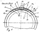
- FIG. 1 shows an embodiment of a plastic container known from DE 197 37 900 C2 and EP 0 899 205 B 1 as a round container 1, the upper edge of which has a protective element 2 extending over the greater part of the container circumference, which is formed integrally with the container wall 3 is.
- the protective element 2 covers the peripheral edge of a closure element to be applied to the container 1 and hinders the decrease of the latter.
- the protective element 2 has a stepped recess 4, which extends partially over the circumferential length of the upper edge of the container 1 and thus partially over the circumferential length of the closure element.
- a tear-off tab 5 is fitted in the form of a perforation-like tamper-evident closure, wherein a projecting from the lower edge of the tear-off 5 projection 6 is connected via predetermined breaking points 7 with the container wall 3, the upper and lower edge of the tear-off 5 with the aligned upper and lower edge of the protective element 2 and parts 8 of the tear-off tab 5 are on both sides of its projection 8 with its inner surface 9 via predetermined breaking points 10 holding manner connected with stepped heels 11 of the protective element 3.
- the circumferential outer surface 13 of the tear tab 5 is formed by a plurality of crenellated elevations 12, which are arranged in the circumferential direction at the same distance from each other.
- the tear-off tab 5 As illustrated in FIG. 2, which schematically shows a circumferential portion of the tear-off tab 5 of the known device according to FIG. 1 in the area indicated by the circle X, the tear-off tab 5, the inner surface of which is flat, has wall thicknesses of different thickness over its length experienced in the injection-moderate production of the device different material contractions.
- sink marks or contraction sinks 15 can thus occur which are particularly disadvantageous in labeling the marking surface of the tear-off tab 5, e.g. the risk of wrinkling of a label applied to the label surface is given.
- Fig. 3 now shows in plan view a portion of a tear-off tab 5 in the corresponding region X of an embodiment of the device according to the invention, which has in general the elements with the device of FIG. 1 in common.
- Fig. 3 according to the invention in the circumferential direction of the tear-off 5 their entire inner surface 9 and their entire outer surface 13b equidistant from each other and run in the plan view of the tear-5 - run in oscillation lines, which are mirror images of each other, have identical vibrations and are circumferentially offset by a vibration to each other.
- the periodic vibration levels or vibrating groups are truncated pyramidal and form in the course of the oscillation line of the entire outer surface of the tear-off 5, the crenellated elevations 12 of the tear-off 5, in the direction of the common normal to the container wall 3 on the circumferential outer surface 14 of Protective element 2 of the device project.
- the tear-off tab 5 is held on the container wall 3 by way of the projection 6 via the predetermined breaking points 7.
- the projection 6 is arranged in the middle of the height of the inner surface 9 of the tear-off tab 5 and is stabilized by attached to its lower surface, not shown supporting webs.
- the tab ends 16 of the tear-off tab 5 are loose.
- the course of the oscillation lines of the inner surface 9 and the outer surface 12b of the tear-off tab 5 can also be a rectangular-curve-like or have the shape of an approximated sinusoid, as shown schematically in FIG. 4 or FIG. 5. Also in these embodiments, the advantages of the invention shown in connection with FIG. 3 are correspondingly given.
Landscapes
- Engineering & Computer Science (AREA)
- Mechanical Engineering (AREA)
- Closures For Containers (AREA)
- Closing Of Containers (AREA)
Abstract
Description
- Die Erfindung betrifft eine Vorrichtung zur Sicherung von durch ein Verschlußelement verschlossenen Kunststoffbehältern gegen unbefugte Erstöffnung, deren oberer Rand ein umlaufendes, mit der Behälterwand einstückig ausgebildetes und den umlaufenden Rand des Verschlußelementes abeckendes Schutzelement umfaßt, durch das die Abnahme des Verschlußelementes behindert ist und das mindestens eine Ausnehmung aufweist, die sich teilweise über die Umfangslänge des Verschlußelementes erstreckt und in die eine Abreißlasche eingepaßt ist, deren obere Kante und untere Kante mit der oberen Kante bzw. der unteren Kante des Schutzelementes jeweils in einer Ebene liegen (fluchten) und die an der umfangsmäßigen Innenoberfläche eine über Sollbruchstellen mit der Behälterwand verbundene Auskragung aufweist und deren Außenumfang von außenliegenden Flächenabschnitten einer Vielzahl umfangsmäßig im gleichen Abstand zueinander angeordneter, jeweils in einer gleichen Höhe über die umfangsmäßige Außenfläche des Schutzelementes in Richtung der gemeinsamen Normalen auf die Behälterwand vorragender zinnenartiger Erhebungen der Abreißlasche gebildet ist, wobei die den Außenumfang der Abreißlasche bildenden jeweiligen äußeren Flächenabschnitte der Erhebungen eine sich in Umfangsrichtung erstreckende Kennzeichnungsfläche bilden und die Abreißlasche nach ihrem Entfernen den Rand des Verschlußelementes dem Öffnungsgriff zugänglich macht.
- Bei einer bekannten, auf die Anmelderin zurückgehenden Vorrichtung der eingangs erwähnten Art (DE 197 37 900 C2 und EP 0 899 205 B1) weist die Abreißlasche, deren umfangsmäßige Außenfläche von einer Vielzahl umfangsmäßig im gleichen Abstand zueinander angeordneter, jeweils in einer gleichen gerinfügigen Höhe über die umfangsmäßige Außenfläche des Schutzelementes in Richtung zur gemeinsamen Normalen auf die Behälterwand vorragender, zinnenartiger Erhebungen gebildet ist, unterschiedlich dicke Wandstärken über ihre umfangsmäßige Länge auf und die Abreißlasche ist beidseitig ihrer Auskragung im Bereich der stufenförmigen Ausnehmung mit der Lascheninnenfläche über Sollbruchstellen auch mit dem Schutzelement halterungsmäßig verbunden. Da ungleichmäßige Wandungsdicken bei der Fertigung unterschiedliche Kontraktionswirkungen erfahren und somit unterschiedlich materialmäßig schwinden, können bei der bekannten Vorrichtung die äußeren Flächenabschnitte der Erhebungen, die die sich in Umfangsrichtung des Abreißlasche erstreckende Kennzeichnungsfläche (Druck- und/oder Etikettierfläche) bilden, unerwünschte Materialeinfälle oder Senkungen aufweisen, was z.B. ein fehlerfreies Etikettieren nicht möglich macht, d.h. ein nicht glatt aufgezogenes Etikett zur Folge haben kann. Entsprechende Beinträchtigungen können auch bei der Bedruckung der umfangsmäßigen Außenfläche der Abreißlasche auftreten.
- Der Erfindung liegt die Aufgabe zugrunde, eine Vorrichtung der eingangs erwähnten Art zur Verfügung zu stellen, bei der die genannten Nachteile praktisch ausgeschlossen werden können und die zugleich material- und energiesparender mit erhöhter Stabilität und fertigungsoptimierend herstellbar ist.
- Diese Aufgabe wird erfindungsgemäß dadurch gelöst, daß in Umfangsrichtung der Abreißlasche deren Innenoberfläche und deren Außenoberfläche stets gleichbeabstandet zueinander und - gesehen in Draufsicht auf die Abreißlasche in ihrer gehalterten Position - in Schwingungslinien verlaufen, die zueinander spiegelbildlich sind, identische Schwingungen aufweisen und in Umfangsrichtung um eine Schwingung zueinander versetzt sind, wobei die außenliegenden, die Kennzeichnungsfläche der Abreißlasche bildenden Flächenabschnitte der Erhebungen der Abreißlasche jeweils praktisch frei von einem Oberflächeneinfall (einer Kontraktionsenke) sind.
- Vorzugsweise kann der Verlauf der Schwingungslinien der Innenoberfläche und der Außenoberfläche der Abreißlasche periodisch pyramidenstumpfartige Schwingungskuppen aufweisen oder rechteckkurvenartig oder in Form einer angenäherten Sinuskurve verhältnismäßig hoher Schwingungsfrequenz ausgebildet sein.
- Durch die Vermeidung unterschiedlicher Wandstärken der Abreißlasche der erfindungsgemäßen Vorrichtung wird ein Materialschwund an dem Kennzeichnungsflächenabschnitt jeder Erhebung der Abreißlasche vermieden. Außerdem ergibt sich in fertigungsoptimierender Weise eine erhebliche Material- und Energieersparnis bei der Herstellung der Vorrichtung im Spritzgußverfahren. Durch die Verminderung der Kontraktionswirkung im Kennzeichnungsflächenbereich jeder Erhebung der Abreißlasche wird deren Stabilität verbessert, und es ergeben sich zudem die Fertigung optimierende Zugriffszeiten.
- Die Erfindung wird nun in Gegenüberstellung zum Stand der Technik nach der DE 197 37 900 C2 und EP 0 899 205 B1 anhand der Zeichnungen erläutert. In diesen sind:
- Fig. 1 eine bruchstückartige Draufsicht einer Ausführungsform einer Vorrichtung nach dem Stand der Technik gemäß der DE 197 37 900 C2 und EP 0 899 205 B1, bei der der Außenumfang der Abreißlasche, der von den außenliegenden Flächenabschnitten der Erhebungen der Abreißlasche gebildet ist, - gesehen in radialer Richtung - von der umfangsmäßigen Außenfläche des einstückig mit der Behälterwand ausgebildeten Schutzelementes vorsteht,
- Fig. 2 eine Draufsicht auf ein schematisch dargestelltes umfangsmäßiges Teilstück der Abreißlasche der bekannten Vorrichtung gemäß Fig. 1, wobei die Auskragung der Abreißlasche nicht dargestellt ist, und
- Fig. 3, 4 und 5 jeweils eine Draufsicht auf ein schematisch dargestelltes Teilstück der Abreißlasche von drei bevorzugten Ausführungsformen der erfindungsgemäß Vorrichtung.
- Fig. 1 zeigt eine Ausführungsform eines nach der DE 197 37 900 C2 und der EP 0 899 205 B 1 bekannten Kunststoffbehälters als Rundbehälter 1, dessen oberer Rand ein über den größten Teil des Behälterumfangs umlaufendes Schutzelement 2 aufweist, das einstückig mit der Behälterwand 3 ausgebildet ist. Das Schutzelement 2 deckt den umlaufenden Rand eines auf den Behälter 1 aufzubringenden Verschlußelementes ab und behindert die Abnahme des letzteren. Wie Fig. 1 verdeutlicht, weist das Schutzelement 2 eine stufenförmige Ausnehmung 4 auf, die sich teilweise über die Umfangslänge des oberen Rands des Behälters 1 und damit teilweise über die Umfangslänge des Verschlußelementes erstreckt. In die stufenförmige Ausnehmung 4 ist eine Abreißlasche 5 in Form eines perforationsartigen Originalitätsverschlusses eingepaßt, wobei eine sich von der unteren Kante der Abreißlasche 5 erstreckende Auskragung 6 über Sollbruchstellen 7 mit der Behälterwand 3 verbunden ist, die obere und die untere Kante der Abreißlasche 5 mit der oberen bzw. unteren Kante des Schutzelementes 2 fluchten und Teile 8 der Abreißlasche 5 beidseitig ihrer Auskragung 8 mit ihrer Innenoberfläche 9 über Sollbruchstellen 10 halterungsmäßig mit stufenförmigen Absätzen 11 des Schutzelementes 3 verbunden sind.
- Die umfangsmäßige Außenfläche 13 der Abreißlasche 5 ist von einer Vielzahl zinnenartiger Erhebungen 12 gebildet, die in Umfangsrichtung im gleichen Abstand zueinander angeordnet sind. Die zinnenartigen Erhebungen 12, deren Grundriß pyramidenförmig ist, ragen jeweils in einer gleichen geringfügigen Höhe über die umfangsmäßige Außenfläche 14 des Schutzelementes 2 in radialer Richtung - gesehen in Fig. 1 - vor derart, daß ihre jeweiligen umfangsmäßigen äußeren Flächenabschnitte 13a auf einer Umfangslinie liegen und den Außenumfang 13 der Abreißlasche 5 und damit allein eine maschinell bedruckbare Kennzeichnungsfläche bilden.
- Wie Fig. 2 verdeutlicht, die schematisch ein umfangsmäßiges Teilstück der Abreißlasche 5 der bekannten Vorrichtung nach Fig. 1 in dem durch den Kreis X gekennzeichneten Bereich zeigt, weist die Abreißlasche 5, deren Innenoberfläche plan ist, über ihre Länge unterschiedlich dicke Wandstärken auf, die bei der spritzgußmäßigen Fertigung der Vorrichtung unterschiedliche Materialkontraktionen erfahren. Auf der umfangsmäßigen äußeren Flächenabschnitt 13a jeder zinnenartigen Erhebung 13 der Abreißlasche 5 können somit Einfallstellen oder Kontraktionssenken 15 auftreten, die sich besonders bei einer Etikettierung der Kennzeichnungsfläche der Abreißlasche 5 nachteilig auswirken, da z.B. die Gefahr von Faltenbildung eines auf die Kennzeichnungsfläche aufgebrachten Etiketts gegeben ist.
- Fig. 3 zeigt nun in der Draufsicht ein Teilstück einer Abreißlasche 5 im entsprechenden Bereich X einer Ausführungsform der erfindungsgemäßen Vorrichtung, die im allgemeinen Aufbau die Elemente mit der Vorrichtung nach Fig. 1 gemein hat. Wie aus Fig. 3 hervorgeht, sind erfindungsgemäß in Umfangsrichtung der Abreißlasche 5 deren gesamte Innenoberfläche 9 und deren gesamte Außenoberfläche 13b gleichbeabstandet zueinander und verlaufen- gesehen in der Draufsicht auf die Abreißlasche 5 - in Schwingungslinien verlaufen, die zueinander spiegelbildlich sind, identische Schwingungen aufweisen und in Umfangsrichtung um eine Schwingung zueinander versetzt sind. Bei der Ausführungsform gemäß Fig. 3 sind die periodischen Schwingungshöhen oder Schwingungskuppen pyramidenstumpfartig und bilden im Verlauf der Schwingungslinie der gesamten Außenfläche der Abreißlasche 5 die zinnenartrigen Erhebungen 12 der Abreißlasche 5, die in Richtung der gemeinsamen Normalen auf die Behälterwand 3 über die umfangsmäßige Außenfläche 14 des Schutzelementes 2 der Vorrichtung vorragen. Wie Fig. 3 weiter schematisch zeigt, ist die Abreißlasche 5 mittels der Auskrakung 6 über die Sollbruchstellen 7 an der Behälterwand 3 gehaltert. Die Auskragung 6 ist in Höhenmitte der Innenoberfläche 9 der Abreißlasche 5 angeordnet und wird von an ihrer Unterfläche angesetzten, nicht dargestellten Stützstegen stabilisiert. Die Laschenenden 16 der Abreißlasche 5 sind lose.
- Infolge der gleichmäßigen Wandstärke d der Abreißlasche 5 und ihrer speziellen Schwingungsführung über ihre gesamte umfangsmäßige Länge ergibt sich bei der Fertigung der Ausführungsform der Vorrichtung gemäß Fig. 3 eine Materialkontraktion derart, daß auf dem außenliegenden Flächenabschnitt 13a jeder zinnenartigen Erhebungen 12 der Abreißlasche 5 keine Einfallstelle oder Kontraktionssenke auftritt, so daß eine glatte Kennzeichnungsfläche der Abreißlasche 5 für ein fehlerfreies Etikettieren und/oder Bedrucken gewährleistet ist.
- Der Verlauf der Schwingungslinien der Innenoberfläche 9 und der Außenoberfläche 12b der Abreißlasche 5 kann auch rechteckkurvenartig sein oder die Form einer angenäherten Sinuskurve aufweisen, wie schematisch in Fig. 4 bzw. Fig. 5 dargestellt ist. Auch bei diesen Ausführungsformen sind entsprechend die im Zusammenhang mit Fig. 3 aufgezeigten Vorteile der Erfindung gegeben.
-
- 1
- Behälter
- 2
- Schutzelement
- 3
- Behälterwand
- 4
- Ausnehmung des Schutzelementes
- 5
- Abreißlasche
- 6
- Auskragung der Abreißlasche
- 7
- Sollbruchstellen an der Auskragung
- 8
- Teile der Abreißlasche beidseitig der Auskragung
- 9
- Innenoberfläche der Abreißlasche
- 10
- Sollbruchstellen
- 11
- stufenförmige Absätze des Schutzelementes
- 12
- Erhebungen der Abreißlasche
- 13
- Außenumfang der Abreißlasche
- 13a
- außenliegende Flächenabschnitte der Erhebungen
- 13b
- Außenfläche der Abreißlasche
- 14
- Außenfläche des Schutzelementes
- 15
- Einfallstelle, Kontraktionssenke
- 16
- Ende der Abreißlasche
Claims (4)
- Vorrichtung zur Sicherung von durch ein Verschlußelement verschlossenen Kunststoffbehältern (1) gegen unbefugte Erstöffnung, deren oberer Rand ein umlaufendes, mit der Behälterwand (3) einstückig ausgebildetes und den umlaufenden Rand des Verschlußelementes abeckendes Schutzelement (2) umfaßt, durch das die Abnahme des Verschlußelementes behindert ist und das mindestens eine Ausnehmung (4) aufweist, die sich teilweise über die Umfangslänge des Verschlußelementes erstreckt und in die eine Abreißlasche (5) eingepaßt ist, deren obere Kante und untere Kante mit der oberen Kante bzw. der unteren Kante des Schutzelementes (2) jeweils in einer Ebene liegen (fluchten) und die an der umfangsmäßigen Innenfläche (9) eine über Sollbruchstellen (7) mit der Behälterwand (3) verbundene Auskragung (6) aufweist und deren Außenumfang von außenliegenden Flächenabschnitten (13a) einer Vielzahl umfangsmäßig im gleichen Abstand zueinander angeordneter, jeweils in einer gleichen Höhe über die umfangsmäßige Außenfläche (14) des Schutzelementes (2) in Richtung der gemeinsamen Normalen auf die Behälterwand (3) vorragender, zinnenartiger Erhebungen (12) der Abreißlasche (5) gebildet ist, wobei die den Außenumfang (13) der Abreißlasche (5) bildenden jeweiligen äußeren Flächenabschnitte (13a) der Erhebungen (12) eine sich in Umfangsrichtung erstreckende Kennzeichnungsfläche bilden und die Abreißlasche (5) nach ihrem Entfernen den Rand des Verschlußelementes dem Öffhungsgriff zugänglich macht,
dadurch gekennzeichnet,
daß in Umfangsrichtung der Abreißlasche (5) deren Innenoberfläche (9) und deren Außenoberfläche (13b) stets gleichbeabstandet zueinander und - gesehen in der Draufsicht auf die Abreißlasche (5) in ihrer gehalterter Position - in Schwingungslinien verlaufen, die zueinander spiegelbildlich sind, identische Schwingungen aufweisen und in Umfangsrichtung um eine Schwingung zueinander versetzt sind, wobei die außenliegenden, die Kennzeichnungsfläche der Abreißlasche (5) bildenden Flächenabschnitten (13a) der Erhebungen (12) der Abreißlasche (5) jeweils praktisch frei von einem Oberflächeneinfall (einer Kontraktionssenke) sind. - Vorrichtung nach Anspruch 1, dadurch gekennzeichnet, daß der Verlauf der Schwingungslinien der Innenoberfläche (9) und der Außenoberfläche (13b) der Abreißlasche (5) periodisch pyramidenstumpfartige Schwingungskuppen aufweist.
- Vorrichtung nach Anspruch 1, dadurch gekennzeichnet, daß der Verlauf der Schwingungslinien der Innenoberfläche (9) und der Außenoberfläche (13b) der Abreißlasche (5) rechteckkurvenartig ist
- Vorrichtung nach Anspruch 1, dadurch gekennzeichnet, daß der Verlauf der Schwingungslinien der Innenoberfläche (9) und der Außenoberfläche (13b) der Abreißlasche (5) die Form einer angenäherten Sinuskurve aufweist.
Priority Applications (5)
| Application Number | Priority Date | Filing Date | Title |
|---|---|---|---|
| AT05090010T ATE425924T1 (de) | 2005-01-25 | 2005-01-25 | Vorrichtung zur sicherung von durch ein verschlusselement verschlossenen kunststoffbehaltern |
| DK05090010T DK1683733T3 (da) | 2005-01-25 | 2005-01-25 | Apparat til sikring af plastbeholdere, som er lukket ved hjælp af et lukkeelement |
| PL05090010T PL1683733T3 (pl) | 2005-01-25 | 2005-01-25 | Urządzenie do zabezpieczania zbiorników z tworzywa sztucznego zamkniętych elementem zamykającym |
| EP05090010A EP1683733B1 (de) | 2005-01-25 | 2005-01-25 | Vorrichtung zur Sicherung von durch ein Verschlusselement verschlossenen Kunststoffbehältern |
| DE502005006873T DE502005006873D1 (de) | 2005-01-25 | 2005-01-25 | Vorrichtung zur Sicherung von durch ein Verschlusselement verschlossenen Kunststoffbehältern |
Applications Claiming Priority (1)
| Application Number | Priority Date | Filing Date | Title |
|---|---|---|---|
| EP05090010A EP1683733B1 (de) | 2005-01-25 | 2005-01-25 | Vorrichtung zur Sicherung von durch ein Verschlusselement verschlossenen Kunststoffbehältern |
Publications (2)
| Publication Number | Publication Date |
|---|---|
| EP1683733A1 true EP1683733A1 (de) | 2006-07-26 |
| EP1683733B1 EP1683733B1 (de) | 2009-03-18 |
Family
ID=34938397
Family Applications (1)
| Application Number | Title | Priority Date | Filing Date |
|---|---|---|---|
| EP05090010A Expired - Lifetime EP1683733B1 (de) | 2005-01-25 | 2005-01-25 | Vorrichtung zur Sicherung von durch ein Verschlusselement verschlossenen Kunststoffbehältern |
Country Status (5)
| Country | Link |
|---|---|
| EP (1) | EP1683733B1 (de) |
| AT (1) | ATE425924T1 (de) |
| DE (1) | DE502005006873D1 (de) |
| DK (1) | DK1683733T3 (de) |
| PL (1) | PL1683733T3 (de) |
Citations (2)
| Publication number | Priority date | Publication date | Assignee | Title |
|---|---|---|---|---|
| DE29505551U1 (de) * | 1994-05-31 | 1995-07-06 | Spritzgußwerk KG Richard Rassbach GmbH & Co, 13509 Berlin | Vorrichtung zur Sicherung von durch ein Verschlußelement verschlossenen Behältern jeder Art gegen unbefugte Erstöffnung |
| DE29715566U1 (de) * | 1997-08-31 | 1998-02-05 | Spritzgußwerk KG Richard Rassbach GmbH & Co, 13509 Berlin | Vorrichtung zur Sicherung von durch ein Verschlußelement verschlossenen Kunststoffbehältern |
-
2005
- 2005-01-25 DK DK05090010T patent/DK1683733T3/da active
- 2005-01-25 DE DE502005006873T patent/DE502005006873D1/de not_active Expired - Lifetime
- 2005-01-25 AT AT05090010T patent/ATE425924T1/de not_active IP Right Cessation
- 2005-01-25 PL PL05090010T patent/PL1683733T3/pl unknown
- 2005-01-25 EP EP05090010A patent/EP1683733B1/de not_active Expired - Lifetime
Patent Citations (2)
| Publication number | Priority date | Publication date | Assignee | Title |
|---|---|---|---|---|
| DE29505551U1 (de) * | 1994-05-31 | 1995-07-06 | Spritzgußwerk KG Richard Rassbach GmbH & Co, 13509 Berlin | Vorrichtung zur Sicherung von durch ein Verschlußelement verschlossenen Behältern jeder Art gegen unbefugte Erstöffnung |
| DE29715566U1 (de) * | 1997-08-31 | 1998-02-05 | Spritzgußwerk KG Richard Rassbach GmbH & Co, 13509 Berlin | Vorrichtung zur Sicherung von durch ein Verschlußelement verschlossenen Kunststoffbehältern |
Also Published As
| Publication number | Publication date |
|---|---|
| EP1683733B1 (de) | 2009-03-18 |
| ATE425924T1 (de) | 2009-04-15 |
| PL1683733T3 (pl) | 2009-08-31 |
| DE502005006873D1 (de) | 2009-04-30 |
| DK1683733T3 (da) | 2009-07-20 |
Similar Documents
| Publication | Publication Date | Title |
|---|---|---|
| DE69630596T2 (de) | Originalitätsverschluss mit garantieband | |
| EP0593396B1 (de) | Garantieverschluss aus Kunststoff | |
| DE60214501T2 (de) | Garantieverschluss und Behälter mit Vorkehrungen zum Ableiten von Flüssigkeiten und Verfahren zu deren Herstellung | |
| DE69334022T2 (de) | Form zum Formen von Sicherheitsverschlusskappen | |
| EP0424897B1 (de) | Kunststoffdeckel für blasgeformte Kunststoffässer | |
| DE3319709A1 (de) | Eingriffe anzeigender verschluss | |
| EP2382139B1 (de) | Schraubverschluss mit sicherheitsring und sicherheitssiegel, sowie verfahren zur bereitstellung eines behälters mit diesem schraubverschluss | |
| DE3416179C2 (de) | ||
| DE3714582A1 (de) | Verpackung mit garantieverschluss | |
| DE69503825T2 (de) | Kunststoffkappe | |
| EP1397296B1 (de) | Schraubkappe mit garantieband | |
| EP0243531A2 (de) | Sicherungsring für Flaschen-, Weithals- o.ä. Behälterverschlüsse | |
| EP0459017B1 (de) | Verfahren zur Herstellung eines Verschlussdeckels aus Pappe | |
| EP1683733B1 (de) | Vorrichtung zur Sicherung von durch ein Verschlusselement verschlossenen Kunststoffbehältern | |
| EP2437982B1 (de) | Originalitätssicherung bei einem kunststoffbehälter zur aufnahme von lebensmitteln | |
| EP3981703A1 (de) | Behälter mit aufprellbarem deckel | |
| EP0899205B1 (de) | Vorrichtung zur Sicherung von durch ein Verschlusselement verschlossenen Kunststoffbehältern und Verfahren zur Kennzeichnung der Vorrichtung | |
| EP0564999B1 (de) | Flaschenkappe mit Sicherungsring | |
| EP0129612B1 (de) | Garantiering für eine Schraubkappe | |
| CH484789A (de) | Sicherheits-Drehverschluss für Behälter | |
| DE102017001839B3 (de) | Lösbarer Verschluss und Flasche mit einem Kronenmundstück | |
| DE3508478A1 (de) | Behaelterverschluss mit plombierung | |
| EP2295333B1 (de) | Kunststoff-Rahmen mit integriertem Bügel für eine Dose | |
| DE29715566U1 (de) | Vorrichtung zur Sicherung von durch ein Verschlußelement verschlossenen Kunststoffbehältern | |
| EP0476259A1 (de) | Verschlusskappe für mit einem Partialgewinde versehenen Behälter |
Legal Events
| Date | Code | Title | Description |
|---|---|---|---|
| PUAI | Public reference made under article 153(3) epc to a published international application that has entered the european phase |
Free format text: ORIGINAL CODE: 0009012 |
|
| AK | Designated contracting states |
Kind code of ref document: A1 Designated state(s): AT BE BG CH CY CZ DE DK EE ES FI FR GB GR HU IE IS IT LI LT LU MC NL PL PT RO SE SI SK TR |
|
| AX | Request for extension of the european patent |
Extension state: AL BA HR LV MK YU |
|
| 17P | Request for examination filed |
Effective date: 20070124 |
|
| AKX | Designation fees paid |
Designated state(s): AT BE BG CH CY CZ DE DK EE ES FI FR GB GR HU IE IS IT LI LT LU MC NL PL PT RO SE SI SK TR |
|
| 17Q | First examination report despatched |
Effective date: 20080229 |
|
| GRAP | Despatch of communication of intention to grant a patent |
Free format text: ORIGINAL CODE: EPIDOSNIGR1 |
|
| GRAS | Grant fee paid |
Free format text: ORIGINAL CODE: EPIDOSNIGR3 |
|
| GRAA | (expected) grant |
Free format text: ORIGINAL CODE: 0009210 |
|
| AK | Designated contracting states |
Kind code of ref document: B1 Designated state(s): AT BE BG CH CY CZ DE DK EE ES FI FR GB GR HU IE IS IT LI LT LU MC NL PL PT RO SE SI SK TR |
|
| REG | Reference to a national code |
Ref country code: GB Ref legal event code: FG4D Free format text: NOT ENGLISH |
|
| REG | Reference to a national code |
Ref country code: CH Ref legal event code: EP |
|
| REG | Reference to a national code |
Ref country code: IE Ref legal event code: FG4D Free format text: LANGUAGE OF EP DOCUMENT: GERMAN |
|
| REF | Corresponds to: |
Ref document number: 502005006873 Country of ref document: DE Date of ref document: 20090430 Kind code of ref document: P |
|
| REG | Reference to a national code |
Ref country code: DK Ref legal event code: T3 |
|
| PG25 | Lapsed in a contracting state [announced via postgrant information from national office to epo] |
Ref country code: LT Free format text: LAPSE BECAUSE OF FAILURE TO SUBMIT A TRANSLATION OF THE DESCRIPTION OR TO PAY THE FEE WITHIN THE PRESCRIBED TIME-LIMIT Effective date: 20090318 Ref country code: SI Free format text: LAPSE BECAUSE OF FAILURE TO SUBMIT A TRANSLATION OF THE DESCRIPTION OR TO PAY THE FEE WITHIN THE PRESCRIBED TIME-LIMIT Effective date: 20090318 Ref country code: FI Free format text: LAPSE BECAUSE OF FAILURE TO SUBMIT A TRANSLATION OF THE DESCRIPTION OR TO PAY THE FEE WITHIN THE PRESCRIBED TIME-LIMIT Effective date: 20090318 |
|
| PG25 | Lapsed in a contracting state [announced via postgrant information from national office to epo] |
Ref country code: SE Free format text: LAPSE BECAUSE OF FAILURE TO SUBMIT A TRANSLATION OF THE DESCRIPTION OR TO PAY THE FEE WITHIN THE PRESCRIBED TIME-LIMIT Effective date: 20090618 |
|
| REG | Reference to a national code |
Ref country code: PL Ref legal event code: T3 |
|
| REG | Reference to a national code |
Ref country code: IE Ref legal event code: FD4D |
|
| PG25 | Lapsed in a contracting state [announced via postgrant information from national office to epo] |
Ref country code: CZ Free format text: LAPSE BECAUSE OF FAILURE TO SUBMIT A TRANSLATION OF THE DESCRIPTION OR TO PAY THE FEE WITHIN THE PRESCRIBED TIME-LIMIT Effective date: 20090318 Ref country code: PT Free format text: LAPSE BECAUSE OF FAILURE TO SUBMIT A TRANSLATION OF THE DESCRIPTION OR TO PAY THE FEE WITHIN THE PRESCRIBED TIME-LIMIT Effective date: 20090826 Ref country code: IE Free format text: LAPSE BECAUSE OF FAILURE TO SUBMIT A TRANSLATION OF THE DESCRIPTION OR TO PAY THE FEE WITHIN THE PRESCRIBED TIME-LIMIT Effective date: 20090318 Ref country code: EE Free format text: LAPSE BECAUSE OF FAILURE TO SUBMIT A TRANSLATION OF THE DESCRIPTION OR TO PAY THE FEE WITHIN THE PRESCRIBED TIME-LIMIT Effective date: 20090318 Ref country code: ES Free format text: LAPSE BECAUSE OF FAILURE TO SUBMIT A TRANSLATION OF THE DESCRIPTION OR TO PAY THE FEE WITHIN THE PRESCRIBED TIME-LIMIT Effective date: 20090629 |
|
| PG25 | Lapsed in a contracting state [announced via postgrant information from national office to epo] |
Ref country code: SK Free format text: LAPSE BECAUSE OF FAILURE TO SUBMIT A TRANSLATION OF THE DESCRIPTION OR TO PAY THE FEE WITHIN THE PRESCRIBED TIME-LIMIT Effective date: 20090318 Ref country code: IS Free format text: LAPSE BECAUSE OF FAILURE TO SUBMIT A TRANSLATION OF THE DESCRIPTION OR TO PAY THE FEE WITHIN THE PRESCRIBED TIME-LIMIT Effective date: 20090718 Ref country code: RO Free format text: LAPSE BECAUSE OF FAILURE TO SUBMIT A TRANSLATION OF THE DESCRIPTION OR TO PAY THE FEE WITHIN THE PRESCRIBED TIME-LIMIT Effective date: 20090318 |
|
| PLBE | No opposition filed within time limit |
Free format text: ORIGINAL CODE: 0009261 |
|
| STAA | Information on the status of an ep patent application or granted ep patent |
Free format text: STATUS: NO OPPOSITION FILED WITHIN TIME LIMIT |
|
| PG25 | Lapsed in a contracting state [announced via postgrant information from national office to epo] |
Ref country code: BG Free format text: LAPSE BECAUSE OF FAILURE TO SUBMIT A TRANSLATION OF THE DESCRIPTION OR TO PAY THE FEE WITHIN THE PRESCRIBED TIME-LIMIT Effective date: 20090618 |
|
| 26N | No opposition filed |
Effective date: 20091221 |
|
| PG25 | Lapsed in a contracting state [announced via postgrant information from national office to epo] |
Ref country code: MC Free format text: LAPSE BECAUSE OF NON-PAYMENT OF DUE FEES Effective date: 20100131 |
|
| REG | Reference to a national code |
Ref country code: CH Ref legal event code: PL |
|
| PG25 | Lapsed in a contracting state [announced via postgrant information from national office to epo] |
Ref country code: LI Free format text: LAPSE BECAUSE OF NON-PAYMENT OF DUE FEES Effective date: 20100131 Ref country code: CH Free format text: LAPSE BECAUSE OF NON-PAYMENT OF DUE FEES Effective date: 20100131 Ref country code: GR Free format text: LAPSE BECAUSE OF FAILURE TO SUBMIT A TRANSLATION OF THE DESCRIPTION OR TO PAY THE FEE WITHIN THE PRESCRIBED TIME-LIMIT Effective date: 20090619 |
|
| PG25 | Lapsed in a contracting state [announced via postgrant information from national office to epo] |
Ref country code: IT Free format text: LAPSE BECAUSE OF FAILURE TO SUBMIT A TRANSLATION OF THE DESCRIPTION OR TO PAY THE FEE WITHIN THE PRESCRIBED TIME-LIMIT Effective date: 20090318 |
|
| PGFP | Annual fee paid to national office [announced via postgrant information from national office to epo] |
Ref country code: DK Payment date: 20110125 Year of fee payment: 7 |
|
| PG25 | Lapsed in a contracting state [announced via postgrant information from national office to epo] |
Ref country code: AT Free format text: LAPSE BECAUSE OF NON-PAYMENT OF DUE FEES Effective date: 20100125 |
|
| PGFP | Annual fee paid to national office [announced via postgrant information from national office to epo] |
Ref country code: NL Payment date: 20110125 Year of fee payment: 7 Ref country code: FR Payment date: 20110201 Year of fee payment: 7 Ref country code: PL Payment date: 20110117 Year of fee payment: 7 |
|
| PGFP | Annual fee paid to national office [announced via postgrant information from national office to epo] |
Ref country code: BE Payment date: 20110124 Year of fee payment: 7 |
|
| PGFP | Annual fee paid to national office [announced via postgrant information from national office to epo] |
Ref country code: GB Payment date: 20110121 Year of fee payment: 7 Ref country code: DE Payment date: 20110326 Year of fee payment: 7 |
|
| BERE | Be: lapsed |
Owner name: SPRITZGUSSWERK KG RICHARD RASSBACH G.M.B.H. & CO. Effective date: 20120131 |
|
| REG | Reference to a national code |
Ref country code: NL Ref legal event code: V1 Effective date: 20120801 |
|
| PG25 | Lapsed in a contracting state [announced via postgrant information from national office to epo] |
Ref country code: CY Free format text: LAPSE BECAUSE OF FAILURE TO SUBMIT A TRANSLATION OF THE DESCRIPTION OR TO PAY THE FEE WITHIN THE PRESCRIBED TIME-LIMIT Effective date: 20090318 |
|
| REG | Reference to a national code |
Ref country code: DK Ref legal event code: EBP |
|
| GBPC | Gb: european patent ceased through non-payment of renewal fee |
Effective date: 20120125 |
|
| PG25 | Lapsed in a contracting state [announced via postgrant information from national office to epo] |
Ref country code: LU Free format text: LAPSE BECAUSE OF NON-PAYMENT OF DUE FEES Effective date: 20100125 Ref country code: HU Free format text: LAPSE BECAUSE OF FAILURE TO SUBMIT A TRANSLATION OF THE DESCRIPTION OR TO PAY THE FEE WITHIN THE PRESCRIBED TIME-LIMIT Effective date: 20090919 |
|
| REG | Reference to a national code |
Ref country code: FR Ref legal event code: ST Effective date: 20120928 |
|
| PG25 | Lapsed in a contracting state [announced via postgrant information from national office to epo] |
Ref country code: TR Free format text: LAPSE BECAUSE OF FAILURE TO SUBMIT A TRANSLATION OF THE DESCRIPTION OR TO PAY THE FEE WITHIN THE PRESCRIBED TIME-LIMIT Effective date: 20090318 Ref country code: GB Free format text: LAPSE BECAUSE OF NON-PAYMENT OF DUE FEES Effective date: 20120125 Ref country code: DE Free format text: LAPSE BECAUSE OF NON-PAYMENT OF DUE FEES Effective date: 20120801 |
|
| REG | Reference to a national code |
Ref country code: DE Ref legal event code: R119 Ref document number: 502005006873 Country of ref document: DE Effective date: 20120801 |
|
| PG25 | Lapsed in a contracting state [announced via postgrant information from national office to epo] |
Ref country code: FR Free format text: LAPSE BECAUSE OF NON-PAYMENT OF DUE FEES Effective date: 20120131 Ref country code: BE Free format text: LAPSE BECAUSE OF NON-PAYMENT OF DUE FEES Effective date: 20120131 |
|
| PG25 | Lapsed in a contracting state [announced via postgrant information from national office to epo] |
Ref country code: NL Free format text: LAPSE BECAUSE OF NON-PAYMENT OF DUE FEES Effective date: 20120801 Ref country code: DK Free format text: LAPSE BECAUSE OF NON-PAYMENT OF DUE FEES Effective date: 20120131 |
|
| REG | Reference to a national code |
Ref country code: PL Ref legal event code: LAPE |
|
| PG25 | Lapsed in a contracting state [announced via postgrant information from national office to epo] |
Ref country code: PL Free format text: LAPSE BECAUSE OF NON-PAYMENT OF DUE FEES Effective date: 20120125 |