EP1683665B1 - Dispositif de capteur - Google Patents
Dispositif de capteur Download PDFInfo
- Publication number
- EP1683665B1 EP1683665B1 EP06000975A EP06000975A EP1683665B1 EP 1683665 B1 EP1683665 B1 EP 1683665B1 EP 06000975 A EP06000975 A EP 06000975A EP 06000975 A EP06000975 A EP 06000975A EP 1683665 B1 EP1683665 B1 EP 1683665B1
- Authority
- EP
- European Patent Office
- Prior art keywords
- arrangement according
- sensor arrangement
- sensor
- sensor element
- supporting plate
- Prior art date
- Legal status (The legal status is an assumption and is not a legal conclusion. Google has not performed a legal analysis and makes no representation as to the accuracy of the status listed.)
- Not-in-force
Links
- 230000008878 coupling Effects 0.000 claims abstract description 19
- 238000010168 coupling process Methods 0.000 claims abstract description 19
- 238000005859 coupling reaction Methods 0.000 claims abstract description 19
- 229910052751 metal Inorganic materials 0.000 claims description 22
- 239000002184 metal Substances 0.000 claims description 22
- 239000004033 plastic Substances 0.000 claims description 19
- 229920003023 plastic Polymers 0.000 claims description 19
- 239000000463 material Substances 0.000 claims description 7
- 239000011248 coating agent Substances 0.000 claims description 3
- 238000000576 coating method Methods 0.000 claims description 3
- 238000001514 detection method Methods 0.000 claims description 3
- RYGMFSIKBFXOCR-UHFFFAOYSA-N Copper Chemical compound [Cu] RYGMFSIKBFXOCR-UHFFFAOYSA-N 0.000 claims description 2
- 229910000639 Spring steel Inorganic materials 0.000 claims description 2
- 239000000853 adhesive Substances 0.000 claims description 2
- 229910052782 aluminium Inorganic materials 0.000 claims description 2
- XAGFODPZIPBFFR-UHFFFAOYSA-N aluminium Chemical compound [Al] XAGFODPZIPBFFR-UHFFFAOYSA-N 0.000 claims description 2
- 229910010293 ceramic material Inorganic materials 0.000 claims description 2
- 229910052802 copper Inorganic materials 0.000 claims description 2
- 239000010949 copper Substances 0.000 claims description 2
- 229920001296 polysiloxane Polymers 0.000 claims description 2
- 239000004952 Polyamide Substances 0.000 claims 1
- 239000004411 aluminium Substances 0.000 claims 1
- 239000003595 mist Substances 0.000 claims 1
- 229920002647 polyamide Polymers 0.000 claims 1
- 239000010408 film Substances 0.000 description 4
- 239000011888 foil Substances 0.000 description 4
- 238000005259 measurement Methods 0.000 description 3
- 239000002313 adhesive film Substances 0.000 description 2
- 239000012080 ambient air Substances 0.000 description 2
- 239000004020 conductor Substances 0.000 description 2
- 230000000694 effects Effects 0.000 description 2
- 238000009434 installation Methods 0.000 description 2
- BASFCYQUMIYNBI-UHFFFAOYSA-N platinum Chemical compound [Pt] BASFCYQUMIYNBI-UHFFFAOYSA-N 0.000 description 2
- 239000010409 thin film Substances 0.000 description 2
- 239000004642 Polyimide Substances 0.000 description 1
- 239000003570 air Substances 0.000 description 1
- 238000004378 air conditioning Methods 0.000 description 1
- 238000009529 body temperature measurement Methods 0.000 description 1
- 238000010276 construction Methods 0.000 description 1
- 230000001419 dependent effect Effects 0.000 description 1
- 239000013013 elastic material Substances 0.000 description 1
- 238000010438 heat treatment Methods 0.000 description 1
- 238000007373 indentation Methods 0.000 description 1
- 150000002739 metals Chemical class 0.000 description 1
- 229910052697 platinum Inorganic materials 0.000 description 1
- 229920001721 polyimide Polymers 0.000 description 1
Images


Classifications
-
- B—PERFORMING OPERATIONS; TRANSPORTING
- B60—VEHICLES IN GENERAL
- B60H—ARRANGEMENTS OF HEATING, COOLING, VENTILATING OR OTHER AIR-TREATING DEVICES SPECIALLY ADAPTED FOR PASSENGER OR GOODS SPACES OF VEHICLES
- B60H1/00—Heating, cooling or ventilating [HVAC] devices
- B60H1/00642—Control systems or circuits; Control members or indication devices for heating, cooling or ventilating devices
- B60H1/00735—Control systems or circuits characterised by their input, i.e. by the detection, measurement or calculation of particular conditions, e.g. signal treatment, dynamic models
- B60H1/00785—Control systems or circuits characterised by their input, i.e. by the detection, measurement or calculation of particular conditions, e.g. signal treatment, dynamic models by the detection of humidity or frost
Definitions
- the present invention relates to a sensor arrangement for detecting fogging on a pane according to the preamble of claim 1. Particularly suitable is the inventive sensor arrangement for detecting fogging on a motor vehicle windshield.
- Suitable sensor arrangements for fog detection on motor vehicle windshields are approximately from the WO 01/58731 or from the EP 1 306 242 A1 known.
- arrangements are respectively proposed which comprise a moisture-sensitive sensor element arranged on a carrier board.
- a capacitive thin-film sensor is preferably provided.
- the sensor element is thermally coupled to the disk and thus to the disk temperature. The thermal coupling takes place via a thin adhesive film. About the adhesive film, the sensor assembly is further attached to the disc.
- DE-10325971 discloses a sensor arrangement according to the preamble of claim 1.
- Object of the present invention is to provide a sensor arrangement for detecting fog on a disc, which ensures a good thermal coupling between the disc and sensor element even under unfavorable cultivation conditions.
- a contacting element for the thermal coupling of the sensor element which is attachable to the carrier board and largely encloses the carrier board in the area of contact with the pane.
- the respective contacting element is preferably pushed onto the carrier board under mechanical tension in order to improve the thermal coupling.
- the carrier board is a large area in contact with the disc and this is arranged parallel to the disc. Due to the provided Maisticianselements an arrangement of the carrier board in relation to the disc is possible, in which the carrier board is arranged, for example, oriented perpendicular or at an arbitrary angle to the disc. This allows a space-saving design of the entire sensor assembly, while the heat coupling of the sensor element remains ensured.
- the contacting element has a recess in the region of the sensor element which corresponds to the dimensions of the sensor element. Furthermore, there is the contacting element used with advantage of a material with high thermal conductivity; Furthermore, this preferably also has a certain elasticity.
- a contacting element is for example a U-shaped metal spring or a T-shaped plastic sleeve into consideration. In both cases, the contacting element can be plugged onto the carrier board.
- the sensor arrangement according to the invention can have as sensor element only a moisture-sensitive sensor element by means of which the relative humidity in the vicinity of the pane is detected as a measure of fogging tendency.
- a temperature-sensitive sensor element may additionally be provided in addition to the moisture-sensitive sensor element in order to further perform a dew point measurement in this way.
- FIGS. 1, 2a and 2b A first embodiment of the sensor arrangement according to the invention, including a slightly modified variant thereof, will now be described with reference to FIGS. 1, 2a and 2b. While FIG. 1 shows a perspective view of the sensor arrangement 20 in conjunction with a part of a pane 10, FIG. 2 a shows a sectional view of the sensor arrangement 20 from FIG.
- the disc 10 may be approximately the windshield of a motor vehicle, on the inside of which the sensor arrangement 20 according to the invention for fitting detection is arranged. About the sensor assembly 20, the incipient fogging tendency is detected on this disc 10 and the corresponding signals used to take by means of the heating and / or air conditioning suitable countermeasures.
- the thermal coupling of the sensor arrangement 20 to the disk 10 takes place in the present example via a contacting element in the form of a metal spring 21, which is plugged onto the carrier board 22 in the contact area with the disk 10.
- a suitable material for the metal spring 21 are generally good heat conducting metals into consideration, such as Copper, aluminum or spring steel.
- the moisture-sensitive sensor element 24 is also indicated in a schematic form.
- the moisture-sensitive sensor element 24 is formed in a known manner as a capacitive thin-film sensor; In the case of using an additional temperature-sensitive sensor element, for example, a known resisitive element, such as a platinum resistance element, can be used for this purpose.
- FIG. 2 shows the connecting lines for the sensor element 24 and in this case provided with the reference number 26; Further interconnects and electronic components on the carrier board 22 are not shown in the figures for reasons of clarity.
- the contacting element or the metal spring 21 largely encloses the carrier board 2 in the area of contact with the pane 10. Only in the region of the sensor element 24 has the metal spring 21 a recess which corresponds approximately to the dimensions of the sensor element 24 on the carrier board 22. About the recess is ensured that the sensor element 24 is in exchange with the ambient air.
- a heat-conductive, electrically insulating layer in the form of a thin heat-conducting film 25 is arranged on the inside of the metal spring 21, which faces the carrier board 22, also a heat-conductive, electrically insulating layer in the form of a thin heat-conducting film 25 is arranged.
- the heat-conducting foil used is preferably a self-adhesive polyimide foil having a thickness of between 50 ⁇ m and 200 ⁇ m.
- another glued or sprayed insulating layer can be arranged at this point as an electrically insulating layer.
- the heat conducting film 25 is further arranged on a contacting part 21.1 of the metal spring 21, which represents the contact area between the metal spring 21 and the disk 10.
- the heat-conducting foil 25 is between the contacting part 21.1 and the disc 10 is arranged.
- the contacting part 21.1 is formed in this example as an extension of the metal spring 21 at its U-end and extends along the Suplatinenkante, which is oriented in the direction of disk 10.
- the heat flow between the disk 10 and sensor element 24 extends in the illustrated example of the disc 10 via the heat-conducting foil 25 on the contacting part 21.1, the metal spring 21, the heat-conducting film 25, the connecting lines 26 to the sensor element 24.
- the metal spring has the greatest influence on the thermal coupling 21st
- Both the disk 10 and the carrier board 22 are contacted in the illustrated embodiment only by the heat-conducting film 25. On the side of the disc 10 is thereby ensured that the disc 10 is not scratched by the metal spring 21. On the side of the carrier board 22, an electrical short circuit between a plurality of conductor tracks or connecting lines 26 of the sensor element 24 is avoided, but at the same time a good thermal coupling of all connection lines 26 of the sensor element is ensured.
- FIG. 2b A variant of the first exemplary embodiment of the sensor arrangement according to the invention which is slightly modified with respect to the exemplary embodiment in FIG. 2a is shown in a sectional view in FIG. 2b. In the following, only the differences, for example in FIG. 2a, will be discussed.
- this variant it is provided in this variant to arrange the sensor element 124 over a recess 128 of the carrier board 122, as likewise shown in FIG WO 01/58731 A1 was proposed.
- This mounting variant for the sensor element 124 proves to be advantageous if the moisture-sensitive or active side of the sensor element 124 is oriented in the direction of the carrier board 122.
- a mounting of the sensor element 24 is provided, in which the moisture-sensitive side of the support plate 22 is oriented away.
- the illustrated first embodiment with a trained as a metal spring contacting element can of course be further modified in the context of the present invention. Mention would be about an embodiment of the metal spring such that it laterally clasps the carrier board. Furthermore, the contacting part 21.1 could also be formed bent over the U-shaped part of the metal spring, etc.
- FIGS. 3 a, 3 b and 4 including a slightly modified variant thereof.
- FIG. 3 a shows a sectional view of a second embodiment of the sensor arrangement according to the invention in conjunction with a pane
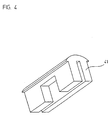
- FIG. 4 the contacting element used in this example is shown in perspective.
- the illustrated embodiment includes only a humidity-sensitive sensor element 44 and no temperature-sensitive sensor element; Of course, this variant could also be supplemented by another temperature-sensitive sensor element, in order to make such a dew point measurement etc ..
- the sensor arrangement 40 again comprises the carrier board 42, on which the moisture-sensitive sensor element 44 is arranged and electrically contacted by connecting lines 46.
- a contacting element in this example now a clip-on plastic sleeve 41 is provided, which is plugged into the contact area between disc 30 and sensor assembly 40 on the support plate 42 with the sensor element 44.
- the plastic sleeve 41 has approximately a T-shaped cross section, wherein the contacting region 41.1 is formed with the disc through the T-cross member.
- the plastic sleeve in the region opposite the sensor element has a recess.
- the sensor element 44 is arranged on the carrier board such that the moisture-sensitive side is oriented away from the carrier board.
- the shape of the plastic sleeve 41 with the recess provided for the sensor element 44 can be seen in particular from the perspective view in FIG.
- a housing 47 is pushed over the plastic sleeve 41 in the T-longitudinal part, so that a mechanically stable overall construction results. Furthermore, this achieves the effect that the plastic sleeve 41 is pressed even more strongly against the metallic connection lines 46 and thus results in a further reduction of the thermal resistance.
- a thermally highly conductive plastic material is used, which is also designed to be electrically insulating.
- a silicone material filled with thermally conductive ceramic material is possible.
- the plastic sleeve 41 is preferably pushed under a certain mechanical tension on the disk 30 facing part of the support plate 42. As a result, the plastic sleeve 41 presses in this area on the connection lines 46 of the sensor element 44. Due to the intimate contact results at this point a small thermal contact resistance. In order to reinforce this effect, it is also advantageous if the connection lines 46 of the sensor element 44 are formed as large as possible and are arranged in the direction of the disk 30. Furthermore, the front side of the carrier board can be metallized for even improved thermal coupling.
- the plastic sleeve is ultimately pressed over a large area against the thermally well-conductive connecting leads 46, whereby at this point the thermal resistance is very low.
- the indentation depth of the elastic material is in this case designed so that different installation depths of the sensor arrangement can be compensated and always the thermal contact with the disc is ensured.
- FIG. 3b A again only slightly modified variant of the second embodiment is shown in Figure 3b in a sectional view.
- bores 150 are arranged in partial areas of the carrier board 142, which are provided with a thermally conductive coating.
- the sensor element 144 is arranged above a recess 149 of the carrier board 142.
- the moisture-sensitive side of the sensor element 144 is oriented in the direction of the recess 149 in this variant.
- the housing 147 further has slots 148 in the region of the recess the corresponding air circulation can take place.
- the plastic sleeve 141 used in this variant further has no recess for the sensor element 144, but is pushed completely over the sensor element 144. This is possible in the present case, since the active or moisture-sensitive side of the sensor element 144 is oriented in the direction of the recess 149 of the carrier board 142.
- the second embodiment with a trained as a plastic sleeve contacting element can be further modified in the context of the present invention.
Claims (16)
- Dispositif de capteur pour la détection de buée sur une vitre, constitué d'une platine support, sur laquelle est disposé au moins un élément capteur sensible à l'humidité, ledit élément capteur étant couplé thermiquement à la vitre,
caractérisé en ce que
pour le couplage thermique de l'élément capteur (24; 44; 124; 144), il est prévu un élément de contact (21; 41; 121; 141) qui est fixé de manière emboîtable à la platine support (22; 42; 122; 142) et entoure en grande partie la platine support (22; 42; 122; 142) dans la zone de contact avec la vitre (10; 30; 110; 130). - Dispositif de capteur selon la revendication 1, caractérisé en ce que l'élément de contact (21; 41; 121; 141), dans la région de l'élément capteur (24; 44; 124; 144), présente un évidement dont les dimensions correspondent à peu près à celles de l'élément capteur (24; 44; 124; 144).
- Dispositif de capteur selon la revendication 1, caractérisé en ce que l'élément de contact (21; 41; 121; 141) est réalisé en un matériau à conductibilité thermique élevée.
- Dispositif de capteur selon la revendication 1, caractérisé en ce que l'élément de contact (21; 41; 121; 141) est élastique et peut être emboîté sous contrainte mécanique sur la platine support (22; 42; 122; 142).
- Dispositif de capteur selon au moins une des revendications 1 à 4, caractérisé en ce que l'élément de contact (21; 121) est constitué d'un ressort métallique.
- Dispositif de capteur selon la revendication 5, caractérisé en ce qu'une couche (25; 125) électriquement isolante mais conductrice de la chaleur est disposée dans la zone de contact entre le ressort métallique et la platine support (22; 122).
- Dispositif de capteur selon la revendication 5, caractérisé en ce qu'une couche (25; 125) électriquement isolante, conductrice de la chaleur est disposée dans la zone de contact entre le ressort métallique et la vitre (10; 110).
- Dispositif de capteur selon la revendication 6 ou 7, caractérisé en ce que la couche (25; 125) électriquement isolante, conductrice de la chaleur est constituée d'un film de polyamide autoadhésif.
- Dispositif de capteur selon la revendication 5, caractérisé en ce que le ressort métallique est réalisé en cuivre, aluminium ou acier à ressorts.
- Dispositif de capteur selon au moins une des revendications 1 à 4, caractérisé en ce que l'élément de contact (41; 141) est composé d'un manchon en matière plastique emboîtable.
- Dispositif de capteur selon la revendication 10, caractérisé en ce que le manchon en matière plastique présente une section en forme de T, la barre transversale du T étant prévue pour le contact avec la vitre (30; 130), et la platine support (42; 142), avec l'élément capteur (44; 144), étant disposée dans la partie verticale du T.
- Dispositif de capteur selon la revendication 10, caractérisé en ce que le manchon en matière plastique se compose d'un matériau silicone rempli avec un matériau céramique thermoconducteur.
- Dispositif de capteur selon la revendication 10, caractérisé en ce que les conducteurs de connexion (46; 146) de l'élément capteur (44; 144) sont réalisés sur une grande surface sur la platine support (42; 142) et disposés en direction de la vitre (30; 130).
- Dispositif de capteur selon au moins une des revendications précédentes, caractérisé en ce que, en plus de l'élément capteur (26; 46; 126; 146) sensible à l'humidité, au nombre d'au moins un, il est prévu au moins un élément capteur sensible à la température sur la platine support (22; 42; 122; 142).
- Dispositif de capteur selon au moins une des revendications précédentes, caractérisé en ce que la platine support (122; 142) présente au moins dans la région de l'élément de contact (121; 141) des perçages (127; 150) qui sont pourvus d'un revêtement thermoconducteur.
- Dispositif de capteur selon au moins une des revendications précédentes, caractérisé en ce que l'élément capteur (124; 144) est monté au-dessus d'un évidement (128; 149) de la platine support (122; 142), la face sensible à l'humidité de l'élément capteur (124; 144) étant orientée en direction de cet évidement (128; 149).
Applications Claiming Priority (1)
| Application Number | Priority Date | Filing Date | Title |
|---|---|---|---|
| DE102005003046A DE102005003046A1 (de) | 2005-01-22 | 2005-01-22 | Sensoranordnung |
Publications (2)
| Publication Number | Publication Date |
|---|---|
| EP1683665A1 EP1683665A1 (fr) | 2006-07-26 |
| EP1683665B1 true EP1683665B1 (fr) | 2007-09-26 |
Family
ID=36190786
Family Applications (1)
| Application Number | Title | Priority Date | Filing Date |
|---|---|---|---|
| EP06000975A Not-in-force EP1683665B1 (fr) | 2005-01-22 | 2006-01-18 | Dispositif de capteur |
Country Status (5)
| Country | Link |
|---|---|
| US (1) | US7405669B2 (fr) |
| EP (1) | EP1683665B1 (fr) |
| JP (1) | JP2006199284A (fr) |
| AT (1) | ATE374125T1 (fr) |
| DE (2) | DE102005003046A1 (fr) |
Families Citing this family (7)
| Publication number | Priority date | Publication date | Assignee | Title |
|---|---|---|---|---|
| EP1700724B1 (fr) * | 2006-07-19 | 2009-09-02 | Sensirion Holding AG | Détecteur d'humidité pour détecter de la buée sur une fenêtre |
| JP5029574B2 (ja) * | 2008-11-12 | 2012-09-19 | 株式会社デンソー | 湿度検出装置、及び湿度検出装置の窓ガラスへの取り付け方法 |
| DE102012015726B4 (de) | 2012-08-08 | 2015-12-10 | S + S Regeltechnik Gmbh | Sensor mit Feuchte-Fühler |
| DE102018113230A1 (de) * | 2018-06-04 | 2019-12-05 | Bcs Automotive Interface Solutions Gmbh | Sensormodul |
| EP3800452B1 (fr) * | 2019-10-04 | 2021-12-15 | MEAS France | Dispositif capteur de température pour pare-brise de véhicule |
| DE102020122803A1 (de) * | 2020-09-01 | 2022-03-03 | Endress+Hauser Flowtec Ag | Messgerät |
| KR102538564B1 (ko) * | 2020-10-20 | 2023-06-01 | 암페놀센싱코리아 유한회사 | 오토 디포그 센서 유닛 |
Family Cites Families (5)
| Publication number | Priority date | Publication date | Assignee | Title |
|---|---|---|---|---|
| JPS6076418A (ja) * | 1983-10-03 | 1985-04-30 | Nippon Denso Co Ltd | 自動車のための結露センサの取付装置 |
| WO2001058731A1 (fr) | 2000-02-11 | 2001-08-16 | E+E Elektronik Ges.M.B.H. | Ensemble capteur |
| DE10152999C2 (de) | 2001-10-26 | 2003-12-24 | Preh Elektro Feinmechanik | Sensor und Sensoreinheit zur Detektion einer Beschlagneigung |
| DE10314018A1 (de) * | 2003-03-28 | 2004-10-07 | Daimlerchrysler Ag | Halterung an einer Windschutzscheibe |
| DE10325971A1 (de) * | 2003-06-07 | 2004-12-23 | E + E Elektronik Ges.M.B.H. | Basismodul für mehrere Sensoreinheiten |
-
2005
- 2005-01-22 DE DE102005003046A patent/DE102005003046A1/de not_active Withdrawn
-
2006
- 2006-01-18 AT AT06000975T patent/ATE374125T1/de not_active IP Right Cessation
- 2006-01-18 US US11/334,335 patent/US7405669B2/en not_active Expired - Fee Related
- 2006-01-18 EP EP06000975A patent/EP1683665B1/fr not_active Not-in-force
- 2006-01-18 DE DE502006000104T patent/DE502006000104D1/de active Active
- 2006-01-20 JP JP2006012454A patent/JP2006199284A/ja not_active Withdrawn
Non-Patent Citations (1)
| Title |
|---|
| None * |
Also Published As
| Publication number | Publication date |
|---|---|
| ATE374125T1 (de) | 2007-10-15 |
| US7405669B2 (en) | 2008-07-29 |
| US20060176184A1 (en) | 2006-08-10 |
| DE502006000104D1 (de) | 2007-11-08 |
| DE102005003046A1 (de) | 2006-07-27 |
| JP2006199284A (ja) | 2006-08-03 |
| EP1683665A1 (fr) | 2006-07-26 |
Similar Documents
| Publication | Publication Date | Title |
|---|---|---|
| EP1683665B1 (fr) | Dispositif de capteur | |
| DE102005016896B3 (de) | Sensoranordnung zur Temperaturmessung | |
| EP1380481B1 (fr) | Dispositif capteur | |
| DE102005038466B4 (de) | Sensoranordnung zur Temperaturmessung | |
| EP1559195A1 (fr) | Detecteur capacitif d'approche et/ou de contact et corps en plastique electriquement conducteur pour un detecteur de ce type | |
| EP1306242B1 (fr) | Capteur de détection d'une tendance à s'embuer et module de capteur | |
| EP1605238B1 (fr) | Distributeur électronique de frais de chauffage | |
| WO2007009767A2 (fr) | Capteur de pluie capacitif | |
| DE102006019895A1 (de) | Strommessvorrichtung mit speziell kontaktierter Leiterplatte und entsprechendes Herstellungsverfahren | |
| EP1936342A1 (fr) | Agencement de capteur destiné à la mesure de la température | |
| EP3615903B1 (fr) | Capteur de détection d'un profil de température spatial et procédé de fabrication d'une unité de détection | |
| DE19504572C2 (de) | Temperaturfühleranordnung | |
| DE102010030769B4 (de) | Temperaturfühler zur Messung einer Fahrzeuginnentemperatur | |
| EP1598224B1 (fr) | Dispositif de détection de buée sur une surface d'un véhicule | |
| EP1636055B1 (fr) | Module de base destine a plusieurs unites de capteurs | |
| EP1951535B1 (fr) | Detecteur de buee | |
| EP3058314B1 (fr) | Élément détecteur | |
| DE102018113230A1 (de) | Sensormodul | |
| DE102008040186B4 (de) | Trägerstruktur für ein Kombiinstrument, Kombiinstrument und Kraftfahrzeug | |
| DE102006047695B4 (de) | Elektronisches Modul zum Steuern eines Personen- und/oder Insassenschutzsystems eines Fahrzeugs | |
| DE202004007802U1 (de) | Elektronischer Heizkostenverteiler | |
| DE202014003413U1 (de) | Vorrichtung zum elektronischen Erfassen der Wärmeabgabe eines Heizkörpers |
Legal Events
| Date | Code | Title | Description |
|---|---|---|---|
| PUAI | Public reference made under article 153(3) epc to a published international application that has entered the european phase |
Free format text: ORIGINAL CODE: 0009012 |
|
| AK | Designated contracting states |
Kind code of ref document: A1 Designated state(s): AT BE BG CH CY CZ DE DK EE ES FI FR GB GR HU IE IS IT LI LT LU LV MC NL PL PT RO SE SI SK TR |
|
| AX | Request for extension of the european patent |
Extension state: AL BA HR MK YU |
|
| GRAP | Despatch of communication of intention to grant a patent |
Free format text: ORIGINAL CODE: EPIDOSNIGR1 |
|
| 17P | Request for examination filed |
Effective date: 20070126 |
|
| AKX | Designation fees paid |
Designated state(s): AT BE BG CH CY CZ DE DK EE ES FI FR GB GR HU IE IS IT LI LT LU LV MC NL PL PT RO SE SI SK TR |
|
| GRAS | Grant fee paid |
Free format text: ORIGINAL CODE: EPIDOSNIGR3 |
|
| GRAA | (expected) grant |
Free format text: ORIGINAL CODE: 0009210 |
|
| AK | Designated contracting states |
Kind code of ref document: B1 Designated state(s): AT BE BG CH CY CZ DE DK EE ES FI FR GB GR HU IE IS IT LI LT LU LV MC NL PL PT RO SE SI SK TR |
|
| REG | Reference to a national code |
Ref country code: GB Ref legal event code: FG4D Free format text: NOT ENGLISH |
|
| REG | Reference to a national code |
Ref country code: CH Ref legal event code: EP |
|
| REF | Corresponds to: |
Ref document number: 502006000104 Country of ref document: DE Date of ref document: 20071108 Kind code of ref document: P |
|
| REG | Reference to a national code |
Ref country code: IE Ref legal event code: FG4D Free format text: LANGUAGE OF EP DOCUMENT: GERMAN |
|
| PG25 | Lapsed in a contracting state [announced via postgrant information from national office to epo] |
Ref country code: LT Free format text: LAPSE BECAUSE OF FAILURE TO SUBMIT A TRANSLATION OF THE DESCRIPTION OR TO PAY THE FEE WITHIN THE PRESCRIBED TIME-LIMIT Effective date: 20070926 Ref country code: FI Free format text: LAPSE BECAUSE OF FAILURE TO SUBMIT A TRANSLATION OF THE DESCRIPTION OR TO PAY THE FEE WITHIN THE PRESCRIBED TIME-LIMIT Effective date: 20070926 |
|
| PG25 | Lapsed in a contracting state [announced via postgrant information from national office to epo] |
Ref country code: PL Free format text: LAPSE BECAUSE OF FAILURE TO SUBMIT A TRANSLATION OF THE DESCRIPTION OR TO PAY THE FEE WITHIN THE PRESCRIBED TIME-LIMIT Effective date: 20070926 |
|
| NLV1 | Nl: lapsed or annulled due to failure to fulfill the requirements of art. 29p and 29m of the patents act | ||
| PG25 | Lapsed in a contracting state [announced via postgrant information from national office to epo] |
Ref country code: LV Free format text: LAPSE BECAUSE OF FAILURE TO SUBMIT A TRANSLATION OF THE DESCRIPTION OR TO PAY THE FEE WITHIN THE PRESCRIBED TIME-LIMIT Effective date: 20070926 |
|
| GBV | Gb: ep patent (uk) treated as always having been void in accordance with gb section 77(7)/1977 [no translation filed] | ||
| PG25 | Lapsed in a contracting state [announced via postgrant information from national office to epo] |
Ref country code: ES Free format text: LAPSE BECAUSE OF FAILURE TO SUBMIT A TRANSLATION OF THE DESCRIPTION OR TO PAY THE FEE WITHIN THE PRESCRIBED TIME-LIMIT Effective date: 20080106 Ref country code: GR Free format text: LAPSE BECAUSE OF FAILURE TO SUBMIT A TRANSLATION OF THE DESCRIPTION OR TO PAY THE FEE WITHIN THE PRESCRIBED TIME-LIMIT Effective date: 20071227 Ref country code: NL Free format text: LAPSE BECAUSE OF FAILURE TO SUBMIT A TRANSLATION OF THE DESCRIPTION OR TO PAY THE FEE WITHIN THE PRESCRIBED TIME-LIMIT Effective date: 20070926 |
|
| REG | Reference to a national code |
Ref country code: IE Ref legal event code: FD4D |
|
| PG25 | Lapsed in a contracting state [announced via postgrant information from national office to epo] |
Ref country code: IS Free format text: LAPSE BECAUSE OF FAILURE TO SUBMIT A TRANSLATION OF THE DESCRIPTION OR TO PAY THE FEE WITHIN THE PRESCRIBED TIME-LIMIT Effective date: 20080126 Ref country code: PT Free format text: LAPSE BECAUSE OF FAILURE TO SUBMIT A TRANSLATION OF THE DESCRIPTION OR TO PAY THE FEE WITHIN THE PRESCRIBED TIME-LIMIT Effective date: 20080226 Ref country code: CZ Free format text: LAPSE BECAUSE OF FAILURE TO SUBMIT A TRANSLATION OF THE DESCRIPTION OR TO PAY THE FEE WITHIN THE PRESCRIBED TIME-LIMIT Effective date: 20070926 Ref country code: SK Free format text: LAPSE BECAUSE OF FAILURE TO SUBMIT A TRANSLATION OF THE DESCRIPTION OR TO PAY THE FEE WITHIN THE PRESCRIBED TIME-LIMIT Effective date: 20070926 |
|
| PG25 | Lapsed in a contracting state [announced via postgrant information from national office to epo] |
Ref country code: SE Free format text: LAPSE BECAUSE OF FAILURE TO SUBMIT A TRANSLATION OF THE DESCRIPTION OR TO PAY THE FEE WITHIN THE PRESCRIBED TIME-LIMIT Effective date: 20071226 Ref country code: RO Free format text: LAPSE BECAUSE OF FAILURE TO SUBMIT A TRANSLATION OF THE DESCRIPTION OR TO PAY THE FEE WITHIN THE PRESCRIBED TIME-LIMIT Effective date: 20070926 |
|
| EN | Fr: translation not filed | ||
| BERE | Be: lapsed |
Owner name: E+E ELEKTRONIK GES.M.B.H. Effective date: 20080131 |
|
| PG25 | Lapsed in a contracting state [announced via postgrant information from national office to epo] |
Ref country code: DK Free format text: LAPSE BECAUSE OF FAILURE TO SUBMIT A TRANSLATION OF THE DESCRIPTION OR TO PAY THE FEE WITHIN THE PRESCRIBED TIME-LIMIT Effective date: 20070926 |
|
| PLBE | No opposition filed within time limit |
Free format text: ORIGINAL CODE: 0009261 |
|
| STAA | Information on the status of an ep patent application or granted ep patent |
Free format text: STATUS: NO OPPOSITION FILED WITHIN TIME LIMIT |
|
| PG25 | Lapsed in a contracting state [announced via postgrant information from national office to epo] |
Ref country code: MC Free format text: LAPSE BECAUSE OF NON-PAYMENT OF DUE FEES Effective date: 20080131 |
|
| 26N | No opposition filed |
Effective date: 20080627 |
|
| PG25 | Lapsed in a contracting state [announced via postgrant information from national office to epo] |
Ref country code: FR Free format text: LAPSE BECAUSE OF FAILURE TO SUBMIT A TRANSLATION OF THE DESCRIPTION OR TO PAY THE FEE WITHIN THE PRESCRIBED TIME-LIMIT Effective date: 20080704 Ref country code: IE Free format text: LAPSE BECAUSE OF FAILURE TO SUBMIT A TRANSLATION OF THE DESCRIPTION OR TO PAY THE FEE WITHIN THE PRESCRIBED TIME-LIMIT Effective date: 20070926 |
|
| PG25 | Lapsed in a contracting state [announced via postgrant information from national office to epo] |
Ref country code: GB Free format text: LAPSE BECAUSE OF FAILURE TO SUBMIT A TRANSLATION OF THE DESCRIPTION OR TO PAY THE FEE WITHIN THE PRESCRIBED TIME-LIMIT Effective date: 20070926 |
|
| PG25 | Lapsed in a contracting state [announced via postgrant information from national office to epo] |
Ref country code: EE Free format text: LAPSE BECAUSE OF FAILURE TO SUBMIT A TRANSLATION OF THE DESCRIPTION OR TO PAY THE FEE WITHIN THE PRESCRIBED TIME-LIMIT Effective date: 20070926 |
|
| PG25 | Lapsed in a contracting state [announced via postgrant information from national office to epo] |
Ref country code: BE Free format text: LAPSE BECAUSE OF NON-PAYMENT OF DUE FEES Effective date: 20080131 |
|
| PG25 | Lapsed in a contracting state [announced via postgrant information from national office to epo] |
Ref country code: AT Free format text: LAPSE BECAUSE OF NON-PAYMENT OF DUE FEES Effective date: 20080118 |
|
| PG25 | Lapsed in a contracting state [announced via postgrant information from national office to epo] |
Ref country code: SI Free format text: LAPSE BECAUSE OF FAILURE TO SUBMIT A TRANSLATION OF THE DESCRIPTION OR TO PAY THE FEE WITHIN THE PRESCRIBED TIME-LIMIT Effective date: 20070926 |
|
| PG25 | Lapsed in a contracting state [announced via postgrant information from national office to epo] |
Ref country code: CY Free format text: LAPSE BECAUSE OF FAILURE TO SUBMIT A TRANSLATION OF THE DESCRIPTION OR TO PAY THE FEE WITHIN THE PRESCRIBED TIME-LIMIT Effective date: 20070926 |
|
| PG25 | Lapsed in a contracting state [announced via postgrant information from national office to epo] |
Ref country code: BG Free format text: LAPSE BECAUSE OF FAILURE TO SUBMIT A TRANSLATION OF THE DESCRIPTION OR TO PAY THE FEE WITHIN THE PRESCRIBED TIME-LIMIT Effective date: 20071226 |
|
| PG25 | Lapsed in a contracting state [announced via postgrant information from national office to epo] |
Ref country code: LU Free format text: LAPSE BECAUSE OF NON-PAYMENT OF DUE FEES Effective date: 20080118 Ref country code: HU Free format text: LAPSE BECAUSE OF FAILURE TO SUBMIT A TRANSLATION OF THE DESCRIPTION OR TO PAY THE FEE WITHIN THE PRESCRIBED TIME-LIMIT Effective date: 20080327 |
|
| PG25 | Lapsed in a contracting state [announced via postgrant information from national office to epo] |
Ref country code: TR Free format text: LAPSE BECAUSE OF FAILURE TO SUBMIT A TRANSLATION OF THE DESCRIPTION OR TO PAY THE FEE WITHIN THE PRESCRIBED TIME-LIMIT Effective date: 20070926 |
|
| REG | Reference to a national code |
Ref country code: CH Ref legal event code: PL |
|
| PG25 | Lapsed in a contracting state [announced via postgrant information from national office to epo] |
Ref country code: LI Free format text: LAPSE BECAUSE OF NON-PAYMENT OF DUE FEES Effective date: 20100131 Ref country code: CH Free format text: LAPSE BECAUSE OF NON-PAYMENT OF DUE FEES Effective date: 20100131 |
|
| PG25 | Lapsed in a contracting state [announced via postgrant information from national office to epo] |
Ref country code: IT Free format text: LAPSE BECAUSE OF NON-PAYMENT OF DUE FEES Effective date: 20080131 |
|
| PGFP | Annual fee paid to national office [announced via postgrant information from national office to epo] |
Ref country code: DE Payment date: 20210120 Year of fee payment: 16 |
|
| REG | Reference to a national code |
Ref country code: DE Ref legal event code: R119 Ref document number: 502006000104 Country of ref document: DE |
|
| PG25 | Lapsed in a contracting state [announced via postgrant information from national office to epo] |
Ref country code: DE Free format text: LAPSE BECAUSE OF NON-PAYMENT OF DUE FEES Effective date: 20220802 |