EP1683665B1 - Sensor system - Google Patents
Sensor system Download PDFInfo
- Publication number
- EP1683665B1 EP1683665B1 EP06000975A EP06000975A EP1683665B1 EP 1683665 B1 EP1683665 B1 EP 1683665B1 EP 06000975 A EP06000975 A EP 06000975A EP 06000975 A EP06000975 A EP 06000975A EP 1683665 B1 EP1683665 B1 EP 1683665B1
- Authority
- EP
- European Patent Office
- Prior art keywords
- arrangement according
- sensor arrangement
- sensor
- sensor element
- supporting plate
- Prior art date
- Legal status (The legal status is an assumption and is not a legal conclusion. Google has not performed a legal analysis and makes no representation as to the accuracy of the status listed.)
- Not-in-force
Links
- 230000008878 coupling Effects 0.000 claims abstract description 19
- 238000010168 coupling process Methods 0.000 claims abstract description 19
- 238000005859 coupling reaction Methods 0.000 claims abstract description 19
- 229910052751 metal Inorganic materials 0.000 claims description 22
- 239000002184 metal Substances 0.000 claims description 22
- 239000004033 plastic Substances 0.000 claims description 19
- 229920003023 plastic Polymers 0.000 claims description 19
- 239000000463 material Substances 0.000 claims description 7
- 239000011248 coating agent Substances 0.000 claims description 3
- 238000000576 coating method Methods 0.000 claims description 3
- 238000001514 detection method Methods 0.000 claims description 3
- RYGMFSIKBFXOCR-UHFFFAOYSA-N Copper Chemical compound [Cu] RYGMFSIKBFXOCR-UHFFFAOYSA-N 0.000 claims description 2
- 229910000639 Spring steel Inorganic materials 0.000 claims description 2
- 239000000853 adhesive Substances 0.000 claims description 2
- 229910052782 aluminium Inorganic materials 0.000 claims description 2
- XAGFODPZIPBFFR-UHFFFAOYSA-N aluminium Chemical compound [Al] XAGFODPZIPBFFR-UHFFFAOYSA-N 0.000 claims description 2
- 229910010293 ceramic material Inorganic materials 0.000 claims description 2
- 229910052802 copper Inorganic materials 0.000 claims description 2
- 239000010949 copper Substances 0.000 claims description 2
- 229920001296 polysiloxane Polymers 0.000 claims description 2
- 239000004952 Polyamide Substances 0.000 claims 1
- 239000004411 aluminium Substances 0.000 claims 1
- 239000003595 mist Substances 0.000 claims 1
- 229920002647 polyamide Polymers 0.000 claims 1
- 239000010408 film Substances 0.000 description 4
- 239000011888 foil Substances 0.000 description 4
- 238000005259 measurement Methods 0.000 description 3
- 239000002313 adhesive film Substances 0.000 description 2
- 239000012080 ambient air Substances 0.000 description 2
- 239000004020 conductor Substances 0.000 description 2
- 230000000694 effects Effects 0.000 description 2
- 238000009434 installation Methods 0.000 description 2
- BASFCYQUMIYNBI-UHFFFAOYSA-N platinum Chemical compound [Pt] BASFCYQUMIYNBI-UHFFFAOYSA-N 0.000 description 2
- 239000010409 thin film Substances 0.000 description 2
- 239000004642 Polyimide Substances 0.000 description 1
- 239000003570 air Substances 0.000 description 1
- 238000004378 air conditioning Methods 0.000 description 1
- 238000009529 body temperature measurement Methods 0.000 description 1
- 238000010276 construction Methods 0.000 description 1
- 230000001419 dependent effect Effects 0.000 description 1
- 239000013013 elastic material Substances 0.000 description 1
- 238000010438 heat treatment Methods 0.000 description 1
- 238000007373 indentation Methods 0.000 description 1
- 150000002739 metals Chemical class 0.000 description 1
- 229910052697 platinum Inorganic materials 0.000 description 1
- 229920001721 polyimide Polymers 0.000 description 1
Images


Classifications
-
- B—PERFORMING OPERATIONS; TRANSPORTING
- B60—VEHICLES IN GENERAL
- B60H—ARRANGEMENTS OF HEATING, COOLING, VENTILATING OR OTHER AIR-TREATING DEVICES SPECIALLY ADAPTED FOR PASSENGER OR GOODS SPACES OF VEHICLES
- B60H1/00—Heating, cooling or ventilating [HVAC] devices
- B60H1/00642—Control systems or circuits; Control members or indication devices for heating, cooling or ventilating devices
- B60H1/00735—Control systems or circuits characterised by their input, i.e. by the detection, measurement or calculation of particular conditions, e.g. signal treatment, dynamic models
- B60H1/00785—Control systems or circuits characterised by their input, i.e. by the detection, measurement or calculation of particular conditions, e.g. signal treatment, dynamic models by the detection of humidity or frost
Definitions
- the present invention relates to a sensor arrangement for detecting fogging on a pane according to the preamble of claim 1. Particularly suitable is the inventive sensor arrangement for detecting fogging on a motor vehicle windshield.
- Suitable sensor arrangements for fog detection on motor vehicle windshields are approximately from the WO 01/58731 or from the EP 1 306 242 A1 known.
- arrangements are respectively proposed which comprise a moisture-sensitive sensor element arranged on a carrier board.
- a capacitive thin-film sensor is preferably provided.
- the sensor element is thermally coupled to the disk and thus to the disk temperature. The thermal coupling takes place via a thin adhesive film. About the adhesive film, the sensor assembly is further attached to the disc.
- DE-10325971 discloses a sensor arrangement according to the preamble of claim 1.
- Object of the present invention is to provide a sensor arrangement for detecting fog on a disc, which ensures a good thermal coupling between the disc and sensor element even under unfavorable cultivation conditions.
- a contacting element for the thermal coupling of the sensor element which is attachable to the carrier board and largely encloses the carrier board in the area of contact with the pane.
- the respective contacting element is preferably pushed onto the carrier board under mechanical tension in order to improve the thermal coupling.
- the carrier board is a large area in contact with the disc and this is arranged parallel to the disc. Due to the provided Maisticianselements an arrangement of the carrier board in relation to the disc is possible, in which the carrier board is arranged, for example, oriented perpendicular or at an arbitrary angle to the disc. This allows a space-saving design of the entire sensor assembly, while the heat coupling of the sensor element remains ensured.
- the contacting element has a recess in the region of the sensor element which corresponds to the dimensions of the sensor element. Furthermore, there is the contacting element used with advantage of a material with high thermal conductivity; Furthermore, this preferably also has a certain elasticity.
- a contacting element is for example a U-shaped metal spring or a T-shaped plastic sleeve into consideration. In both cases, the contacting element can be plugged onto the carrier board.
- the sensor arrangement according to the invention can have as sensor element only a moisture-sensitive sensor element by means of which the relative humidity in the vicinity of the pane is detected as a measure of fogging tendency.
- a temperature-sensitive sensor element may additionally be provided in addition to the moisture-sensitive sensor element in order to further perform a dew point measurement in this way.
- FIGS. 1, 2a and 2b A first embodiment of the sensor arrangement according to the invention, including a slightly modified variant thereof, will now be described with reference to FIGS. 1, 2a and 2b. While FIG. 1 shows a perspective view of the sensor arrangement 20 in conjunction with a part of a pane 10, FIG. 2 a shows a sectional view of the sensor arrangement 20 from FIG.
- the disc 10 may be approximately the windshield of a motor vehicle, on the inside of which the sensor arrangement 20 according to the invention for fitting detection is arranged. About the sensor assembly 20, the incipient fogging tendency is detected on this disc 10 and the corresponding signals used to take by means of the heating and / or air conditioning suitable countermeasures.
- the thermal coupling of the sensor arrangement 20 to the disk 10 takes place in the present example via a contacting element in the form of a metal spring 21, which is plugged onto the carrier board 22 in the contact area with the disk 10.
- a suitable material for the metal spring 21 are generally good heat conducting metals into consideration, such as Copper, aluminum or spring steel.
- the moisture-sensitive sensor element 24 is also indicated in a schematic form.
- the moisture-sensitive sensor element 24 is formed in a known manner as a capacitive thin-film sensor; In the case of using an additional temperature-sensitive sensor element, for example, a known resisitive element, such as a platinum resistance element, can be used for this purpose.
- FIG. 2 shows the connecting lines for the sensor element 24 and in this case provided with the reference number 26; Further interconnects and electronic components on the carrier board 22 are not shown in the figures for reasons of clarity.
- the contacting element or the metal spring 21 largely encloses the carrier board 2 in the area of contact with the pane 10. Only in the region of the sensor element 24 has the metal spring 21 a recess which corresponds approximately to the dimensions of the sensor element 24 on the carrier board 22. About the recess is ensured that the sensor element 24 is in exchange with the ambient air.
- a heat-conductive, electrically insulating layer in the form of a thin heat-conducting film 25 is arranged on the inside of the metal spring 21, which faces the carrier board 22, also a heat-conductive, electrically insulating layer in the form of a thin heat-conducting film 25 is arranged.
- the heat-conducting foil used is preferably a self-adhesive polyimide foil having a thickness of between 50 ⁇ m and 200 ⁇ m.
- another glued or sprayed insulating layer can be arranged at this point as an electrically insulating layer.
- the heat conducting film 25 is further arranged on a contacting part 21.1 of the metal spring 21, which represents the contact area between the metal spring 21 and the disk 10.
- the heat-conducting foil 25 is between the contacting part 21.1 and the disc 10 is arranged.
- the contacting part 21.1 is formed in this example as an extension of the metal spring 21 at its U-end and extends along the Suplatinenkante, which is oriented in the direction of disk 10.
- the heat flow between the disk 10 and sensor element 24 extends in the illustrated example of the disc 10 via the heat-conducting foil 25 on the contacting part 21.1, the metal spring 21, the heat-conducting film 25, the connecting lines 26 to the sensor element 24.
- the metal spring has the greatest influence on the thermal coupling 21st
- Both the disk 10 and the carrier board 22 are contacted in the illustrated embodiment only by the heat-conducting film 25. On the side of the disc 10 is thereby ensured that the disc 10 is not scratched by the metal spring 21. On the side of the carrier board 22, an electrical short circuit between a plurality of conductor tracks or connecting lines 26 of the sensor element 24 is avoided, but at the same time a good thermal coupling of all connection lines 26 of the sensor element is ensured.
- FIG. 2b A variant of the first exemplary embodiment of the sensor arrangement according to the invention which is slightly modified with respect to the exemplary embodiment in FIG. 2a is shown in a sectional view in FIG. 2b. In the following, only the differences, for example in FIG. 2a, will be discussed.
- this variant it is provided in this variant to arrange the sensor element 124 over a recess 128 of the carrier board 122, as likewise shown in FIG WO 01/58731 A1 was proposed.
- This mounting variant for the sensor element 124 proves to be advantageous if the moisture-sensitive or active side of the sensor element 124 is oriented in the direction of the carrier board 122.
- a mounting of the sensor element 24 is provided, in which the moisture-sensitive side of the support plate 22 is oriented away.
- the illustrated first embodiment with a trained as a metal spring contacting element can of course be further modified in the context of the present invention. Mention would be about an embodiment of the metal spring such that it laterally clasps the carrier board. Furthermore, the contacting part 21.1 could also be formed bent over the U-shaped part of the metal spring, etc.
- FIGS. 3 a, 3 b and 4 including a slightly modified variant thereof.
- FIG. 3 a shows a sectional view of a second embodiment of the sensor arrangement according to the invention in conjunction with a pane
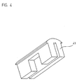
- FIG. 4 the contacting element used in this example is shown in perspective.
- the illustrated embodiment includes only a humidity-sensitive sensor element 44 and no temperature-sensitive sensor element; Of course, this variant could also be supplemented by another temperature-sensitive sensor element, in order to make such a dew point measurement etc ..
- the sensor arrangement 40 again comprises the carrier board 42, on which the moisture-sensitive sensor element 44 is arranged and electrically contacted by connecting lines 46.
- a contacting element in this example now a clip-on plastic sleeve 41 is provided, which is plugged into the contact area between disc 30 and sensor assembly 40 on the support plate 42 with the sensor element 44.
- the plastic sleeve 41 has approximately a T-shaped cross section, wherein the contacting region 41.1 is formed with the disc through the T-cross member.
- the plastic sleeve in the region opposite the sensor element has a recess.
- the sensor element 44 is arranged on the carrier board such that the moisture-sensitive side is oriented away from the carrier board.
- the shape of the plastic sleeve 41 with the recess provided for the sensor element 44 can be seen in particular from the perspective view in FIG.
- a housing 47 is pushed over the plastic sleeve 41 in the T-longitudinal part, so that a mechanically stable overall construction results. Furthermore, this achieves the effect that the plastic sleeve 41 is pressed even more strongly against the metallic connection lines 46 and thus results in a further reduction of the thermal resistance.
- a thermally highly conductive plastic material is used, which is also designed to be electrically insulating.
- a silicone material filled with thermally conductive ceramic material is possible.
- the plastic sleeve 41 is preferably pushed under a certain mechanical tension on the disk 30 facing part of the support plate 42. As a result, the plastic sleeve 41 presses in this area on the connection lines 46 of the sensor element 44. Due to the intimate contact results at this point a small thermal contact resistance. In order to reinforce this effect, it is also advantageous if the connection lines 46 of the sensor element 44 are formed as large as possible and are arranged in the direction of the disk 30. Furthermore, the front side of the carrier board can be metallized for even improved thermal coupling.
- the plastic sleeve is ultimately pressed over a large area against the thermally well-conductive connecting leads 46, whereby at this point the thermal resistance is very low.
- the indentation depth of the elastic material is in this case designed so that different installation depths of the sensor arrangement can be compensated and always the thermal contact with the disc is ensured.
- FIG. 3b A again only slightly modified variant of the second embodiment is shown in Figure 3b in a sectional view.
- bores 150 are arranged in partial areas of the carrier board 142, which are provided with a thermally conductive coating.
- the sensor element 144 is arranged above a recess 149 of the carrier board 142.
- the moisture-sensitive side of the sensor element 144 is oriented in the direction of the recess 149 in this variant.
- the housing 147 further has slots 148 in the region of the recess the corresponding air circulation can take place.
- the plastic sleeve 141 used in this variant further has no recess for the sensor element 144, but is pushed completely over the sensor element 144. This is possible in the present case, since the active or moisture-sensitive side of the sensor element 144 is oriented in the direction of the recess 149 of the carrier board 142.
- the second embodiment with a trained as a plastic sleeve contacting element can be further modified in the context of the present invention.
Abstract
Description
Die vorliegende Erfindung betrifft eine Sensoranordnung zur Beschlagsdetektion an einer Scheibe gemäß dem Oberbegriff des Anspruches 1. Insbesondere geeignet ist erfindungsgemäße Sensoranordnung zur Beschlagsdetektion an einer Kraftfahrzeug-Windschutzscheibe.The present invention relates to a sensor arrangement for detecting fogging on a pane according to the preamble of claim 1. Particularly suitable is the inventive sensor arrangement for detecting fogging on a motor vehicle windshield.
Geeignete Sensoranordnungen zur Beschlagsdetektion an Kraftfahrzeug-Windschutzscheiben sind etwa aus der
Wichtig für die Funktion der Sensoranordnung ist deren thermische Ankopplung an die Scheibe. Ideal wäre für eine gute thermische Ankopplung ein möglichst großflächiger Kontaktbereich zwischen der Sensoranordnung und der Scheibe. Dies ist jedoch in vielen Fällen aufgrund des zur Verfügung stehenden Bauraumes nicht realisierbar. Oftmals steht lediglich eine kleine Kontaktfläche zwischen der Sensoranordnung und der Scheibe zur Verfügung, was im Hinblick auf eine gute thermische Kopplung problematisch ist.Important for the function of the sensor arrangement is their thermal coupling to the disk. Ideally, for a good thermal coupling, the largest possible area of contact between the sensor arrangement and the pane would be. However, this is not feasible in many cases due to the available space. Often there is only a small one Contact surface between the sensor assembly and the disc available, which is problematic in terms of good thermal coupling.
Aufgabe der vorliegenden Erfindung ist es, eine Sensoranordnung zur Beschlagsdetektion an einer Scheibe anzugeben, die auch unter ungünstigen Anbaubedingungen eine gute thermische Kopplung zwischen Scheibe und Sensorelement gewährleistet.Object of the present invention is to provide a sensor arrangement for detecting fog on a disc, which ensures a good thermal coupling between the disc and sensor element even under unfavorable cultivation conditions.
Diese Aufgabe wird gelöst durch eine Sensoranordnung mit den Merkmalen des Anspruches 1.This object is achieved by a sensor arrangement having the features of claim 1.
Vorteilhafte Ausführungsformen der erfindungsgemäßen Sensoranordnung ergeben sich aus den Maßnahmen in den abhängigen Patentansprüchen.Advantageous embodiments of the sensor arrangement according to the invention emerge from the measures in the dependent claims.
Erfindungsgemäß ist nunmehr vorgesehen, zur thermischen Ankopplung des Sensorelementes ein Kontaktierungselement vorzusehen, das aufsteckbar an der Trägerplatine befestigt ist und die Trägerplatine im Kontaktbereich zur Scheibe weitgehend umschließt. Vorzugsweise wird das jeweilige Kontaktierungselement hierbei unter mechanischer Spannung auf die Trägerplatine aufgeschoben, um die thermische Kopplung zu verbessern.According to the invention, it is now provided to provide a contacting element for the thermal coupling of the sensor element, which is attachable to the carrier board and largely encloses the carrier board in the area of contact with the pane. In this case, the respective contacting element is preferably pushed onto the carrier board under mechanical tension in order to improve the thermal coupling.
Es ist nunmehr nicht mehr erforderlich, dass die Trägerplatine großflächig in Kontakt mit der Scheibe ist und hierzu parallel zur Scheibe angeordnet ist. Aufgrund des vorgesehenen Kontaktierungselements ist eine Anordnung der Trägerplatine in Bezug auf die Scheibe möglich, bei der die Trägerplatine beispielsweise senkrecht oder in einem beliebigen Winkel zur Scheibe orientiert angeordnet ist. Dies gestattet eine platzsparende Ausführung der gesamten Sensoranordnung, wobei gleichzeitig die Wärmeankopplung des Sensorelements gewährleistet bleibt.It is now no longer necessary that the carrier board is a large area in contact with the disc and this is arranged parallel to the disc. Due to the provided Kontaktierungselements an arrangement of the carrier board in relation to the disc is possible, in which the carrier board is arranged, for example, oriented perpendicular or at an arbitrary angle to the disc. This allows a space-saving design of the entire sensor assembly, while the heat coupling of the sensor element remains ensured.
In einer möglichen Ausführungsform besitzt das Kontaktierungselement im Bereich des Sensorelements eine Ausnehmung, die den Abmessungen des Sensorelements entspricht. Ferner besteht das verwendete Kontaktierungselement mit Vorteil aus einem Material mit hoher Wärmeleitfähigkeit; ferner weist dieses vorzugsweise auch eine gewisse Elastizität auf.In one possible embodiment, the contacting element has a recess in the region of the sensor element which corresponds to the dimensions of the sensor element. Furthermore, there is the contacting element used with advantage of a material with high thermal conductivity; Furthermore, this preferably also has a certain elasticity.
Als Kontaktierungselement kommt beispielsweise eine U-förmige Metallfeder oder aber eine T-förmige Kunststoff-Hülse in Betracht. In beiden Fällen ist das Kontaktierungselement auf die Trägerplatine aufsteckbar.As a contacting element is for example a U-shaped metal spring or a T-shaped plastic sleeve into consideration. In both cases, the contacting element can be plugged onto the carrier board.
In beiden Ausführungsformen lässt sich somit trotz einer nur kleinen Kontaktfläche zwischen Sensoranordnung und Scheibe eine sehr gute thermische Kopplung zwischen dem Sensorelement und der Scheibe sicherstellen. Es resultiert ein lediglich geringer thermischer Widerstand zwischen der Sensoranordnung und der Scheibe und daraus wiederum eine hinreichende Messgenauigkeit.In both embodiments, it is thus possible to ensure a very good thermal coupling between the sensor element and the pane despite a small contact area between the sensor arrangement and the pane. This results in only a low thermal resistance between the sensor arrangement and the disk and, in turn, a sufficient accuracy of measurement.
Aufgrund der vorzugsweise elastischen Ausgestaltung des Kontaktierungselements können zudem bestimmte Ein- und Anbautoleranzen für die Sensoranordnung ausgeglichen werden, beispielsweise Entfernungsunterschiede zwischen Sensorelement und Scheibe oder aber die erforderliche Winkelausrichtung zwischen Sensorelement und Scheibe.Due to the preferably elastic configuration of the contacting element also certain mounting and mounting tolerances for the sensor arrangement can be compensated, for example, distance differences between the sensor element and the disc or the required angular alignment between the sensor element and disc.
Grundsätzlich kann die erfindungsgemäße Sensoranordnung als Sensorelement lediglich ein feuchteempfindliches Sensorelement aufweisen, mittels dem die relative Feuchte in Scheibennähe als Maß für eine Beschlagsneigung erfasst wird. In einer etwas aufwändigeren Variante kann neben dem feuchteempfindlichen Sensorelement zusätzlich noch ein temperaturempfindliches Sensorelement vorgesehen sein, um dergestalt ferner eine Taupunktmessung vorzunehmen. Dadurch kann über die ermittelte Temperatur im Fahrzeuginneren auch auf das Klima im Fahrzeug-Innenraum, insbesondere die dort herrschende relative Feuchte, rückgeschlossen werden. In beiden Fällen gewährleisten die erfindungsgemäßen Maßnahmen eine gute thermische Ankopplung des bzw. der eingesetzten Sensorelemente an die Scheibe.In principle, the sensor arrangement according to the invention can have as sensor element only a moisture-sensitive sensor element by means of which the relative humidity in the vicinity of the pane is detected as a measure of fogging tendency. In a somewhat more elaborate variant, a temperature-sensitive sensor element may additionally be provided in addition to the moisture-sensitive sensor element in order to further perform a dew point measurement in this way. As a result, conclusions about the determined temperature in the vehicle interior and the climate in the vehicle interior, in particular the prevailing relative humidity there, can be deduced. In both cases, the measures according to the invention ensure good thermal coupling of the sensor element (s) used to the disk.
Als vorteilhafte Maßnahme zur optimierten thermischen Kopplung erweist sich ferner für alle Ausführungsvarianten, wenn der Abstand zwischen dem Sensorelement und der Scheibe möglichst minimiert wird.As an advantageous measure for optimized thermal coupling also proves for all variants, if the distance between the sensor element and the disc is minimized.
Weitere Vorteile sowie Einzelheiten der erfindungsgemäßen Sensoranordnung ergeben sich aus der nachfolgenden Beschreibung von Ausführungsbeispielen anhand der beiliegenden Figuren.Further advantages and details of the sensor arrangement according to the invention will become apparent from the following description of embodiments with reference to the accompanying figures.
- Figur 1FIG. 1
- eine perspektivische Darstellung einer ersten Ausführungsform der erfindungsgemäßen Sensoranordnung in Verbindung mit einer Scheibe;a perspective view of a first embodiment of the sensor arrangement according to the invention in conjunction with a disc;
- Figur 2aFIG. 2a
- eine Schnittansicht der Sensoranordnung aus Figur 1;a sectional view of the sensor assembly of Figure 1;
- Figur 2bFIG. 2b
- eine Schnittansicht einer gegenüber der Figur 2a geringfügig modifizierten Variante der ersten Ausführungsform;a sectional view of a comparison with the Figure 2a slightly modified variant of the first embodiment;
- Figur 3aFIG. 3a
- eine Schnittansicht einer zweiten Ausführungsform der erfindungsgemäßen Sensoranordnung in Verbindung mit einer Scheibe;a sectional view of a second embodiment of the sensor arrangement according to the invention in conjunction with a disc;
- Figur 3bFIG. 3b
- eine Schnittansicht einer gegenüber der Figur 3a geringfügig modifizierten Variante der zweiten Ausführungsform;a sectional view of a comparison with the Figure 3a slightly modified variant of the second embodiment;
- Figur 4FIG. 4
- einer perspektivische Darstellung des Kontaktierungselements aus dem Ausführungsbeispiel in Figur 3.a perspective view of the contacting element of the embodiment in Figure 3.
Anhand der Figuren 1, 2a und 2b sei nachfolgend eine erste Ausführungsform der erfindungsgemäßen Sensoranordnung inklusive einer geringfügig modifizierten Variante hiervon beschrieben. Während hierbei Figur 1 eine perspektivische Darstellung der Sensoranordnung 20 in Verbindung mit einem Teil einer Scheibe 10 zeigt, ist in Figur 2a eine Schnittansicht der Sensoranordnung 20 aus Figur 1 dargestellt.A first embodiment of the sensor arrangement according to the invention, including a slightly modified variant thereof, will now be described with reference to FIGS. 1, 2a and 2b. While FIG. 1 shows a perspective view of the
Die Scheibe 10 kann etwa die Windschutzscheibe eines Kraftfahrzeugs darstellen, an deren Innenseite die erfindungsgemäße Sensoranordnung 20 zur Beschlagsdetektion angeordnet ist. Über die Sensoranordnung 20 wird die beginnende Beschlagsneigung an dieser Scheibe 10 erfasst und die entsprechenden Signale dazu genutzt, mittels der Heiz- und/oder Klimaanlage geeignete Gegenmaßnahmen zu ergreifen.The
Erfasst wird über die erfindungsgemäße Sensoranordnung 20 letztlich die Beschlagsneigung der Scheibe 10. Je nach Ausführungsform wird hierbei lediglich die relative Feuchte in Scheibennähe erfasst oder aber zusätzlich eine Temperaturmessung sowie eine Taupunktsberechnung vorgenommen. Während für die erstgenannte Variante ein feuchteempfindliches Sensorelement ausreicht, ist im zweiten Fall noch ein zusätzliches temperaturempfindliches Sensorelement erforderlich. In beiden Fällen ist es hierbei vorteilhaft, wenn die Sensoranordnung 20 möglichst die gleiche Temperatur wie die Scheibe 10 annimmt. Gefordert ist also eine möglichst gute thermische Anbindung bzw. thermische Ankopplung der Sensoranordnung 20 und des bzw. der zugehörigen Sensorelemente, wie z.B. Temperatur- und Feuchtesensorelemente an die Scheibe 10. Im vorliegenden Beispiel wie auch im nachfolgenden wird lediglich ein feuchteempfindliches Sensorelement zur Erfassung der Beschlagsneigung vorgesehen.Depending on the embodiment, in this case only the relative humidity in the vicinity of the pane is detected or, in addition, a temperature measurement and a dew point calculation are carried out. While a moisture-sensitive sensor element is sufficient for the first-mentioned variant, in the second case an additional temperature-sensitive sensor element is required. In both cases, it is advantageous in this case if the
Die thermische Ankopplung der Sensoranordnung 20 an die Scheibe 10 erfolgt im vorliegenden Beispiel über ein Kontaktierungselement in Form einer Metallfeder 21, die im Kontaktbereich zur Scheibe 10 auf die Trägerplatine 22 aufgesteckt wird. Als geeignetes Material für die Metallfeder 21 kommen grundsätzlich gut wärmeleitende Metalle in Betracht, wie beispielsweise Kupfer, Aluminium oder Federstahl. Auf der Trägerplatine 22 ist ferner in schematisierter Form das feuchteempfindliche Sensorelement 24 angedeutet. Das feuchteempfindliche Sensorelement 24 ist in bekannter Art und Weise als kapazitiver Dünnschichtsensor ausgebildet; im Fall der Verwendung eines zusätzlichen temperaturempfindliche Sensorelements kann hierzu etwa ein bekanntes resisitives Element wie ein Platin-Widerstandselement zum Einsatz kommen.The thermal coupling of the
Auf der Trägerplatine 22 sind Leiterbahnen zur elektrischen Kontaktierung des Sensorelements 24 und zur Verbindung desselben mit anderen Bauelementen auf der Trägerplatine 22 angeordnet. In Figur 2 sind die Anschlussleitungen für das Sensorelement 24 dargestellt und hierbei mit dem Bezugszeichen 26 versehen; weitere Leiterbahnen und elektronische Bauelemente auf der Trägerplatine 22 sind in den Figuren aus Gründen der besseren Übersichtlichkeit nicht dargestellt.On the
Das Kontaktierungselement bzw. die Metallfeder 21 umschließt im Kontaktbereich zur Scheibe 10 die Trägerplatine 2 weitgehend. Lediglich im Bereich des Sensorelementes 24 besitzt die Metallfeder 21 eine Ausnehmung, die etwa den Abmessungen des Sensorelements 24 auf der Trägerplatine 22 entspricht. Über die Ausnehmung ist sichergestellt, dass das Sensorelement 24 mit der Umgebungsluft im Austausch steht .The contacting element or the
Im dargestellten Ausführungsbeispiel ist auf der Innenseite der Metallfeder 21, die der Trägerplatine 22 zugewandt ist, zudem eine wärmeleitfähige, elektrisch isolierende Schicht in Form einer dünnen Wärmeleitfolie 25 angeordnet. Vorzugsweise dient als Wärmeleitfolie etwa eine selbstklebende Polymidfolie mit einer Dicke zwischen 50µm und 200µm. Alternativ kann an dieser Stelle als elektrisch isolierende Schicht auch eine andere aufgeklebte oder aufgespritzte Isolierschicht angeordnet werden.In the illustrated embodiment, on the inside of the
Die Wärmeleitfolie 25 ist ferner an einem Kontaktierungsteil 21.1 der Metallfeder 21 angeordnet, das den Kontaktbereich zwischen Metallfeder 21 und Scheibe 10 darstellt. Hierbei ist die Wärmeleitfolie 25 zwischen dem Kontaktierungsteil 21.1 und der Scheibe 10 angeordnet. Das Kontaktierungsteil 21.1 ist in diesem Beispiel als Fortsatz der Metallfeder 21 an deren U-Ende ausgebildet und erstreckt sich entlang der Trägerplatinenkante, die in Richtung Scheibe 10 orientiert ist.The
Der Wärmefluss zwischen Scheibe 10 und Sensorelement 24 verläuft im dargestellten Beispiel von der Scheibe 10 über die Wärmeleitfolie 25 am Kontaktierungsteil 21.1, die Metallfeder 21, die Wärmeleitfolie 25, die Anschlussleitungen 26 zum Sensorelement 24. Den größten Einfluss auf die thermische Kopplung hat hierbei die Metallfeder 21.The heat flow between the
Sowohl die Scheibe 10 als auch die Trägerplatine 22 werden im dargestellten Ausführungsbeispiel nur durch die Wärmeleitfolie 25 berührt. Auf Seiten der Scheibe 10 wird hierdurch sichergestellt, dass die Scheibe 10 durch die Metallfeder 21 nicht verkratzt wird. Auf der Seite der Trägerplatine 22 wird ein elektrischer Kurzschluss zwischen mehreren Leiterbahnen bzw. Anschlussleitungen 26 des Sensorelements 24 vermieden, wobei aber gleichzeitig eine gute thermische Ankopplung aller Anschlussleitungen 26 des Sensorelements sichergestellt ist.Both the
Als vorteilhaft erweist sich ferner, dass durch die gegebene Elastizität des Kontaktierungselements bzw. der Metallfeder 21 auch vorgegebene Anbautoleranzen ausgeglichen werden können, beispielsweise Entfernungsunterschiede zwischen Sensorelement und Scheibe oder aber die erforderliche Winkelausrichtung zwischen Sensorelement und Scheibe.It proves to be further advantageous that given the elasticity of the contacting element or the
Eine gegenüber dem Ausführungsbeispiel in Figur 2a geringfügig modifizierte Variante des ersten Ausführungsbeispiels der erfindungsgemäßen Sensoranordnung ist in Figur 2b in einer Schnittansicht gezeigt. Nachfolgend sei lediglich auf die Unterscheide zum Beispiel in Figur 2a eingegangen.A variant of the first exemplary embodiment of the sensor arrangement according to the invention which is slightly modified with respect to the exemplary embodiment in FIG. 2a is shown in a sectional view in FIG. 2b. In the following, only the differences, for example in FIG. 2a, will be discussed.
So ist zum einen zusätzlich vorgesehen, in der Trägerplatine 122 in einem Teilbereich Bohrungen 127 anzuordnen, die mit einer wärmeleitfähigen Beschichtung versehen sind, wie dies etwa auch aus der
Zum anderen ist in dieser Variante vorgesehen, das Sensorelement 124 über einer Ausnehmung 128 der Trägerplatine 122 anzuordnen, wie dies ebenfalls in der
Das erläuterte erste Ausführungsbeispiel mit einem als Metallfeder ausgebildetem Kontaktierungselement lässt sich im Rahmen der vorliegenden Erfindung selbstverständlich noch weiter abwandeln. Zu erwähnen wäre etwa eine Ausgestaltung der Metallfeder derart, dass diese die Trägerplatine seitlich umklammert. Ferner könnte das Kontaktierungsteil 21.1 auch über den U-förmigen Teil der Metallfeder hinweg gebogen ausgebildet werden etc..The illustrated first embodiment with a trained as a metal spring contacting element can of course be further modified in the context of the present invention. Mention would be about an embodiment of the metal spring such that it laterally clasps the carrier board. Furthermore, the contacting part 21.1 could also be formed bent over the U-shaped part of the metal spring, etc.
Ein zweites Ausführungsbeispiel der erfindungsgemäßen Sensoranordnung sei nachfolgend anhand der Figuren 3a, 3b und 4 inklusive einer geringfügig modifizierten Variante hiervon beschrieben. Während Figur 3a eine Schnittansicht einer zweiten Ausführungsform der erfindungsgemäßen Sensoranordnung in Verbindung mit einer Scheibe zeigt, ist in Figur 4 das verwendete Kontaktierungselement dieses Beispiels perspektivisch dargestellt. Erneut umfasst das dargestellte Ausführungsbeispiel lediglich eine feuchteempfindliches Sensorelement 44 und kein temperaturempfindliches Sensorelement; selbstverständlich könnte auch diese Variante noch um ein weiteres temperaturempfindliches Sensorelement ergänzt werden, um dergestalt eine Taupunktsmessung vorzunehmen etc..A second exemplary embodiment of the sensor arrangement according to the invention will be described below with reference to FIGS. 3 a, 3 b and 4 including a slightly modified variant thereof. While FIG. 3 a shows a sectional view of a second embodiment of the sensor arrangement according to the invention in conjunction with a pane, in FIG. 4 the contacting element used in this example is shown in perspective. Again, the illustrated embodiment includes only a humidity-
Wie aus Figur 3a ersichtlich, umfasst die erfindungsgemäße Sensoranordnung 40 in diesem Ausführungsbeispiel wiederum die Trägerplatine 42, auf der das feuchteempfindliche Sensorelement 44 angeordnet und mittels Anschlussleitungen 46 elektrisch kontaktiert wird. Als Kontaktierungselement ist in diesem Beispiel nunmehr eine aufsteckbare Kunststoff-Hülse 41 vorgesehen, die im Kontaktbereich zwischen Scheibe 30 und Sensoranordnung 40 auf die Trägerplatine 42 mit dem Sensorelement 44 aufgesteckt wird. Die Kunststoff-Hülse 41 besitzt in etwa einen T-förmigen Querschnitt, wobei der Kontaktierungsbereich 41.1 mit der Scheibe durch den T-Querträger gebildet wird. Im T-Längsteil ist die Trägerplatine 42 mit dem Sensorelement 44 angeordnet, wobei die Kunststoff-Hülse im Bereich gegenüber vom Sensorelement eine Ausnehmung aufweist. Das Sensorelement 44 ist in dieser Variante der zweiten Ausführungsform derart auf der Trägerplatine 42 angeordnet, dass die feuchteempfindliche Seite in von der Trägerplatine 42 weg orientiert ist. Die Form der Kunststoff-Hülse 41 mit der vorgesehenen Ausnehmung für das Sensorelement 44 ist insbesondere aus der perspektivischen Darstellung in Figur 4 ersichtlich.As can be seen from FIG. 3 a, the
Über die Kunststoff-Hülse 41 wird im T-Längsteil ferner noch ein Gehäuse 47 geschoben, so dass eine mechanisch stabile Gesamtkonstruktion resultiert. Ferner wird dadurch erreicht, dass die Kunststoff-Hülse 41 dadurch noch stärker an die metallischen Anschlussleitungen 46 gedrückt werden und derart eine weitere Reduktion des thermischen Widerstands resultiert.Furthermore, a
Als Material für die Kunststoff-Hülse 41 wird ein thermisch gut leitendes Kunststoff-Material verwendet, das zudem elektrisch isolierend ausgelegt ist. Hierzu kommt etwa ein mit wärmeleitenden Keramikmaterial gefülltes Silikonmaterial in Betracht.As a material for the
Zur Verbesserung der thermischen Kopplung zwischen der Scheibe 30 und dem Sensorelement 44 erweist es sich bei diesem Ausführungsbeispiel zudem als vorteilhaft, den Kontaktierungsteil, d.h. den T-Querträger flächenmäßig möglichst groß zu machen.In order to improve the thermal coupling between the
Die Kunststoff-Hülse 41 wird vorzugsweise unter einer gewissen mechanischen Spannung auf den der Scheibe 30 zugewandten Teil der Trägerplatine 42 geschoben. Hierdurch drückt die Kunststoff-Hülse 41 in diesem Bereich auf die Anschlussleitungen 46 des Sensorelements 44. Aufgrund des innigen Kontakts resultiert an dieser Stelle ein kleiner thermischer Kontaktwiderstand. Um diesen Effekt zu verstärken ist es zudem vorteilhaft, wen die Anschlussleitungen 46 des Sensorelements 44 möglichst großflächig ausgebildet werden und in Richtung der Scheibe 30 angeordnet sind. Ferner kann auch die Stirnseite der Trägerplatine zur nochmals verbesserten thermischen Kopplung metallisiert werden.The
Über das Gehäuse 47 und die Scheibe 30 wird die Kunststoff-Hülse letztlich großflächig gegen die thermisch gut leitenden Anschlussleitungen 46 gedrückt, wodurch an dieser Stelle der thermische Widerstand sehr gering wird.Via the
Aufgrund der Elastizität der Kunststoff-Hülse 42 ist es wiederum möglich, vorgegebene Einbautoleranzen für die erfindungsgemäße Sensoranordnung auszugleichen. Die Eindrücktiefe des elastischen Materials wird hierbei so ausgelegt, dass unterschiedliche Einbautiefen der Sensoranordnung ausgeglichen werden können und stets der thermische Kontakt zur Scheibe sichergestellt ist.Due to the elasticity of the
Eine wiederum nur geringfügig modifizierte Variante der zweiten Ausführungsform ist in Figur 3b in einer Schnittansicht dargestellt. Nachfolgend seien nur die Unterschiede zum Beispiel in Figur 3a erläutert. So sind analog zum Beispiel in Figur 2a Bohrungen 150 in Teilbereichen der Trägerplatine 142 angeordnet, die mit einer wärmeleitfähigen Beschichtung versehen sind. Ferner ist das Sensorelement 144 über einer Ausnehmung 149 der Trägerplatine 142 angeordnet. Die feuchteempfindliche Seite des Sensorelements 144 ist in dieser Variante in Richtung der Ausnehmung 149 orientiert. Um sicherzustellen, dass die feuchteempfindliche Seite des Sensorelements 144 bei dieser Montageart auch in Kontakt mit der Umgebungsluft kommt, weist das Gehäuse 147 im Bereich der Ausnehmung ferner Schlitze 148 auf, über die eine entsprechende Luftzirkulation erfolgen kann. Die verwendete Kunststoff-Hülse 141 weist in dieser Variante ferner keine Ausnehmung für das Sensorelement 144 auf, sondern wird vollständig über das Sensorelement 144 geschoben. Dies ist im vorliegenden Fall möglich, da die aktive bzw. feuchteempfindliche Seite des Sensorelements 144 in Richtung der Ausnehmung 149 der Trägerplatine 142 orientiert ist.A again only slightly modified variant of the second embodiment is shown in Figure 3b in a sectional view. In the following, only the differences will be explained for example in FIG. 3a. For example, in FIG. 2a bores 150 are arranged in partial areas of the
Auch das zweite Ausführungsbeispiel mit einer als Kunststoff-Hülse ausgebildetem Kontaktierungselement lässt sich im Rahmen der vorliegenden Erfindung noch weiter abwandeln. So wäre es etwa möglich, den Längsteil der Kunststoff-Hülse ungeschlitzt auszuführen und diesen mittels des Gehäuses nur auf eine Seite der Trägerplatine zu pressen. Darüberhinaus gibt es im Rahmen der vorliegenden Erfindung selbstverständlich noch weitere Ausgestaltungsmöglichkeiten für die Sensoranordnung.Also, the second embodiment with a trained as a plastic sleeve contacting element can be further modified in the context of the present invention. For example, it would be possible to make the longitudinal part of the plastic sleeve unslit and press it by means of the housing only on one side of the carrier board. In addition, there are, of course, in the context of the present invention, further design possibilities for the sensor arrangement.
Claims (16)
- A sensor arrangement for mist detection on a pane, consisting of a supporting plate on which is disposed at least one sensor element sensitive to moisture, wherein the sensor element is thermally coupled to the pane,
characterized in that,
a contacting element (21; 41; 121; 141) serves for the thermal coupling of the sensor element (24;44; 124; 144) and is fixed on the supporting plate (22; 42; 122; 142) in push on manner and largely embraces the supporting plate (22; 42; 122; 142) in the contact region to the pane (10; 30; 110; 130). - A sensor arrangement according to claim 1, characterized in that the contacting element (21; 41; 121; 141) has an opening in the region of the sensor element (24;44; 124; 144) which corresponds approximately to the dimensions of the sensor element (24;44; 124; 144).
- A sensor arrangement according to claim 1, characterized in that the contacting element (21; 41; 121; 141) consists of a material with high thermal conductivity.
- A sensor arrangement according to claim 1, characterized in that the contacting element (21; 41; 121; 141) is formed elastically and can be pushed on to the supporting plate (22; 42; 122; 142) under mechanical tension.
- A sensor arrangement according to at least one of claims 1 - 4, characterized in that the contacting element (21; 121) consists of a metal spring.
- A sensor arrangement according to claim 5, characterized in that a heat conducting, electrically insulating layer (25; 125) is disposed in the contact region between the metal spring and the supporting plate (22; 122).
- A sensor arrangement according to claim 5, characterized in that a heat conducting, electrically insulating layer (25; 125) is disposed in the contact region between the metal spring and the pane (10, 110).
- A sensor arrangement according to claim 6 or 7, characterized in that the heat conducting, electrically insulating layer (25; 125) consists of a self-adhesive polyamide film.
- A sensor arrangement according to claim 5, characterized in that the metal spring consists of copper or aluminium or spring steel.
- A sensor arrangement according to at least one of claims 1 - 4, characterized in that the contacting element (41; 141) consists of a push on plastics sleeve.
- A sensor arrangement according to claim 10, characterized in that the plastics sleeve has a T-shaped cross-section, wherein the T cross bar is provided for the contact with the pane (30; 130) and the supporting plate (42; 142) with the sensor element (44; 144) is disposed in the T upright.
- A sensor arrangement according to claim 10, characterized in that the plastics sleeve consists of silicone material filled with heat conducting ceramic material.
- A sensor arrangement according to claim 10, characterized in that the terminal lines (46; 146) of the sensor element (44; 144) are formed with large area on the supporting plate (42; 142) and are arranged in the direction of the pane (30; 130).
- A sensor arrangement according to at least one of the preceding claims, characterized in that at least one temperature sensitive element is further arranged on the supporting plate (22; 42; 122; 142) as well as the at least one moisture sensitive sensor element (24; 44; 124; 144).
- A sensor arrangement according to at least one of the preceding claims, characterized in that the supporting plate (122; 142) has bores (127; 150) at least in the region of the contacting element (121; 141) which are provided with a heat conducting coating.
- A sensor arrangement according to at least one of the preceding claims, characterized in that the sensor element (124; 144) is mounted over a recess (128; 149) of the supporting plate (122; 142), wherein the side of the sensor element (124; 144) sensitive to moisture is orientated in the direction of the recess (128; 149).
Applications Claiming Priority (1)
| Application Number | Priority Date | Filing Date | Title |
|---|---|---|---|
| DE102005003046A DE102005003046A1 (en) | 2005-01-22 | 2005-01-22 | sensor arrangement |
Publications (2)
| Publication Number | Publication Date |
|---|---|
| EP1683665A1 EP1683665A1 (en) | 2006-07-26 |
| EP1683665B1 true EP1683665B1 (en) | 2007-09-26 |
Family
ID=36190786
Family Applications (1)
| Application Number | Title | Priority Date | Filing Date |
|---|---|---|---|
| EP06000975A Not-in-force EP1683665B1 (en) | 2005-01-22 | 2006-01-18 | Sensor system |
Country Status (5)
| Country | Link |
|---|---|
| US (1) | US7405669B2 (en) |
| EP (1) | EP1683665B1 (en) |
| JP (1) | JP2006199284A (en) |
| AT (1) | ATE374125T1 (en) |
| DE (2) | DE102005003046A1 (en) |
Families Citing this family (7)
| Publication number | Priority date | Publication date | Assignee | Title |
|---|---|---|---|---|
| EP1700724B1 (en) * | 2006-07-19 | 2009-09-02 | Sensirion Holding AG | Humidity detector for detecting fogging on a window |
| JP5029574B2 (en) * | 2008-11-12 | 2012-09-19 | 株式会社デンソー | Humidity detection device and method of attaching humidity detection device to window glass |
| DE102012015726B4 (en) | 2012-08-08 | 2015-12-10 | S + S Regeltechnik Gmbh | Sensor with humidity sensor |
| DE102018113230A1 (en) * | 2018-06-04 | 2019-12-05 | Bcs Automotive Interface Solutions Gmbh | sensor module |
| EP3800452B1 (en) * | 2019-10-04 | 2021-12-15 | MEAS France | Temperature sensor device for a windshield of a vehicle |
| DE102020122803A1 (en) * | 2020-09-01 | 2022-03-03 | Endress+Hauser Flowtec Ag | gauge |
| KR102538564B1 (en) * | 2020-10-20 | 2023-06-01 | 암페놀센싱코리아 유한회사 | Auto defog sensor unit |
Family Cites Families (5)
| Publication number | Priority date | Publication date | Assignee | Title |
|---|---|---|---|---|
| JPS6076418A (en) | 1983-10-03 | 1985-04-30 | Nippon Denso Co Ltd | Dewing sensor mounting device for automobile |
| DE50101290D1 (en) | 2000-02-11 | 2004-02-12 | E & E Elektronik Gmbh | SENSOR ARRANGEMENT |
| DE10152999C2 (en) | 2001-10-26 | 2003-12-24 | Preh Elektro Feinmechanik | Sensor and sensor unit for the detection of a tendency to fog |
| DE10314018A1 (en) | 2003-03-28 | 2004-10-07 | Daimlerchrysler Ag | Mounting device for fastening and/or pressing a component on a motor vehicle's windscreen has a single-piece mounting base molded from sheet metal to glue to the windscreen |
| DE10325971A1 (en) * | 2003-06-07 | 2004-12-23 | E + E Elektronik Ges.M.B.H. | Basic module for several sensor units |
-
2005
- 2005-01-22 DE DE102005003046A patent/DE102005003046A1/en not_active Withdrawn
-
2006
- 2006-01-18 EP EP06000975A patent/EP1683665B1/en not_active Not-in-force
- 2006-01-18 DE DE502006000104T patent/DE502006000104D1/en active Active
- 2006-01-18 AT AT06000975T patent/ATE374125T1/en not_active IP Right Cessation
- 2006-01-18 US US11/334,335 patent/US7405669B2/en not_active Expired - Fee Related
- 2006-01-20 JP JP2006012454A patent/JP2006199284A/en not_active Withdrawn
Non-Patent Citations (1)
| Title |
|---|
| None * |
Also Published As
| Publication number | Publication date |
|---|---|
| US7405669B2 (en) | 2008-07-29 |
| ATE374125T1 (en) | 2007-10-15 |
| JP2006199284A (en) | 2006-08-03 |
| EP1683665A1 (en) | 2006-07-26 |
| DE102005003046A1 (en) | 2006-07-27 |
| DE502006000104D1 (en) | 2007-11-08 |
| US20060176184A1 (en) | 2006-08-10 |
Similar Documents
| Publication | Publication Date | Title |
|---|---|---|
| EP1683665B1 (en) | Sensor system | |
| DE102005016896B3 (en) | Sensor arrangement for temperature measurement | |
| EP1380481B1 (en) | Sensor arrangement | |
| DE102005038466B4 (en) | Sensor arrangement for temperature measurement | |
| EP1559195A1 (en) | Capacitive proximity sensor and/or contact sensor, and electrically conductive plastic member for such a sensor | |
| EP1306242B1 (en) | Sensor for detecting incipient fogging and sensor module | |
| EP1605238B1 (en) | Electronical heating-cost distributor | |
| WO2007009767A2 (en) | Capacitive rain sensor | |
| DE102006019895A1 (en) | Power measuring device for use as battery sensor for measuring e.g. battery power, of vehicle, has connecting unit for connecting contact unit with connector of board, where press fit is provided between connecting unit and hole | |
| EP1936342A1 (en) | Sensor assembly for measuring temperature | |
| EP3615903B1 (en) | Sensor for measuring a spatial temperature profile and method for producing a sensor unit | |
| DE19504572C2 (en) | Temperature sensor arrangement | |
| DE102010030769B4 (en) | Temperature sensor for measuring a vehicle interior temperature | |
| EP1598224B1 (en) | Device for detecting fogging on a surface of a vehicle | |
| EP1636055B1 (en) | Base module for a plurality of sensor units | |
| EP1951535B1 (en) | Condensation sensor | |
| EP3058314B1 (en) | Sensor element | |
| DE102018113230A1 (en) | sensor module | |
| DE102008040186B4 (en) | Support structure for an instrument cluster, instrument cluster and motor vehicle | |
| DE102006047695B4 (en) | Electronic module for controlling a passenger and / or occupant protection system of a vehicle | |
| DE202004007802U1 (en) | Electronic meter for heating costs containing circuit board and sensors in casing, includes thermal insulator which intervenes between front and rear sections of casing | |
| DE202014003413U1 (en) | Device for electronically detecting the heat output of a radiator |
Legal Events
| Date | Code | Title | Description |
|---|---|---|---|
| PUAI | Public reference made under article 153(3) epc to a published international application that has entered the european phase |
Free format text: ORIGINAL CODE: 0009012 |
|
| AK | Designated contracting states |
Kind code of ref document: A1 Designated state(s): AT BE BG CH CY CZ DE DK EE ES FI FR GB GR HU IE IS IT LI LT LU LV MC NL PL PT RO SE SI SK TR |
|
| AX | Request for extension of the european patent |
Extension state: AL BA HR MK YU |
|
| GRAP | Despatch of communication of intention to grant a patent |
Free format text: ORIGINAL CODE: EPIDOSNIGR1 |
|
| 17P | Request for examination filed |
Effective date: 20070126 |
|
| AKX | Designation fees paid |
Designated state(s): AT BE BG CH CY CZ DE DK EE ES FI FR GB GR HU IE IS IT LI LT LU LV MC NL PL PT RO SE SI SK TR |
|
| GRAS | Grant fee paid |
Free format text: ORIGINAL CODE: EPIDOSNIGR3 |
|
| GRAA | (expected) grant |
Free format text: ORIGINAL CODE: 0009210 |
|
| AK | Designated contracting states |
Kind code of ref document: B1 Designated state(s): AT BE BG CH CY CZ DE DK EE ES FI FR GB GR HU IE IS IT LI LT LU LV MC NL PL PT RO SE SI SK TR |
|
| REG | Reference to a national code |
Ref country code: GB Ref legal event code: FG4D Free format text: NOT ENGLISH |
|
| REG | Reference to a national code |
Ref country code: CH Ref legal event code: EP |
|
| REF | Corresponds to: |
Ref document number: 502006000104 Country of ref document: DE Date of ref document: 20071108 Kind code of ref document: P |
|
| REG | Reference to a national code |
Ref country code: IE Ref legal event code: FG4D Free format text: LANGUAGE OF EP DOCUMENT: GERMAN |
|
| PG25 | Lapsed in a contracting state [announced via postgrant information from national office to epo] |
Ref country code: LT Free format text: LAPSE BECAUSE OF FAILURE TO SUBMIT A TRANSLATION OF THE DESCRIPTION OR TO PAY THE FEE WITHIN THE PRESCRIBED TIME-LIMIT Effective date: 20070926 Ref country code: FI Free format text: LAPSE BECAUSE OF FAILURE TO SUBMIT A TRANSLATION OF THE DESCRIPTION OR TO PAY THE FEE WITHIN THE PRESCRIBED TIME-LIMIT Effective date: 20070926 |
|
| PG25 | Lapsed in a contracting state [announced via postgrant information from national office to epo] |
Ref country code: PL Free format text: LAPSE BECAUSE OF FAILURE TO SUBMIT A TRANSLATION OF THE DESCRIPTION OR TO PAY THE FEE WITHIN THE PRESCRIBED TIME-LIMIT Effective date: 20070926 |
|
| NLV1 | Nl: lapsed or annulled due to failure to fulfill the requirements of art. 29p and 29m of the patents act | ||
| PG25 | Lapsed in a contracting state [announced via postgrant information from national office to epo] |
Ref country code: LV Free format text: LAPSE BECAUSE OF FAILURE TO SUBMIT A TRANSLATION OF THE DESCRIPTION OR TO PAY THE FEE WITHIN THE PRESCRIBED TIME-LIMIT Effective date: 20070926 |
|
| GBV | Gb: ep patent (uk) treated as always having been void in accordance with gb section 77(7)/1977 [no translation filed] | ||
| PG25 | Lapsed in a contracting state [announced via postgrant information from national office to epo] |
Ref country code: ES Free format text: LAPSE BECAUSE OF FAILURE TO SUBMIT A TRANSLATION OF THE DESCRIPTION OR TO PAY THE FEE WITHIN THE PRESCRIBED TIME-LIMIT Effective date: 20080106 Ref country code: GR Free format text: LAPSE BECAUSE OF FAILURE TO SUBMIT A TRANSLATION OF THE DESCRIPTION OR TO PAY THE FEE WITHIN THE PRESCRIBED TIME-LIMIT Effective date: 20071227 Ref country code: NL Free format text: LAPSE BECAUSE OF FAILURE TO SUBMIT A TRANSLATION OF THE DESCRIPTION OR TO PAY THE FEE WITHIN THE PRESCRIBED TIME-LIMIT Effective date: 20070926 |
|
| REG | Reference to a national code |
Ref country code: IE Ref legal event code: FD4D |
|
| PG25 | Lapsed in a contracting state [announced via postgrant information from national office to epo] |
Ref country code: IS Free format text: LAPSE BECAUSE OF FAILURE TO SUBMIT A TRANSLATION OF THE DESCRIPTION OR TO PAY THE FEE WITHIN THE PRESCRIBED TIME-LIMIT Effective date: 20080126 Ref country code: PT Free format text: LAPSE BECAUSE OF FAILURE TO SUBMIT A TRANSLATION OF THE DESCRIPTION OR TO PAY THE FEE WITHIN THE PRESCRIBED TIME-LIMIT Effective date: 20080226 Ref country code: CZ Free format text: LAPSE BECAUSE OF FAILURE TO SUBMIT A TRANSLATION OF THE DESCRIPTION OR TO PAY THE FEE WITHIN THE PRESCRIBED TIME-LIMIT Effective date: 20070926 Ref country code: SK Free format text: LAPSE BECAUSE OF FAILURE TO SUBMIT A TRANSLATION OF THE DESCRIPTION OR TO PAY THE FEE WITHIN THE PRESCRIBED TIME-LIMIT Effective date: 20070926 |
|
| PG25 | Lapsed in a contracting state [announced via postgrant information from national office to epo] |
Ref country code: SE Free format text: LAPSE BECAUSE OF FAILURE TO SUBMIT A TRANSLATION OF THE DESCRIPTION OR TO PAY THE FEE WITHIN THE PRESCRIBED TIME-LIMIT Effective date: 20071226 Ref country code: RO Free format text: LAPSE BECAUSE OF FAILURE TO SUBMIT A TRANSLATION OF THE DESCRIPTION OR TO PAY THE FEE WITHIN THE PRESCRIBED TIME-LIMIT Effective date: 20070926 |
|
| EN | Fr: translation not filed | ||
| BERE | Be: lapsed |
Owner name: E+E ELEKTRONIK GES.M.B.H. Effective date: 20080131 |
|
| PG25 | Lapsed in a contracting state [announced via postgrant information from national office to epo] |
Ref country code: DK Free format text: LAPSE BECAUSE OF FAILURE TO SUBMIT A TRANSLATION OF THE DESCRIPTION OR TO PAY THE FEE WITHIN THE PRESCRIBED TIME-LIMIT Effective date: 20070926 |
|
| PLBE | No opposition filed within time limit |
Free format text: ORIGINAL CODE: 0009261 |
|
| STAA | Information on the status of an ep patent application or granted ep patent |
Free format text: STATUS: NO OPPOSITION FILED WITHIN TIME LIMIT |
|
| PG25 | Lapsed in a contracting state [announced via postgrant information from national office to epo] |
Ref country code: MC Free format text: LAPSE BECAUSE OF NON-PAYMENT OF DUE FEES Effective date: 20080131 |
|
| 26N | No opposition filed |
Effective date: 20080627 |
|
| PG25 | Lapsed in a contracting state [announced via postgrant information from national office to epo] |
Ref country code: FR Free format text: LAPSE BECAUSE OF FAILURE TO SUBMIT A TRANSLATION OF THE DESCRIPTION OR TO PAY THE FEE WITHIN THE PRESCRIBED TIME-LIMIT Effective date: 20080704 Ref country code: IE Free format text: LAPSE BECAUSE OF FAILURE TO SUBMIT A TRANSLATION OF THE DESCRIPTION OR TO PAY THE FEE WITHIN THE PRESCRIBED TIME-LIMIT Effective date: 20070926 |
|
| PG25 | Lapsed in a contracting state [announced via postgrant information from national office to epo] |
Ref country code: GB Free format text: LAPSE BECAUSE OF FAILURE TO SUBMIT A TRANSLATION OF THE DESCRIPTION OR TO PAY THE FEE WITHIN THE PRESCRIBED TIME-LIMIT Effective date: 20070926 |
|
| PG25 | Lapsed in a contracting state [announced via postgrant information from national office to epo] |
Ref country code: EE Free format text: LAPSE BECAUSE OF FAILURE TO SUBMIT A TRANSLATION OF THE DESCRIPTION OR TO PAY THE FEE WITHIN THE PRESCRIBED TIME-LIMIT Effective date: 20070926 |
|
| PG25 | Lapsed in a contracting state [announced via postgrant information from national office to epo] |
Ref country code: BE Free format text: LAPSE BECAUSE OF NON-PAYMENT OF DUE FEES Effective date: 20080131 |
|
| PG25 | Lapsed in a contracting state [announced via postgrant information from national office to epo] |
Ref country code: AT Free format text: LAPSE BECAUSE OF NON-PAYMENT OF DUE FEES Effective date: 20080118 |
|
| PG25 | Lapsed in a contracting state [announced via postgrant information from national office to epo] |
Ref country code: SI Free format text: LAPSE BECAUSE OF FAILURE TO SUBMIT A TRANSLATION OF THE DESCRIPTION OR TO PAY THE FEE WITHIN THE PRESCRIBED TIME-LIMIT Effective date: 20070926 |
|
| PG25 | Lapsed in a contracting state [announced via postgrant information from national office to epo] |
Ref country code: CY Free format text: LAPSE BECAUSE OF FAILURE TO SUBMIT A TRANSLATION OF THE DESCRIPTION OR TO PAY THE FEE WITHIN THE PRESCRIBED TIME-LIMIT Effective date: 20070926 |
|
| PG25 | Lapsed in a contracting state [announced via postgrant information from national office to epo] |
Ref country code: BG Free format text: LAPSE BECAUSE OF FAILURE TO SUBMIT A TRANSLATION OF THE DESCRIPTION OR TO PAY THE FEE WITHIN THE PRESCRIBED TIME-LIMIT Effective date: 20071226 |
|
| PG25 | Lapsed in a contracting state [announced via postgrant information from national office to epo] |
Ref country code: LU Free format text: LAPSE BECAUSE OF NON-PAYMENT OF DUE FEES Effective date: 20080118 Ref country code: HU Free format text: LAPSE BECAUSE OF FAILURE TO SUBMIT A TRANSLATION OF THE DESCRIPTION OR TO PAY THE FEE WITHIN THE PRESCRIBED TIME-LIMIT Effective date: 20080327 |
|
| PG25 | Lapsed in a contracting state [announced via postgrant information from national office to epo] |
Ref country code: TR Free format text: LAPSE BECAUSE OF FAILURE TO SUBMIT A TRANSLATION OF THE DESCRIPTION OR TO PAY THE FEE WITHIN THE PRESCRIBED TIME-LIMIT Effective date: 20070926 |
|
| REG | Reference to a national code |
Ref country code: CH Ref legal event code: PL |
|
| PG25 | Lapsed in a contracting state [announced via postgrant information from national office to epo] |
Ref country code: LI Free format text: LAPSE BECAUSE OF NON-PAYMENT OF DUE FEES Effective date: 20100131 Ref country code: CH Free format text: LAPSE BECAUSE OF NON-PAYMENT OF DUE FEES Effective date: 20100131 |
|
| PG25 | Lapsed in a contracting state [announced via postgrant information from national office to epo] |
Ref country code: IT Free format text: LAPSE BECAUSE OF NON-PAYMENT OF DUE FEES Effective date: 20080131 |
|
| PGFP | Annual fee paid to national office [announced via postgrant information from national office to epo] |
Ref country code: DE Payment date: 20210120 Year of fee payment: 16 |
|
| REG | Reference to a national code |
Ref country code: DE Ref legal event code: R119 Ref document number: 502006000104 Country of ref document: DE |
|
| PG25 | Lapsed in a contracting state [announced via postgrant information from national office to epo] |
Ref country code: DE Free format text: LAPSE BECAUSE OF NON-PAYMENT OF DUE FEES Effective date: 20220802 |