EP1679468A1 - Réservoir de gaz sous pression - Google Patents
Réservoir de gaz sous pression Download PDFInfo
- Publication number
- EP1679468A1 EP1679468A1 EP05300931A EP05300931A EP1679468A1 EP 1679468 A1 EP1679468 A1 EP 1679468A1 EP 05300931 A EP05300931 A EP 05300931A EP 05300931 A EP05300931 A EP 05300931A EP 1679468 A1 EP1679468 A1 EP 1679468A1
- Authority
- EP
- European Patent Office
- Prior art keywords
- tank according
- tank
- handling
- outer protective
- protective layer
- Prior art date
- Legal status (The legal status is an assumption and is not a legal conclusion. Google has not performed a legal analysis and makes no representation as to the accuracy of the status listed.)
- Withdrawn
Links
- 239000010410 layer Substances 0.000 claims description 10
- 239000011241 protective layer Substances 0.000 claims description 7
- 239000002131 composite material Substances 0.000 claims description 6
- 230000003014 reinforcing effect Effects 0.000 claims description 5
- 238000005096 rolling process Methods 0.000 claims description 5
- 238000006073 displacement reaction Methods 0.000 claims description 3
- 239000004760 aramid Substances 0.000 claims description 2
- 239000003365 glass fiber Substances 0.000 claims description 2
- 229920006231 aramid fiber Polymers 0.000 claims 1
- 239000011359 shock absorbing material Substances 0.000 claims 1
- 239000007789 gas Substances 0.000 description 10
- 239000000463 material Substances 0.000 description 2
- 239000002184 metal Substances 0.000 description 2
- 239000004033 plastic Substances 0.000 description 2
- 230000035939 shock Effects 0.000 description 2
- 229920000049 Carbon (fiber) Polymers 0.000 description 1
- UFHFLCQGNIYNRP-UHFFFAOYSA-N Hydrogen Chemical compound [H][H] UFHFLCQGNIYNRP-UHFFFAOYSA-N 0.000 description 1
- 239000004959 Rilsan Substances 0.000 description 1
- 229920003235 aromatic polyamide Polymers 0.000 description 1
- QVGXLLKOCUKJST-UHFFFAOYSA-N atomic oxygen Chemical compound [O] QVGXLLKOCUKJST-UHFFFAOYSA-N 0.000 description 1
- 239000004917 carbon fiber Substances 0.000 description 1
- 239000003822 epoxy resin Substances 0.000 description 1
- 239000000835 fiber Substances 0.000 description 1
- 239000006260 foam Substances 0.000 description 1
- 239000000446 fuel Substances 0.000 description 1
- 239000008246 gaseous mixture Substances 0.000 description 1
- 239000011521 glass Substances 0.000 description 1
- 239000001257 hydrogen Substances 0.000 description 1
- 229910052739 hydrogen Inorganic materials 0.000 description 1
- 238000003780 insertion Methods 0.000 description 1
- 230000037431 insertion Effects 0.000 description 1
- 238000003754 machining Methods 0.000 description 1
- VNWKTOKETHGBQD-UHFFFAOYSA-N methane Chemical compound C VNWKTOKETHGBQD-UHFFFAOYSA-N 0.000 description 1
- 238000012986 modification Methods 0.000 description 1
- 230000004048 modification Effects 0.000 description 1
- 239000001301 oxygen Substances 0.000 description 1
- 229910052760 oxygen Inorganic materials 0.000 description 1
- 230000035699 permeability Effects 0.000 description 1
- 229920000647 polyepoxide Polymers 0.000 description 1
- 230000002787 reinforcement Effects 0.000 description 1
- 229920005989 resin Polymers 0.000 description 1
- 239000011347 resin Substances 0.000 description 1
- 238000001179 sorption measurement Methods 0.000 description 1
- 229910001220 stainless steel Inorganic materials 0.000 description 1
- 239000010935 stainless steel Substances 0.000 description 1
- 229920001169 thermoplastic Polymers 0.000 description 1
- 239000004416 thermosoftening plastic Substances 0.000 description 1
- 230000002747 voluntary effect Effects 0.000 description 1
- 238000004804 winding Methods 0.000 description 1
Images

Classifications
-
- F—MECHANICAL ENGINEERING; LIGHTING; HEATING; WEAPONS; BLASTING
- F17—STORING OR DISTRIBUTING GASES OR LIQUIDS
- F17C—VESSELS FOR CONTAINING OR STORING COMPRESSED, LIQUEFIED OR SOLIDIFIED GASES; FIXED-CAPACITY GAS-HOLDERS; FILLING VESSELS WITH, OR DISCHARGING FROM VESSELS, COMPRESSED, LIQUEFIED, OR SOLIDIFIED GASES
- F17C13/00—Details of vessels or of the filling or discharging of vessels
- F17C13/08—Mounting arrangements for vessels
- F17C13/084—Mounting arrangements for vessels for small-sized storage vessels, e.g. compressed gas cylinders or bottles, disposable gas vessels, vessels adapted for automotive use
-
- F—MECHANICAL ENGINEERING; LIGHTING; HEATING; WEAPONS; BLASTING
- F17—STORING OR DISTRIBUTING GASES OR LIQUIDS
- F17C—VESSELS FOR CONTAINING OR STORING COMPRESSED, LIQUEFIED OR SOLIDIFIED GASES; FIXED-CAPACITY GAS-HOLDERS; FILLING VESSELS WITH, OR DISCHARGING FROM VESSELS, COMPRESSED, LIQUEFIED, OR SOLIDIFIED GASES
- F17C2201/00—Vessel construction, in particular geometry, arrangement or size
- F17C2201/01—Shape
- F17C2201/0104—Shape cylindrical
- F17C2201/0109—Shape cylindrical with exteriorly curved end-piece
-
- F—MECHANICAL ENGINEERING; LIGHTING; HEATING; WEAPONS; BLASTING
- F17—STORING OR DISTRIBUTING GASES OR LIQUIDS
- F17C—VESSELS FOR CONTAINING OR STORING COMPRESSED, LIQUEFIED OR SOLIDIFIED GASES; FIXED-CAPACITY GAS-HOLDERS; FILLING VESSELS WITH, OR DISCHARGING FROM VESSELS, COMPRESSED, LIQUEFIED, OR SOLIDIFIED GASES
- F17C2201/00—Vessel construction, in particular geometry, arrangement or size
- F17C2201/03—Orientation
- F17C2201/032—Orientation with substantially vertical main axis
-
- F—MECHANICAL ENGINEERING; LIGHTING; HEATING; WEAPONS; BLASTING
- F17—STORING OR DISTRIBUTING GASES OR LIQUIDS
- F17C—VESSELS FOR CONTAINING OR STORING COMPRESSED, LIQUEFIED OR SOLIDIFIED GASES; FIXED-CAPACITY GAS-HOLDERS; FILLING VESSELS WITH, OR DISCHARGING FROM VESSELS, COMPRESSED, LIQUEFIED, OR SOLIDIFIED GASES
- F17C2201/00—Vessel construction, in particular geometry, arrangement or size
- F17C2201/03—Orientation
- F17C2201/035—Orientation with substantially horizontal main axis
-
- F—MECHANICAL ENGINEERING; LIGHTING; HEATING; WEAPONS; BLASTING
- F17—STORING OR DISTRIBUTING GASES OR LIQUIDS
- F17C—VESSELS FOR CONTAINING OR STORING COMPRESSED, LIQUEFIED OR SOLIDIFIED GASES; FIXED-CAPACITY GAS-HOLDERS; FILLING VESSELS WITH, OR DISCHARGING FROM VESSELS, COMPRESSED, LIQUEFIED, OR SOLIDIFIED GASES
- F17C2203/00—Vessel construction, in particular walls or details thereof
- F17C2203/03—Thermal insulations
- F17C2203/0304—Thermal insulations by solid means
- F17C2203/0329—Foam
-
- F—MECHANICAL ENGINEERING; LIGHTING; HEATING; WEAPONS; BLASTING
- F17—STORING OR DISTRIBUTING GASES OR LIQUIDS
- F17C—VESSELS FOR CONTAINING OR STORING COMPRESSED, LIQUEFIED OR SOLIDIFIED GASES; FIXED-CAPACITY GAS-HOLDERS; FILLING VESSELS WITH, OR DISCHARGING FROM VESSELS, COMPRESSED, LIQUEFIED, OR SOLIDIFIED GASES
- F17C2203/00—Vessel construction, in particular walls or details thereof
- F17C2203/06—Materials for walls or layers thereof; Properties or structures of walls or their materials
- F17C2203/0602—Wall structures; Special features thereof
- F17C2203/0604—Liners
-
- F—MECHANICAL ENGINEERING; LIGHTING; HEATING; WEAPONS; BLASTING
- F17—STORING OR DISTRIBUTING GASES OR LIQUIDS
- F17C—VESSELS FOR CONTAINING OR STORING COMPRESSED, LIQUEFIED OR SOLIDIFIED GASES; FIXED-CAPACITY GAS-HOLDERS; FILLING VESSELS WITH, OR DISCHARGING FROM VESSELS, COMPRESSED, LIQUEFIED, OR SOLIDIFIED GASES
- F17C2203/00—Vessel construction, in particular walls or details thereof
- F17C2203/06—Materials for walls or layers thereof; Properties or structures of walls or their materials
- F17C2203/0602—Wall structures; Special features thereof
- F17C2203/0612—Wall structures
- F17C2203/0614—Single wall
- F17C2203/0624—Single wall with four or more layers
-
- F—MECHANICAL ENGINEERING; LIGHTING; HEATING; WEAPONS; BLASTING
- F17—STORING OR DISTRIBUTING GASES OR LIQUIDS
- F17C—VESSELS FOR CONTAINING OR STORING COMPRESSED, LIQUEFIED OR SOLIDIFIED GASES; FIXED-CAPACITY GAS-HOLDERS; FILLING VESSELS WITH, OR DISCHARGING FROM VESSELS, COMPRESSED, LIQUEFIED, OR SOLIDIFIED GASES
- F17C2203/00—Vessel construction, in particular walls or details thereof
- F17C2203/06—Materials for walls or layers thereof; Properties or structures of walls or their materials
- F17C2203/0634—Materials for walls or layers thereof
- F17C2203/0636—Metals
- F17C2203/0639—Steels
- F17C2203/0643—Stainless steels
-
- F—MECHANICAL ENGINEERING; LIGHTING; HEATING; WEAPONS; BLASTING
- F17—STORING OR DISTRIBUTING GASES OR LIQUIDS
- F17C—VESSELS FOR CONTAINING OR STORING COMPRESSED, LIQUEFIED OR SOLIDIFIED GASES; FIXED-CAPACITY GAS-HOLDERS; FILLING VESSELS WITH, OR DISCHARGING FROM VESSELS, COMPRESSED, LIQUEFIED, OR SOLIDIFIED GASES
- F17C2203/00—Vessel construction, in particular walls or details thereof
- F17C2203/06—Materials for walls or layers thereof; Properties or structures of walls or their materials
- F17C2203/0634—Materials for walls or layers thereof
- F17C2203/0658—Synthetics
- F17C2203/066—Plastics
-
- F—MECHANICAL ENGINEERING; LIGHTING; HEATING; WEAPONS; BLASTING
- F17—STORING OR DISTRIBUTING GASES OR LIQUIDS
- F17C—VESSELS FOR CONTAINING OR STORING COMPRESSED, LIQUEFIED OR SOLIDIFIED GASES; FIXED-CAPACITY GAS-HOLDERS; FILLING VESSELS WITH, OR DISCHARGING FROM VESSELS, COMPRESSED, LIQUEFIED, OR SOLIDIFIED GASES
- F17C2205/00—Vessel construction, in particular mounting arrangements, attachments or identifications means
- F17C2205/01—Mounting arrangements
- F17C2205/0153—Details of mounting arrangements
- F17C2205/0157—Details of mounting arrangements for transport
- F17C2205/0161—Details of mounting arrangements for transport with wheels
-
- F—MECHANICAL ENGINEERING; LIGHTING; HEATING; WEAPONS; BLASTING
- F17—STORING OR DISTRIBUTING GASES OR LIQUIDS
- F17C—VESSELS FOR CONTAINING OR STORING COMPRESSED, LIQUEFIED OR SOLIDIFIED GASES; FIXED-CAPACITY GAS-HOLDERS; FILLING VESSELS WITH, OR DISCHARGING FROM VESSELS, COMPRESSED, LIQUEFIED, OR SOLIDIFIED GASES
- F17C2205/00—Vessel construction, in particular mounting arrangements, attachments or identifications means
- F17C2205/01—Mounting arrangements
- F17C2205/0153—Details of mounting arrangements
- F17C2205/0157—Details of mounting arrangements for transport
- F17C2205/0165—Details of mounting arrangements for transport with handgrip
-
- F—MECHANICAL ENGINEERING; LIGHTING; HEATING; WEAPONS; BLASTING
- F17—STORING OR DISTRIBUTING GASES OR LIQUIDS
- F17C—VESSELS FOR CONTAINING OR STORING COMPRESSED, LIQUEFIED OR SOLIDIFIED GASES; FIXED-CAPACITY GAS-HOLDERS; FILLING VESSELS WITH, OR DISCHARGING FROM VESSELS, COMPRESSED, LIQUEFIED, OR SOLIDIFIED GASES
- F17C2205/00—Vessel construction, in particular mounting arrangements, attachments or identifications means
- F17C2205/01—Mounting arrangements
- F17C2205/0153—Details of mounting arrangements
- F17C2205/018—Supporting feet
-
- F—MECHANICAL ENGINEERING; LIGHTING; HEATING; WEAPONS; BLASTING
- F17—STORING OR DISTRIBUTING GASES OR LIQUIDS
- F17C—VESSELS FOR CONTAINING OR STORING COMPRESSED, LIQUEFIED OR SOLIDIFIED GASES; FIXED-CAPACITY GAS-HOLDERS; FILLING VESSELS WITH, OR DISCHARGING FROM VESSELS, COMPRESSED, LIQUEFIED, OR SOLIDIFIED GASES
- F17C2205/00—Vessel construction, in particular mounting arrangements, attachments or identifications means
- F17C2205/03—Fluid connections, filters, valves, closure means or other attachments
- F17C2205/0302—Fittings, valves, filters, or components in connection with the gas storage device
- F17C2205/0305—Bosses, e.g. boss collars
-
- F—MECHANICAL ENGINEERING; LIGHTING; HEATING; WEAPONS; BLASTING
- F17—STORING OR DISTRIBUTING GASES OR LIQUIDS
- F17C—VESSELS FOR CONTAINING OR STORING COMPRESSED, LIQUEFIED OR SOLIDIFIED GASES; FIXED-CAPACITY GAS-HOLDERS; FILLING VESSELS WITH, OR DISCHARGING FROM VESSELS, COMPRESSED, LIQUEFIED, OR SOLIDIFIED GASES
- F17C2209/00—Vessel construction, in particular methods of manufacturing
- F17C2209/23—Manufacturing of particular parts or at special locations
- F17C2209/232—Manufacturing of particular parts or at special locations of walls
-
- F—MECHANICAL ENGINEERING; LIGHTING; HEATING; WEAPONS; BLASTING
- F17—STORING OR DISTRIBUTING GASES OR LIQUIDS
- F17C—VESSELS FOR CONTAINING OR STORING COMPRESSED, LIQUEFIED OR SOLIDIFIED GASES; FIXED-CAPACITY GAS-HOLDERS; FILLING VESSELS WITH, OR DISCHARGING FROM VESSELS, COMPRESSED, LIQUEFIED, OR SOLIDIFIED GASES
- F17C2223/00—Handled fluid before transfer, i.e. state of fluid when stored in the vessel or before transfer from the vessel
- F17C2223/03—Handled fluid before transfer, i.e. state of fluid when stored in the vessel or before transfer from the vessel characterised by the pressure level
- F17C2223/036—Very high pressure (>80 bar)
-
- F—MECHANICAL ENGINEERING; LIGHTING; HEATING; WEAPONS; BLASTING
- F17—STORING OR DISTRIBUTING GASES OR LIQUIDS
- F17C—VESSELS FOR CONTAINING OR STORING COMPRESSED, LIQUEFIED OR SOLIDIFIED GASES; FIXED-CAPACITY GAS-HOLDERS; FILLING VESSELS WITH, OR DISCHARGING FROM VESSELS, COMPRESSED, LIQUEFIED, OR SOLIDIFIED GASES
- F17C2260/00—Purposes of gas storage and gas handling
- F17C2260/01—Improving mechanical properties or manufacturing
- F17C2260/011—Improving strength
-
- Y—GENERAL TAGGING OF NEW TECHNOLOGICAL DEVELOPMENTS; GENERAL TAGGING OF CROSS-SECTIONAL TECHNOLOGIES SPANNING OVER SEVERAL SECTIONS OF THE IPC; TECHNICAL SUBJECTS COVERED BY FORMER USPC CROSS-REFERENCE ART COLLECTIONS [XRACs] AND DIGESTS
- Y02—TECHNOLOGIES OR APPLICATIONS FOR MITIGATION OR ADAPTATION AGAINST CLIMATE CHANGE
- Y02E—REDUCTION OF GREENHOUSE GAS [GHG] EMISSIONS, RELATED TO ENERGY GENERATION, TRANSMISSION OR DISTRIBUTION
- Y02E60/00—Enabling technologies; Technologies with a potential or indirect contribution to GHG emissions mitigation
- Y02E60/30—Hydrogen technology
- Y02E60/32—Hydrogen storage
Definitions
- the present invention relates to pressurized gas tanks, in particular for storing gas at a pressure greater than 200 bars.
- the pressurized gas tanks are generally in a more or less elongated cylindrical shape which poses stability problems, whether the tank is standing or lying, transport and handling. These problems are increased with the high pressure tanks of composite material which has a convex bottom.
- the object of the present invention is to provide a pressurized gas tank architecture which greatly increases stability and ease of movement, while providing increased structural safety, suitable for a wide range of gases or gaseous mixtures for use industrial or medical.
- the reservoir comprises a pressure-resistant envelope structure coated with at least one outer protective layer comprising at least one receiving housing of a fastener member of a supporting or handling structure of the tank.
- a shell-shaped gas storage envelope structure 1 of composite architecture consisting, in a manner known per se, of an internal liner or "liner” 2 that is waterproof or very low permeability to gases to be stored, typically made of metal, in particular stainless steel, or of high density plastic material, being connected to an end-fitting structure 3 projecting outwards and externally coated with at least a reinforcing layer 4, typically carbon fiber impregnated with epoxy resin.
- liner typically made of metal, in particular stainless steel, or of high density plastic material
- this reinforcing layer 4 is itself coated with an outer protective layer 5, made for example of Rilsan TM glass fiber and / or aramid (especially TWINTEX TM type or the like), impregnated with resin and locally formed, in its thickness, in the vicinity of the opposite ends of the casing 1, typically in the vicinity of the ends of the cylindrical central barrel portion, before its connection to the end domes with a plurality of angularly distributed slots 6A, 6B serving to receive a fastener with a structure for supporting or handling the tank, typically, as seen in Figures 2-4, a skirt 7 for support and transport and a handling structure and attachment 8, each of these structures comprising an end collar 9 comprising fixing members adapted to cooperate with those carried by the outer protective layer 5.
- the latter may in additionally contribute to increase the mechanical strength of the bottle and / or its resistance to the pressure of the gases.
- FIG. 1 there is shown one of these fasteners in the form of a threaded insert 10, the head is embedded in the outer layer 5 during the establishment of the latter around of the layer 4 and on which can be screwed a retaining nut of a flange 9.
- this figure 1 another fixing member in the form of a boss 11 forming a housing 6B in the shape of a tail. dovet obtained by winding on a mold in three parts disassembled after hardening of the composite, by machining, or by insertion / bonding of the boss 11, the dovetail 6B being intended to cooperate with a corresponding tenon of a collar 9, introduced by rotating the collar with respect to the casing 1.
- the mounting collar 9 of the handling structure 8 is preferably integral with two lateral triangles 12 whose outer ends are connected by a transverse handle 13.
- the collar 9 of fixation of the skirt structure 7 is itself extended outwardly beyond the hemispherical end of the envelope structure 1 ( Figure 4) by a truncated pyramid-shaped portion having ridges. end such as 70 preventing the tank from rolling when it is laid flat in a position other than the natural position voluntary laying flat shown in Figure 4 and defining at its free end a laying surface 14 enlarged and completed, on one of its sides, in the example shown, by a roller 15 mounted articulated in the walls of the skirt 7.
- the skirt structures 7 and handling 8 are mounted on the casing structure 1 so that the roller 15 and the handle 13 are substantially parallel, in order to allow easy sliding or rolling movement, as shown in FIG. 2, and a stable flat laying of the reservoir, as shown in Figure 4.
- the handle 13 extending between the triangles 12 allows the attachment of the tank 1 on a wall hook 14 or any other fastener on the wall of a transport vehicle, for example an ambulance , the handle can be locked by a padlock on the hook 16.
- the outer protective layer 5 is decoupled from the reinforcing layer 4 by an intermediate layer 17 of thermoplastic foam or fiber felt, for example glass, having shock adsorption to further enhance the shock and vibration resistance of the reservoir, extending over the entire surface of the tank or, locally, on more exposed areas, or having different thicknesses depending on the areas of the tank.
- an intermediate layer 17 of thermoplastic foam or fiber felt, for example glass having shock adsorption to further enhance the shock and vibration resistance of the reservoir, extending over the entire surface of the tank or, locally, on more exposed areas, or having different thicknesses depending on the areas of the tank.
- the tank according to the invention is suitable for the storage of all pressurized gases, more particularly at pressures greater than 200 bars, in particular hydrogen for the supply of fuel cells or oxygen for medical uses, in comparable dimensions. those of conventional bottles with a height typically between 0.50 and 1 meter.
Landscapes
- Engineering & Computer Science (AREA)
- Mechanical Engineering (AREA)
- General Engineering & Computer Science (AREA)
- Filling Or Discharging Of Gas Storage Vessels (AREA)
Abstract
Description
- La présente invention concerne les réservoirs de gaz sous pression, notamment pour le stockage de gaz sous une pression supérieure à 200 bars.
- Les réservoirs de gaz sous pression se présentent généralement sous une forme cylindrique plus ou moins allongée qui pose des problèmes de stabilité, que le réservoir soit debout ou couché, de transport et de manipulation. Ces problèmes se trouvent accrus avec les réservoirs haute pression en matériau composite qui présente un fond bombé.
- La présente invention a pour objet de proposer une architecture de réservoir de gaz sous pression permettant d'augmenter grandement la stabilité et la facilité de déplacement, tout en assurant une sécurité structurelle accrue, convenant pour une large gamme de gaz ou de mélanges gazeux à usage industriel ou médical.
- Pour ce faire, selon une caractéristique de l'invention, le réservoir comprend une structure d'enveloppe résistant à la pression revêtue d'au moins une couche externe de protection comprenant au moins un logement de réception d'un organe de fixation d'une structure de support ou de manutention du réservoir.
- Selon des caractéristiques plus particulières de l'invention :
- le réservoir comprend une structure support constitué par une jupe enveloppant au moins partiellement une extrémité du réservoir
- la jupe comprend un moyen de déplacement à faible coefficient de friction, par exemple un patin de glissement ou un organe de roulement
- le réservoir comprend une structure de manutention formant une poignée de manutention et/ou d'accrochage montée sur l'extrémité opposée du réservoir, la poignée s'étendant avantageusement sensiblement parallèlement à l'organe de roulement ou au patin pour permettre une pose à plat stable du réservoir
- le réservoir est du type à structure d'enveloppe composite, typiquement avec un chemisage, métallique ou en matériau plastique, recouvert d'une couche fibreuse extérieure de renforcement.
- D'autres caractéristiques et avantages de l'invention ressortiront de la description suivante de mode de réalisation, donnés à titre illustratif mais nullement limitatif, faite en relation avec des dessins annexés, sur lesquels :
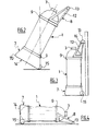
- la figure 1 représente schématiquement en coupe longitudinale partielle un mode de réalisation de la partie supérieure d'un réservoir de gaz selon l'invention ;
- les figures 2 - 4 représentent un mode de réalisation d'un réservoir selon l'invention en positions de roulage, d'accrochage et couché respectivement ; et
- la figure 5 est une vue analogue à la figure 1 de la partie inférieure d'un autre mode de réalisation d'une structure d'enveloppe de réservoir selon l'invention.
- Sur la figure 1 on reconnaît la partie supérieure d'une structure d'enveloppe 1 de stockage de gaz en forme de bouteille d'architecture composite, constituée, de façon connue en soi, d'une chemise intérieure ou « liner » 2 étanche ou de très faible perméabilité aux gaz à stocker, typiquement en métal, en particulier en acier inoxydable, ou en matériau plastique haute densité, se raccordant à une structure de raccord d'extrémité 3 faisant saillie vers l'extérieur et revêtue extérieurement d'au moins une couche de renforcement 4, typiquement en fibres de carbone imprégnées de résine époxyde.
- Selon un aspect de l'invention, cette couche de renforcement 4 est elle même revêtue d'une couche externe de protection 5, réalisée par exemple en fibres de verre et/ou aramide Rilsan™ (notamment type TWINTEX™ ou analogue), imprégnées de résine et formée localement, dans son épaisseur, au voisinage des extrémités opposées de l'enveloppe 1, typiquement au voisinage des extrémités de la partie de fût centrale cylindrique, avant son raccordement aux dômes d'extrémité avec plusieurs logements 6A, 6B angulairement répartis servant à recevoir un organe de fixation avec une structure de support ou de manutention du réservoir, typiquement, comme on le voit sur les figures 2-4, une jupe 7 de support et de transport et une structure de manutention et d'accrochage 8, chacune de ces structures comprenant une collerette d'extrémité 9 comprenant des organes de fixation adaptés pour coopérer avec ceux portés par la couche externe de protection 5. Cette dernière peut en outre contribuer à augmenter la tenue mécanique de la bouteille et/ou sa résistance à la pression des gaz.
- Dans le mode de réalisation représenté sur la figure 1, on a représenté un de ces organes de fixation sous la forme d'un insert fileté 10, dont la tête est noyée dans la couche externe 5 lors de la mise en place de cette dernière autour de la couche 4 et sur lequel on peut visser un écrou de maintien d'une collerette 9. On a également représenté sur cette figure 1 un autre organe de fixation sous la forme d'un bossage 11 formant un logement 6B en forme de queue d'aronde obtenu par bobinage sur un moule en trois parties démonté après durcissement du composite, par usinage, ou par insertion / collage du bossage 11, la queue d'aronde 6B étant destinée à coopérer avec un tenon correspondant d'un collier 9, introduit par rotation du collier vis à vis de l'enveloppe 1.
- Comme on le voit dans le mode de réalisation des figures 2 à 4, le collier de montage 9 de la structure de manutention 8 est avantageusement solidaire de deux triangles latéraux 12 dont les extrémités extérieures sont reliées par une poignée transversale 13. Le collier 9 de fixation de la structure de jupe 7 est quant à lui prolongé vers l'extérieur jusqu'au delà de l'extrémité hémisphérique de la structure d'enveloppe 1 (figure 4) par une partie en forme de tronc de pyramide présentant des arêtes d'extrémité telles que 70 empêchant le réservoir de rouler lorsqu'il est posé à plat dans une position autre que la position naturelle de pose à plat volontaire représenté sur la figure 4 et définissant à son extrémité libre une surface de pose 14 élargie et complétée, sur un de ses côtés, dans l'exemple représenté, par un rouleau 15 monté articulé dans les parois de la jupe 7. Selon un aspect de l'invention, les structures de jupe 7 et de manutention 8 sont montées sur la structure d'enveloppe 1 de façon que le rouleau 15 et la poignée 13 soient sensiblement parallèles, afin de permettre un déplacement aisé par glissement ou roulement, comme représenté sur la figure 2, et une pose à plat stable du réservoir, comme représenté sur la figure 4.
- De plus, comme représenté sur la figure 3, la poignée 13 s'étendant entre les triangles 12 permet l'accrochage du réservoir 1 sur un crochet mural 14 ou toute autre attache sur la paroi d'un véhicule de transport, par exemple une ambulance, la poignée pouvant être verrouillée par un cadenas sur ce crochet 16.
- Dans le mode de réalisation particulier représenté sur la figure 5, la couche de protection externe 5 est découplée de la couche de renforcement 4 par une couche intermédiaire 17 de mousse thermoplastique ou de feutre de fibres, par exemple de verre, présentant des capacités d'adsorption de choc pour améliorer encore la résistance au choc et aux vibrations du réservoir, s'étendant sur l'intégralité de la surface du réservoir ou, localement, sur des zones plus exposées, ou présentant des épaisseurs différentes selon les zones du réservoir.
- Le réservoir selon l'invention convient pour le stockage de tous gaz sous pression, plus particulièrement sous des pressions supérieures à 200 bars, notamment d'hydrogène pour l'alimentation de pile à combustible ou d'oxygène pour utilisations médicales, dans des dimensions comparables à celles des bouteilles classiques avec une hauteur typiquement comprise entre 0,50 et 1 mètre.
- Quoique l'invention ait été décrite en relation avec des modes de réalisation particuliers, elle ne s'en trouve pas limitée mais est susceptible de modifications et de variantes qui apparaîtront à l'homme du métier dans le cadre des revendications ci-après.
Claims (10)
- Réservoir de gaz sous pression, comprenant une structure d'enveloppe résistant à la pression (1) revêtue d'au moins une couche externe de protection (5) comprenant au moins un logement (6A, 6B) de réception d'un organe de fixation d'une structure de support (7) ou de manutention (8) du réservoir.
- Réservoir selon la revendication 1, comprenant une structure support (7) constituée d'une partie de jupe enveloppant au moins partiellement une extrémité de la structure d'enveloppe (1).
- Réservoir selon la revendication 2, caractérisé en ce que la partie de jupe comprend un moyen de déplacement à faible coefficient de friction (15).
- Réservoir selon la revendication 3, caractérisé en ce que le moyen de déplacement comprend un organe de roulement (15).
- Réservoir selon l'une des revendications 2 à 4, comprenant une structure de manutention (8) formant une poignée (13) de manutention ou d'accrochage montée sur l'extrémité opposée de la structure de réservoir (1).
- Réservoir selon la revendication 3 et la revendication 5, caractérisé en ce que la poignée (13) est sensiblement parallèle à l'axe de l'organe de roulement (15).
- Réservoir selon l'une des revendications précédentes, caractérisé en ce que la structure d'enveloppe est de type composite.
- Réservoir selon la revendication 7, caractérisé en ce que la structure d'enveloppe comporte un chemisage interne (2) revêtu d'au moins une couche fibreuse de renforcement (4).
- Réservoir selon la revendication 8, caractérisé en ce que la structure d'enveloppe comporte au moins localement une couche intermédiaire (17) en matériau adsorbant les chocs entre la couche externe de protection (5) et la couche de renforcement (4).
- Réservoir selon l'une des revendications précédentes, caractérisé en ce que la couche externe de protection (5) est composée de fibres de verre ou aramide.
Applications Claiming Priority (1)
| Application Number | Priority Date | Filing Date | Title |
|---|---|---|---|
| FR0550093A FR2880673B1 (fr) | 2005-01-11 | 2005-01-11 | Reservoir de gaz sous pression |
Publications (1)
| Publication Number | Publication Date |
|---|---|
| EP1679468A1 true EP1679468A1 (fr) | 2006-07-12 |
Family
ID=34953270
Family Applications (1)
| Application Number | Title | Priority Date | Filing Date |
|---|---|---|---|
| EP05300931A Withdrawn EP1679468A1 (fr) | 2005-01-11 | 2005-11-16 | Réservoir de gaz sous pression |
Country Status (2)
| Country | Link |
|---|---|
| EP (1) | EP1679468A1 (fr) |
| FR (1) | FR2880673B1 (fr) |
Cited By (6)
| Publication number | Priority date | Publication date | Assignee | Title |
|---|---|---|---|---|
| EP2048427A1 (fr) | 2007-10-12 | 2009-04-15 | Iveco Magirus Ag | Réservoir pour air comprimé |
| EP2048428A1 (fr) | 2007-10-12 | 2009-04-15 | Iveco Magirus Ag | Réservoir pour air comprimé |
| FR2923284A1 (fr) * | 2007-11-02 | 2009-05-08 | Metallurg Liotard Freres Sa So | Bouteille a gaz legere et anti-choc. |
| EP1970273A3 (fr) * | 2007-03-13 | 2010-11-24 | Alutech Gesellschaft m.b.H. | Système de fixation pour réservoir de véhicule |
| DE102015222392A1 (de) * | 2015-11-13 | 2017-05-18 | Bayerische Motoren Werke Aktiengesellschaft | Druckbehälter mit einem Lastring, Kraftfahrzeug und Verfahren zur Herstellung eines Druckbehälters |
| DE102017006085A1 (de) * | 2017-06-28 | 2019-01-03 | Audi Ag | Druckbehälter sowie Strukturbauteil mit darin verbautem Druckbehälter |
Citations (3)
| Publication number | Priority date | Publication date | Assignee | Title |
|---|---|---|---|---|
| US4918927A (en) * | 1989-09-06 | 1990-04-24 | Harsco Corporation | Cryogenic liquid container |
| EP0654633A1 (fr) * | 1993-11-22 | 1995-05-24 | SCHNEIDER INDUSTRIE S.I. Société Anonyme dite : | Réservoir, en particulier, bouteille à gaz |
| US6708990B1 (en) * | 2000-01-11 | 2004-03-23 | Robert Saino | Method and device for transporting a container having a threaded fitting |
-
2005
- 2005-01-11 FR FR0550093A patent/FR2880673B1/fr not_active Expired - Fee Related
- 2005-11-16 EP EP05300931A patent/EP1679468A1/fr not_active Withdrawn
Patent Citations (3)
| Publication number | Priority date | Publication date | Assignee | Title |
|---|---|---|---|---|
| US4918927A (en) * | 1989-09-06 | 1990-04-24 | Harsco Corporation | Cryogenic liquid container |
| EP0654633A1 (fr) * | 1993-11-22 | 1995-05-24 | SCHNEIDER INDUSTRIE S.I. Société Anonyme dite : | Réservoir, en particulier, bouteille à gaz |
| US6708990B1 (en) * | 2000-01-11 | 2004-03-23 | Robert Saino | Method and device for transporting a container having a threaded fitting |
Cited By (11)
| Publication number | Priority date | Publication date | Assignee | Title |
|---|---|---|---|---|
| EP1970273A3 (fr) * | 2007-03-13 | 2010-11-24 | Alutech Gesellschaft m.b.H. | Système de fixation pour réservoir de véhicule |
| EP2048427A1 (fr) | 2007-10-12 | 2009-04-15 | Iveco Magirus Ag | Réservoir pour air comprimé |
| EP2048428A1 (fr) | 2007-10-12 | 2009-04-15 | Iveco Magirus Ag | Réservoir pour air comprimé |
| CN101430042B (zh) * | 2007-10-12 | 2012-03-14 | 依维柯马基路斯公司 | 压缩气体贮罐 |
| CN101430041B (zh) * | 2007-10-12 | 2012-08-29 | 依维柯马基路斯公司 | 压缩气体贮罐 |
| AU2008229830B2 (en) * | 2007-10-12 | 2014-08-14 | Iveco Magirus Ag | Compressed air reservoir |
| AU2008229822B2 (en) * | 2007-10-12 | 2014-12-11 | Iveco Magirus Ag | Compressed air reservoir |
| FR2923284A1 (fr) * | 2007-11-02 | 2009-05-08 | Metallurg Liotard Freres Sa So | Bouteille a gaz legere et anti-choc. |
| DE102015222392A1 (de) * | 2015-11-13 | 2017-05-18 | Bayerische Motoren Werke Aktiengesellschaft | Druckbehälter mit einem Lastring, Kraftfahrzeug und Verfahren zur Herstellung eines Druckbehälters |
| DE102017006085A1 (de) * | 2017-06-28 | 2019-01-03 | Audi Ag | Druckbehälter sowie Strukturbauteil mit darin verbautem Druckbehälter |
| DE102017006085B4 (de) | 2017-06-28 | 2021-08-19 | Audi Ag | Druckbehälter sowie Druckbehälteranordnung |
Also Published As
| Publication number | Publication date |
|---|---|
| FR2880673A1 (fr) | 2006-07-14 |
| FR2880673B1 (fr) | 2007-04-27 |
Similar Documents
| Publication | Publication Date | Title |
|---|---|---|
| EP2739895B1 (fr) | Cuve etanche et thermiquement isolante | |
| FR2706578A1 (fr) | Réservoir de stockage d'hydrocarbures sous pression. | |
| FR2673256A1 (fr) | Reservoir sous pression pour stocker un fluide sous pression. | |
| WO2019012236A1 (fr) | Cuve etanche et thermiquement isolante | |
| EP3361138A1 (fr) | Structure de dome gaz pour une cuve etanche et thermiquement isolante | |
| EP1192389B1 (fr) | Dispositif de protection d'un recipient et recipient equipe de ce dispositif | |
| EP3004718A2 (fr) | Caisse autoporteuse pour l'isolation thermique d'une cuve de stockage d'un fluide et procede de fabrication d'une telle caisse | |
| FR3099539A1 (fr) | Dispositif d’évacuation de gaz comprimé | |
| FR3084438A1 (fr) | Cuve etanche et thermiquement isolante | |
| EP3055606B1 (fr) | Caisse autoporteuse pour l'isolation thermique d'une cuve de stockage d'un fluide et procede de fabrication d'une telle caisse | |
| WO2019012237A1 (fr) | Cuve etanche et thermiquement isolante a bande de support incurvee | |
| EP3004719B1 (fr) | Procede de fabrication d'une caisse autoporteuse pour l'isolation thermique d'une cuve de stockage d'un fluide et caisse autoporteuse ainsi realisee | |
| WO2020016509A1 (fr) | Installation de stockage de fluide | |
| WO2023066613A1 (fr) | Cuve étanche et isolante pour le stockage et/ou le transport d'un gaz liquéfié | |
| FR2880673A1 (fr) | Reservoir de gaz sous pression | |
| EP1067300B1 (fr) | Réservoir en matériau composite destiné au stockage de gaz liquéfié sous pression | |
| EP4357661A1 (fr) | Tour de chargement et/ou de déchargement destinée à équiper une cuve de stockage en gaz liquéfié | |
| WO2021144531A1 (fr) | Double trappe d'accès pour une cuve de transport de gaz liquéfié | |
| WO2021254999A1 (fr) | Dôme liquide d'une cuve de stockage pour gaz liquéfié | |
| FR3008163A1 (fr) | Element calorifuge convenant pour la realisation d'une barriere isolante dans une cuve etanche et isolante | |
| WO2023089156A1 (fr) | Cuve étanche et thermiquement isolante | |
| EP0518272B1 (fr) | Réservoir et son procédé de fabrication | |
| FR3030679A1 (fr) | Reservoir pour gaz sous pression a liner ultra mince | |
| FR2585446A1 (fr) | Reservoir de fluide sous pression, notamment reservoir de gaz de petrole liquefie pour vehicule automobile | |
| EP4170222B1 (fr) | Réservoir cryogénique de stockage de gaz liquéfié |
Legal Events
| Date | Code | Title | Description |
|---|---|---|---|
| PUAI | Public reference made under article 153(3) epc to a published international application that has entered the european phase |
Free format text: ORIGINAL CODE: 0009012 |
|
| AK | Designated contracting states |
Kind code of ref document: A1 Designated state(s): AT BE BG CH CY CZ DE DK EE ES FI FR GB GR HU IE IS IT LI LT LU LV MC NL PL PT RO SE SI SK TR |
|
| AX | Request for extension of the european patent |
Extension state: AL BA HR MK YU |
|
| 17P | Request for examination filed |
Effective date: 20070112 |
|
| 17Q | First examination report despatched |
Effective date: 20070216 |
|
| AKX | Designation fees paid |
Designated state(s): AT BE BG CH CY CZ DE DK EE ES FI FR GB GR HU IE IS IT LI LT LU LV MC NL PL PT RO SE SI SK TR |
|
| RAP1 | Party data changed (applicant data changed or rights of an application transferred) |
Owner name: L'AIR LIQUIDE, SOCIETE ANONYME POUR L'ETUDE ET L'E |
|
| RAP1 | Party data changed (applicant data changed or rights of an application transferred) |
Owner name: L'AIR LIQUIDE, SOCIETE ANONYME POUR L'ETUDE ET L'E |
|
| GRAP | Despatch of communication of intention to grant a patent |
Free format text: ORIGINAL CODE: EPIDOSNIGR1 |
|
| INTG | Intention to grant announced |
Effective date: 20160926 |
|
| STAA | Information on the status of an ep patent application or granted ep patent |
Free format text: STATUS: THE APPLICATION IS DEEMED TO BE WITHDRAWN |
|
| 18D | Application deemed to be withdrawn |
Effective date: 20170207 |