EP1676799A1 - Gerät zum Führen von Bögen - Google Patents
Gerät zum Führen von Bögen Download PDFInfo
- Publication number
- EP1676799A1 EP1676799A1 EP05027649A EP05027649A EP1676799A1 EP 1676799 A1 EP1676799 A1 EP 1676799A1 EP 05027649 A EP05027649 A EP 05027649A EP 05027649 A EP05027649 A EP 05027649A EP 1676799 A1 EP1676799 A1 EP 1676799A1
- Authority
- EP
- European Patent Office
- Prior art keywords
- sheet
- convey
- guide member
- movable guide
- movable
- Prior art date
- Legal status (The legal status is an assumption and is not a legal conclusion. Google has not performed a legal analysis and makes no representation as to the accuracy of the status listed.)
- Withdrawn
Links
- 238000011144 upstream manufacturing Methods 0.000 claims description 17
- 230000000694 effects Effects 0.000 description 4
- 230000001105 regulatory effect Effects 0.000 description 3
- 239000011248 coating agent Substances 0.000 description 2
- 238000000576 coating method Methods 0.000 description 2
- 239000003086 colorant Substances 0.000 description 1
- 230000007423 decrease Effects 0.000 description 1
- 238000002360 preparation method Methods 0.000 description 1
- 230000037303 wrinkles Effects 0.000 description 1
Images
Classifications
-
- B—PERFORMING OPERATIONS; TRANSPORTING
- B65—CONVEYING; PACKING; STORING; HANDLING THIN OR FILAMENTARY MATERIAL
- B65H—HANDLING THIN OR FILAMENTARY MATERIAL, e.g. SHEETS, WEBS, CABLES
- B65H29/00—Delivering or advancing articles from machines; Advancing articles to or into piles
- B65H29/02—Delivering or advancing articles from machines; Advancing articles to or into piles by mechanical grippers engaging the leading edge only of the articles
- B65H29/04—Delivering or advancing articles from machines; Advancing articles to or into piles by mechanical grippers engaging the leading edge only of the articles the grippers being carried by endless chains or bands
- B65H29/041—Delivering or advancing articles from machines; Advancing articles to or into piles by mechanical grippers engaging the leading edge only of the articles the grippers being carried by endless chains or bands and introducing into a pile
-
- B—PERFORMING OPERATIONS; TRANSPORTING
- B65—CONVEYING; PACKING; STORING; HANDLING THIN OR FILAMENTARY MATERIAL
- B65H—HANDLING THIN OR FILAMENTARY MATERIAL, e.g. SHEETS, WEBS, CABLES
- B65H29/00—Delivering or advancing articles from machines; Advancing articles to or into piles
- B65H29/02—Delivering or advancing articles from machines; Advancing articles to or into piles by mechanical grippers engaging the leading edge only of the articles
- B65H29/04—Delivering or advancing articles from machines; Advancing articles to or into piles by mechanical grippers engaging the leading edge only of the articles the grippers being carried by endless chains or bands
-
- B—PERFORMING OPERATIONS; TRANSPORTING
- B65—CONVEYING; PACKING; STORING; HANDLING THIN OR FILAMENTARY MATERIAL
- B65H—HANDLING THIN OR FILAMENTARY MATERIAL, e.g. SHEETS, WEBS, CABLES
- B65H29/00—Delivering or advancing articles from machines; Advancing articles to or into piles
- B65H29/54—Article strippers, e.g. for stripping from advancing elements
- B65H29/56—Article strippers, e.g. for stripping from advancing elements for stripping from elements or machines
-
- B—PERFORMING OPERATIONS; TRANSPORTING
- B65—CONVEYING; PACKING; STORING; HANDLING THIN OR FILAMENTARY MATERIAL
- B65H—HANDLING THIN OR FILAMENTARY MATERIAL, e.g. SHEETS, WEBS, CABLES
- B65H5/00—Feeding articles separated from piles; Feeding articles to machines
- B65H5/08—Feeding articles separated from piles; Feeding articles to machines by grippers, e.g. suction grippers
- B65H5/12—Revolving grippers, e.g. mounted on arms, frames or cylinders
-
- B—PERFORMING OPERATIONS; TRANSPORTING
- B65—CONVEYING; PACKING; STORING; HANDLING THIN OR FILAMENTARY MATERIAL
- B65H—HANDLING THIN OR FILAMENTARY MATERIAL, e.g. SHEETS, WEBS, CABLES
- B65H5/00—Feeding articles separated from piles; Feeding articles to machines
- B65H5/36—Article guides or smoothers, e.g. movable in operation
Definitions
- the present invention relates to a sheet guide apparatus which is connected to a printing press for printing a sheet, a coating machine for coating the sheet, or the like, and conveys the sheet in a stable state.
- a sheet guide member is arranged around a delivery cylinder to prevent rubbing or wrinkles which cause a printing trouble during sheet conveyance.
- the sheet guide member blows air in a direction perpendicular to the sheet convey direction.
- problems occur when a so-called thick sheet having a relatively large thickness is to be conveyed around the delivery cylinder. More specifically, because the thick sheet does not flex readily and is heavy, a large centrifugal force is generated to bring the printing surface on the reverse side of the trailing edge of the sheet into contact with the sheet guide member to damage or rub the printing surface.
- a sheet guide apparatus comprising a transport cylinder which holds and conveys a sheet, convey means for holding the sheet received from the transport cylinder and conveying the sheet along a first convey path which is at least substantially arcuate, and a sheet guide structure which guides the sheet conveyed by the convey means, the sheet guide structure comprising movable guide means which is movable between positions close to and spaced apart from the first convey path and stationary guide means which is stationarily arranged at a position spaced apart from the first convey path, wherein when the movable guide means is close to the first convey path, a first guide surface having a continuous substantially arcuate section is formed by only the movable guide means, and when the movable guide means is spaced apart from the first convey path, a second guide surface having a continuous substantially arcuate section is formed by the movable guide means and the stationary guide means.
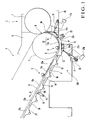
- a sheet guide apparatus according to the first embodiment of the present invention will be described with reference to Figs. 1 to 3.
- a printing unit 2 of a sheet-fed perfector comprises a plurality of printing units (not shown) corresponding to different colors.
- a transfer cylinder 1 serving as a transport cylinder is arranged at the final end of a cylinder group that forms the final printing unit.
- a delivery cylinder 3 which forms an arcuate convey path is arranged to oppose the transfer cylinder 1.
- a pair of delivery chains 5 (one delivery chain is not shown) serving as a convey means are looped around a sprocket (not shown) coaxial with the delivery cylinder 3 and a sprocket (not shown) at the rear end of a delivery unit 4 of the sheet-fed perfector.
- a plurality of gripper bars (not shown) are supported between the pair of delivery chains 5 at a constant interval in a traveling direction A of the delivery chains 5.
- a plurality of delivery grippers 6 each comprising a gripper and gripper pad line up on each gripper bar at a constant interval in the longitudinal direction of the gripper bar (widthwise direction of the sheet).
- a first movable guide member 7 extends downstream of the delivery cylinder 3 in the sheet convey direction from near the downstream side of a point B where the transfer cylinder 1 and delivery cylinder 3 oppose.
- the first movable guide member 7 has a guide surface 7a with an arcuate section having substantially the same curvature as that of the outer surface of the opposing delivery cylinder 3.
- the first movable guide member 7 is supported by guide rails 9 attached to delivery frames 8 to be movable between positions close to and spaced apart from the delivery cylinder 3 (arcuate convey path).
- the distal end of a rod 11a of a first air cylinder 11 having a pivotally mounted cylinder end is pivotally mounted on frames 10 of the printing unit 2.
- the air cylinder 11 is driven by a solenoid valve unit 11b which switches between supply and discharge of pressurized air.
- a second movable guide member 12 extends downstream of the first movable guide member 7 in the sheet convey direction to be adjacent to it.
- the second movable guide member 12 has a guide surface 12a with an arcuate section having substantially the same curvature as that of the outer surface of the opposing delivery cylinder 3.
- Linear guide members 13, 14, and 15 are sequentially arranged downstream of the second movable guide member 12 in the sheet convey direction to be adjacent to it.
- the linear guide members 13, 14, and 15 are connected to each other by a movable lever 16 fixed to their lower surfaces.
- the second movable guide member 12 is supported by one end 16a of the movable lever 16 which is upstream in the sheet convey direction through a support plate 17.
- the first and second movable guide members 7 and 12 and linear guide members 13, 14, and 15 form a movable guide means.
- the second movable guide member 12 and linear guide members 13, 14, and 15 may be integral.
- the distal end of a rod 21a of a second air cylinder 21 is pivotally mounted on the end 16a of the movable lever 16.
- a downstream end 16b of the movable lever 16 in the sheet convey direction is swingably attached to the delivery frames 8 by a pivot shaft 19 through a swing lever 18.
- the cylinder end of the air cylinder 21 is attached to the delivery frames 8 through a bracket 20.
- the air cylinder 21 is driven by a solenoid valve unit 21b which switches between supply and discharge of the pressurized air.
- the second movable guide member 12 is adjacent to the first movable guide member 7 which is close to the delivery cylinder 3, and the guide surfaces 7a and 12a form a thin-sheet guide surface 22 having a continuous substantially arcuate section.
- the thin-sheet guide surface 22 opposes the outer surface of the delivery cylinder 3 to be close to it between a position near the opposing point B of the transfer cylinder 1 and delivery cylinder 3 and a point C where the delivery chains 5 start to separate from the sprocket.
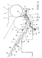
- the movable lever 16 pivots in a direction (clockwise in Fig. 1) to separate from the delivery cylinder 3 about the pivot shaft 19 as the center. Then, the guide surfaces 13a, 14a, and 15a of the linear guide members 13, 14, and 15 separate from the delivery chains 5 (linear convey path) to be gradually farther from them, as shown in Fig. 2, and the guide surface 12a of the second movable guide member 12 opposes the outer surface of the delivery cylinder 3 to be spaced apart from it.
- a stationary guide member 23 having a stationary guide surface 23a with an arcuate section having substantially the same curvature as that of the outer surface of the opposing delivery cylinder 3 is attached through a bracket (not shown).
- the stationary guide surface 23a may alternatively be a flat surface.
- the stationary guide member 23 is located between the first and second movable guide members 7 and 12.
- the stationary guide surface 23a together with the guide surfaces 7a and 12a of the first and second movable guide members 7 and 12 forms a thick-sheet guide surface 24 having a continuous substantially arcuate section.
- the thick-sheet guide surface 24 opposes the outer surface of the delivery cylinder 3 to be spaced apart from it.
- Linear guide members 26 and 27 are sequentially attached to the delivery frames 8 further downstream of the linear guide member 15 in the sheet convey direction to be adjacent to it.
- the linear guide members 26 and 27 oppose the pair of delivery chains 5 to be close to them and have flat guide surfaces 26a and 27a, respectively.
- the movable guide members 7 and 12 to 15, stationary guide member 23, and linear guide members 26 and 27 form a sheet guide structure 101.
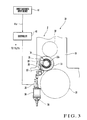
- the switching control is interlocked with control of adjusting the gap between the impression cylinder and blanket cylinder.
- a cylinder throw on/off mechanism 30 shown in Fig. 3 an impression cylinder 31 and plate cylinder 32 which form the printing unit 2 of the sheet-fed perfector are rotatably supported at a predetermined gap by the pair of frames 10.
- a blanket cylinder 33 is arranged between the two cylinders 31 and 32.
- Two end shafts 33a of the blanket cylinder 33 are supported by the pair of frames 10 through a pair of eccentric bearings 34 each having inner and outer races with eccentric shaft cores.
- a bearing lever 35 is fixed to the outer race of each eccentric bearing 34.
- the bearing lever 35 is connected to a driving rod 39 of a stepping motor 38 which is supported by the frames 10 through a connection lever 36 and 37 to extend vertically.
- a controller 40 performs drive control of the stepping motor 38 based on an input sheet thickness signal 41a.
- the controller 40 When the controller 40 receives the sheet thickness signal 41a from a sheet thickness input device 41, the controller 40 calculates the gap between the blanket cylinder 33 and impression cylinder 31 corresponding to the sheet thickness, i.e., the stop position of the driving rod 39, and determines the rotational speed of the stepping motor 38. At this time, the controller 40 compares the sheet thickness indicated by the sheet thickness signal 41a with a preset threshold (e.g., 0.2 mm). If the sheet thickness signal 41a is larger than the threshold, the controller 40 determines that the sheet is a thick sheet. If the sheet thickness signal 41a is smaller than the threshold, the controller 40 determines that the sheet is a thin sheet.
- a preset threshold e.g., 0.2 mm
- the controller 40 controls the solenoid valve units 11b and 21b to move the rods 11a and 21a of the air cylinders 11 and 21 backward.
- the controller 40 controls the solenoid valve units 11b and 21b to move the rods 11a and 21a of the air cylinders 11 and 21 forward.
- Sheet guide operation in the sheet guide apparatus having the above arrangement will be described.
- a sheet thickness signal 41a indicating a thin sheet is input to the controller 40.
- the controller 40 determines the rotational speed of the stepping motor 38 in accordance with the input sheet thickness signal 41a, to move the driving rod 39 forward or backward into and from the gap between the blanket cylinder 33 and impression cylinder 31 corresponding to the sheet thickness.
- the controller 40 checks whether the sheet P is a thick sheet or thin sheet based on the input sheet thickness signal 41a.
- the controller 40 controls the solenoid valve units 11b and 21b to move the rods 11a and 21a of the air cylinders 11 and 21 forward.
- the guide surfaces 7a and 12a of the first and second movable guide members 7 and 12 oppose the outer surface of the delivery cylinder 3 to be close to it, as shown in Fig. 1.
- the guide surface 14a of the linear guide member 14 opposes the delivery chains 5 to be close to them.
- the first and second movable guide members 7 and 12 are adjacent to each other, and the two guide surfaces 7a and 12a form the thin-sheet guide surface 22 having a continuous substantially arcuate section.
- the thin-sheet guide surface 22 opposes the outer surface of the delivery cylinder 3 to be close to it between the position near the opposing point B of the transfer cylinder 1 and delivery cylinder 3 and the point C where the sprocket and delivery chains 5 start to separate.
- the first and second movable guide members 7 and 12 and linear guide members 13, 14, and 15 blow air from their nozzle holes (not shown) in a direction (widthwise direction of the sheet P) perpendicular to the convey direction A of the sheet P.
- the sheet (thin sheet) P passes between the impression cylinders 31 and blanket cylinders 33 of the plurality of printing units of the printing unit 2 to be subjected to double-sided printing.
- the sheet P is conveyed as it is gripped by the grippers of the transfer cylinder 1 located at the final end of the printing unit 2, and gripping-changed to the delivery grippers 6 at the opposing point B of the delivery cylinder 3.
- the thin sheet P which is gripping-changed to the delivery grippers 6 is conveyed around the delivery cylinder 3, i.e., along the substantially arcuate convey path since the opposing point B of the transfer cylinder 1 and delivery cylinder 3 until the point C where the sprocket and the delivery chains 5 start to separate.
- the thin-sheet guide surface 22 having the continuous arcuate section opposes the outer surface of the delivery cylinder 3 to be close to it.
- the instability of the sheet P is regulated by the Venturi effect of the air blown from the nozzle holes of the first and second movable guide members 7 and 12, so that the sheet P is conveyed stably without coming into contact with the thin-sheet guide surface 22.
- the guide surfaces 13a, 14a, and 15a of the linear guide members 13, 14, and 15 oppose the delivery chains 5 to be close to them.
- the sheet P is linearly conveyed as it is guided by the guide surfaces 13a, 14a, and 15a.
- a sheet thickness signal 41a indicating the sheet thickness is input to the controller 40.
- the controller 40 determines the rotational speed of the stepping motor 38 in accordance with the input sheet thickness signal 41a, to move the driving rod 39 forward or backward into or from the gap between the blanket cylinder 33 and impression cylinder 31 corresponding to the sheet thickness.
- the controller 40 determines that the sheet P is a thick sheet based on the input sheet thickness signal 41a, and controls the solenoid valve units 11b and 21b to move the rods 11a and 21a of the air cylinders 11 and 21 backward.
- the guide surfaces 7a and 12a of the first and second movable guide members 7 and 12 oppose the outer surface of the delivery cylinder 3 to be spaced apart from it, as shown in Fig. 2.
- the stationary guide member 23 is located between the first and second movable guide members 7 and 12.
- the guide surfaces 7a and 12a together with the stationary guide surface 23a form the thick-sheet guide surface 24 having a continuous substantially arcuate section.
- the thick-sheet guide surface 24 opposes the outer surface of the delivery cylinder 3 to be spaced apart from it substantially throughout the entire sheet convey direction from upstream to downstream. As the first movable guide member 7 moves, the upstream end 7b of the first movable guide member 7 in the sheet convey direction moves close to the transfer cylinder 1.
- the guide surfaces 13a, 14a, and 15a of the linear guide members 13, 14, and 15 separate from the delivery chains 5 to be gradually farther from them downstream in the sheet convey direction. More specifically, the guide surfaces 13a, 14a, and 15a, while being continuous from the guide surface 12a of the second movable guide member 12, gradually move close to the delivery chains 5 downward in the sheet convey direction, and then become continuous to the guide surface 26a of the linear guide member 26. Thus, the guide surfaces 12a, 13a, 14a, 15a, and 26a form a non-step convey path.
- the sheet (thick sheet) P passes between the impression cylinders 31 and blanket cylinders 33 of the plurality of printing units of the printing unit 2 to be subjected to double-sided printing.
- the sheet P is conveyed as it is gripped by the grippers of the transfer cylinder 1 located at the final end of the printing unit 2, and gripping-changed to the delivery grippers 6 at the opposing point B of the delivery cylinder 3.
- the thin sheet P which is gripping-changed to the delivery grippers 6 is to be conveyed around the delivery cylinder 3, its trailing edge is largely separated from the delivery cylinder 3 by the centrifugal force.
- the thick-sheet guide surface 24 opposes the delivery cylinder 3 to be spaced apart from it substantially throughout the entire sheet convey direction from upstream to downstream, the trailing edge of the sheet P will not come into contact with the thick-sheet guide surface 24. Also, as the end 7b of the first movable guide member 7 moves close to the transfer cylinder 1, the trailing edge of the sheet P will not collide against the end 7b or enter between the transfer cylinder 1 and end 7b.
- the stationary guide surface 23a together with the guide surfaces 7a and 12a forms the thick-sheet guide surface 24 which is continuous and opposes the outer surface of the delivery cylinder 3 to be spaced apart from it, the sheet P which is being conveyed around the delivery cylinder 3 will not come into contact with the thick-sheet guide surface 24. Thus, the sheet P is conveyed in a stable state, and its printing surface will not be damaged or rubbed.
- the trailing edge of the sheet P is spaced apart from the outer surface of the delivery cylinder 3 by the remaining centrifugal force.
- the guide surface 13a of the linear guide member 13 is also spaced apart from the outer surface of the delivery cylinder 3 and the delivery chains 5.
- the sheet P does not come into contact with the guide surface 13a.
- the sheet P on which the centrifugal force no longer acts is guided along the convey path by the linear guide members 14, 15, 26, and 27 to be substantially in contact with the delivery chains 5.
- the downstream end of the guide surface 15a in the sheet convey direction and the upstream end of the guide surface 26a in the sheet convey direction are close to each other to form no step between them.
- the conveyed sheet P does not collide against the upstream end of the guide surface 26a in the sheet convey direction. Therefore, damages or rubbing to the printing surface of the sheet P can be prevented, and the instability of the sheet can be prevented, so the sheet P can be conveyed smoothly.
- an inverted-J-shaped movable guide member 50 integrally comprises a curved portion 51 and linear portion 52.
- the curved portion 51 has a guide surface 51a with an arcuate section having substantially the same curvature as that of the outer surface of an opposing delivery cylinder 3.
- the linear portion 52 is continuous to the curved portion 51 and has a linear guide surface 52a.
- the movable guide member 50 is swingably supported by a pivot shaft 53 which is connected to the downstream end of the linear portion 52 in the sheet convey direction and supported by delivery frames.
- An air cylinder 55 having a rod 55a is pivotally mounted on the delivery frames, and the rod 55a is connected to the center of the curved portion 51 of the movable guide member 50.
- Supply and discharge of pressurized air of the air cylinder 55 are controlled by a solenoid valve unit 55b.
- the guide surface 51a of the curved portion 51 of the movable guide member 50 opposes the outer surface of the delivery cylinder 3 to be close to it.
- the guide surface 52a of the linear portion 52 opposes delivery chains 5 to be close to them, and an upstream end 51b of the curved portion 51 in the sheet convey direction moves close to a transfer cylinder 1.
- a stationary guide member 56 having a guide surface 56a is attached to the delivery frames, and the guide surface 56a opposes the outer surface of the delivery cylinder 3 to be spaced apart from it. In this case, only the guide surface 51a of the curved portion 51 of the movable guide member 50 forms a thin-sheet guide surface.
- An upstream end 56b of the stationary guide member 56 in the sheet convey direction is arranged close to the transfer cylinder 1.
- the movable guide member 50 and stationary guide member 56 form a sheet guide structure 102.
- the thick-sheet guide surface 57 is formed by one movable guide member 50 and one stationary guide member 56.
- the stationary guide member 56 is positioned closer to the transfer cylinder 1 than the movable guide member 50.
- the guide surface 52a of the linear portion 52 which forms the movable guide member 50 opposes the outer surface of the delivery cylinder 3 to be spaced apart from it, and the guide surface 52a of the linear portion 52 separates from the delivery chains 5 to be gradually farther from them toward the delivery cylinder 3.
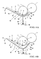
- a controller 40 Prior to printing operation, when the thickness of a sheet P is input to a sheet thickness input device 41 prior to printing, a controller 40 checks whether the sheet P is a thick sheet or thin sheet. When the sheet P is determined to be a thin sheet, the controller 40 controls the solenoid valve unit 55b of the air cylinder 55 to move the rod 55a the air cylinder 55 forward. Thus, the guide surface 51a of the curved portion 51 of the movable guide member 50 opposes the outer surface of the delivery cylinder 3 to be close to it, as shown in Fig. 4A.
- the end 51b of the curved portion 51 moves close to the transfer cylinder 1, and the guide surface 52a of the linear portion 52 opposes the delivery chains 5 to be close to them.
- the curved portion 51 and linear portion 52 blow air from their nozzle holes (not shown) in a direction (widthwise direction of the sheet) perpendicular to a traveling direction A of the sheet P.
- the sheet (thin sheet) P which has been printed on its two surfaces and conveyed is gripping-changed from the grippers of the transfer cylinder 1 to delivery grippers 6 at an opposing point B of the delivery cylinder 3.
- the guide surface 51a of the curved portion 51 opposes the outer surface of the delivery cylinder 3 to be close to it.
- the instability of the thin sheet P is regulated by the Venturi effect of the air blown from the nozzle holes of the curved portion 51, so that the sheet P is conveyed stably without coming into contact with the guide surface 51a.
- the guide surface 52a of the linear portion 52 opposes the delivery chains 5 to be close to them.
- the sheet P is linearly guided as it is guided by the guide surface 52a.
- the thick-sheet guide surface 57 has substantially the same curvature as that of the delivery cylinder 3, and opposes the outer surface of the delivery cylinder 3 to be spaced apart from it. Simultaneously, the guide surface 52a of the linear portion 52 which forms the movable guide member 50 separates from the delivery chains 5 to be gradually farther from them toward the delivery cylinder 3.
- the sheet (thick sheet) P which has been printed on its two surfaces and conveyed is gripping-changed from the grippers of the transfer cylinder 1 to the delivery grippers 6 at the opposing point B of the delivery cylinder 3.
- the sheet P which is gripping-changed to the delivery grippers 6 is to be conveyed around the delivery cylinder 3, its trailing edge is largely separated from the delivery cylinder 3 by the centrifugal force.
- the thick-sheet guide surface 57 has substantially the same curvature as that of the delivery cylinder 3 and opposes the outer surface of the delivery cylinder 3 to be spaced apart from it, the sheet P is conveyed stably without coming into contact with the thick-sheet guide surface 57.
- the trailing edge of the sheet P will not collide against the end 56b or enter between the transfer cylinder 1 and the right end 56b.
- the printing surface of the thick sheet P can be prevented from being damaged or rubbed.
- the trailing edge of the sheet P is still kept away from the delivery cylinder 3 by the remaining centrifugal force.
- the guide surface 52a of the linear portion 52 is spaced apart from the delivery chains 5 to be gradually farther from them toward the delivery cylinder 3, the thick sheet P can be prevented from coming into contact with the guide surface 52a.
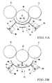
- a transfer cylinder 60 is arranged between two impression cylinders 61 and 62 to serve as a convey means which opposes each of the impression cylinders 61 and 62.
- First and second movable guide members 63 and 64 respectively having first and second guide surfaces 63a and 64a each with the same curvature as that of the outer surface of the transfer cylinder 60 are arranged to oppose the outer surface of the transfer cylinder 60.
- the cylinder ends of air cylinders 65 and 66 respectively having rods 65a and 66a are pivotally mounted on printing press frames, and the distal ends of the rods 65a and 66a of the air cylinders 65 and 66 are respectively pivotally mounted on the first and second movable guide members 63 and 64.
- Supply and discharge of pressurized air of the air cylinders 65 and 66 are controlled by solenoid valve units 65b and 66b.
- the first and second movable guide members 63 and 64 move close to the outer surface of the transfer cylinder 60. Simultaneously, the first and second movable guide members 63 and 64 move close to each other.
- the guide surface 63a of the first movable guide member 63 and the guide surface 64a of the second movable guide member 64 form a thin-sheet guide surface 68 having a continuous substantially arcuate section.
- the thin-sheet guide surface 68 opposes the outer surface of the transfer cylinder 60 to be close to it and has substantially the same curvature as that of the outer surface of the transfer cylinder 60. While the first and second movable guide members 63 and 64 are close to the outer surface of the transfer cylinder 60, an upstream end 63b of the first movable guide member 63 in the sheet convey direction moves close to the impression cylinder 61.
- a stationary guide member 67 having a guide surface 67a with substantially the same curvature as that of the outer surface of the transfer cylinder 60 is fixed to the printing press frames.
- the stationary guide member 67 is located between the first and second movable guide members 63 and 64.
- the guide surface 67a of the stationary guide member 67 together with the guide surfaces 63a and 64a of the first and second movable guide members 63 and 64 forms a thick-sheet guide surface 69 having a continuous substantially arcuate section.
- the thick-sheet guide surface 69 has the same curvature as that of the outer surface of the transfer cylinder 60, and opposes the outer surface of the transfer cylinder 60 to be spaced apart from it.
- the end 63b of the first movable guide member 63 moves close to the impression cylinder 61.
- the first and second movable guide members 63 and 64 and the stationary guide member 67 form a sheet guide structure 103.
- the solenoid valve units 65b and 66b are controlled to move the rods 65a and 66a of the air cylinders 65 and 66 forward, as shown in Fig. 5A.
- the first and second movable guide members 63 and 64 move close to the outer surface of the transfer cylinder 60 to form the thin-sheet guide surface 68.
- the thin-sheet guide surface 68 has substantially the same curvature as that of the outer surface of the transfer cylinder 60, and opposes the outer surface of the transfer cylinder 60 to be close to it.
- the end 63b of the first movable guide member 63 moves close to the impression cylinder 61.
- the instability of the thin sheet which is gripping-changed from the grippers of the impression cylinder 61 to the grippers of the transfer cylinder 60 and to be conveyed along the substantially arcuate convey path around the impression cylinder 61, is regulated by the Venturi effect of the air blown from the nozzle holes of the first and second movable guide members 63 and 64, so that the thin plate is conveyed stably without coming into contact with the thin-sheet guide surface 68.
- the solenoid valve units 65b and 66b are controlled to move the rods 65a and 66a of the air cylinders 65 and 66 backward, as shown in Fig. 5B.
- the first and second movable guide members 63 and 64 separate from the outer surface of the transfer cylinder 60 to form the thick-sheet guide surface 69.
- the thick-sheet guide surface 69 has substantially the same curvature as that of the outer surface of the transfer cylinder 60, and opposes the outer surface of the transfer cylinder 60 to be spaced apart from it. Simultaneously, the end 63b of the first movable guide member 63 moves close to the impression cylinder 61.
- the thick sheet which is gripping-changed from the grippers of the impression cylinder 61 to the grippers of the transfer cylinder 60 is to be conveyed around the transfer cylinder 60, its trailing edge is largely separated from the outer surface of the transfer cylinder 60 by the centrifugal force.
- the thick-sheet guide surface 69 has substantially the same curvature as that of the outer surface of the transfer cylinder 60, and opposes the outer surface of the transfer cylinder 60 to be spaced apart from it. Therefore, the thick sheet is conveyed stably without coming into contact with the thick-sheet guide surface 69.
- the end 63b of the first movable guide member 63 is close to the impression cylinder 61.
- the trailing edge of the sheet does not collide against the end 63b or enter between the impression cylinder 61 and end 63b.
- the printing surface of the thick plate can accordingly be prevented from being damaged or rubbed.
- the stationary guide surfaces 23a, 56a, and 67a of the stationary guide members 23, 56, and 67 need not always be arcuate surfaces but can be flat surfaces.
- the printing target is a sheet
- the printing target can be a film-type sheet.
- the printing surface can be prevented from being damaged or rubbed.
- the printing surface on the reverse side of the sheet can be prevented from being damaged or rubbed.
Applications Claiming Priority (1)
| Application Number | Priority Date | Filing Date | Title |
|---|---|---|---|
| JP2004368999A JP4369357B2 (ja) | 2004-12-21 | 2004-12-21 | シート状物案内装置 |
Publications (1)
| Publication Number | Publication Date |
|---|---|
| EP1676799A1 true EP1676799A1 (de) | 2006-07-05 |
Family
ID=35502505
Family Applications (1)
| Application Number | Title | Priority Date | Filing Date |
|---|---|---|---|
| EP05027649A Withdrawn EP1676799A1 (de) | 2004-12-21 | 2005-12-16 | Gerät zum Führen von Bögen |
Country Status (4)
| Country | Link |
|---|---|
| US (1) | US7497437B2 (de) |
| EP (1) | EP1676799A1 (de) |
| JP (1) | JP4369357B2 (de) |
| CN (1) | CN100567110C (de) |
Families Citing this family (8)
| Publication number | Priority date | Publication date | Assignee | Title |
|---|---|---|---|---|
| DE102005024992B4 (de) * | 2005-06-01 | 2007-02-08 | Heidelberger Druckmaschinen Ag | Verfahren und Vorrichtung zum Fördern eines Bogens durch eine drucktechnische Maschine |
| US7594657B2 (en) * | 2007-01-31 | 2009-09-29 | Hewlett-Packard Development Company, L.P. | Medium pressing guide |
| JP5433261B2 (ja) * | 2009-03-11 | 2014-03-05 | 株式会社小森コーポレーション | シート状物案内装置 |
| CN102700243B (zh) * | 2011-03-28 | 2016-04-06 | 海德堡印刷机械股份公司 | 用于输送页张的装置 |
| CN104812688B (zh) | 2012-12-27 | 2016-08-31 | 株式会社Ace电研 | 纸张类输送装置和分离回收装置 |
| WO2019072649A1 (de) * | 2017-10-13 | 2019-04-18 | Koenig & Bauer Ag | Bogenverarbeitende maschine mit einer bogentransportvorrichtung und verfahren zum transportieren von bogen von einem bogenführungszylinder an ein bogenfördersystem |
| JP7250447B2 (ja) * | 2018-06-27 | 2023-04-03 | キヤノン株式会社 | シート搬送装置、画像読取装置及び画像形成装置 |
| JP7318369B2 (ja) | 2019-06-28 | 2023-08-01 | 富士フイルムビジネスイノベーション株式会社 | 定着装置及び画像形成装置 |
Citations (3)
| Publication number | Priority date | Publication date | Assignee | Title |
|---|---|---|---|---|
| EP0695715A1 (de) * | 1994-08-06 | 1996-02-07 | MAN Roland Druckmaschinen AG | Vorrichtung für einen Bogenausleger |
| US5730055A (en) * | 1996-02-08 | 1998-03-24 | Heidelberger Druckmaschinen Ag | Sheet guiding device for printing presses |
| JP2004137028A (ja) * | 2002-10-17 | 2004-05-13 | Komori Corp | シート状物案内装置 |
Family Cites Families (6)
| Publication number | Priority date | Publication date | Assignee | Title |
|---|---|---|---|---|
| DE19503110B4 (de) * | 1995-02-01 | 2009-01-29 | Heidelberger Druckmaschinen Ag | Bogenleiteinrichtung für Druckmaschinen |
| DE19914178B4 (de) * | 1998-04-27 | 2006-07-06 | Heidelberger Druckmaschinen Ag | Bogenleiteinrichtung in einer Bogendruckmaschine |
| US6375350B1 (en) * | 2000-08-08 | 2002-04-23 | Quantum Logic Corp | Range pyrometer |
| DE10100198A1 (de) * | 2001-01-04 | 2002-07-11 | Koenig & Bauer Ag | Bogenleiteinrichtung in Druckmaschinen |
| EP1352738A3 (de) * | 2002-04-08 | 2004-08-04 | Komori Corporation | Gerät zum Führen von Bögen |
| DE102004002660B4 (de) | 2003-01-31 | 2013-06-13 | Heidelberger Druckmaschinen Ag | Verfahren zum Betreiben einer Bogendruckmaschine und Bogendruckmaschine zur Durchführung dieses Verfahrens |
-
2004
- 2004-12-21 JP JP2004368999A patent/JP4369357B2/ja not_active Expired - Fee Related
-
2005
- 2005-12-16 EP EP05027649A patent/EP1676799A1/de not_active Withdrawn
- 2005-12-19 US US11/311,965 patent/US7497437B2/en not_active Expired - Fee Related
- 2005-12-20 CN CNB2005101369090A patent/CN100567110C/zh not_active Expired - Fee Related
Patent Citations (3)
| Publication number | Priority date | Publication date | Assignee | Title |
|---|---|---|---|---|
| EP0695715A1 (de) * | 1994-08-06 | 1996-02-07 | MAN Roland Druckmaschinen AG | Vorrichtung für einen Bogenausleger |
| US5730055A (en) * | 1996-02-08 | 1998-03-24 | Heidelberger Druckmaschinen Ag | Sheet guiding device for printing presses |
| JP2004137028A (ja) * | 2002-10-17 | 2004-05-13 | Komori Corp | シート状物案内装置 |
Non-Patent Citations (1)
| Title |
|---|
| PATENT ABSTRACTS OF JAPAN vol. 2003, no. 12 5 December 2003 (2003-12-05) * |
Also Published As
| Publication number | Publication date |
|---|---|
| JP2006176236A (ja) | 2006-07-06 |
| CN1792753A (zh) | 2006-06-28 |
| US7497437B2 (en) | 2009-03-03 |
| CN100567110C (zh) | 2009-12-09 |
| US20060181013A1 (en) | 2006-08-17 |
| JP4369357B2 (ja) | 2009-11-18 |
Similar Documents
| Publication | Publication Date | Title |
|---|---|---|
| US7497437B2 (en) | Sheet guide apparatus | |
| US7850166B2 (en) | Sheet delivery/guide apparatus | |
| US4225129A (en) | Sheet guidance arrangement in printing-machine outfeed units | |
| JP3522386B2 (ja) | 給紙装置の吸引ベルト式給紙台における負圧を紙葉供給の間に変化した運転条件に適合させる装置 | |
| EP1842817A2 (de) | Vorrichtung zur Erkennung unregelmäßiger Bogenauslegung | |
| JP2005126234A (ja) | 印刷技術機械を通して枚葉紙を搬送するための装置 | |
| EP3249473A1 (de) | Duplexdruckmaschine für elektrofotografische papierbahn | |
| JPH1076634A (ja) | 印刷機に設けられた空気式の枚葉紙ガイド装置 | |
| JP4490144B2 (ja) | シートを処理する機械 | |
| US7611144B2 (en) | Guide device for sheet | |
| JP2006206326A (ja) | 選択された枚葉紙を導出するための装置を備えた枚葉紙処理機 | |
| US7017491B2 (en) | Printing apparatus having plate discharge mechanism with air blowing unit | |
| JP2002302317A (ja) | 枚葉紙を処理する機械の排紙装置 | |
| JPH10109404A (ja) | 枚葉印刷機用シートガイド | |
| US20050242494A1 (en) | Apparatus for conveying sheets through a printing machine | |
| US20070052157A1 (en) | Delivery device in sheet-fed offset rotary printing press | |
| JP2000508594A (ja) | 印刷機特に枚葉紙オフセット輪転印刷機のための反転装置 | |
| EP2228214B1 (de) | Blattführungsvorrichtung | |
| JP4279574B2 (ja) | 枚葉紙処理機械の枚葉紙コンベヤ | |
| US6691611B2 (en) | Method and apparatus for guiding and transferring a sheet in a printing machine | |
| JP4128688B2 (ja) | 枚葉輪転印刷機 | |
| EP1764328B1 (de) | Auslegevorrichtung in einer Offsetbogendruckmaschine | |
| JP3188428B2 (ja) | 印刷機の用紙反転法および装置 | |
| US6264190B1 (en) | Suction unit in sheet-fed rotary printing press | |
| JP2002240977A (ja) | 枚葉印刷機のシートガイド方法及びシートガイド装置 |
Legal Events
| Date | Code | Title | Description |
|---|---|---|---|
| PUAI | Public reference made under article 153(3) epc to a published international application that has entered the european phase |
Free format text: ORIGINAL CODE: 0009012 |
|
| AK | Designated contracting states |
Kind code of ref document: A1 Designated state(s): AT BE BG CH CY CZ DE DK EE ES FI FR GB GR HU IE IS IT LI LT LU LV MC NL PL PT RO SE SI SK TR |
|
| AX | Request for extension of the european patent |
Extension state: AL BA HR MK YU |
|
| 17P | Request for examination filed |
Effective date: 20070104 |
|
| AKX | Designation fees paid |
Designated state(s): AT BE BG CH CY CZ DE DK EE ES FI FR GB GR HU IE IS IT LI LT LU LV MC NL PL PT RO SE SI SK TR |
|
| GRAP | Despatch of communication of intention to grant a patent |
Free format text: ORIGINAL CODE: EPIDOSNIGR1 |
|
| GRAC | Information related to communication of intention to grant a patent modified |
Free format text: ORIGINAL CODE: EPIDOSCIGR1 |
|
| STAA | Information on the status of an ep patent application or granted ep patent |
Free format text: STATUS: THE APPLICATION IS DEEMED TO BE WITHDRAWN |
|
| 18D | Application deemed to be withdrawn |
Effective date: 20110215 |