EP1676522B1 - System zur Lokalisation einer in-Vivo Signalquelle - Google Patents
System zur Lokalisation einer in-Vivo Signalquelle Download PDFInfo
- Publication number
- EP1676522B1 EP1676522B1 EP05112932A EP05112932A EP1676522B1 EP 1676522 B1 EP1676522 B1 EP 1676522B1 EP 05112932 A EP05112932 A EP 05112932A EP 05112932 A EP05112932 A EP 05112932A EP 1676522 B1 EP1676522 B1 EP 1676522B1
- Authority
- EP
- European Patent Office
- Prior art keywords
- data
- vivo
- location
- image sensor
- signal
- Prior art date
- Legal status (The legal status is an assumption and is not a legal conclusion. Google has not performed a legal analysis and makes no representation as to the accuracy of the status listed.)
- Not-in-force
Links
- 238000001727 in vivo Methods 0.000 title claims abstract description 102
- 230000004899 motility Effects 0.000 claims description 25
- 239000002775 capsule Substances 0.000 claims description 18
- 238000000034 method Methods 0.000 abstract description 56
- 238000009499 grossing Methods 0.000 description 38
- 239000013598 vector Substances 0.000 description 37
- 238000012545 processing Methods 0.000 description 34
- 230000004807 localization Effects 0.000 description 26
- 238000001914 filtration Methods 0.000 description 21
- 238000011503 in vivo imaging Methods 0.000 description 15
- 230000033001 locomotion Effects 0.000 description 14
- 230000015654 memory Effects 0.000 description 12
- 230000006870 function Effects 0.000 description 10
- 230000003287 optical effect Effects 0.000 description 10
- 230000008859 change Effects 0.000 description 9
- 210000001035 gastrointestinal tract Anatomy 0.000 description 9
- 230000008569 process Effects 0.000 description 9
- 238000004458 analytical method Methods 0.000 description 8
- 238000005259 measurement Methods 0.000 description 7
- 238000004422 calculation algorithm Methods 0.000 description 6
- 238000010586 diagram Methods 0.000 description 6
- 230000005540 biological transmission Effects 0.000 description 5
- 238000001514 detection method Methods 0.000 description 5
- 238000005286 illumination Methods 0.000 description 5
- 230000004048 modification Effects 0.000 description 5
- 238000012986 modification Methods 0.000 description 5
- 101150040844 Bin1 gene Proteins 0.000 description 4
- 238000005070 sampling Methods 0.000 description 4
- 230000004913 activation Effects 0.000 description 3
- 238000004364 calculation method Methods 0.000 description 3
- 230000002950 deficient Effects 0.000 description 3
- 238000006073 displacement reaction Methods 0.000 description 3
- 230000000737 periodic effect Effects 0.000 description 3
- 238000012935 Averaging Methods 0.000 description 2
- 239000000853 adhesive Substances 0.000 description 2
- 230000001070 adhesive effect Effects 0.000 description 2
- 230000008901 benefit Effects 0.000 description 2
- 238000004590 computer program Methods 0.000 description 2
- 210000003238 esophagus Anatomy 0.000 description 2
- 238000010191 image analysis Methods 0.000 description 2
- 238000003384 imaging method Methods 0.000 description 2
- 230000003601 intercostal effect Effects 0.000 description 2
- 210000004705 lumbosacral region Anatomy 0.000 description 2
- 230000005291 magnetic effect Effects 0.000 description 2
- 238000012805 post-processing Methods 0.000 description 2
- NDVLTYZPCACLMA-UHFFFAOYSA-N silver oxide Chemical compound [O-2].[Ag+].[Ag+] NDVLTYZPCACLMA-UHFFFAOYSA-N 0.000 description 2
- 210000000813 small intestine Anatomy 0.000 description 2
- 210000002784 stomach Anatomy 0.000 description 2
- 230000000007 visual effect Effects 0.000 description 2
- 235000017060 Arachis glabrata Nutrition 0.000 description 1
- 244000105624 Arachis hypogaea Species 0.000 description 1
- 235000010777 Arachis hypogaea Nutrition 0.000 description 1
- 235000018262 Arachis monticola Nutrition 0.000 description 1
- WHXSMMKQMYFTQS-UHFFFAOYSA-N Lithium Chemical compound [Li] WHXSMMKQMYFTQS-UHFFFAOYSA-N 0.000 description 1
- 241001465754 Metazoa Species 0.000 description 1
- 235000007265 Myrrhis odorata Nutrition 0.000 description 1
- 240000004760 Pimpinella anisum Species 0.000 description 1
- 235000012550 Pimpinella anisum Nutrition 0.000 description 1
- 108010001267 Protein Subunits Proteins 0.000 description 1
- 238000010521 absorption reaction Methods 0.000 description 1
- 230000001133 acceleration Effects 0.000 description 1
- 230000009471 action Effects 0.000 description 1
- 230000004075 alteration Effects 0.000 description 1
- 238000003491 array Methods 0.000 description 1
- 230000000712 assembly Effects 0.000 description 1
- 238000000429 assembly Methods 0.000 description 1
- QVGXLLKOCUKJST-UHFFFAOYSA-N atomic oxygen Chemical compound [O] QVGXLLKOCUKJST-UHFFFAOYSA-N 0.000 description 1
- 239000000872 buffer Substances 0.000 description 1
- 230000001427 coherent effect Effects 0.000 description 1
- 239000003086 colorant Substances 0.000 description 1
- 238000004891 communication Methods 0.000 description 1
- 230000000295 complement effect Effects 0.000 description 1
- 239000002131 composite material Substances 0.000 description 1
- 230000008878 coupling Effects 0.000 description 1
- 238000010168 coupling process Methods 0.000 description 1
- 238000005859 coupling reaction Methods 0.000 description 1
- 238000013500 data storage Methods 0.000 description 1
- 238000013461 design Methods 0.000 description 1
- 230000002708 enhancing effect Effects 0.000 description 1
- 230000004927 fusion Effects 0.000 description 1
- 210000002429 large intestine Anatomy 0.000 description 1
- 229910052744 lithium Inorganic materials 0.000 description 1
- 230000007774 longterm Effects 0.000 description 1
- 239000000463 material Substances 0.000 description 1
- 229910044991 metal oxide Inorganic materials 0.000 description 1
- 150000004706 metal oxides Chemical class 0.000 description 1
- 238000010606 normalization Methods 0.000 description 1
- 239000013307 optical fiber Substances 0.000 description 1
- 230000008520 organization Effects 0.000 description 1
- 229910052760 oxygen Inorganic materials 0.000 description 1
- 239000001301 oxygen Substances 0.000 description 1
- 238000001139 pH measurement Methods 0.000 description 1
- 230000001575 pathological effect Effects 0.000 description 1
- 230000007170 pathology Effects 0.000 description 1
- 235000020232 peanut Nutrition 0.000 description 1
- 230000005855 radiation Effects 0.000 description 1
- 239000004065 semiconductor Substances 0.000 description 1
- 229910001923 silver oxide Inorganic materials 0.000 description 1
- 230000003068 static effect Effects 0.000 description 1
- 239000000126 substance Substances 0.000 description 1
- 230000007704 transition Effects 0.000 description 1
- 238000005303 weighing Methods 0.000 description 1
- 210000002417 xiphoid bone Anatomy 0.000 description 1
Images


Classifications
-
- A—HUMAN NECESSITIES
- A61—MEDICAL OR VETERINARY SCIENCE; HYGIENE
- A61B—DIAGNOSIS; SURGERY; IDENTIFICATION
- A61B1/00—Instruments for performing medical examinations of the interior of cavities or tubes of the body by visual or photographical inspection, e.g. endoscopes; Illuminating arrangements therefor
- A61B1/04—Instruments for performing medical examinations of the interior of cavities or tubes of the body by visual or photographical inspection, e.g. endoscopes; Illuminating arrangements therefor combined with photographic or television appliances
- A61B1/041—Capsule endoscopes for imaging
-
- A—HUMAN NECESSITIES
- A61—MEDICAL OR VETERINARY SCIENCE; HYGIENE
- A61B—DIAGNOSIS; SURGERY; IDENTIFICATION
- A61B1/00—Instruments for performing medical examinations of the interior of cavities or tubes of the body by visual or photographical inspection, e.g. endoscopes; Illuminating arrangements therefor
- A61B1/00002—Operational features of endoscopes
- A61B1/00011—Operational features of endoscopes characterised by signal transmission
- A61B1/00016—Operational features of endoscopes characterised by signal transmission using wireless means
-
- A—HUMAN NECESSITIES
- A61—MEDICAL OR VETERINARY SCIENCE; HYGIENE
- A61B—DIAGNOSIS; SURGERY; IDENTIFICATION
- A61B5/00—Measuring for diagnostic purposes; Identification of persons
- A61B5/06—Devices, other than using radiation, for detecting or locating foreign bodies ; determining position of probes within or on the body of the patient
- A61B5/061—Determining position of a probe within the body employing means separate from the probe, e.g. sensing internal probe position employing impedance electrodes on the surface of the body
-
- A—HUMAN NECESSITIES
- A61—MEDICAL OR VETERINARY SCIENCE; HYGIENE
- A61B—DIAGNOSIS; SURGERY; IDENTIFICATION
- A61B5/00—Measuring for diagnostic purposes; Identification of persons
- A61B5/07—Endoradiosondes
-
- A—HUMAN NECESSITIES
- A61—MEDICAL OR VETERINARY SCIENCE; HYGIENE
- A61B—DIAGNOSIS; SURGERY; IDENTIFICATION
- A61B1/00—Instruments for performing medical examinations of the interior of cavities or tubes of the body by visual or photographical inspection, e.g. endoscopes; Illuminating arrangements therefor
- A61B1/00002—Operational features of endoscopes
- A61B1/00004—Operational features of endoscopes characterised by electronic signal processing
- A61B1/00009—Operational features of endoscopes characterised by electronic signal processing of image signals during a use of endoscope
Definitions
- the present invention relates to the field of in-vivo sensing. More specifically, the present invention relates to devices, systems, and methods for locating an in-vivo signal source.
- Devices, systems and methods for in-vivo sensing of passages or cavities within a body, and for sensing and gathering information are known in the art.
- information e.g., image information, pH information, temperature information, electrical impedance information, pressure information, etc.
- In-vivo sensing devices such as capsules may include a sensing system and a transmission system, wherein the sensing system collects data and the transmission system transmits the collected data using Radio Frequency (RF) to an external receiver system, e.g., for further processing and display.
- RF Radio Frequency
- Some in-vivo imaging systems include an image sensor carried within a swallowable device such as a capsule.
- the in-vivo imaging device may capture and transmit images of the GI tract, or other body lumen or body cavity being imaged, while the device may pass through the entire digestive tract and may operate as an autonomous video endoscope.
- Prior attempts have been made at tracking an intra-gastric and intrauterine transmitting device include spatially scanning a non-ambulatory patient with a receiver.
- the receiver and scanning system may locate the points with the highest reception and plots a track of the device, the assumption being that the capsule may be at the location where the strongest signal may have been received.
- Such systems may require laboratory device that may not be portable and may not be commercial.
- a system for tracking a swallowable capsule using an antenna array and a signal strength detector is known from EP-0667115 .
- Some embodiments of the invention provide, for example, a system and method for tracking an in-vivo image sensor, the system including a location detecting unit to locate the in-vivo image sensor over time and a data modifying unit to modify the data sampled by the location detecting based on information sensed by the in-vivo image sensor.
- a motility detector may unit may be included and may be used to compare image data and based on that comparison, data sampled by the location detecting unit may be modified or enhanced.
- median filtering may be used to enhance data sampled by the location detecting unit.
- Other suitable methods may be used to modify and/or enhance data sampled form the location detection unit as may be described herein.
- the enhancement process or scheme may be performed in substantially real time and while said in-vivo signal source is in-vivo.
- system may be adapted to perform other operations, for example, displaying, storing, or otherwise processing the enhanced localization data.
- Embodiments of the invention may allow various other benefits, and may be used in conjunction with various other applications.
- in-vivo imaging devices, systems, and methods the present invention is not limited in this regard, and embodiments of the present invention may be used in conjunction with various other in-vivo sensing devices, systems, and methods.
- some embodiments of the invention may be used, for example, in conjunction with in-vivo sensing of pH, in-vivo sensing of temperature, in-vivo sensing of pressure, in-vivo sensing of electrical impedance, in-vivo detection of a substance or a material, in-vivo detection of a medical condition or a pathology, in-vivo acquisition or analysis of data, and/or various other in-vivo sensing devices, systems, and methods.
- Embodiments of the present invention may include apparatuses for performing the operations herein.
- Such apparatus may be specially constructed for the desired purposes, or it may comprise a general purpose computer selectively activated, adapted, operated, configured or re-configured by a computer program stored in the computer.
- Such a computer program may be stored in a computer readable storage medium, such as, but not limited to, a disk, a hard disk drive, a floppy disk, an optical disk, a CD-ROM, a DVD, a magnetic-optical disk, Read-Only Memory (ROM), Random Access Memory (RAM), Electrically Programmable ROM (EPROM), Electrically Erasable and Programmable ROM (EEPROM), Flash memory, volatile memory, non-volatile memory, magnetic or optical cards, or any other type of storage media or storage unit suitable for storing electronic instructions and capable of being operatively connected to a computer system bus or a computing platform.
- a computer readable storage medium such as, but not limited to, a disk, a hard disk drive, a floppy disk, an optical disk, a CD-ROM, a DVD, a magnetic-optical disk, Read-Only Memory (ROM), Random Access Memory (RAM), Electrically Programmable ROM (EPROM), Electrically Erasable and Programmable ROM (EEPROM), Flash memory
- Some embodiments of the present invention are directed to a typically swallowable in-vivo device, e.g., a typically swallowable in-vivo sensing or imaging device.
- Devices according to embodiments of the present invention may be similar to embodiments described in United States Patent Application Number 09/800,470 , entitled “Device and System for In-vivo Imaging", filed on 8 March, 2001, published on November 1, 2001 as United States Patent Application Publication Number 2001/0035902, and/or in United States Patent Number 5,604,531 to Iddan et al., entitled “In-Vivo Video Camera System", and/or in United States Patent Application Number 10/046,541 , filed on January 16, 2002, published on August 15, 2002 as United States Patent Application Publication Number 2002/0109774.
- An external receiver/recorder unit, a processor and a monitor e.g.., in a workstation, such as those described in the above publications, may be suitable for use with some embodiments of the present invention.
- Devices and systems as described herein may have other configurations and/or other sets of components.
- the present invention may be practiced using an endoscope, needle, stent, catheter, etc.
- Some in-vivo devices may be capsule shaped, or may have other shapes, for example, a peanut shape or tubular, spherical, conical, or other suitable shapes.
- Some embodiments of the present invention may be used, for example, in conjunction with devices and/or systems described in United States Patent Application Number 11/073,633 , entitled “Array System and Method for Locating an In Vivo Signal Source", filed on March 8, 2005, published on July 7, 2005 as United States Patent Application Publication Number 2005/0148816; and or in conjunction with devices and/or systems described in United States Patent Number 6,904,308 , entitled "Array System and Method for Locating an In Vivo Signal Source”.
- Embodiments of the in-vivo device are typically autonomous and are typically self-contained.
- the in-vivo device may be or may include a capsule or other unit where all the components are substantially contained within a container, housing or shell, and where the in-vivo device does not require any wires or cables to, for example, receive power or transmit information.
- the in-vivo device may communicate with an external receiving and display system to provide display of data, control, or other functions, For example, power may be provided by an internal battery or a wireless receiving system.
- Other embodiments may have other configurations and capabilities. For example, components may be distributed over multiple sites or units. Control information may be received from an external source.
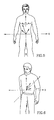
- Figs. 1A and 1B schematically illustrate a patient wearing an antenna array according to an embodiment of the present invention.
- an in-vivo signal source for example, an in-vivo image sensor may be located or localized using a portable or wearable antenna array or antenna array belt 10, as shown in Figs. 1A and 1B .
- the antenna array may be integral to a jacket that the patient may wear.
- the antenna array belt 10 may be fitted such that it may be wrapped around a patient and attached to a signal recorder 20.
- Additional embodiments include, for example, antenna elements having adhesive, which may adhere the element to a point on a body.
- Each of the antennas elements 10a through 10z in the array may connect via coaxial cables to a connector, which may connect to the recorder 20.
- Each antenna element 10a through 10z may be a loop antenna, a dipole antenna, or may be another suitable antenna configuration.
- the antenna array belt 10 may include, for example, 1 to eight antenna elements that may be typically positioned on a patient's midsection.
- the eight antenna elements can be positioned as follows: a first antenna element may be positioned approximately on the intersection of the right seventh intercostal space and right mid clavicular line; a second antenna element may be positioned approximately on the xiphoid process; a third antenna element may be positioned approximately on the intersection of the left 7th intercostal space and left mid clavicular line; a fourth antenna element may be positioned approximately on the right lumbar region at umbilical level; a fifth antenna element may be positioned approximately above the navel; a sixth antenna element may be positioned approximately on the left lumbar region at umbilical level; a seventh antenna element may be positioned approximately on the right mid-linguinal region; and an eighth antenna element may be positioned approximately on the left mid-linguinal region.
- Other antenna positions and other numbers of antennas may be used in accordance with embodiments of the invention. For example
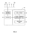
- Fig. 2 schematically illustrates a data recorder 20 according to an embodiment of the present invention.
- Data recorder 20 may include, for example, a data storage unit 22, a receiver 21, a signal strength measurement unit and/or a signal strength detector 24, a processing unit 26, and an antenna selector 25.
- the data recorder 20 may include other combinations of components, and the components described may be divided among several or other units.
- the antenna array may include a plurality of antennas wherein the antennas may receive a signal and/or information from a plurality of locations, for example by an RF signal, transmitted from the in-vivo image sensor.
- the signal strength measurement unit 24 may measure the signal strength of signals received by the receiver 21 from a plurality of locations, for example, from each of the antenna elements 10a through 10z.
- the processing unit 26 may perform calculations to correlate the received signal with an estimated location of the source of the signal.
- the antenna selector 25 may open a signal path to single one or more antenna elements from which the receiver 21 will receive a signal.
- the antenna selector 25 may be adjusted to scan through all or subset of antenna elements 10a through 10z.
- the scan rate and pattern may be adjusted, for example, to maximize Signal to Noise Ratios (SNRs) for the received signals.
- SNRs Signal to Noise Ratios
- Fig. 3 schematically illustrates an in-vivo signal source 100 according to an embodiment of the present invention.
- the source 100 may be a capsule, which may be ingested.
- the source 100 may include an in-vivo imaging or sensing device similar to an in-vivo imaging or sensing device known in the art, or may include an in-vivo imaging or sensing device having components similar to components known in the art.
- the source 100 may include one or more sensors, for example, a temperature sensor 110a, a pH sensor 110b, and an image sensor or optical sensor 110c. Other sensors or sets of sensors may be used. In some embodiments, only one sensor may be included in the source 100, e.g., an imaging sensor or an image sensor.
- the sensors 110 may provide data, for example, to a data transmitter 120.
- a beacon 130 may send out an intermittent beacon signal, or the beacon 130 may be instructed or configured to transmit at or about substantially the same time the data transmitter 120 transmits a data signal.
- the data transmitter 120 may transmit at a higher frequency than the beacon 130, but need not.
- the data transmitter 120 may transmit, for example, a non-modulated signal as a beacon signal. In some embodiments, a beacon and/or beacon signal need not be used.
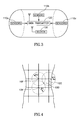
- Fig. 4 schematically illustrates a torso surrounded by an antenna array belt 10 according to an embodiment of the present invention and an estimated point of a signal source.
- a close-up of a human torso wearing a belt 10 or adhesive antenna array according to an embodiment of the present invention.
- an estimated location of an in-vivo signal source 100 is shown as the intersection point of three circles having radius R1, R2 and R3, each radius value being an estimated distance value of the source 100 from each of antenna elements 10k, 10f and 10g, respectively.
- the distance values may be calculated by a processing unit, e.g., by processing unit 26, based on signal strength measurements preformed by signal strength measurement unit 24.
- Equation 1 is presented for exemplary purposes, and that additional or alternate equations, functions, formulae, parameters, algorithms, assumptions and/or calculations may be used in accordance with embodiments of the invention.
- Other suitable signal source triangulation techniques may be used in accordance with embodiments of the invention.
- the assumption of linear attenuation may be valid at a working frequency range (e.g., 200-500 MHz) and at intermediate distances between the transmitter and receiver, i.e. for distances of half a wavelength to 2-2.5 wavelengths.
- Linear attenuation may be valid in between other frequencies and/or ranges.
- knowing the signal level at the source 100 and the measured signal level at each antenna, the distance between the source 100 and the antenna may be derived.
- Fig. 5 schematically illustrates three signal vectors in a two dimensional plane, in accordance with an embodiment of the invention.
- the three signal vectors may relate to signals received at three antenna elements, for example, 10d, 10p, 10q. Beginning at the origin of a coordinate system centered at the navel, each signal vector may point in the direction of its respective antenna element, and may have a magnitude relating to the strength of the received signal.
- each signal vector may be calculated, for example, as the product of a pointing vector from the origin to the point where its respective antenna element is placed, multiplied by a normalized received signal value.
- a normalized signal strength value may be computed, for example, by dividing each measured signal strength value by the strongest measured value. This may result in the strongest measured value being normalized to 1, and the rest to values less than one.
- the signal vector pointing to an antenna element receiving the strongest signal level may look substantially identical to its pointing vector, and the other signal vectors may be shorter than their pointing vectors.
- the estimated point or location of the signal source 100 may be estimated, for example, as the vector sum of all the signal strength vectors, i.e., the location vector.
- signal vectors may be calculated for two or more antenna elements 10a through 10z.
- signal vectors may be calculated for only elements placed at the front of the torso. In some embodiments, as illustrated schematically in Fig. 6 , signal vectors may be calculated for elements placed at the back of the body, as shown in Fig. 1B . In Fig. 6 , the point estimated to be the location of the signal source 100 is within the body. Typically, the location vector starts at the origin of a three dimensional system and ends at a point within the body.
- an absolute coordinate set may be used, wherein points on the body may be measured in terms of standard units, for example, centimeters or inches.
- values may be assigned relative to anatomical points on the body, and then the results may be normalized. For example, an antenna element placed approximately at the navel may be given the coordinate set 0,0; an element placed approximately at the right end of the torso at navel level may be given the coordinate set 5,0; and an element place at left end of the torso may be given the coordinate set -5,0.
- Distance values or vector magnitudes may be calculated using these coordinate sets, and then the values may be proportionally adjusted to fit the body's actual dimensions.
- the distance value of 2.5 could be adjusted in the same proportion, e.g., 7/5.
- only one or more, e.g., two or three or four, strongest signal sources may be used, rejecting the weaker signal strength values, to calculate signal vectors or distance values upon which a location estimate may be based.
- a second signal strength measurement may be performed.
- the processing unit 26 may be adapted to perform a conventional vector sum operation, for example, on a subset of the largest vectors, and to perform a weighted sum operation on the signal vectors which may be relatively smaller. Other suitable processing operations, calculations or estimations may be performed using one or more of the collected signals.
- the antenna selector 25 may be adjusted to perform a scan of only the antenna elements from which the strongest signals may have been received, excluding substantially all other antenna elements. In some embodiments, excluding or rejecting signal information from antennas providing weak signals, may increase Signal to Noise Ratios (SNRs).
- SNRs Signal to Noise Ratios
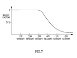
- location vectors or distance values may be calculated relating to many antenna elements, and signal vectors having relatively low magnitudes may be multiplied by a reducing factor or a weigh factor, e.g., as illustrated schematically in Fig. 7 .
- an estimated location of the in-vivo signal source 100 may be tracked substantially continuously or semi-continuously, for example, by a location detecting unit 15 ( Fig. 8 ).
- an instantaneous velocity vector for the signal source 100 may be computed, e.g., using the location information.
- the velocity vector may be the vector starting at the tip of a first location vector and ending at the tip of a consecutive location vector.
- the speed of the signal source 100 may be computed as a derivative of its position, and its direction or orientation may be plotted on a display or a graph functionally associated with the data recorder 20.
- a procedure for detecting a defective antenna elements may be used. For example, in some embodiment, if an antenna element may be determined to be defective, non-operational, semi-operational or malfunctioning, the entire trajectory may be invalidated. In one embodiment, for example, readings for all frames (if not discarded) may be collected, for each antenna, into two bins; for example, Bin1 having the number of readings in the range 0 to 40, and Bin2 having the number of readings in the range 41 to 255; or, for example, Bin1 having the number of readings in the range 0 to 107, and Bin2 having the number of readings in the range 108 to 255.
- the result may include, for example, eight histograms of two bins each, one for each antenna.
- Bin1/(Bin1+Bin2)>0.75 then the antenna may be determined to be defective, and otherwise the antenna may be determined to be functional.
- the trajectory may be considered valid, for example, if all antennas are determined to be functional.
- the Reception(n) ⁇ 60 (for the first example) or if the Reception(n) ⁇ 117 (for the second example) then the current sensor readings may be discarded.
- the parameter 'n' may represent one of the antennas, e.g. antennas 10f, 10g, or 10k, in the antenna array.
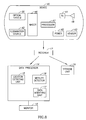
- FIG. 8 illustrates a schematic diagram of an in-vivo sensing system in accordance with an embodiment of the present invention.
- the system may include a device 40 having an image sensor 46, an illumination source 42, a power source 45, and a transmitter 41.
- Device 40 may be an example of signal source 100 of Fig. 3 .
- device 40 may be implemented using a swallowable capsule, but other sorts of devices or suitable implementations may be used.
- Outside a patient's body may be, for example, an image receiver 12 (including, for example, an antenna or an antenna array), a storage unit 19, a data processor 14, and a monitor 18.
- Data processor 14 may include a location detecting unit to detect and/or to construct, for example, a two dimensional tracking curve, for example, in substantially real time, of the location of device 40, for example, an in-vivo image sensor, over time as may be described herein. In other embodiments of the present invention, a three dimensional tracking curve may be constructed to track the location of the in-vivo sensing unit. According to some embodiments of the present invention, data processor 14 may include a data modifying unit 17 that may modify, for example, enhance at least some of the data obtained from location detecting unit 15.
- data processor 14 may include a motility detector 16 to detect, for example, if device 40 may be in motion at a given time and the data modifying unit 17 may, for example, enhance or modify data points sampled by the location detecting unit 15, for example, in substantially real time, as may be described herein.
- the motility detector 16 may for example compare image frames and/or data from image frames captured from device 40 in order to determine if device 40 advanced between capturing of frames, other methods of determining motility, for example, as a function of time may be implemented, for example by using sensors other than image sensors or using data from, for example, more than one sensor.
- the motility detector 16 may be integral to the data modifying unit 17.
- Other suitable methods of incorporating a location detecting unit 15, a motility detector 16, and a data modifying unit 17 may be implemented.
- motility detector 16 may be included in data modifying unit 17.
- Other suitable arrangements may be used.
- Transmitter 41 may operate using radio waves; but in some embodiments, such as those where device 40 may be or may be included within an endoscope, transmitter 41 may transmit data via, for example, wire, optical fiber and/or other suitable methods.
- Device 40 typically may be or may include an autonomous swallowable capsule, but device 40 may have other shapes and need not be swallowable or autonomous. Embodiments of device 40 may be typically autonomous, and may be typically self-contained. For example, device 40 may be a capsule or other unit where all the components may be substantially contained within a container or shell, and where device 40 may not require any wires or cables to, for example, receive power or transmit information.
- device 40 may communicate with an external receiving and display system 18 (e.g., through receiver 12) to provide display of data, control, or other functions.
- power may be provided to device 40 using an internal battery, an internal power source, or a wireless system to receive power.
- Other embodiments may have other configurations and capabilities. For example, components may be distributed over multiple sites or units, and control information may be received from an external source.
- device 40 may include an in-vivo video camera, for example, image sensor 46, which may capture and transmit images of, for example, the GI tract while device 40 may pass through, for example, the GI lumen. Other lumens and/or body cavities may be imaged and/or sensed by device 40.
- image sensor 46 may include, for example, a Charge Coupled Device (CCD) camera or image sensor, a Complementary Metal Oxide Semiconductor (CMOS) camera or image sensor, a digital camera, a stills camera, a video camera, or other suitable image sensors, cameras, or image acquisition components.
- CCD Charge Coupled Device
- CMOS Complementary Metal Oxide Semiconductor
- image sensor 46 in device 40 may be operationally connected to transmitter 41.
- Transmitter 41 may transmit images to, for example, image receiver 12, which may send the data to data processor 14 and/or to storage unit 19.
- Transmitter 41 may also include control capability, although control capability may be included in a separate component.
- Transmitter 41 may include any suitable transmitter able to transmit image data, other sensed data, and/or other data (e.g., control data) to a receiving device.
- transmitter 41 may include an ultra low power Radio Frequency (RF) high bandwidth transmitter, possibly provided in Chip Scale Package (CSP).
- RF Radio Frequency
- CSP Chip Scale Package
- Transmitter 41 may transmit via antenna 48.
- Transmitter 41 and/or another unit in device 40 may include control capability, for example, one or more control modules, processing module, circuitry and/or functionality for controlling device 40, for controlling the operational mode or settings of device 40, and/or for performing control operations or processing operations within device 40.
- control capability for example, one or more control modules, processing module, circuitry and/or functionality for controlling device 40, for controlling the operational mode or settings of device 40, and/or for performing control operations or processing operations within device 40.
- Power source 45 may include one or more batteries.
- power source 45 may include silver oxide batteries, lithium batteries, other suitable electrochemical cells having a high energy density, or the like. Other suitable power sources may be used.
- power source 45 may receive power or energy from an external power source (e.g., a power transmitter), which may be used to transmit power or energy to device 40.
- an external power source e.g., a power transmitter
- power source 45 may be internal to device 40, and/or may not require coupling to an external power source, e.g., to receive power. Power source 45 may provide power to one or more components of device 40 continuously, substantially continuously, or in a non-discrete manner or timing, or in a periodic manner, an intermittent manner, or an otherwise non-continuous manner. In some embodiments, power source 45 may provide power to one or more components of device 40, for example, not necessarily upon-demand, or not necessarily upon a triggering event or an external activation or external excitement.
- transmitter 41 may include a processing unit or processor or controller, for example, to process signals and/or data generated by image sensor 46.
- the processing unit may be implemented using a separate component within device 40, e.g., controller or processor 47, or may be implemented as an integral part of image sensor 46, transmitter 41, or another component, more than one component, or may not be needed.
- the optional processing unit may include, for example, a Central Processing Unit (CPU), a Digital Signal Processor (DSP), a microprocessor, a controller, a chip, a microchip, a controller, circuitry, an Integrated Circuit (IC), an Application-Specific Integrated Circuit (ASIC), or any other suitable multi-purpose or specific processor, controller, circuitry or circuit.
- the processing unit or controller may be embedded in or integrated with transmitter 41, and may be implemented, for example, using an ASIC.
- device 40 may include one or more illumination sources 42, for example one or more Light Emitting Diodes (LEDs), "white LEDs", or other suitable light sources.
- Illumination sources 42 may, for example, illuminate a body lumen or cavity being imaged and/or sensed.
- An optional optical system 50 including, for example, one or more optical elements, such as one or more lenses or composite lens assemblies, one or more suitable optical filters, or any other suitable optical elements, may optionally be included in device 40 and may aid in focusing reflected light onto image sensor 46 and/or performing other light processing operations.
- the components of device 40 may be enclosed within a housing or shell, e.g., capsule-shaped, oval, or having other suitable shapes.
- the housing or shell may be substantially transparent or semi-transparent, and/or may include one or more portions, windows or domes which may be substantially transparent or semi-transparent.
- one or more illumination source(s) 42 within device 40 may illuminate a body lumen through a transparent or semi-transparent portion, window or dome; and light reflected from the body lumen may enter the device 40, for example, through the same transparent or semi-transparent portion, window or dome, or, optionally, through another transparent or semi-transparent portion, window or dome, and may be received by optical system 50 and/or image sensor 46.
- optical system 50 and/or image sensor 146 may receive light, reflected from a body lumen, through the same window or dome through which illumination source(s) 42 illuminate the body lumen.
- image sensor 46 may acquire in-vivo images continuously, substantially continuously, or in a non-discrete manner, for example, not necessarily upon-demand, or not necessarily upon a triggering event or an external activation or external excitement; or in a periodic manner, an intermittent manner, or an otherwise non-continuous manner.
- transmitter 41 may transmit image data continuously, or substantially continuously, for example, not necessarily upon-demand, or not necessarily upon a triggering event or an external activation or external excitement; or in a periodic manner, an intermittent manner, or an otherwise non-continuous manner.
- Data processor 14 may analyze the data received via receiver 12 from device 40, and may be in communication with storage unit 19, e.g., transferring frame data to and from storage unit 19. Data processor 14 may also provide the analyzed data to monitor 18, where a user (e.g., a physician) may view or otherwise use the data. In one embodiment, data processor 14 may be configured for real time processing and/or for post processing to be performed and/or viewed at a later time. In the case that control capability (e.g., delay, timing, etc) may be external to device 40, a suitable external device (such as, for example, data processor 14 or image receiver 12) may transmit one or more control signals to device 40.
- control capability e.g., delay, timing, etc
- a suitable external device such as, for example, data processor 14 or image receiver 12
- Monitor 18 may include, for example, one or more screens, monitors, or suitable display units. Monitor 18, for example, may display one or more images or a stream of images captured and/or transmitted by device 40, e.g., images of the GI tract or of other imaged body lumen or cavity. Additionally or alternatively, monitor 18 may display, for example, tracking data, for example, in a least two dimensions, of the in-vivo sensor, control data, location or position data (e.g., data describing or indicating the location or the relative location of device 40), orientation data, and various other suitable data. In one embodiment, for example, both an image and its position or location may be presented using monitor 18 and/or may be stored using storage unit 19. Other systems and methods of storing and/or displaying collected image data and/or other data may be used.
- tracking data for example, in a least two dimensions, of the in-vivo sensor
- control data location or position data (e.g., data describing or indicating the location or the relative location of device 40), orientation data, and various other
- the system may provide information about the location of these conditions.
- Suitable tracking devices and methods are described in embodiments of the above-mentioned United States Patent Number 5,604,531 and/or United States Patent Application Number 10/150,018 , filed on May 20, 2002, entitled "Array System and Method for Locating an In-Vivo Signal Source", published on November 21, 2002 as United States Patent Application Publication Number 2002/0173718 , assigned to the common assignee of the present invention.
- Other suitable location identification systems and methods may be used in accordance with embodiments of the present invention.
- device 40 may transmit image information in discrete portions. Each portion may typically correspond to an image or a frame and/or may correspond to a few lines of image data; other suitable transmission methods may be used. For example, in some embodiments, device 40 may capture and/or acquire an image once every half second, and may transmit the image data to receiver 12. Other constant and/or variable capture rates and/or transmission rates may be used.
- the image data recorded and transmitted may include digital color image data; in alternate embodiments, other image formats (e.g., black and white image data) may be used.
- each frame of image data may include 256 rows, each row may include 256 pixels, and each pixel may include data for color and brightness according to known methods.
- a 320 by 320 pixels image sensor may be used. Pixel size may be, for example, between 5 to 6 microns.
- pixels may be each fitted with a micro lens
- color may be represented by a mosaic of four subpixels, each sub-pixel corresponding to primaries such as red, green, or blue (where one primary, e.g., green, may be represented twice).
- the brightness of the overall pixel may be recorded by, for example, a one byte (e.g., 0-255) brightness value.
- image data may be represented using an array of 64 by 64 pixels or super-pixels or boxes, each including data indicating values for red, green (repeated twice) and blue.
- Other suitable data formats may be used, and other suitable numbers or types of rows, columns, arrays, pixels, sub-pixels, boxes, super-pixels and/or colors may be used.
- device 40 may include one or more sensors 43, instead of or in addition to a sensor such as image sensor 46.
- Sensor 43 may, for example, sense, detect, determine and/or measure one or more values of properties or characteristics of the surrounding of device 40.
- sensor 43 may include a pH sensor, a temperature sensor, an electrical conductivity sensor, a pressure sensor, or any other known suitable in-vivo sensor.
- in-vivo device 40 may be an example of signal source 100
- portions of the discussion herein relating to signal source 100 relate also to device 40, and vice versa.
- the invention is not limited in this regard; the dimensions, directions, locations, axes and/or vectors may be relative, and in some embodiments, directions, directions, locations, axes and/or vectors may be swapped or exchanged, or other coordinate systems may be used.
- enhancement or alteration of localization and/or location data may be performed using, for example, data collected by or transmitted by an in-vivo device (e.g., device 40 or signal source 100), for example, data and/or information separate from location data itself
- location data may be inherent in a signal sent by the in-vivo device, or may be in a beacon sent by the in-vivo device, while other and additional data such as sensing data (e.g., image data, pH data, etc.) may be sent separately from location data.
- sensing data may be considered non-location data collected by the in-vivo device 40.
- location data may be inherent in a data signal that may primarily contain sensed data.
- more than one, for example two, possibly independent types of sensed data may be used to determine location and/or change in location.
- signal strength picked up from an in-vivo transmitting device 40 at one or more antennas as well as an image frame stream captured by the in-vivo device 40 may be used to determine location, tracking curve and/or change in location of an in-vivo device 40.
- the signal strength picked up may be the signal strength of the image frame stream captured by the in-vivo device 40 and received by more than one antenna.
- comparison of subsequent image frames may be instrumental in either confirming or refuting a change in the location of the in-vivo device 40 that may have been calculated based on the array of signal strengths over more than one antenna.
- both received signal strength as well as image data may be used to determine the location, change in location, or location curve, and/or tacking curve of an in-vivo device 40.
- data other than image data and/or signal strength data may be used to determine location and/or change in location and other data may be used to confirm and/or refute a change in location of an in-vivo device 40 determined based on one or more streams of data.
- temperature, pH, acceleration, oxygen saturation, or other sensed data sensed in-vivo may be used to determine location and/or change of location of an in-vivo device 40.
- sensed data transmitted out of the body and received by multiple antennas may be used together with the data corresponding to and/or carried on the received signal strength at one or more of the multiple antennas to determine the tracking curve, location of the vivo device 40, and/or motility.
- sensed data may determine and/or identify the body lumen within which the in-vivo device 40 may be located, for example in a specific lumen of the GI tract, e.g. esophagus, stomach, small intestine, large intestine, etc. Information regarding the lumen may help characterize the expected movement of the in-vivo device 40 in the identified lumen.
- an in-vivo device 40 may be currently located in the stomach area as may be determined based a pH sensor readings or other sensors readings (e.g. more than one sensor reading), the capsule may be expected to tumble and move in for example random directions.
- the tracking algorithm in this case may be adjusted, for example, to filter random motion in the displayed localization and/or tracking curve.
- Other suitable adjustments to the localization algorithm may be made based one or more types of sensed data.
- the in-vivo device 40 may be expected to advance in a more orderly manner. Independent information of this caliber may aid in increasing the coherency and/or usability of the localization data.
- knowledge of the body lumen within which the in-vivo device 40 may be located may help determine one or more specific directions that the capsule may be moving in. For example, through the esophagus most of the movement may be expected in a specific plane, for example in the X-Y plane, or some other plane, and sharp changes in for example the Z direction may be attributed to noise, for example.
- Other methods and other signals and/or data may be used to increase the coherency of the tracking curve of an in-vivo device 40.
- the in-vivo device 40 may be located in body lumens other than the GI lumens. Other methods of performing fusion of multiple data sources may be used to determine or improve location and/or motility information of the in-vivo device 40.
- the original location data may indicate that, for example, the device 40 may have been displaced, for example between two consecutive sampling points, a distance that may be assumed to be larger than may be considered probable or possible, for example, for a given region.
- one sampled point may indicate that device 40 may be in a location A and a subsequent sampled data point, sampled after, for example, one sampling period may indicate that device 40 may be in a location B.
- the distance between location A, a previous data point, and location B, a current data point may be larger than may be assumed probably or possible for device 40 to move during, for example, a single sample period.
- a current data point may be modified if its distance from a previous data point may be above a pre-determined threshold.
- a set and/or plurality of data point that may indicate displacement of the device 40 over a pre-determined threshold, the current data point, for example, sampling point B in the above example, may be repositioned to correspond to a displacement equaling to, for example, the pre-determined threshold, or other pre-determined value.
- the new position of the sampled data may be placed in the same relative direction of the original sampled point, for example sampled point B in the above example. As such the localization curve may be modified to eliminate substantially improbable displacements of the device 40.
- smoothing or filtering of localization data in one or more dimensions may be performed, for example, in substantially real time.
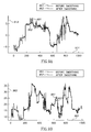
- Fig. 9A and 9B schematically illustrating a graph indicating for example an X-axis location (e.g., horizontal location) or an Y-axis location (e.g. vertical axis) of a sample signal source 100, for example, and image sensor as a function of and/or over time obtained from, for example a location detecting unit 15, the same sample signals after applying a median filter to reduce noise.
- Fig. 9A and 9B may be representative of other suitable axis or dimensions besides or in addition to the X-axis and Y-axis.
- median filtering may be included in data modifying unit 17 and may be performed in, for example, real time. In other embodiments, median filtering may included in other suitable units.
- a horizontal axis 911 may indicate, for example, image frame number, time units, or received data packets or other data.
- a marking "400" on the horizontal axis 911 may indicate that 400 frames were received by recorder 20 or receiver 12. This may indicate, for example, that 200 seconds elapsed, if frames may be transmitted by signal source 100 at a rate of, for example, two frames per second.
- a vertical axis 912 may indicate, for example, an X-axis location (e.g., a horizontal location) of signal source 100.
- the marking "5" on the vertical axis 912 may indicate an X-axis location of 5 centimeters, wherein a pre-defined location (e.g., approximately over the navel) may be pre-defined as having a "0" X-axis value.
- Other measurement units may be used, and other points of reference may be used. Normalization may be applied so to the horizontal and/or vertical axis or other suitable units may be used.
- a graph 901 may represent the X-axis location of signal source 100 in-vivo as a function of frame numbers or elapsed time.
- graph 901 may be enhanced, corrected, refined, modified or otherwise processed, for example, to allow more-reliable tracking of signal source 100 and to eliminate or decrease potential inaccuracies.
- Such enhancement or processing may be performed, for example, by data modifying unit 17, by recorder 20, by processing unit 26, by receiver 12 or by data processor 14, or by another suitable unit.
- the enhancement or processing may include, for example, smoothing of graph 901 and/or of data presentable using graph 901, e.g., using linear smoothing, using average smoothing, using non-linear smoothing, for example using median smoothing or filtering.
- data representing X-axis location of signal source 100 may be subject to median smoothing or median filtering, and graph 901 may be modified or processed to result in an enhanced graph, e.g., a graph 902.
- median filtering may be applied to preserve sharp transitions that may be inherent in motility of device 40 while filtering out noise.
- the results of the median smoothing may be further used, for example, to display or store enhanced localization data of signal source 100.
- the parameters defming the median filter or other suitable filter may be defined based on knowledge of the motility of device 40 within the body lumen. For example the degree of smoothing may be adjusted to reflect a rate at which device 40 may be expected to advance through a body lumen, so that a calculated or generated gradient or slope that may reflect a rate above which device 40 may be expected to advance may be smoothed out using one or more suitable smoothing techniques, e.g. median filters.
- suitable smoothing techniques e.g. median filters.
- a horizontal axis 961 may indicate, for example, image frame number, time units, or received data packets or other data.
- a marking "400" on the horizontal axis 961 may indicate that 400 frames were received by recorder 20 or receiver 12. This may indicate, for example, that 200 seconds elapsed, if frames may be transmitted by signal source 100, for example, at a rate of two frames per second.
- a vertical axis 962 may indicate, for example, a Y-axis location (e.g., a vertical location) of signal source 100.
- the marking "10" on the vertical axis 912 may indicate a Y-axis location of 10 centimeters, wherein a pre-defined location (e.g., approximately over the navel) may be pre-defined as having a "0" Y-axis value.
- Other measurement units may be used, and other points of reference may be used.
- a graph 951 may represent the Y-axis location of signal source 100 in-vivo as a function of frame numbers or elapsed time.
- graph 951 may be enhanced, corrected, refined, modified or otherwise processed by for example, data modifying unit 17, for example, to allow a more-reliable and/or coherent localization of signal source 100 and to eliminate or decrease potential inaccuracies for example, inaccuracies due to noise or due to random movement of the capsule, e.g. change in the orientation of the capsule.
- Data modifying unit 17 may be integral to, for example, recorder 20, processing unit 26, receiver 12 and/or data processor 14, or by another suitable unit.
- the enhancement or processing by, for example, data modifying unit 17 may include, for example, smoothing of graph 951 and/or of data presentable using graph 951, e.g., using linear smoothing, using average smoothing, or using median smoothing.
- data representing Y-axis location of signal source 100 may be subject to median smoothing or median filtering, for example in substantially real time, and graph 951 may be modified or processed to result in an enhanced graph, e.g., a graph 952.
- the results of the median smoothing may be further used, for example, to display or store enhanced localization data of signal source 100.
- some embodiments may use X-axis localization data or graph enhancement, Y-axis localization data or graph enhancement, or both X-axis and Y-axis localization data or graph enhancement.
- both X-axis and Y-axis localization data or graph enhancement may be subject to median smoothing or median filtering.
- median-filtered localization data or graphs may be stored, displayed or processed, instead of or in addition to non-enhanced data.
- axes may be, but need not be, perpendicular to each other, or substantially parallel to a person's body or skin.
- median filtering, median smoothing, and/or other suitable methods of filtering, smoothing or enhancing may be performed on localization signals, localization data, localization graphs, motility data, or images or visual representations corresponding to localization data.
- the filtering, smoothing or enhancement may be performed substantially in real time, e.g., upon reception of localization signals and while the signal source 100 may be in-vivo.
- the filtering, smoothing or enhancement may be performed at a later period of time, e.g., during post-processing of previously-collected localization data.
- a tracking curve may have a "digitized" or jagged look when displayed, and curve smoothing (e.g., X-Z, Y-Z, and/or X-Y curve smoothing) may be applied to enhance and improve the location data. This may be performed, for example, while maintaining the relative locations of location data points on the tracking curve. It is noted that in some embodiments, smoothing of tracking curves may be different than smoothing each of two one-dimensional vector points since for example there may be no uniform spacing of the points on a two-dimensional tracking curve.
- curve smoothing e.g., X-Z, Y-Z, and/or X-Y curve smoothing
- location data curve smoothing may be performed by for example, data modifying unit 17, using a suitable algorithm, method or process.
- the length of the curve may be calculated or determined; and the distance of each point on the curve, relative to the start of the curve, may be determined.
- the values of each of two one-dimension sampled vectors may be smoothed using a suitable method, e.g., using boxcar smoothing as known in the art.
- the curve may be re-sampled in a spatial plane, substantially uniformly, along the curve line.
- the smoothed vectors may be re-sampled at the relative original positions. This may result in, for example, a data location graph having smooth curves or relatively smooth curves, which may be used for further display, storage or processing.
- certain location data calculated by recorder 20 based on received signals may be over-ruled, disregarded, discarded, not used or not displayed, when one or more pre-defined conditions may be met.
- data points sampled from the location detecting unit 15 that may indicate, for example, that signal source 100 may have moved from a first location to a second location may be disregarded when one or more pre-defined conditions may be met.
- motility of device 40 may be determined in the motility detecting unit 16 and may be used to determine the one or more pre-defined conditions.
- a first image and a second image e.g., two consecutive images received from signal source 100, in-vivo device 40 or image sensor 46, are compared and determined to be identical, substantially identical or generally identical, and/or indicate non-movement of the image sensor then it may be determined that the location of signal source 100 or in-vivo-device 40 may not have changed at the time period between acquiring the first image and acquiring the second image.
- the location detecting unit 15 that may indicate a movement of device 40 may be over-ruled, discarded, replaced with a data point indicating non-movement of device 40, or replaced with data sampled by the location detecting unit associated with a previous location of device 40.
- two or more images acquired by in-vivo device 40 may be compared or otherwise analyzed, for example, by motility detector 16 in order to generate data to track device 40 in-vivo, or in order to generate analysis results which may be used to enhance or modify localization data.
- the comparison or analysis of images for example, as may be performed in the motility detector 16, may be in accordance with methods and algorithms known in the art, for example, as described in United States Patent Number 6,709,387 , entitled "System and method for controlling in-vivo camera capture and display rate".
- the comparison or analysis may result in, for example, a conclusion that the in-vivo device 40 may be moving or may not be moving, and data point(s) sampled from the location detecting unit 15 may be updated in the data modifying unit 17 according to the analysis or comparison results, for example, the comparison results performed in the motility detector 16.
- motility detector 16 may implement information other or in addition to image information to detect motility of device 40.
- image comparison, image processing, or image analysis may be used as one of the parameters that a data modifying unit 17 may take into account.
- the image comparison or image analysis may influence in reducing the noise of data sampled from a location detecting unit, such that an image comparison result indicating non-movement of device 40 may result in modifying the location data to correspond to such non-movement.
- non-linear smoothing e.g median filtering may be used on data sampled from the location detecting unit 15 when device 40 may be determined to be in motion; and image comparison may be used in the motility detector 16 to determine, at a different time, for example that device 40 may not be moving and therefore data points sampled by location detecting unit may be modified to indicate such non-movement.
- image comparison may be used in the motility detector 16 to determine, at a different time, for example that device 40 may not be moving and therefore data points sampled by location detecting unit may be modified to indicate such non-movement.
- Other suitable analysis based on other sensors may be used to enhance or determine location and/or change in location and/or tracking curve.
- Fig. 10 is a flow-chart diagram of a method of processing data points sampled by location detecting unit 15 tracking in-vivo signal source in accordance with an embodiment of the present invention.
- the method of Fig. 10 may be used, for example, in association with the antenna array of Figs. 1A-1B , with recorder 20 of Fig. 2 , with processing unit 26 of Fig 2 , with signal source 100 of Fig. 3 , with device 40 of Fig. 8 , with the system of Fig. 8 , and/or with other suitable devices and systems for in-vivo imaging or in-vivo sensing.
- a method according to embodiments of the invention need not be used in an in-vivo context.
- the method includes, for example, receiving and/or sampling data points from location detecting unit 15. This may be performed, for example, by recorder 20 of Fig. 2 .
- the data modifying in data modifying unit 17 may optionally include, for example, applying a smoothing or a filtering process, for example, median filtering or other scheme to at least a portion of the data points sampled from the location detecting unit 15. In some embodiment, this may include, for example, applying linear averaging or non-linear averaging to at least a portion of the location data or location signals. In some embodiments, the operations of box 1020 may include, for example, applying median smoothing or median filtering to at least a portion of the localization data or localization signals. Other filtering or smoothing operations may be performed in accordance with embodiments of the invention by data modifying unit 17.
- a smoothing or a filtering process for example, median filtering or other scheme
- the method may optionally include constructing a two dimensional tracking curve may be from data obtained from, for example the location detection unit 15.
- a three dimensional tracking curve or other suitable tracking curves may be constructed and displayed.
- the plane that may be defined by two dimensions may represent, for example, the plane where most of the movement of device 40 through for example the GI tract may occur, for example it may be coronal plane, substantially the coronal plane, or any other suitable plane.
- the tracking curve may be, for example, a tracking curve of device 40 in the substantially coronal plane.
- the method may optionally include determining distances between point on the tracking curve.
- the distance determined may be the distance within the two dimensional plane or may be the distance in three dimensional space. Distances may be compared to thresholds, as may be described herein or may be used for other suitable analysis.
- the method may optionally include, for example, applying a curve smoothing process or scheme, for example, to the tracking curve obtained, to at least a portion of the data points sampled in at least two dimensions by location detecting unit 15 in, for example, substantially real time.
- data modification by data modification unit 17 may include, for example, applying an X-Z curve smoothing process to at least a portion of the location data or location signals.
- Other curve smoothing operations may be performed as may have been described herein and may be in accordance with embodiments of the invention.
- the data modification by data modification unit 17 includes, for example, processing or modifying data points sampled from location detecting unit in relation to, or based on, information sensed or imaged by an in-vivo device and/or in-vivo image sensor.
- the method may include, motility detection by motility detector 16, for example, comparing between two or more images acquired by the in-vivo imaging device, or analyzing one or more images acquired by the in-vivo imaging device.
- location data may be updated or modified, e.g., to indicate non-movement of the in-vivo imaging device at that time period.
- image content or comparison may be used in other ways to modify location data sampled by location detecting unit 15.
- modification of data points sampled by location detecting unit 15 may be performed prior to filtering, prior to curve smoothing, or in other suitable order.
- the method may optionally include, for example, performing other suitable operations, e.g., storing the modified location data points or signals, printing the location data or signals, displaying the location data or signals, or otherwise processing the location data or signals.
- performing other suitable operations e.g., storing the modified location data points or signals, printing the location data or signals, displaying the location data or signals, or otherwise processing the location data or signals.
- a device, system and method in accordance with some embodiments of the invention may be used, for example, in conjunction with a device which may be inserted into a human body.
- a device which may be inserted into a human body may be used, for example, in conjunction with a device which may be inserted into a human body.
- the scope of the present invention is not limited in this regard.
- some embodiments of the invention may be used in conjunction with a device which may be inserted into a non-human body or an animal body.
- Embodiments of the invention may be implemented by software, by hardware, or by any combination of software and/or hardware as may be suitable for specific applications or in accordance with specific design requirements.
- Embodiments of the invention may include units and/or sub-units, which may be separate of each other or combined together, in whole or in part, and may be implemented using specific, multi-purpose or general processors, circuits or controllers, or devices as are known in the art.
- Some embodiments of the invention may include buffers, registers, storage units and/or memory units, for temporary or long-term storage of data or in order to facilitate the operation of a specific embodiment.
- Some embodiments of the invention may be implemented, for example, using a machine-readable medium or article which may store an instruction or a set of instructions that, if executed by a machine, for example, by device 100, by device 40, by processor 14, by data modifying unit 17, motility detector 16, location detecting unit 15 or by other suitable machines, may cause the machine to perform a method and/or operations in accordance with embodiments of the invention.
- a machine may include, for example, any suitable processing platform, computing platform, computing device, processing device, computing system, processing system, computer, processor, or the like, and may be implemented using any suitable combination of hardware and/or software.
- the machine-readable medium or article may include, for example, any suitable type of memory unit, memory device, memory article, memory medium, storage device, storage article, storage medium and/or storage unit, for example, memory, removable or non-removable media, erasable or non-erasable media, writeable or rewriteable media, digital or analog media, hard disk, floppy disk, Compact Disk Read Only Memory (CD-ROM), Compact Disk Recordable (CD-R), Compact Disk ReWriteable (CD-RW), optical disk, magnetic media, various types of Digital Versatile Disks (DVDs), a tape, a cassette, or the like.
- any suitable type of memory unit for example, any suitable type of memory unit, memory device, memory article, memory medium, storage device, storage article, storage medium and/or storage unit, for example, memory, removable or non-removable media, erasable or non-erasable media, writeable or rewriteable media, digital or analog media, hard disk, floppy disk, Compact Disk Read Only Memory (
- the instructions may include any suitable type of code, for example, source code, compiled code, interpreted code, executable code, static code, dynamic code, or the like, and may be implemented using any suitable high-level, low-level, object-oriented, visual, compiled and/or interpreted programming language, e.g., C, C++, Java, BASIC, Pascal, Fortran, Cobol, assembly language, machine code, or the like.
- code for example, source code, compiled code, interpreted code, executable code, static code, dynamic code, or the like
- suitable high-level, low-level, object-oriented, visual, compiled and/or interpreted programming language e.g., C, C++, Java, BASIC, Pascal, Fortran, Cobol, assembly language, machine code, or the like.
Claims (10)
- System zum Nachverfolgen eines In-Vivo-Bildsensors (46), das System mit:einer Positionserkennungseinheit (15), um den In-Vivo-Bildsensor (46) über der Zeit zu lokalisieren;einer Datenverändetungseinheit (17), um Daten, die von der Positionserkennungseinheit (15) aufgenommen wurden, basierend auf Information zu verändern, die vom In-Vivo-Bildsensor (46) erfasst wurde;einem Signalstärkedetektor (24); undzumindest einer Antenne (10), wobei die Antenne (10) dafür ausgebildet ist, ein Signal zu empfangen, das von dem In-Vivo-Bildsensor (46) gesendet wurde.
- System nach Anspruch 1, wobei die Datenveränderungseinheit (17) dafür ausgebildet ist, die Daten im Wesentlichen in Echtzeit zu verändern.
- System nach Anspruch 1 oder 2, wobei die Datenvcränderungseinheit (17) einen Median-Filter aufweist.
- System nach einem der Ansprüche 1 bis 3, wobei der In-Vivo-Bildsensor (46) dafür ausgebildet ist, In-Vivo-Bilder zu erfassen.
- System nach einem der Ansprüche 1 bis 4, wobei die Datenveränderungseinheit (17) einen Bewegungsdetektor (16) aufweist.
- System nach Anspruch 5, wobei der Bewegungsdetektor (16) dafür ausgebildet ist, Bilder zu vergleichen, die von dem In-Vivo-Bildsensor (46) erfasst wurden.
- System nach einem der Ansprüche 1 bis 6, mit einer Anzeigeeinheit (18), um Nachverfolgungsinformation des In-Vivo-Bildsensors (46) darzustellen.
- System nach einem der Ansprüche 1 bis 7, wobei der In-Vivo-Bildsensor (46) autonom ist.
- System nach einem der Ansprüche 1 bis 8 mit einer schluckbaren Kapsel (40), die den In-Vivo-Bildsensor (46) aufweist.
- System nach einem der Ansprüche 1 bis 8 mit:einer schluckbaren Kapsel (40), die mindestens den In-Vivo-Bildsensor (46) und einen Sender (41) zum Übertragen von Bilddaten aufweist;einem Antennenarray (10), um Signale zu empfangen, die von dem Sender (41) gesendet wurden; undeiner Aufnahmeeinheit (19), um die empfangenen Signale aufzunehmen.
Applications Claiming Priority (1)
| Application Number | Priority Date | Filing Date | Title |
|---|---|---|---|
| US63996404P | 2004-12-30 | 2004-12-30 |
Publications (2)
| Publication Number | Publication Date |
|---|---|
| EP1676522A1 EP1676522A1 (de) | 2006-07-05 |
| EP1676522B1 true EP1676522B1 (de) | 2008-07-02 |
Family
ID=36076896
Family Applications (1)
| Application Number | Title | Priority Date | Filing Date |
|---|---|---|---|
| EP05112932A Not-in-force EP1676522B1 (de) | 2004-12-30 | 2005-12-23 | System zur Lokalisation einer in-Vivo Signalquelle |
Country Status (6)
| Country | Link |
|---|---|
| US (1) | US20060183993A1 (de) |
| EP (1) | EP1676522B1 (de) |
| JP (1) | JP5357378B2 (de) |
| AT (1) | ATE399501T1 (de) |
| DE (1) | DE602005007847D1 (de) |
| IL (1) | IL172917A (de) |
Cited By (2)
| Publication number | Priority date | Publication date | Assignee | Title |
|---|---|---|---|---|
| US8617058B2 (en) | 2008-07-09 | 2013-12-31 | Innurvation, Inc. | Displaying image data from a scanner capsule |
| US8647259B2 (en) | 2010-03-26 | 2014-02-11 | Innurvation, Inc. | Ultrasound scanning capsule endoscope (USCE) |
Families Citing this family (95)
| Publication number | Priority date | Publication date | Assignee | Title |
|---|---|---|---|---|
| IL143260A (en) * | 2001-05-20 | 2006-09-05 | Given Imaging Ltd | Array and method for locating an intra-body signal source |
| JP4520198B2 (ja) * | 2004-04-07 | 2010-08-04 | オリンパス株式会社 | 被検体内位置表示システム |
| US8730031B2 (en) | 2005-04-28 | 2014-05-20 | Proteus Digital Health, Inc. | Communication system using an implantable device |
| CN101287411B (zh) | 2005-04-28 | 2013-03-06 | 普罗秋斯生物医学公司 | 药物信息系统及其用途 |
| US8836513B2 (en) | 2006-04-28 | 2014-09-16 | Proteus Digital Health, Inc. | Communication system incorporated in an ingestible product |
| US8802183B2 (en) | 2005-04-28 | 2014-08-12 | Proteus Digital Health, Inc. | Communication system with enhanced partial power source and method of manufacturing same |
| US9198608B2 (en) | 2005-04-28 | 2015-12-01 | Proteus Digital Health, Inc. | Communication system incorporated in a container |
| US8912908B2 (en) | 2005-04-28 | 2014-12-16 | Proteus Digital Health, Inc. | Communication system with remote activation |
| JP5714210B2 (ja) | 2005-09-01 | 2015-05-07 | プロテウス デジタル ヘルス, インコーポレイテッド | 移植可能なワイヤ無し通信システム |
| US8526688B2 (en) * | 2006-03-09 | 2013-09-03 | General Electric Company | Methods and systems for registration of surgical navigation data and image data |
| KR20140018439A (ko) | 2006-05-02 | 2014-02-12 | 프로테우스 디지털 헬스, 인코포레이티드 | 환자 주문형 치료법 |
| WO2008030480A2 (en) | 2006-09-06 | 2008-03-13 | Innurvation, Inc. | Ingestible low power sensor device and system for communicating with same |
| WO2008030482A2 (en) | 2006-09-06 | 2008-03-13 | Innurvation Inc | System and method for acoustic information exchange involving an ingestible low power capsule |
| US20080084478A1 (en) * | 2006-09-28 | 2008-04-10 | Zvika Gilad | System and method for an in-vivo imaging device with an angled field of view |
| WO2008066617A2 (en) | 2006-10-17 | 2008-06-05 | Proteus Biomedical, Inc. | Low voltage oscillator for medical devices |
| US7761134B2 (en) * | 2006-10-20 | 2010-07-20 | Given Imaging Ltd. | System and method for modeling a tracking curve of an in vivo device |
| EP2083680B1 (de) | 2006-10-25 | 2016-08-10 | Proteus Digital Health, Inc. | Einnehmbarer identifikator mit kontrollierer aktivierung |
| WO2008063626A2 (en) | 2006-11-20 | 2008-05-29 | Proteus Biomedical, Inc. | Active signal processing personal health signal receivers |
| WO2008076910A1 (en) * | 2006-12-15 | 2008-06-26 | The Board Of Trustees Of The Leland Stanford Junior University | Image mosaicing systems and methods |
| SG178740A1 (en) | 2007-02-01 | 2012-03-29 | Proteus Biomedical Inc | Ingestible event marker systems |
| WO2008101107A1 (en) | 2007-02-14 | 2008-08-21 | Proteus Biomedical, Inc. | In-body power source having high surface area electrode |
| WO2008112578A1 (en) | 2007-03-09 | 2008-09-18 | Proteus Biomedical, Inc. | In-body device having a deployable antenna |
| US8932221B2 (en) | 2007-03-09 | 2015-01-13 | Proteus Digital Health, Inc. | In-body device having a multi-directional transmitter |
| DE602008001523D1 (de) * | 2007-04-11 | 2010-07-29 | Given Imaging Ltd | In-vivo-Fühlervorrichtungen und Verfahren zur Identifizierung |
| US8540632B2 (en) | 2007-05-24 | 2013-09-24 | Proteus Digital Health, Inc. | Low profile antenna for in body device |
| EP2008584A1 (de) | 2007-06-26 | 2008-12-31 | Julius-Maximilians-Universität Würzburg | In-vivo-Vorrichtung, System und Verwendung davon |
| FI2192946T3 (fi) | 2007-09-25 | 2022-11-30 | Elimistön sisäinen laite, jossa on virtuaalinen dipolisignaalinvahvistus | |
| US20100222670A1 (en) * | 2007-10-04 | 2010-09-02 | Michel Demierre | Device for measuring and method for analysing gastrointestinal motility |
| US9197470B2 (en) | 2007-10-05 | 2015-11-24 | Innurvation, Inc. | Data transmission via multi-path channels using orthogonal multi-frequency signals with differential phase shift keying modulation |
| JP5794782B2 (ja) * | 2007-11-27 | 2015-10-14 | プロテウス デジタル ヘルス, インコーポレイテッド | 通信チャネルを採用するトランスボディ通信システム |
| US20090171148A1 (en) * | 2007-12-27 | 2009-07-02 | Shih-Chieh Lu | Capsule endoscope system having a sensing and data discriminating device and discrimination method thereof |
| DK3235491T3 (da) | 2008-03-05 | 2021-02-08 | Otsuka Pharma Co Ltd | Spiselige hændelsesmarkeringsenheder og systemer med multimodus-kommunikation |
| JP5296396B2 (ja) * | 2008-03-05 | 2013-09-25 | オリンパスメディカルシステムズ株式会社 | 生体内画像取得装置、生体内画像受信装置、生体内画像表示装置およびノイズ除去方法 |
| US8406490B2 (en) * | 2008-04-30 | 2013-03-26 | Given Imaging Ltd. | System and methods for determination of procedure termination |
| US8185354B2 (en) * | 2008-05-19 | 2012-05-22 | The Procter & Gamble Company | Method of determining the dynamic location of a protection device |
| US8260578B2 (en) * | 2008-05-19 | 2012-09-04 | The Procter & Gamble Company | Method of determining the dynamic location of a protection |
| US20090312627A1 (en) * | 2008-06-16 | 2009-12-17 | Matott Laura A | Radio-labeled ingestible capsule |
| CA2730275C (en) | 2008-07-08 | 2019-05-21 | Proteus Biomedical, Inc. | Ingestible event marker data framework |
| EP2313003B1 (de) | 2008-08-13 | 2016-08-03 | Proteus Digital Health, Inc. | Einnehmbarer schaltkreis |
| JP5411943B2 (ja) | 2008-11-13 | 2014-02-12 | プロテウス デジタル ヘルス, インコーポレイテッド | 摂取可能な治療起動装置システムおよび方法 |
| WO2010068818A2 (en) * | 2008-12-11 | 2010-06-17 | Proteus Biomedical, Inc. | Evaluation of gastrointestinal function using portable electroviscerography systems and methods of using the same |
| US9659423B2 (en) | 2008-12-15 | 2017-05-23 | Proteus Digital Health, Inc. | Personal authentication apparatus system and method |
| US9439566B2 (en) | 2008-12-15 | 2016-09-13 | Proteus Digital Health, Inc. | Re-wearable wireless device |
| TWI424832B (zh) | 2008-12-15 | 2014-02-01 | Proteus Digital Health Inc | 與身體有關的接收器及其方法 |
| US9883819B2 (en) | 2009-01-06 | 2018-02-06 | Proteus Digital Health, Inc. | Ingestion-related biofeedback and personalized medical therapy method and system |
| EP2385827B1 (de) | 2009-01-06 | 2018-07-04 | Proteus Digital Health, Inc. | System zur dosierten verabreichung von arzneimitteln |
| WO2010111403A2 (en) | 2009-03-25 | 2010-09-30 | Proteus Biomedical, Inc. | Probablistic pharmacokinetic and pharmacodynamic modeling |
| EP2413786B1 (de) * | 2009-03-31 | 2015-05-20 | Given Imaging, Inc., | Verfahren zur bestimmung des körperaustritts einer eingenommenen kapsel |
| SG175388A1 (en) | 2009-04-28 | 2011-12-29 | Proteus Biomedical Inc | Highly reliable ingestible event markers and methods for using the same |
| WO2010132331A2 (en) | 2009-05-12 | 2010-11-18 | Proteus Biomedical, Inc. | Ingestible event markers comprising an ingestible component |
| EP2467707A4 (de) | 2009-08-21 | 2014-12-17 | Proteus Digital Health Inc | Vorrichtung und verfahren zur messung biologischer parameter |
| CN101711673B (zh) * | 2009-10-16 | 2012-11-21 | 重庆金山科技(集团)有限公司 | 食道酸碱度无线监测定位系统、装置及方法 |
| US9192353B2 (en) | 2009-10-27 | 2015-11-24 | Innurvation, Inc. | Data transmission via wide band acoustic channels |
| TWI517050B (zh) | 2009-11-04 | 2016-01-11 | 普羅托斯數位健康公司 | 供應鏈管理之系統 |
| UA109424C2 (uk) | 2009-12-02 | 2015-08-25 | Фармацевтичний продукт, фармацевтична таблетка з електронним маркером і спосіб виготовлення фармацевтичної таблетки | |
| BR112012019212A2 (pt) | 2010-02-01 | 2017-06-13 | Proteus Digital Health Inc | sistema de coleta de dados |
| SG184494A1 (en) | 2010-04-07 | 2012-11-29 | Proteus Biomedical Inc | Miniature ingestible device |
| TWI557672B (zh) | 2010-05-19 | 2016-11-11 | 波提亞斯數位康健公司 | 用於從製造商跟蹤藥物直到患者之電腦系統及電腦實施之方法、用於確認將藥物給予患者的設備及方法、患者介面裝置 |
| US8318892B2 (en) * | 2010-07-28 | 2012-11-27 | Xerox Corporation | Capped structured organic film compositions |
| JP5242852B2 (ja) * | 2010-09-28 | 2013-07-24 | オリンパスメディカルシステムズ株式会社 | 画像表示装置及びカプセル型内視鏡システム |
| WO2012042986A1 (ja) | 2010-09-29 | 2012-04-05 | オリンパスメディカルシステムズ株式会社 | 情報処理装置及びカプセル型内視鏡システム |
| EP2642983A4 (de) | 2010-11-22 | 2014-03-12 | Proteus Digital Health Inc | Einnehmbare vorrichtung mit einem pharmazeutischen produkt |
| JP5657375B2 (ja) * | 2010-12-24 | 2015-01-21 | オリンパス株式会社 | 内視鏡装置及びプログラム |
| JP2014514032A (ja) | 2011-03-11 | 2014-06-19 | プロテウス デジタル ヘルス, インコーポレイテッド | 様々な物理的構成を備えた着用式個人身体関連装置 |
| EP2617346B1 (de) * | 2011-05-30 | 2017-09-06 | Olympus Corporation | Antennenvorrichtung, antenne und antennenhalter |
| US9756874B2 (en) | 2011-07-11 | 2017-09-12 | Proteus Digital Health, Inc. | Masticable ingestible product and communication system therefor |
| WO2015112603A1 (en) | 2014-01-21 | 2015-07-30 | Proteus Digital Health, Inc. | Masticable ingestible product and communication system therefor |
| KR101898964B1 (ko) | 2011-07-21 | 2018-09-14 | 프로테우스 디지털 헬스, 인코포레이티드 | 모바일 통신 장치, 시스템, 및 방법 |
| WO2013018464A1 (ja) * | 2011-07-29 | 2013-02-07 | オリンパスメディカルシステムズ株式会社 | 位置検出装置、カプセル型内視鏡システムおよびカプセル型内視鏡の位置検出プログラム |
| US9107604B2 (en) | 2011-09-26 | 2015-08-18 | Given Imaging Ltd. | Systems and methods for generating electromagnetic interference free localization data for an in-vivo device |
| US9235683B2 (en) | 2011-11-09 | 2016-01-12 | Proteus Digital Health, Inc. | Apparatus, system, and method for managing adherence to a regimen |
| JP5502248B1 (ja) * | 2012-04-26 | 2014-05-28 | オリンパスメディカルシステムズ株式会社 | 位置検出装置、カプセル型内視鏡システム、及び位置検出プログラム |
| BR112015001388A2 (pt) | 2012-07-23 | 2017-07-04 | Proteus Digital Health Inc | técnicas para fabricar marcadores de eventos ingeríveis que compreendem um componente ingerível |
| ES2683709T3 (es) | 2012-10-18 | 2018-09-27 | Proteus Digital Health, Inc. | Aparato, sistema, y procedimiento para optimizar de manera adaptativa la disipación de energía y la energía de difusión en una fuente de energía para un dispositivo de comunicación |
| RU2537762C2 (ru) * | 2013-01-15 | 2015-01-10 | Лемарк Михайлович Клюкин | Способ и устройство для полуавтоматического диагностирования патологий молочных желез |
| RU2537763C2 (ru) * | 2013-01-17 | 2015-01-10 | Лемарк Михайлович Клюкин | Способ и устройство для полуавтоматического диагностирования патологий тела пациента |
| US11149123B2 (en) | 2013-01-29 | 2021-10-19 | Otsuka Pharmaceutical Co., Ltd. | Highly-swellable polymeric films and compositions comprising the same |
| JP6498177B2 (ja) | 2013-03-15 | 2019-04-10 | プロテウス デジタル ヘルス, インコーポレイテッド | 本人認証装置システムおよび方法 |
| JP5941240B2 (ja) | 2013-03-15 | 2016-06-29 | プロテウス デジタル ヘルス, インコーポレイテッド | 金属検出器装置、システム、および方法 |
| EP3005281A4 (de) | 2013-06-04 | 2017-06-28 | Proteus Digital Health, Inc. | System, vorrichtung und verfahren zur datensammlung und ergebnisbeurteilung |
| JP6475699B2 (ja) | 2013-06-05 | 2019-02-27 | チェック−キャップ リミテッドCheck−Cap Ltd. | 消化管の造影用カプセルの位置推定 |
| US9796576B2 (en) | 2013-08-30 | 2017-10-24 | Proteus Digital Health, Inc. | Container with electronically controlled interlock |
| AU2014321320B2 (en) | 2013-09-20 | 2019-03-14 | Otsuka Pharmaceutical Co., Ltd. | Methods, devices and systems for receiving and decoding a signal in the presence of noise using slices and warping |
| US9577864B2 (en) | 2013-09-24 | 2017-02-21 | Proteus Digital Health, Inc. | Method and apparatus for use with received electromagnetic signal at a frequency not known exactly in advance |
| US10084880B2 (en) | 2013-11-04 | 2018-09-25 | Proteus Digital Health, Inc. | Social media networking based on physiologic information |
| JP2017524444A (ja) | 2014-07-10 | 2017-08-31 | ギブン イメージング リミテッドGiven Imaging Ltd. | 生体内デバイスを位置特定するよう構成されるセンサベルト、および位置特定のための方法 |
| EP3178370A1 (de) * | 2014-08-08 | 2017-06-14 | Olympus Corporation | Antennenempfangsvorrichtung, antennenhalter und empfangsvorrichtung |
| WO2016079840A1 (ja) * | 2014-11-20 | 2016-05-26 | オリンパス株式会社 | カプセル内視鏡システム、カプセル内視鏡、カプセル内視鏡の無線通信方法、およびプログラム |
| US11051543B2 (en) | 2015-07-21 | 2021-07-06 | Otsuka Pharmaceutical Co. Ltd. | Alginate on adhesive bilayer laminate film |
| US11051712B2 (en) * | 2016-02-09 | 2021-07-06 | Verily Life Sciences Llc | Systems and methods for determining the location and orientation of implanted devices |
| EP3487393A4 (de) | 2016-07-22 | 2020-01-15 | Proteus Digital Health, Inc. | Elektromagnetische erfassung und detektion von einnehmbaren ereignismarkern |
| JP6333494B1 (ja) * | 2016-08-02 | 2018-05-30 | オリンパス株式会社 | 画像処理装置、カプセル型内視鏡システム、画像処理装置の作動方法、及び画像処理装置の作動プログラム |
| CN106539553A (zh) * | 2016-09-26 | 2017-03-29 | 武汉市瑞达源科技有限公司 | 胶囊摄像机系统 |
| CA3041041A1 (en) | 2016-10-26 | 2018-05-03 | Proteus Digital Health, Inc. | Methods for manufacturing capsules with ingestible event markers |
| CN107007242A (zh) * | 2017-03-30 | 2017-08-04 | 深圳市资福技术有限公司 | 一种胶囊式内窥镜控制方法及装置 |
Family Cites Families (14)
| Publication number | Priority date | Publication date | Assignee | Title |
|---|---|---|---|---|
| US3662267A (en) * | 1970-05-20 | 1972-05-09 | Sylvania Electric Prod | System for locating and communicating with mobile units |
| US4896967A (en) * | 1986-08-15 | 1990-01-30 | Hamilton-Thorn Research | Motility scanner and method |
| IL108352A (en) * | 1994-01-17 | 2000-02-29 | Given Imaging Ltd | In vivo video camera system |
| DE19616199B4 (de) * | 1996-04-23 | 2005-02-10 | Siemens Ag | Rechenwerk für einen Computertomographen |
| IL126727A (en) * | 1998-10-22 | 2006-12-31 | Given Imaging Ltd | A method of bringing a device to the goal |
| EP1779776A3 (de) * | 2000-03-08 | 2007-05-09 | Given Imaging Ltd. | Vorrichtung und System zur Invivo-Bildgebung |
| US6709387B1 (en) * | 2000-05-15 | 2004-03-23 | Given Imaging Ltd. | System and method for controlling in vivo camera capture and display rate |
| JP2002000556A (ja) * | 2000-06-26 | 2002-01-08 | Nonomura Tomosuke | 内視鏡 |
| KR100870033B1 (ko) * | 2001-01-16 | 2008-11-21 | 기븐 이미징 리미티드 | 체강의 광시야 영상화 시스템 및 방법 |
| IL143260A (en) * | 2001-05-20 | 2006-09-05 | Given Imaging Ltd | Array and method for locating an intra-body signal source |
| WO2002102223A2 (en) * | 2001-06-20 | 2002-12-27 | Given Imaging Ltd. | Motility analysis within a gastrointestinal tract |
| US7160258B2 (en) * | 2001-06-26 | 2007-01-09 | Entrack, Inc. | Capsule and method for treating or diagnosing the intestinal tract |
| JP3756797B2 (ja) * | 2001-10-16 | 2006-03-15 | オリンパス株式会社 | カプセル型医療機器 |
| IL154392A (en) * | 2002-02-11 | 2010-06-30 | Given Imaging Ltd | Self-propelled device with magneto-hydrodynamic boost system |
-
2005
- 2005-12-23 AT AT05112932T patent/ATE399501T1/de not_active IP Right Cessation
- 2005-12-23 EP EP05112932A patent/EP1676522B1/de not_active Not-in-force
- 2005-12-23 DE DE602005007847T patent/DE602005007847D1/de active Active
- 2005-12-27 JP JP2005374005A patent/JP5357378B2/ja active Active
- 2005-12-29 US US11/319,660 patent/US20060183993A1/en not_active Abandoned
- 2005-12-29 IL IL172917A patent/IL172917A/en not_active IP Right Cessation
Cited By (3)
| Publication number | Priority date | Publication date | Assignee | Title |
|---|---|---|---|---|
| US8617058B2 (en) | 2008-07-09 | 2013-12-31 | Innurvation, Inc. | Displaying image data from a scanner capsule |
| US9351632B2 (en) | 2008-07-09 | 2016-05-31 | Innurvation, Inc. | Displaying image data from a scanner capsule |
| US8647259B2 (en) | 2010-03-26 | 2014-02-11 | Innurvation, Inc. | Ultrasound scanning capsule endoscope (USCE) |
Also Published As
| Publication number | Publication date |
|---|---|
| US20060183993A1 (en) | 2006-08-17 |
| JP2006187611A (ja) | 2006-07-20 |
| EP1676522A1 (de) | 2006-07-05 |
| IL172917A0 (en) | 2007-08-19 |
| DE602005007847D1 (de) | 2008-08-14 |
| IL172917A (en) | 2010-06-30 |
| JP5357378B2 (ja) | 2013-12-04 |
| ATE399501T1 (de) | 2008-07-15 |
Similar Documents
| Publication | Publication Date | Title |
|---|---|---|
| EP1676522B1 (de) | System zur Lokalisation einer in-Vivo Signalquelle | |
| EP1965698B1 (de) | System und verfahren für die magnetpositionsbestimmung in vivo | |
| US7724928B2 (en) | Device, system and method for motility measurement and analysis | |
| US7988620B2 (en) | Capsule endoscope apparatus | |
| US20110044515A1 (en) | Device, system and method for automatic detection of contractile activity in an image frame | |
| AU2005258726B2 (en) | System and method for determining path lengths through a body lumen | |
| US8693754B2 (en) | Device, system and method for measurement and analysis of contractile activity | |
| EP1973465A2 (de) | System, vorrichtung und verfahren zur schätzung der grösse eines objekts in einem körperlumen | |
| CN103732115B (zh) | 位置检测装置、胶囊型内窥镜系统以及胶囊型内窥镜的位置检测程序 | |
| JP5116070B2 (ja) | 運動性測定および分析のためのシステム | |
| IL177045A (en) | Device, system and method for receiving, recording and displaying in-body information with user-entered information | |
| US8401262B2 (en) | Device, system and method for motility measurement and analysis | |
| EP1762171B1 (de) | Vorrichtung, System und Verfahren zur Erkennung von räumlichen Messungen von anatomischen Objekten zur Detektion von einer Pathologie in vivo | |
| KR102010000B1 (ko) | 캡슐내시경의 촬영 제어 방법 및 시스템 | |
| US8155414B2 (en) | Device, system and method of in-vivo varix detection |
Legal Events
| Date | Code | Title | Description |
|---|---|---|---|
| PUAI | Public reference made under article 153(3) epc to a published international application that has entered the european phase |
Free format text: ORIGINAL CODE: 0009012 |
|
| AK | Designated contracting states |
Kind code of ref document: A1 Designated state(s): AT BE BG CH CY CZ DE DK EE ES FI FR GB GR HU IE IS IT LI LT LU LV MC NL PL PT RO SE SI SK TR |
|
| AX | Request for extension of the european patent |
Extension state: AL BA HR MK YU |
|
| 17P | Request for examination filed |
Effective date: 20061122 |
|
| 17Q | First examination report despatched |
Effective date: 20070124 |
|
| AKX | Designation fees paid |
Designated state(s): AT BE BG CH CY CZ DE DK EE ES FI FR GB GR HU IE IS IT LI LT LU LV MC NL PL PT RO SE SI SK TR |
|
| RAP1 | Party data changed (applicant data changed or rights of an application transferred) |
Owner name: GIVEN IMAGING LTD. |
|
| GRAP | Despatch of communication of intention to grant a patent |
Free format text: ORIGINAL CODE: EPIDOSNIGR1 |
|
| GRAS | Grant fee paid |
Free format text: ORIGINAL CODE: EPIDOSNIGR3 |
|
| GRAA | (expected) grant |
Free format text: ORIGINAL CODE: 0009210 |
|
| AK | Designated contracting states |
Kind code of ref document: B1 Designated state(s): AT BE BG CH CY CZ DE DK EE ES FI FR GB GR HU IE IS IT LI LT LU LV MC NL PL PT RO SE SI SK TR |
|
| REG | Reference to a national code |
Ref country code: GB Ref legal event code: FG4D |
|
| REG | Reference to a national code |
Ref country code: CH Ref legal event code: EP |
|
| REF | Corresponds to: |
Ref document number: 602005007847 Country of ref document: DE Date of ref document: 20080814 Kind code of ref document: P |
|
| REG | Reference to a national code |
Ref country code: IE Ref legal event code: FG4D |
|
| PG25 | Lapsed in a contracting state [announced via postgrant information from national office to epo] |
Ref country code: SI Free format text: LAPSE BECAUSE OF FAILURE TO SUBMIT A TRANSLATION OF THE DESCRIPTION OR TO PAY THE FEE WITHIN THE PRESCRIBED TIME-LIMIT Effective date: 20080702 |
|
| PG25 | Lapsed in a contracting state [announced via postgrant information from national office to epo] |
Ref country code: NL Free format text: LAPSE BECAUSE OF FAILURE TO SUBMIT A TRANSLATION OF THE DESCRIPTION OR TO PAY THE FEE WITHIN THE PRESCRIBED TIME-LIMIT Effective date: 20080702 |
|
| NLV1 | Nl: lapsed or annulled due to failure to fulfill the requirements of art. 29p and 29m of the patents act | ||
| PG25 | Lapsed in a contracting state [announced via postgrant information from national office to epo] |
Ref country code: LT Free format text: LAPSE BECAUSE OF FAILURE TO SUBMIT A TRANSLATION OF THE DESCRIPTION OR TO PAY THE FEE WITHIN THE PRESCRIBED TIME-LIMIT Effective date: 20080702 Ref country code: IS Free format text: LAPSE BECAUSE OF FAILURE TO SUBMIT A TRANSLATION OF THE DESCRIPTION OR TO PAY THE FEE WITHIN THE PRESCRIBED TIME-LIMIT Effective date: 20081102 |
|
| PG25 | Lapsed in a contracting state [announced via postgrant information from national office to epo] |
Ref country code: BG Free format text: LAPSE BECAUSE OF FAILURE TO SUBMIT A TRANSLATION OF THE DESCRIPTION OR TO PAY THE FEE WITHIN THE PRESCRIBED TIME-LIMIT Effective date: 20081002 Ref country code: LV Free format text: LAPSE BECAUSE OF FAILURE TO SUBMIT A TRANSLATION OF THE DESCRIPTION OR TO PAY THE FEE WITHIN THE PRESCRIBED TIME-LIMIT Effective date: 20080702 Ref country code: PT Free format text: LAPSE BECAUSE OF FAILURE TO SUBMIT A TRANSLATION OF THE DESCRIPTION OR TO PAY THE FEE WITHIN THE PRESCRIBED TIME-LIMIT Effective date: 20081202 Ref country code: AT Free format text: LAPSE BECAUSE OF FAILURE TO SUBMIT A TRANSLATION OF THE DESCRIPTION OR TO PAY THE FEE WITHIN THE PRESCRIBED TIME-LIMIT Effective date: 20080702 Ref country code: ES Free format text: LAPSE BECAUSE OF FAILURE TO SUBMIT A TRANSLATION OF THE DESCRIPTION OR TO PAY THE FEE WITHIN THE PRESCRIBED TIME-LIMIT Effective date: 20081013 Ref country code: FI Free format text: LAPSE BECAUSE OF FAILURE TO SUBMIT A TRANSLATION OF THE DESCRIPTION OR TO PAY THE FEE WITHIN THE PRESCRIBED TIME-LIMIT Effective date: 20080702 |
|
| PG25 | Lapsed in a contracting state [announced via postgrant information from national office to epo] |
Ref country code: BE Free format text: LAPSE BECAUSE OF FAILURE TO SUBMIT A TRANSLATION OF THE DESCRIPTION OR TO PAY THE FEE WITHIN THE PRESCRIBED TIME-LIMIT Effective date: 20080702 |
|
| PG25 | Lapsed in a contracting state [announced via postgrant information from national office to epo] |
Ref country code: DK Free format text: LAPSE BECAUSE OF FAILURE TO SUBMIT A TRANSLATION OF THE DESCRIPTION OR TO PAY THE FEE WITHIN THE PRESCRIBED TIME-LIMIT Effective date: 20080702 Ref country code: EE Free format text: LAPSE BECAUSE OF FAILURE TO SUBMIT A TRANSLATION OF THE DESCRIPTION OR TO PAY THE FEE WITHIN THE PRESCRIBED TIME-LIMIT Effective date: 20080702 |
|
| PLBE | No opposition filed within time limit |
Free format text: ORIGINAL CODE: 0009261 |
|
| STAA | Information on the status of an ep patent application or granted ep patent |
Free format text: STATUS: NO OPPOSITION FILED WITHIN TIME LIMIT |
|
| PG25 | Lapsed in a contracting state [announced via postgrant information from national office to epo] |
Ref country code: CZ Free format text: LAPSE BECAUSE OF FAILURE TO SUBMIT A TRANSLATION OF THE DESCRIPTION OR TO PAY THE FEE WITHIN THE PRESCRIBED TIME-LIMIT Effective date: 20080702 Ref country code: RO Free format text: LAPSE BECAUSE OF FAILURE TO SUBMIT A TRANSLATION OF THE DESCRIPTION OR TO PAY THE FEE WITHIN THE PRESCRIBED TIME-LIMIT Effective date: 20080702 Ref country code: SK Free format text: LAPSE BECAUSE OF FAILURE TO SUBMIT A TRANSLATION OF THE DESCRIPTION OR TO PAY THE FEE WITHIN THE PRESCRIBED TIME-LIMIT Effective date: 20080702 |
|
| 26N | No opposition filed |
Effective date: 20090403 |
|
| PG25 | Lapsed in a contracting state [announced via postgrant information from national office to epo] |
Ref country code: MC Free format text: LAPSE BECAUSE OF NON-PAYMENT OF DUE FEES Effective date: 20081231 |
|
| PG25 | Lapsed in a contracting state [announced via postgrant information from national office to epo] |
Ref country code: IE Free format text: LAPSE BECAUSE OF NON-PAYMENT OF DUE FEES Effective date: 20081223 |
|
| PG25 | Lapsed in a contracting state [announced via postgrant information from national office to epo] |
Ref country code: SE Free format text: LAPSE BECAUSE OF FAILURE TO SUBMIT A TRANSLATION OF THE DESCRIPTION OR TO PAY THE FEE WITHIN THE PRESCRIBED TIME-LIMIT Effective date: 20081002 |
|
| PG25 | Lapsed in a contracting state [announced via postgrant information from national office to epo] |
Ref country code: PL Free format text: LAPSE BECAUSE OF FAILURE TO SUBMIT A TRANSLATION OF THE DESCRIPTION OR TO PAY THE FEE WITHIN THE PRESCRIBED TIME-LIMIT Effective date: 20080702 |
|
| PG25 | Lapsed in a contracting state [announced via postgrant information from national office to epo] |
Ref country code: CY Free format text: LAPSE BECAUSE OF FAILURE TO SUBMIT A TRANSLATION OF THE DESCRIPTION OR TO PAY THE FEE WITHIN THE PRESCRIBED TIME-LIMIT Effective date: 20080702 Ref country code: HU Free format text: LAPSE BECAUSE OF FAILURE TO SUBMIT A TRANSLATION OF THE DESCRIPTION OR TO PAY THE FEE WITHIN THE PRESCRIBED TIME-LIMIT Effective date: 20090103 Ref country code: LU Free format text: LAPSE BECAUSE OF NON-PAYMENT OF DUE FEES Effective date: 20081223 |
|
| REG | Reference to a national code |
Ref country code: CH Ref legal event code: PL |
|
| PG25 | Lapsed in a contracting state [announced via postgrant information from national office to epo] |
Ref country code: TR Free format text: LAPSE BECAUSE OF FAILURE TO SUBMIT A TRANSLATION OF THE DESCRIPTION OR TO PAY THE FEE WITHIN THE PRESCRIBED TIME-LIMIT Effective date: 20080702 |
|
| PG25 | Lapsed in a contracting state [announced via postgrant information from national office to epo] |
Ref country code: LI Free format text: LAPSE BECAUSE OF NON-PAYMENT OF DUE FEES Effective date: 20091231 Ref country code: CH Free format text: LAPSE BECAUSE OF NON-PAYMENT OF DUE FEES Effective date: 20091231 Ref country code: GR Free format text: LAPSE BECAUSE OF FAILURE TO SUBMIT A TRANSLATION OF THE DESCRIPTION OR TO PAY THE FEE WITHIN THE PRESCRIBED TIME-LIMIT Effective date: 20081003 |
|
| REG | Reference to a national code |
Ref country code: FR Ref legal event code: PLFP Year of fee payment: 11 |
|
| REG | Reference to a national code |
Ref country code: FR Ref legal event code: PLFP Year of fee payment: 12 |
|
| REG | Reference to a national code |
Ref country code: FR Ref legal event code: PLFP Year of fee payment: 13 |
|
| PGFP | Annual fee paid to national office [announced via postgrant information from national office to epo] |
Ref country code: DK Payment date: 20181221 Year of fee payment: 5 |
|
| PG25 | Lapsed in a contracting state [announced via postgrant information from national office to epo] |
Ref country code: IT Free format text: LAPSE BECAUSE OF NON-PAYMENT OF DUE FEES Effective date: 20191223 |
|
| PGFP | Annual fee paid to national office [announced via postgrant information from national office to epo] |
Ref country code: DE Payment date: 20211117 Year of fee payment: 17 Ref country code: FR Payment date: 20211118 Year of fee payment: 17 Ref country code: GB Payment date: 20211118 Year of fee payment: 17 |
|
| REG | Reference to a national code |
Ref country code: DE Ref legal event code: R119 Ref document number: 602005007847 Country of ref document: DE |
|
| GBPC | Gb: european patent ceased through non-payment of renewal fee |
Effective date: 20221223 |
|
| PG25 | Lapsed in a contracting state [announced via postgrant information from national office to epo] |
Ref country code: GB Free format text: LAPSE BECAUSE OF NON-PAYMENT OF DUE FEES Effective date: 20221223 Ref country code: DE Free format text: LAPSE BECAUSE OF NON-PAYMENT OF DUE FEES Effective date: 20230701 |
|
| PG25 | Lapsed in a contracting state [announced via postgrant information from national office to epo] |
Ref country code: FR Free format text: LAPSE BECAUSE OF NON-PAYMENT OF DUE FEES Effective date: 20221231 |