EP1676507A2 - Stromversorgungsvorrichtung mit einem Anschlussteil - Google Patents
Stromversorgungsvorrichtung mit einem Anschlussteil Download PDFInfo
- Publication number
- EP1676507A2 EP1676507A2 EP05109926A EP05109926A EP1676507A2 EP 1676507 A2 EP1676507 A2 EP 1676507A2 EP 05109926 A EP05109926 A EP 05109926A EP 05109926 A EP05109926 A EP 05109926A EP 1676507 A2 EP1676507 A2 EP 1676507A2
- Authority
- EP
- European Patent Office
- Prior art keywords
- power supply
- supply device
- switching
- cover
- kitchen appliance
- Prior art date
- Legal status (The legal status is an assumption and is not a legal conclusion. Google has not performed a legal analysis and makes no representation as to the accuracy of the status listed.)
- Granted
Links
- 230000005611 electricity Effects 0.000 title description 2
- 239000004020 conductor Substances 0.000 claims description 7
- 230000001681 protective effect Effects 0.000 claims description 2
- 210000002105 tongue Anatomy 0.000 description 10
- 239000007788 liquid Substances 0.000 description 4
- 238000006073 displacement reaction Methods 0.000 description 3
- 235000014676 Phragmites communis Nutrition 0.000 description 2
- 238000010411 cooking Methods 0.000 description 2
- 239000002241 glass-ceramic Substances 0.000 description 2
- 230000010354 integration Effects 0.000 description 2
- 230000035515 penetration Effects 0.000 description 2
- 241000467686 Eschscholzia lobbii Species 0.000 description 1
- 238000004026 adhesive bonding Methods 0.000 description 1
- 230000000903 blocking effect Effects 0.000 description 1
- 239000000356 contaminant Substances 0.000 description 1
- 230000001419 dependent effect Effects 0.000 description 1
- 238000010586 diagram Methods 0.000 description 1
- 238000010438 heat treatment Methods 0.000 description 1
- 238000009434 installation Methods 0.000 description 1
- 230000007257 malfunction Effects 0.000 description 1
- 238000004519 manufacturing process Methods 0.000 description 1
- 238000012986 modification Methods 0.000 description 1
- 230000004048 modification Effects 0.000 description 1
- 230000007935 neutral effect Effects 0.000 description 1
Images



Classifications
-
- H—ELECTRICITY
- H01—ELECTRIC ELEMENTS
- H01R—ELECTRICALLY-CONDUCTIVE CONNECTIONS; STRUCTURAL ASSOCIATIONS OF A PLURALITY OF MUTUALLY-INSULATED ELECTRICAL CONNECTING ELEMENTS; COUPLING DEVICES; CURRENT COLLECTORS
- H01R13/00—Details of coupling devices of the kinds covered by groups H01R12/70 or H01R24/00 - H01R33/00
- H01R13/66—Structural association with built-in electrical component
- H01R13/70—Structural association with built-in electrical component with built-in switch
- H01R13/703—Structural association with built-in electrical component with built-in switch operated by engagement or disengagement of coupling parts, e.g. dual-continuity coupling part
- H01R13/7036—Structural association with built-in electrical component with built-in switch operated by engagement or disengagement of coupling parts, e.g. dual-continuity coupling part the switch being in series with coupling part, e.g. dead coupling, explosion proof coupling
-
- A—HUMAN NECESSITIES
- A47—FURNITURE; DOMESTIC ARTICLES OR APPLIANCES; COFFEE MILLS; SPICE MILLS; SUCTION CLEANERS IN GENERAL
- A47J—KITCHEN EQUIPMENT; COFFEE MILLS; SPICE MILLS; APPARATUS FOR MAKING BEVERAGES
- A47J27/00—Cooking-vessels
- A47J27/21—Water-boiling vessels, e.g. kettles
- A47J27/21008—Water-boiling vessels, e.g. kettles electrically heated
- A47J27/2105—Water-boiling vessels, e.g. kettles electrically heated of the cordless type, i.e. whereby the water vessel can be plugged into an electrically-powered base element
-
- H—ELECTRICITY
- H01—ELECTRIC ELEMENTS
- H01R—ELECTRICALLY-CONDUCTIVE CONNECTIONS; STRUCTURAL ASSOCIATIONS OF A PLURALITY OF MUTUALLY-INSULATED ELECTRICAL CONNECTING ELEMENTS; COUPLING DEVICES; CURRENT COLLECTORS
- H01R13/00—Details of coupling devices of the kinds covered by groups H01R12/70 or H01R24/00 - H01R33/00
- H01R13/44—Means for preventing access to live contacts
- H01R13/447—Shutter or cover plate
- H01R13/453—Shutter or cover plate opened by engagement of counterpart
- H01R13/4538—Covers sliding or withdrawing in the direction of engagement
Definitions
- the invention relates to a power supply device with a connection part for attaching a kitchen appliance according to the preamble of claim 1.
- a power supply device with a connector for attaching a kitchen appliance comprises a plurality of contact elements for contacting the kitchen appliance or corresponding contact elements thereof. Furthermore, the power supply device has a switching device for connecting the contact elements to a power network, so that a conductive connection between the contact elements and the power supply is automatically interrupted by the switching device when an operator removes the kitchen appliance from the connection part. As a result, it can be avoided that a voltage is applied to the contact elements when the kitchen appliance is removed.
- the object of the invention is in particular to increase the reliability of a generic power supply device with removed kitchen appliance.
- the invention relates to a power supply device with a connection part for attaching a kitchen appliance with a contact element for contacting the kitchen appliance and with a switching device for connecting the contact element to a power grid.
- the switching device comprises at least two independently operable switching elements. This can prevent inadvertent release of the switching device and thus an accidental and dangerous contact of the contact element with the power supply, and the reliability of Power supply device can be improved. In addition, it can be avoided that even a malfunction of a single switching element, for example by sticking, can endanger the operator. It is achievable a power supply device which is fixed in a built-in kitchen integrable and even then provides sufficient reliability when it is mainly exposed, ie without plugged kitchen appliance is.
- the switching device can be provided both for direct and indirect connection of the contact element to a power grid.
- the connection can be made via a power supply cable with a plug-in element.
- the connector can be used as a mobile base station for a wireless kitchen appliance, for example, as a base unit for a wireless kettle.
- the connection part can be provided for integration into a fitted kitchen.
- the switching device for direct connection to a household power grid, d. H. be designed with a permanently installed line system, or for indirect connection to the household electricity network via a control unit.
- "provided” should also be understood to mean "designed" and "equipped”.
- the power supply device is advantageously usable for a variety of different kitchen appliances and forms a universal interface to the power grid.
- kitchen appliances For example, kettles, cooking pots with ohmic heating coils, electric frying pans, woks, toasters, coffee machines, mixers or other kitchen appliances that appear appropriate to those skilled in the art may be plugged onto the connection part.
- the power supply device may be suitable for universal use in connection with a variety of kitchen appliances with a corresponding plug-in element.
- the power supply device comprises at least one spring-loaded cover device which is intended to be deflected from a corresponding plug element of the kitchen appliance from a covering position into an open position and to close the switching element in the open position.
- a further improvement of the operational safety can be achieved if the cover device comprises at least two independently deflectable, spring-loaded cover elements, which are provided for switching in each case a switching element. Despite gluing and / or jamming one of the cover elements can be achieved in that a further part of the cover device remains functional. In this case, a complete integration of the covering function and the switching function of the covering device can be achieved if a cover element is provided for switching one of the switching elements in each case.
- At least one first cover element is provided for connecting a contact element which is covered by a second cover element, it can be avoided that by moving the first cover element alone a live contact element can be exposed or an exposed contact element can be put under tension.
- wiring is to be understood in this context, the connection of the contact element to the power grid.
- a further increased operational reliability can be achieved if both cover elements are provided for connecting the contact element covered by the respective other cover element.
- the switching elements are linked to a logical AND circuit or if the switching elements are connected in series between a phase of the power network and a contact element, a double protection can be achieved, and a risk of accidental actuation of one of the switching elements can be avoided.
- the AND connection can be achieved for example by a series connection of the switching elements in the circuit, wherein a consumer of the kitchen appliance can be enclosed by the switching elements.
- both switching elements may be connected in series in front of a contact element of the connection part. As a result, a safety margin can be achieved, in particular, when the contact element is provided for establishing a contact with a phase of the power network.
- Sparking during the production of the contact between the contact element and the kitchen appliance can be avoided if the switching element can be actuated only when the contact element of the contact element is in contact with a corresponding contact element of the plug element.
- Penetration of a dripping liquid into a housing of one of the switching elements can be avoided if at least one of the switching elements comprises a housing with a horizontally displaceable in the installed position switching button.
- Moistening of the switching means can also be prevented if the power supply device has at least one drainage means for draining the switching device.
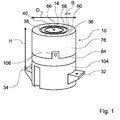
- Figures 1 and 2 show a power supply device which is integrated in a kitchen plate 30.
- a protruding from the kitchen plate 30 part of the power supply device forms a connection part 10 for attaching a kitchen appliance 12 and for connecting the kitchen appliance 12 with a household power grid.
- the connecting part 10 has a cylindrical outer surface with a vertically oriented cylinder axis, protrudes by a height of 15 mm beyond the kitchen plate 30 and has a diameter D of 60 mm.
- the fitting 10 On a circular surface, the fitting 10 has two concentric openings 58, 60 in the shape of an annular slot. Further, the connector 10 has a central, circular opening 66 which is concentric with the annular openings 58, 60. The centers of the annular shape of the openings 58, 60 and the opening 66 lie on the cylinder axis of the connecting part 10.
- a width B of the openings 58, 60 is about 1.5 mm and is thus significantly less than one-tenth of the diameter D of the connecting part 10th
- An outer diameter of the outer opening 60 is 40 mm, and an outer diameter of the smaller opening 58 is 25 mm.
- the inner diameter of the annular openings 58, 60 are smaller by 3 mm than the outer diameter.
- a housing of the connection part 10 consists of an upper housing part 76, in which the openings 58, 60, 66 are introduced, from a second housing part 84, which forms an intermediate floor, and a lower shell 104.
- the lower housing part 84 has three evenly over a Circumferentially distributed fastening tabs 106 which engage axially during assembly in corresponding recesses on the upper housing part 84 and each having a hole for a screw, by means of which the housing parts 76, 84 are screwed together radially.
- the lower shell 104 is screwed during assembly with the second housing part 84.
- connection part 10 On the lower shell 104, two opposing, designed as in installation position horizontally outwardly projecting paragraphs fasteners 32, 34 are formed, each having a hole for receiving a screw 108, 108 ', by means of the power supply device screwed to the kitchen plate 30 can be.
- An axial distance H between a contact surface of the fastening means 32, 34 and the circular top of the connection part 10 is 60 mm, so that the connection part 10 in the mounted state in the kitchen plate 30 with a standard thickness of 45 mm by 15 mm above the surface of the kitchen plate 30th protrudes.
- the annular openings 58, 66 are closed in the closed configuration shown in FIG. 1 without fitted kitchen appliance 12 by precisely fitting, likewise annular cover elements 36, 38.
- the circular opening 66 is closed by a precisely fitting, pin-shaped cover member 40.
- the upper edges of the cover members 36-40 terminate flush with the circular surface of the fitting 10.
- the cover elements 36-40 are part of a cover device 14 of the power supply device and are each independently deflectable against a spring force in the axial direction downwards or in the direction of the kitchen plate 30.
- the openings 58, 60, 66 widen inwards in the axial direction, so that in each case an undercut 56 - 56 '"is formed, which is interrupted only by narrow, axially extending guide ribs 110, 112.
- the inner sides of the guide ribs 110, 112 form Guide surfaces 52, 54 for guiding the cover members 36, 38 in the axial direction, thereby securely blocking the case 76 with the cover members 36 - 40.
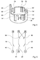
- the cover elements 36, 38 are generally cylindrical-jacket-shaped and have at a lower, the openings 58, 60 facing away from a plurality of slot-shaped recesses, each extending axially ( Figure 4).
- a first type of recesses separates three at one end to the corresponding cover member 36, 38 integrally formed locking tongues 70, 70 'of a jacket of the cover 36, 38, so that the locking tongues 70, 70' can deflect relative to the jacket in the radial direction.
- each of the locking tongues 70, 70 'on a locking lug 72 At a free end, each of the locking tongues 70, 70 'on a locking lug 72.
- the latching lugs 72 of the larger cover element 38 shown in FIG. 1 point radially inward, while the latching lugs (not illustrated here) of the smaller cover element 36 point radially outward.
- the latching tongues 70, 70 ' are formed on the cover element 38 in layers which are different by 120 ° in each case.
- Three further recesses 74-74 are also distributed at intervals of 120 ° about the circumference of the cover member 38 and serve to guide the cover member 38 in the axial direction when deflecting from the closed configuration and for fixing a rotational position of the cover member 38 relative to a housing part 76th of the connecting part 10, in which also the openings 58, 60, 66 are arranged
- the housing part 76 has three ribs 78, 78 'which extend in the radial direction and are arranged at intervals of 120 °, which in the assembled state of the power supply device into the recesses 74 - 74 "intervene.
- a width of the ribs 78, 78 ' is equal to the width of the recesses 74-74 "except for a mounting clearance and is about 3 mm.
- Three further recesses 80-80 are likewise distributed at intervals of 120 ° over the circumference of the cover element 38 and serve to hold in each case a spiral spring 82 which is supported on a second housing part 84 in the axial direction prevent, are at the bottom of the recesses 80 - 80 "and arranged on the housing part 84 each centering, which engage from both sides in the coil spring 82.
- the cover element 36 has recesses and latching tongues which are analogous to the recesses 74-74 ", 80-80" and latching tongues 70, 70 'of the illustrated cover element 38.
- the coil springs 82 bias the cover members 36, 38 upward in the axial direction.
- the locking lugs 72, 72 'come to corresponding, on the housing part 76 and the guide ribs 110, 112 integrally formed locking lugs to the system and so support the spring force of the coil springs 82 on the housing part 76 from.
- the cover elements 36, 38 are inserted axially from above into the openings 58, 60.
- the latching tongues 70-70 "deform radially inwards until the latching lugs 72, 72' engage and a latching connection is produced between the cover elements 36, 38 and the housing part 76 ,
- the pin-shaped cover member 40 is also loaded by a coil spring 82 'and can be moved against the spring force of the coil spring 82' down.
- a collar 86 is formed to support the coil spring 82 'and as a stop up to the pin-shaped cover member 40.
- the cover elements 36, 38 each have a in the axial direction through openings in the housing part 84 in a lower portion of the power supply device extending into switching tongue 88, 90, the free end has a circumferentially inclined, inclined by about 45 ° surface 92, 102 ,
- two as micro switch 94, 96 formed switching elements are arranged, each having a housing 118, 120, two contacts and a displaceable in the installed state in the circumferential direction switching knob 98, 100.
- the switching tongues 88, 90 lie with the inclined surfaces 92, 102 on the switch buttons 98, 100, so that the spring-loaded buttons 98, 100 are horizontally displaced in the installed position in the housing 118, 120 of the respective microswitch 94, 96 and there a make conductive connection between the contacts of the micro-switches 94, 96.
- the microswitches 94, 96 together form a switching device 114.
- the housing part 84 also three band-shaped contact elements 18-22 are poured, which are supported in the closed configuration in the radial direction with a grinder respectively on the side surfaces of the cover 36-40 and the open at cover 14 by their spring force into the respective opening 58th , 60, 66 are pushed into it.
- the free ends of the contact elements 18-22 have a distance 48 of 8 mm to the circular surface of the housing part 76 or of the connection part 10.
- the kitchen utensil 12 shown in detail in Figure 2 has a plug-in element 16 for entering a plug connection with the connection part 10, the essential components of which are two annular, concentric contact elements 44, 46 with cylinder jacket-shaped inner and outer surfaces and a pin-shaped contact element 42 with a round cross-section ,
- the dimensions of the contact elements 42 - 46 correspond to the dimensions of the openings 58, 60, 66, so that the contact elements 42 - 46 for attaching the kitchen appliance 12 to the connector 10 in the openings 58, 60, 66 engage and so that during a Aufsteckterrorism the cover elements 36 - 40 are moved in the axial direction into the interior of the connection part 10.
- the contact elements 18-22 contact the contact elements 42-46 and enclose three conductor plates 24-28 which pass through the kitchen plate 30 and are formed by the contact elements 18-22 and the contact elements 42 46.
- FIG. 3 ).
- the kitchen appliance 12 has a circular base portion 62, with which it is supported directly on the kitchen plate 30 in a plugged onto the connector part 10 state, so that the kitchen plate 30 and not the connector 10 carries a major part of a weight of the kitchen appliance 12.
- the base region 62 covers the connection part 10.
- the kitchen plate 30 therefore assumes the function of a base for the kitchen appliance 12.
- the base region 62 of the kitchen appliance 12 is fastened directly to a housing 64 of the kitchen appliance 12.
- the contact element 22 When installed, the contact element 22 is connected via the micro switch 94 to a negative pole of the household power network, the contact element 20 is connected via the switched microswitch 96 to a positive pole of the household power network, and the contact element 18 is directly connected to a neutral conductor of the household power network ( Figure 4).
- the contact element 18 therefore closes a protective conductor contact 116, namely in a Aufsteckvorgang the kitchen appliance 12 in advance, d. H. in front of the contact elements 20, 22, and when pulling off the kitchen appliance 12 lagging.
- the person skilled in the art can switch a potentiometer and / or a switching element 124 between the power supply device and a main part of the household power supply network at will.
- a voltage only reaches the contact element 20 when the cover element 36 covering the contact element 22 is deflected, and the contact element 22 is only connected to the household power grid when the cover element 38 covers the contact element 20 is.
- a circuit comprising the kitchen appliance 12 is closed only when both cover elements 36, 38 are simultaneously and far enough deflected from their closed configuration.
- the mechanical connection through the tabs 88, 90 is shown in Figure 4 by dashed arrows. Can therefore be connected via the cover 38, the covered by the cover 36 contact element 20, and The cover element 36 covers the contact element 22 covered by the cover element 38.
- the closing of the micro-switch 94, 96 takes place when plugging the kitchen appliance 12 only after a displacement of the cover 36 - 40, which is longer than a displacement, in which the contact elements 18 - 22 of the kitchen appliance 12 and the contact elements 42 - 46 of the connecting part 10th touch.
- a gas discharge between the kitchen appliance 12 and the connection part 10 when plugging or unplugging the kitchen appliance 12 can be avoided.
- the contact elements 42 - 46 are initially separated analogously from the domestic power grid and only then from the contact elements 18 - 22 of the kitchen appliance 12.
- a tubular drainage means 50 is formed, the liquid dripping into the power supply device on the microswitches 94, 96 passes.
- a hole for passing a connection cable 122 connected to the house power network is arranged. The hole is large enough to allow dripping of the liquid.
- FIG. 5 shows the connection part 10 in an installed state in an oblique view.
- a switching element 124 is arranged, by means of which an operator can activate and deactivate the power supply device. Further, the operator may determine a voltage applied to the contact elements 20, 22.
- Figures 7 and 8 show various built-in power supply devices of the type shown in Figures 1-5. Analogous features are provided with like reference numerals. For a description of the connecting parts 10, 10 ', reference is made to the description of Figures 1-6.
- FIG. 7 shows a modular hob 126 with a first module which comprises a kitchen plate 30 with two integrated connection parts 10, 10 '. Further, the hob 126 includes a glass ceramic hob 128 and a two-flame gas hob 130. A common control panel 132, both the connecting parts 10, 10 'and the glass ceramic hob 128 and the gas hob 130 are actuated.
- FIG. 8 shows a built-in device with two connection parts 10, 10 'and with a control device 134 with two switching buttons 136, 138 which are each assigned to one of the connection parts 10, 10'.
Landscapes
- Connector Housings Or Holding Contact Members (AREA)
- Direct Current Feeding And Distribution (AREA)
Abstract
Description
- Die Erfindung geht aus von einer Stromversorgungsvorrichtung mit einem Anschlussteil zum Aufstecken eines Küchengeräts nach dem Oberbegriff des Anspruchs 1.
- Aus der DE 37 39 318 A1 ist eine Stromversorgungsvorrichtung mit einem Anschlussteil zum Aufstecken eines Küchengeräts bekannt. Die Stromversorgungsvorrichtung umfasst mehrere Kontaktelemente zum Kontaktieren des Küchengeräts bzw. korrespondierender Kontaktelemente desselben. Ferner weist die Stromversorgungsvorrichtung eine Schaltvorrichtung zum Verbinden der Kontaktelemente mit einem Stromnetz auf, so dass durch die Schaltvorrichtung eine leitende Verbindung zwischen den Kontaktelementen und dem Stromnetz selbsttätig unterbrochen wird, wenn ein Bediener das Küchengerät von dem Anschlussteil abnimmt. Dadurch kann vermieden werden, dass bei abgenommenem Küchengerät eine Spannung auf den Kontaktelementen liegt.
- Die Aufgabe der Erfindung besteht insbesondere darin, eine Betriebssicherheit einer gattungsgemäßen Stromversorgungsvorrichtung bei abgenommenem Küchengerät zu erhöhen.
- Die Aufgabe wird erfindungsgemäß durch die Merkmale des Patentanspruchs 1 gelöst, während vorteilhafte Ausgestaltungen und Weiterbildungen der Erfindung den Unteransprüchen entnommen werden können.
- Die Erfindung geht aus von einer Stromversorgungsvorrichtung mit einem Anschlussteil zum Aufstecken eines Küchengeräts mit einem Kontaktelement zum Kontaktieren des Küchengeräts und mit einer Schaltvorrichtung zum Verbinden des Kontaktelements mit einem Stromnetz.
- Es wird vorgeschlagen, dass die Schaltvorrichtung zumindest zwei unabhängig voneinander betätigbare Schaltelemente umfasst. Dadurch kann ein versehentliches Auslösen der Schaltvorrichtung und damit ein unbeabsichtigter und gefahrenträchtiger Kontakt des Kontaktelements mit dem Stromnetz vermieden werden, und die Betriebssicherheit der Stromversorgungsvorrichtung kann verbessert werden. Zudem kann vermieden werden, dass es bereits durch eine Fehlfunktion eines einzigen Schaltelements, beispielsweise durch ein Verkleben, zu einer Gefährdung des Bedieners kommen kann. Es ist eine Stromversorgungsvorrichtung erreichbar, die feststehend in eine Einbauküche integrierbar ist und die auch dann eine hinreichende Betriebssicherheit bietet, wenn sie vorwiegend freiliegend, d. h. ohne aufgestecktes Küchengerät, ist.
- Die Schaltvorrichtung kann sowohl zur unmittelbaren als auch zur mittelbaren Verbindung des Kontaktelements mit einem Stromnetz vorgesehen sein. Die Verbindung kann über ein Stromversorgungskabel mit einem Steckelement erfolgen. Dann kann das Anschlussteil als mobile Basisstation für ein kabelloses Küchengerät einsetzbar sein, beispielsweise als Sockeleinheit für einen kabellosen Wasserkocher. Ferner kann das Anschlussteil zur Integration in eine Einbauküche vorgesehen sein. Dann kann die Schaltvorrichtung zur unmittelbaren Verbindung mit einem Haushaltsstromnetz, d. h. mit einem fest installierten Leitungssystem, oder zur mittelbaren Verbindung mit dem Haushaltsstromnetz über eine Steuereinheit ausgelegt sein. Unter "vorgesehen" soll in diesem Zusammenhang auch "ausgelegt" und "ausgestattet" verstanden werden.
- Die erfindungsgemäße Stromversorgungsvorrichtung ist vorteilhaft für eine Vielzahl von verschiedenen Küchengeräten nutzbar und bildet eine universelle Schnittstelle zum Stromnetz. Beispielsweise können Wasserkocher, Kochtöpfe mit Ohm'schen Heizwendeln, elektrische Bratpfannen, Woks, Toaster, Kaffeeautomaten, Mixer oder andere, dem Fachmann als sinnvoll erscheinende Küchengeräte auf das Anschlussteil aufgesteckt werden. Besonders vorteilhaft kann die Stromversorgungsvorrichtung zur universellen Nutzung im Zusammenhang mit einer Vielzahl von Küchengeräten mit entsprechendem Steckelement geeignet sein.
- In einer Weiterbildung der Erfindung wird vorgeschlagen, dass die Stromversorgungsvorrichtung wenigstens eine federbelastete Abdeckvorrichtung umfasst, die dazu vorgesehen ist, von einem korrespondierenden Steckelement des Küchengeräts aus einer Abdeckstellung in eine offene Stellung ausgelenkt zu sein und in der offenen Stellung das Schaltelement zu schließen. Dadurch kann ein Eindringen von Küchenflüssigkeiten und Schmutz in die Stromversorgungsvorrichtung insbesondere dann vermieden werden, wenn das Anschlusselement nicht von einem aufgesteckten Küchengerät bedeckt ist. Die Betriebssicherheit kann weiter erhöht werden, da Kurzschlüsse durch eingedrungene Verunreinigungen vermieden werden können.
- Eine weitere Verbesserung der Betriebssicherheit kann erreicht werden, wenn die Abdeckvorrichtung zumindest zwei unabhängig voneinander auslenkbare, federbelastete Abdeckelemente umfasst, die zum Schalten jeweils eines Schaltelements vorgesehen sind. Trotz eines Verklebens und/oder eines Verklemmens eines der Abdeckelemente kann dadurch erreicht werden, dass ein weiterer Teil der Abdeckvorrichtung funktionstüchtig bleibt. Dabei kann eine vollständige Integration der Abdeckfunktion und der Schaltfunktion der Abdeckvorrichtung erreicht werden, wenn jeweils ein Abdeckelement zum Schalten eines der Schaltelemente vorgesehen ist.
- Ist wenigstens ein erstes Abdeckelement zum Beschalten eines Kontaktelements vorgesehen, das von einem zweiten Abdeckelement bedeckt ist, kann vermieden werden, dass durch das Bewegen des ersten Abdeckelements allein ein unter Spannung stehendes Kontaktelement freigelegt werden kann bzw. ein freigelegtes Kontaktelement unter Spannung gesetzt werden kann. Als "Beschalten" soll in diesem Zusammenhang das Verbinden des Kontaktelements mit den Stromnetz verstanden werden.
- Eine weiter erhöhte Betriebssicherheit ist erreichbar, wenn beide Abdeckelemente zum Beschalten des von dem jeweils anderen Abdeckelement bedeckten Kontaktelements vorgesehen sind.
- Sind die Schaltelemente zu einer logischen UND-Schaltung verknüpft oder sind die Schaltelemente zwischen einer Phase des Stromnetzes und einem Kontaktelement in Reihe geschaltet, kann eine doppelte Absicherung erreicht werden, und eine Gefährdung durch eine versehentliche Betätigung eines der Schaltelemente kann vermieden werden. Die UND-Verknüpfung kann beispielsweise durch eine Reihenschaltung der Schaltelemente im Stromkreis erreicht werden, wobei ein Verbraucher des Küchengeräts von den Schaltelementen eingeschlossen werden kann. In einer anderen Ausgestaltung der Erfindung können beide Schaltelemente vor einem Kontaktelement des Anschlussteils in Reihe geschaltet sein. Dadurch kann insbesondere dann ein Sicherheitsgewinn erreicht werden, wenn das Kontaktelement zum Herstellen eines Kontakts mit einer Phase des Stromnetzes vorgesehen ist.
- Eine Funkenbildung beim Herstellen des Kontakts zwischen dem Kontaktelement und dem Küchengerät kann vermieden werden, wenn das Schaltelement nur bei geschlossenem Kontakt des Kontaktelements mit einem korrespondierenden Kontaktelement des Steckelements betätigbar ist.
- Ein Eindringen einer herabtropfenden Flüssigkeit in ein Gehäuse eines der Schaltelemente kann vermieden werden, wenn wenigstens eines der Schaltelemente ein Gehäuse mit einem in Einbaulage horizontal verschiebbaren Schaltknopf umfasst.
- Ein Feuchtwerden des Schaltmittels kann zudem verhindert werden, wenn die Stromversorgungsvorrichtung zumindest ein Drainagemittel zum Trockenlegen der Schaltvorrichtung aufweist.
- Weitere Vorteile ergeben sich aus der folgenden Zeichnungsbeschreibung. In der Zeichnung sind Ausführungsbeispiele der Erfindung dargestellt. Die Zeichnung, die Beschreibung und die Ansprüche enthalten zahlreiche Merkmale in Kombination. Der Fachmann wird die Merkmale zweckmäßigerweise auch einzeln betrachten und zu sinnvollen weiteren Kombinationen zusammenfassen.
- Es zeigen:
- Fig. 1
- eine in eine Küchenplatte integrierbare Stromversorgungsvorrichtung zum Aufstecken eines Küchengeräts,
- Fig. 2
- die Stromversorgungsvorrichtung und einen Ausschnitt eines Küchengeräts in einem Vertikalschnitt,
- Fig. 3
- die Stromversorgungsvorrichtung aus Figur 2 mit einem aufgesteckten Küchengerät,
- Fig. 4
- ein Abdeckelement der Stromversorgungsvorrichtung aus den Figuren 1 - 3,
- Fig. 5
- ein Schaltbild der Stromversorgungsvorrichtung aus den Figuren 1 -4,
- Fig. 6
- eine Küchenplatte mit einer integrierten Stromversorgungsvorrichtung,
- Fig. 7
- eine in ein modulares Kochfeld integrierte Küchenplatte mit zwei integrierten Stromversorgungsvorrichtungen und
- Fig. 8
- ein Einbaugerät mit einer Küchenplatte mit zwei integrierten Stromversorgungsvorrichtungen.
- Die Figuren 1 und 2 zeigen eine Stromversorgungsvorrichtung, die in eine Küchenplatte 30 integriert ist. Ein aus der Küchenplatte 30 herausragender Teil der Stromversorgungsvorrichtung bildet ein Anschlussteil 10 zum Aufstecken eines Küchengeräts 12 und zum Verbinden des Küchengeräts 12 mit einem Haushaltsstromnetz. Das Anschlussteil 10 hat eine zylinderförmige Außenfläche mit einer vertikal ausgerichteten Zylinderachse, ragt um eine Höhe von 15 mm über die Küchenplatte 30 hinaus und weist einen Durchmesser D von 60 mm auf.
- Auf einer kreisförmigen Oberfläche weist das Anschlussteil 10 zwei konzentrische Öffnungen 58, 60 von der Form eines ringförmigen Schlitzes auf. Ferner weist das Anschlussteil 10 eine mittige, kreisförmige Öffnung 66 auf, die zu den ringförmigen Öffnungen 58, 60 konzentrisch ist. Die Zentren der Ringform der Öffnungen 58, 60 und der Öffnung 66 liegen auf der Zylinderachse des Anschlussteils 10. Eine Breite B der Öffnungen 58, 60 beträgt etwa 1,5 mm und beträgt damit deutlich weniger als ein Zehntel des Durchmessers D des Anschlussteils 10. Ein Außendurchmesser der äußeren Öffnung 60 beträgt 40 mm und ein Außendurchmesser der kleineren Öffnung 58 beträgt 25 mm. Die Innendurchmesser der ringförmigen Öffnungen 58, 60 sind um jeweils 3 mm kleiner als die Außendurchmesser.
- Ein Gehäuse des Anschlussteils 10 besteht aus einem oberen Gehäuseteil 76, in dem die Öffnungen 58, 60, 66 eingebracht sind, aus einem zweiten Gehäuseteil 84, das einen Zwischenboden bildet, und aus einer Unterschale 104. Das untere Gehäuseteil 84 weist drei gleichmäßig über einen Umfang verteilte Befestigungslaschen 106 auf, die bei der Montage axial in korrespondierende Ausnehmungen am oberen Gehäuseteil 84 eingreifen und die jeweils ein Loch für eine Schraube aufweisen, mittels der die Gehäuseteile 76, 84 radial miteinander verschraubt werden. Die Unterschale 104 wird bei der Montage mit dem zweiten Gehäuseteil 84 verschraubt. An der Unterschale 104 sind zwei sich gegenüberliegende, als in Einbaulage horizontal nach außen ragende Absätze ausgebildete Befestigungsmittel 32, 34 angeformt, die jeweils ein Loch zur Aufnahme einer Schraube 108, 108' aufweisen, mittels der die Stromversorgungsvorrichtung mit der Küchenplatte 30 verschraubt werden kann. Ein axialer Abstand H zwischen einer Anlagefläche der Befestigungsmittel 32, 34 und der kreisförmigen Oberseite des Anschlussteils 10 beträgt 60 mm, so dass das Anschlussteil 10 im montierten Zustand in der Küchenplatte 30 mit einer Normdicke von 45 mm um 15 mm über die Oberfläche der Küchenplatte 30 hinausragt.
- Die ringförmigen Öffnungen 58, 66, sind in der in Figur 1 dargestellten geschlossenen Konfiguration ohne aufgestecktes Küchengerät 12 von passgenauen, ebenfalls ringförmigen Abdeckelementen 36, 38 verschlossen. Die kreisförmige Öffnung 66 ist von einem passgenauen, stiftförmigen Abdeckelement 40 verschlossen. In der dargestellten, geschlossenen Konfiguration schließen die oberen Ränder der Abdeckelemente 36 - 40 bündig mit der kreisförmigen Oberfläche des Anschlussteils 10 ab. Die Abdeckelemente 36 - 40 sind Teil einer Abdeckvorrichtung 14 der Stromversorgungsvorrichtung und sind jeweils unabhängig voneinander gegen eine Federkraft in axialer Richtung nach unten bzw. in Richtung der Küchenplatte 30 auslenkbar.
- Die Öffnungen 58, 60, 66 weiten sich in axialer Richtung nach innen auf, so dass jeweils eine Hinterschneidung 56 - 56'" entsteht, die nur durch schmale, axial verlaufende Führungsrippen 110, 112 unterbrochen wird. Die Innenseiten der Führungsrippen 110, 112 bilden Führungsflächen 52, 54 zum Führen der Abdeckelemente 36, 38 in der axialen Richtung. Dadurch kann ein Verkleben des Gehäuseteils 76 mit den Abdeckelementen 36 - 40 sicher vermieden werden.
- Die Abdeckelemente 36, 38 sind im Großen und Ganzen zylindermantelförmig ausgebildet und weisen an einem unteren, den Öffnungen 58, 60 abgewandten Rand mehrere schlitzförmige Ausnehmungen auf, die sich jeweils axial erstrecken (Figur 4). Ein erster Typ von Ausnehmungen trennt drei an einem Ende an das entsprechende Abdeckelement 36, 38 angeformte Rastzungen 70, 70' von einem Mantel des Abdeckelements 36, 38, so dass sich die Rastzungen 70, 70' relativ zum Mantel in radialer Richtung auslenken lassen. An einem freien Ende weist jede der Rastzungen 70, 70' eine Rastnase 72 auf. Die Rastnasen 72 des in Figur 1 dargestellten, größeren Abdeckelements 38 weisen radial nach innen, während die hier nicht dargestellten Rastnasen des kleineren Abdeckelements 36 radial nach außen weisen. Die Rastzungen 70, 70' sind in jeweils um 120° verschiedenen Lagen an das Abdeckelement 38 angeformt.
- Drei weitere Ausnehmungen 74 - 74" sind ebenfalls mit Abständen von 120° über den Umfang des Abdeckelements 38 verteilt und dienen zum Führen des Abdeckelements 38 in axialer Richtung beim Auslenken aus der geschlossenen Konfiguration und zum Fixieren einer Drehlage des Abdeckelements 38 relativ zu einem Gehäuseteil 76 des Anschlussteils 10, in dem auch die Öffnungen 58, 60, 66 angeordnet sind. Das Gehäuseteil 76 weist drei sich in radialer Richtung erstreckende und im Abstand von 120° angeordnete Rippen 78, 78' auf, die im zusammengebauten Zustand der Stromversorgungsvorrichtung in die Ausnehmungen 74 - 74" eingreifen. Eine Breite der Rippen 78, 78' ist bis auf ein Montagespiel gleich der Breite der Ausnehmungen 74 - 74" und beträgt etwa 3 mm.
- Drei weitere Ausnehmungen 80 - 80" sind ebenfalls mit Abständen von 120° über den Umfang des Abdeckelements 38 verteilt und dienen zum Halten von jeweils einer Spiralfeder 82, die sich an einem zweiten Gehäuseteil 84 in axialer Richtung abstützt. Um ein Abrutschen der Spiralfeder 82 zu verhindern, sind am Grund der Ausnehmungen 80 - 80" und am Gehäuseteil 84 jeweils Zentrierelemente angeordnet, die von beiden Seiten in die Spiralfeder 82 eingreifen.
- Das Abdeckelement 36 weist Ausnehmungen und Rastzungen auf, die zu den Ausnehmungen 74 - 74", 80 - 80" und Rastzungen 70, 70' des dargestellten Abdeckelements 38 analog sind.
- In der geschlossenen Konfiguration belasten die Spiralfedern 82 die Abdeckelemente 36, 38 in axialer Richtung nach oben. Dabei kommen die Rastnasen 72, 72` an korrespondierenden, an das Gehäuseteil 76 bzw. an die Führungsrippen 110, 112 angeformten Rastnasen zur Anlage und stützen so die Federkraft der Spiralfedern 82 an dem Gehäuseteil 76 ab. Zur Montage werden die Abdeckelemente 36, 38 axial von oben in die Öffnungen 58, 60 eingeschoben. Kommen die Rastnasen 72, 72' mit den korrespondierenden Rastnasen in Kontakt, so deformieren sich die Rastzungen 70 - 70" radial nach innen, bis die Rastnasen 72, 72' einrasten und eine Rastverbindung zwischen den Abdeckelementen 36, 38 und dem Gehäuseteil 76 hergestellt ist.
- Das stiftförmige Abdeckelement 40 ist ebenfalls durch eine Spiralfeder 82' belastet und lässt sich gegen die Federkraft der Spiralfeder 82' nach unten verschieben. Zum Abstützen der Spiralfeder 82' und als Anschlag nach oben ist an das stiftförmige Abdeckelement 40 ein Kragen 86 angeformt.
- Wird eine in axialer Richtung in Einbaulage nach unten gerichtete Kraft auf das Abdeckelement 36 ausgeübt, so wird dieses entgegen der Federkraft der Spiralfedern 82 in das Innere des Gehäuseteils 76 verschoben, bis der Grund der Ausnehmungen 74 - 74" an den Rippen 78 - 78" anstößt. Analoges gilt für das Abdeckelement 38.
- Die Abdeckelemente 36, 38 weisen jeweils eine sich in axialer Richtung durch Öffnungen im Gehäuseteil 84 in einen unteren Bereich der Stromversorgungsvorrichtung hinein erstreckende Schaltzunge 88, 90 auf, deren freies Ende eine in Umfangsrichtung schräg verlaufende, um etwa 45° geneigte Fläche 92, 102 aufweist. Im unteren Bereich sind am Gehäuseteil 84 zwei als Mikroschalter 94, 96 ausgebildete Schaltelemente angeordnet, die jeweils ein Gehäuse 118, 120, zwei Kontakte und einen im eingebauten Zustand in Umfangsrichtung verschiebbaren Schaltknopf 98, 100 aufweisen. Die Schaltzungen 88, 90 liegen mit den geneigten Flächen 92, 102 an den Schaltknöpfen 98, 100 an, so dass die federbelasteten Schaltknöpfe 98, 100 in Einbaulage horizontal in das Gehäuse 118, 120 des jeweiligen Mikroschalters 94, 96 hinein verschoben werden und dort eine leitende Verbindung zwischen den Kontakten der Mikroschalter 94, 96 herstellen. Die Mikroschalter 94, 96 bilden zusammen eine Schaltvorrichtung 114.
- In das Gehäuseteil 84 sind zudem drei bandförmige Kontaktelemente 18-22 eingegossen, die in der geschlossenen Konfiguration in radialer Richtung mit einem Schleifer jeweils an den Seitenflächen der Abdeckelemente 36 - 40 abgestützt sind und die bei geöffneter Abdeckvorrichtung 14 durch ihre Federkraft in die jeweilige Öffnung 58, 60, 66 hineingedrängt sind.
- Die freien Enden der Kontaktelemente 18 - 22 weisen einen Abstand 48 von 8 mm zu der kreisförmigen Oberfläche des Gehäuseteils 76 bzw. des Anschlussteils 10 auf.
- Das in Figur 2 in einem Ausschnitt dargestellte Küchengerät 12 weist ein Steckelement 16 zum Eingehen einer Steckverbindung mit dem Anschlussteil 10 auf, dessen wesentliche Bestandteile zwei ringförmige, konzentrische Kontaktelemente 44, 46 mit zylindermantelförmigen Innen- und Außenflächen und ein stiftförmiges Kontaktelement 42 mit rundem Querschnitt sind. Die Abmessungen der Kontaktelemente 42 - 46 entsprechen den Abmessungen der Öffnungen 58, 60, 66, so dass die Kontaktelemente 42 - 46 zum Aufstecken des Küchengeräts 12 auf das Anschlussteil 10 in die Öffnungen 58, 60, 66 eingreifen und so dass während einer Aufsteckbewegung die Abdeckelemente 36 - 40 in axialer Richtung in das Innere des Anschlussteils 10 verschoben werden. Dabei kommen nach einem Verschiebeweg von 8 mm die Kontaktelemente 18 - 22 an die Kontaktelemente 42 - 46 zur Anlage und schließen drei, die Küchenplatte 30 durchgreifende Leiterbahnen 24 - 28, die von den Kontaktelementen 18 - 22 und den Kontaktelementen 42 - 46 gebildet sind (Figur 3).
- Das Küchengerät 12 weist einen kreisförmigen Sockelbereich 62 auf, mit dem es in einem auf das Anschlussteil 10 aufgesteckten Zustand unmittelbar auf der Küchenplatte 30 abgestützt ist, so dass die Küchenplatte 30 und nicht das Anschlussteil 10 einen Hauptteil eines Gewichts des Küchengeräts 12 trägt. Der Sockelbereich 62 überdeckt dann das Anschlussteil 10. Die Küchenplatte 30 übernimmt daher die Funktion eines Sockels für das Küchengerät 12. Der Sockelbereich 62 des Küchengeräts 12 ist unmittelbar an einem Gehäuse 64 des Küchengeräts 12 befestigt.
- Im eingebauten Zustand ist das Kontaktelement 22 über den Mikroschalter 94 mit einem Minuspol des Haushaltsstromnetzes verbunden, das Kontaktelement 20 ist über den geschalteten Mikroschalter 96 mit einem Pluspol des Haushaltstromnetzes verbunden, und das Kontaktelement 18 ist unmittelbar mit einem Nullleiter des Haushaltsstromnetzes verbunden (Figur 4). Das Kontaktelement 18 schließt daher einen Schutzleiterkontakt 116, und zwar bei einem Aufsteckvorgang des Küchengeräts 12 vorauseilend, d. h. vor den Kontaktelementen 20, 22, und bei einem Abziehen des Küchengeräts 12 nacheilend. Der Fachmann kann nach Belieben einen Potentiometer und/oder ein Schaltelement 124 zwischen die Stromversorgungsvorrichtung und einen Hauptteil des Haushaltsstromnetzes schalten.
- Durch die Verschaltung der Mikroschalter 94, 96 gelangt nur dann eine Spannung auf das Kontaktelement 20, wenn das das Kontaktelement 22 bedeckende Abdeckelement 36 ausgelenkt ist, und das Kontaktelement 22 wird nur dann mit dem Haushaltsstromnetz verbunden, wenn das das Kontaktelement 20 bedeckende Abdeckelement 38 ausgelenkt ist. Ein das Küchengerät 12 umfassender Stromkreis wird nur dann geschlossen, wenn beide Abdeckelemente 36, 38 gleichzeitig und weit genug aus ihrer geschlossenen Konfiguration ausgelenkt sind. Die mechanische Verbindung durch die Schaltzungen 88, 90 ist in Figur 4 durch gestrichelte Pfeile dargestellt. Über das Abdeckelement 38 kann daher das von dem Abdeckelement 36 bedeckte Kontaktelement 20 beschaltet werden, und über das Abdeckelement 36 kann das von dem Abdeckelement 38 bedeckte Kontaktelement 22 beschaltet werden.
- Das Schließen der Mikroschalter 94, 96 erfolgt beim Aufstecken des Küchengeräts 12 erst nach einem Verschiebeweg der Abdeckelemente 36 - 40, der länger ist als ein Verschiebeweg, bei dem sich die Kontaktelemente 18 - 22 des Küchengeräts 12 und die Kontaktelemente 42 - 46 des Anschlussteils 10 berühren. Dadurch kann eine Gasentladung zwischen dem Küchengerät 12 und dem Anschlussteil 10 beim Aufstecken oder Abziehen des Küchengeräts 12 vermieden werden. Beim Abziehen des Küchengeräts 12 werden die Kontaktelemente 42 - 46 analog zunächst vom Haushaltsstromnetz und dann erst von den Kontaktelementen 18-22 des Küchengeräts 12 getrennt.
- In dem unteren Gehäuseteil 76 ist ein röhrenförmiges Drainagemittel 50 eingeformt, das in die Stromversorgungsvorrichtung hineintropfende Flüssigkeit an den Mikroschaltern 94, 96 vorbeileitet. In einer Unterschale 104 der Stromversorgungsvorrichtung ist ein Loch zum Durchführen eines mit dem Hausstromnetz verbundenen Verbindungskabels 122 angeordnet. Das Loch ist groß genug, um ein Abtropfen der Flüssigkeit zu erlauben.
- Figur 5 zeigt das Anschlussteil 10 in einem eingebauten Zustand in einer Schrägansicht. Neben dem Anschlussteil 10 ist ein Schaltelement 124 angeordnet, durch das ein Bediener die Stromversorgungsvorrichtung aktivieren und deaktivieren kann. Ferner kann der Bediener eine an den Kontaktelementen 20, 22 anliegende Spannung bestimmen.
- Die Figuren 7 und 8 zeigen verschiedene eingebaute Stromversorgungsvorrichtungen der in den Figuren 1 - 5 dargestellten Art. Analoge Merkmale sind mit gleichen Bezugszeichen versehen. Zur Beschreibung der Anschlussteile 10, 10' wird auf die Beschreibung zu den Figuren 1 - 6 verwiesen.
- Figur 7 zeigt ein modular aufgebautes Kochfeld 126 mit einem ersten Modul, das eine Küchenplatte 30 mit zwei integrierten Anschlussteilen 10, 10' umfasst. Ferner umfasst das Kochfeld 126 eine Glaskeramikkochmulde 128 und eine zweiflammige Gaskochmulde 130. Über ein gemeinsames Bedienfeld 132 können sowohl die Anschlussteile 10, 10' als auch die Glaskeramikkochmulde 128 und die Gaskochmulde 130 betätigt werden.
- Figur 8 zeigt ein Einbaugerät mit zwei Anschlussteilen 10, 10' und mit einem Steuergerät 134 mit zwei Schaltknöpfen 136, 138, die jeweils einem der Anschlussteile 10, 10' zugeordnet sind.
-
- 10
- Anschlussteil
- 12
- Küchengerät
- 14
- Abdeckvorrichtung
- 16
- Steckelement
- 18
- Kontaktelement
- 20
- Kontaktelement
- 22
- Kontaktelement
- 24
- Leiterbahn
- 26
- Leiterbahn
- 28
- Leiterbahn
- 30
- Küchenplatte
- 32
- Befestigungsmittel
- 34
- Befestigungsmittel
- 36
- Abdeckelement
- 38
- Abdeckelement
- 40
- Abdeckelement
- 42
- Kontaktelement
- 44
- Kontaktelement
- 46
- Kontaktelement
- 48
- Abstand
- 50
- Drainagemittel
- 52
- Führungsfläche
- 54
- Führungsfläche
- 56
- Hinterschneidung
- 58
- Öffnung
- 60
- Öffnung
- 62
- Sockelbereich
- 64
- Gehäuse
- 66
- Öffnung
- 70
- Rastzunge
- 72
- Rastnase
- 74
- Ausnehmung
- 76
- Gehäuseteil
- 78
- Rippe
- 80
- Ausnehmung
- 82
- Spiralfeder
- 84
- Gehäuseteil
- 86
- Kragen
- 88
- Schaltzunge
- 90
- Schaltzunge
- 92
- Fläche
- 94
- Mikroschalter
- 96
- Mikroschalter
- 98
- Schaltknopf
- 100
- Schaltknopf
- 102
- Fläche
- 104
- Unterschale
- 106
- Befestigungslasche
- 108
- Schraube
- 110
- Führungsrippe
- 112
- Führungsrippe
- 114
- Schaltvorrichtung
- 116
- Schutzleiterkontakt
- 118
- Gehäuse
- 120
- Gehäuse
- 122
- Verbindungskabel
- 124
- Schaltelement
- 126
- Kochfeld
- 128
- Glaskeramikkochmulde
- 130
- Gaskochmulde
- 132
- Bedienfeld
- 134
- Steuergerät
- 136
- Schaltknopf
- 138
- Schaltknopf
- B
- Breite
- D
- Durchmesser
- H
- Abstand
Claims (11)
- Stromversorgungsvorrichtung mit einem Anschlussteil (10) zum Aufstecken eines Küchengeräts (12) mit einem Kontaktelement (18 - 22) zum Kontaktieren des Küchengeräts (12) und mit einer Schaltvorrichtung (114) zum Verbinden des Kontaktelements (18 - 22) mit einem Stromnetz, dadurch gekennzeichnet, dass die Schaltvorrichtung (114) zumindest zwei unabhängig voneinander betätigbare Schaltelemente (94, 96) umfasst.
- Stromversorgungsvorrichtung nach Anspruch 1, gekennzeichnet durch wenigstens eine federbelastete Abdeckvorrichtung (14), die dazu vorgesehen ist, von einem korrespondierenden Steckelement (16) des Küchengeräts (12) aus einer Abdeckstellung in eine offene Stellung ausgelenkt zu sein.
- Stromversorgungsvorrichtung nach Anspruch 2, dadurch gekennzeichnet, dass die Abdeckvorrichtung (14) zumindest zwei unabhängig voneinander auslenkbare, federbelastete Abdeckelemente (36 - 40) zum Schalten jeweils eines Schaltelements (94, 96) umfasst.
- Stromversorgungsvorrichtung nach Anspruch 3, dadurch gekennzeichnet, dass wenigstens ein erstes Abdeckelement (38, 40) zum Beschalten eines Kontaktelements (20, 22) vorgesehen ist, das von einem zweiten Abdeckelement (40, 38) bedeckt ist.
- Stromversorgungsvorrichtung nach einem der Ansprüche 3 und 4, dadurch gekennzeichnet, dass beide Abdeckelemente (38, 40) zum Beschalten des von dem jeweils anderen Abdeckelement (38, 40) bedeckten Kontaktelements (20, 22) vorgesehen sind.
- Stromversorgungsvorrichtung nach einem der vorhergehenden Ansprüche, dadurch gekennzeichnet, dass die Schaltelemente (94, 96) zu einer logischen UND-Schaltung verknüpft sind.
- Stromversorgungsvorrichtung nach einem der vorhergehenden Ansprüche, dadurch gekennzeichnet, dass wenigstens ein Schaltelement (94, 96) nur bei geschlossenem Kontakt des Kontaktelements (18, 20) mit einem korrespondierenden Kontaktelement (42, 46) des Steckelements (16) betätigbar ist.
- Stromversorgungsvorrichtung nach einem der vorhergehenden Ansprüche, dadurch gekennzeichnet, dass zumindest ein Schaltelement (94, 96) nur bei geschlossenem Schutzleiterkontakt (116) betätigbar ist.
- Stromversorgungsvorrichtung nach einem der vorhergehenden Ansprüche, dadurch gekennzeichnet, dass wenigstens eines der Schaltelemente (94, 96) ein Gehäuse (118, 120) mit einem in Einbaulage horizontal verschiebbaren Schaltknopf (98, 100) umfasst.
- Stromversorgungsvorrichtung nach einem der vorhergehenden Ansprüche, gekennzeichnet durch ein Drainagemittel (50) zum Trockenlegen der Schaltvorrichtung (114).
- Küchengerät (12) mit einem Sockelbereich (62) zum Aufstecken auf eine Stromversorgungsvorrichtung nach einem der vorhergehenden Ansprüche.
Applications Claiming Priority (1)
| Application Number | Priority Date | Filing Date | Title |
|---|---|---|---|
| DE200410063283 DE102004063283A1 (de) | 2004-12-29 | 2004-12-29 | Stromversorgungsvorrichtung mit einem Anschlussteil |
Publications (3)
| Publication Number | Publication Date |
|---|---|
| EP1676507A2 true EP1676507A2 (de) | 2006-07-05 |
| EP1676507A3 EP1676507A3 (de) | 2014-05-07 |
| EP1676507B1 EP1676507B1 (de) | 2016-07-20 |
Family
ID=36072178
Family Applications (1)
| Application Number | Title | Priority Date | Filing Date |
|---|---|---|---|
| EP05109926.5A Expired - Lifetime EP1676507B1 (de) | 2004-12-29 | 2005-10-25 | Stromversorgungsvorrichtung mit einem Anschlussteil |
Country Status (2)
| Country | Link |
|---|---|
| EP (1) | EP1676507B1 (de) |
| DE (1) | DE102004063283A1 (de) |
Cited By (4)
| Publication number | Priority date | Publication date | Assignee | Title |
|---|---|---|---|---|
| WO2012080047A1 (de) * | 2010-12-17 | 2012-06-21 | BSH Bosch und Siemens Hausgeräte GmbH | Anschlusselement, haushaltsgerät mit solchem anschlusselement und einsetzmodul |
| EP2475048A4 (de) * | 2009-09-01 | 2014-07-09 | Olympus Medical Systems Corp | Elektrischer steckverbinder und endoskop |
| EP2754375A1 (de) * | 2006-07-26 | 2014-07-16 | Otter Controls Limited | Schnurloser elektrischer Verbinder |
| EP3701846A1 (de) * | 2019-02-27 | 2020-09-02 | Vorwerk & Co. Interholding GmbH | Aufnahmevorrichtung zur aufnahme mindestens eines zubereitungsgefässes für speisen mit einer heizeinrichtung |
Families Citing this family (2)
| Publication number | Priority date | Publication date | Assignee | Title |
|---|---|---|---|---|
| GB2445787B (en) * | 2007-01-16 | 2010-03-03 | Robin William Shapero | Power or data connector for appliances |
| DE102008009354B4 (de) * | 2008-02-14 | 2011-02-24 | Bowa-Electronic Gmbh & Co. Kg | Steckverbindung für einen chirurgischen Hochfrequenzgenerator |
Citations (1)
| Publication number | Priority date | Publication date | Assignee | Title |
|---|---|---|---|---|
| DE3739318A1 (de) | 1987-11-20 | 1989-06-01 | Stephan Vandaele | Elektrokochgeraet |
Family Cites Families (9)
| Publication number | Priority date | Publication date | Assignee | Title |
|---|---|---|---|---|
| NL285681A (de) * | 1961-11-20 | 1900-01-01 | ||
| EP0268722A1 (de) * | 1986-11-21 | 1988-06-01 | ELETTRODOMUS S.p.A. | Schnurloses elektrisch beheiztes Bügeleisen |
| DE4103792A1 (de) * | 1991-02-08 | 1992-08-20 | Braun Ag | Haushaltsgeraet |
| US5277602A (en) * | 1992-11-25 | 1994-01-11 | Yi Lee M | Electrical plug and receptacle assembly |
| GB9319159D0 (en) * | 1993-09-16 | 1993-11-03 | Strix Ltd | Cordless electrical appliances and connectors therefor |
| DE19655071C2 (de) * | 1996-06-12 | 2000-12-14 | Bsh Bosch Siemens Hausgeraete | Kochmulde mit Steckkupplungsteil |
| US6310306B1 (en) * | 2000-04-03 | 2001-10-30 | John Norling | Safety wall socket assembly |
| GB2374735B (en) * | 2001-04-20 | 2003-10-08 | Kettle Solutions Ltd | Electrical connector |
| DE20306052U1 (de) * | 2003-04-15 | 2003-06-12 | Wu, Chia-Hsiung, Taipeh/T'ai-pei | Elektrische Fassung eines leitfähigen Untersatzes |
-
2004
- 2004-12-29 DE DE200410063283 patent/DE102004063283A1/de not_active Withdrawn
-
2005
- 2005-10-25 EP EP05109926.5A patent/EP1676507B1/de not_active Expired - Lifetime
Patent Citations (1)
| Publication number | Priority date | Publication date | Assignee | Title |
|---|---|---|---|---|
| DE3739318A1 (de) | 1987-11-20 | 1989-06-01 | Stephan Vandaele | Elektrokochgeraet |
Cited By (7)
| Publication number | Priority date | Publication date | Assignee | Title |
|---|---|---|---|---|
| EP2754375A1 (de) * | 2006-07-26 | 2014-07-16 | Otter Controls Limited | Schnurloser elektrischer Verbinder |
| EP2475048A4 (de) * | 2009-09-01 | 2014-07-09 | Olympus Medical Systems Corp | Elektrischer steckverbinder und endoskop |
| WO2012080047A1 (de) * | 2010-12-17 | 2012-06-21 | BSH Bosch und Siemens Hausgeräte GmbH | Anschlusselement, haushaltsgerät mit solchem anschlusselement und einsetzmodul |
| US10756470B2 (en) | 2010-12-17 | 2020-08-25 | BSH Hausgeräte GmbH | Connecting element, household appliance having such a connecting element, and insert module |
| EP3701846A1 (de) * | 2019-02-27 | 2020-09-02 | Vorwerk & Co. Interholding GmbH | Aufnahmevorrichtung zur aufnahme mindestens eines zubereitungsgefässes für speisen mit einer heizeinrichtung |
| CN111616618A (zh) * | 2019-02-27 | 2020-09-04 | 福维克控股公司 | 用于容纳带加热装置的至少一个制备容器的安置装置 |
| US11276950B2 (en) | 2019-02-27 | 2022-03-15 | Vorwerk & Co. Interholding Gmbh | Mounting device with a heating device for receiving at least one preparation vessel for food |
Also Published As
| Publication number | Publication date |
|---|---|
| EP1676507B1 (de) | 2016-07-20 |
| EP1676507A3 (de) | 2014-05-07 |
| DE102004063283A1 (de) | 2006-07-13 |
Similar Documents
| Publication | Publication Date | Title |
|---|---|---|
| DE69534828T2 (de) | Gerät zum Erhitzen einer Flüssigkeit | |
| DE69333370T3 (de) | Elektrisches schnurloses Wasserheizgerät | |
| DE202007019573U1 (de) | Schnurloser elektrischer Verbinder | |
| DE20116490U1 (de) | Elektrischer Brattopf | |
| DE69301445T2 (de) | Fritiergeräte | |
| EP1676507B1 (de) | Stromversorgungsvorrichtung mit einem Anschlussteil | |
| DE102008009142A1 (de) | Elektrische Verbindungseinrichtung | |
| EP1816659A1 (de) | Elektrisches Haushaltsgerätesystem | |
| EP2510594A1 (de) | Anschlussanordnung zum schliessen eines elektrischen kontakts | |
| EP1679474B1 (de) | Stromversorgungsvorrichtung | |
| EP1278443B1 (de) | Wasserkocher mit einstellbarer wassertemperatur | |
| EP1272081B1 (de) | Haushaltsgerät | |
| DE19830181C1 (de) | Mehrpolige elektrische Steckverbindung | |
| DE4113380A1 (de) | Kabelsteckdose | |
| DE69306676T2 (de) | Gasbrenner mit Überwachungsthermoelement | |
| DE19830579C2 (de) | Verlängerungsrohranordnung für Staubsauger | |
| DE4338470A1 (de) | Wasserkochgerät | |
| DE60215714T2 (de) | Elektrischer Verbinder | |
| DE29702211U1 (de) | Grundplatte mit Steckkontakten | |
| DE3728535A1 (de) | Herdplatte | |
| DE3739318A1 (de) | Elektrokochgeraet | |
| DE4013074A1 (de) | Einstellbares geraet, insbesondere elektrisches schalt-, steuer- oder regelgeraet | |
| DE8915662U1 (de) | Elektrokochgerät | |
| DE19655071C2 (de) | Kochmulde mit Steckkupplungsteil | |
| DE4324092C1 (de) | Elektrische Schalter-Stecker-Kombination |
Legal Events
| Date | Code | Title | Description |
|---|---|---|---|
| PUAI | Public reference made under article 153(3) epc to a published international application that has entered the european phase |
Free format text: ORIGINAL CODE: 0009012 |
|
| AK | Designated contracting states |
Kind code of ref document: A2 Designated state(s): AT BE BG CH CY CZ DE DK EE ES FI FR GB GR HU IE IS IT LI LT LU LV MC NL PL PT RO SE SI SK TR |
|
| AX | Request for extension of the european patent |
Extension state: AL BA HR MK YU |
|
| PUAL | Search report despatched |
Free format text: ORIGINAL CODE: 0009013 |
|
| AK | Designated contracting states |
Kind code of ref document: A3 Designated state(s): AT BE BG CH CY CZ DE DK EE ES FI FR GB GR HU IE IS IT LI LT LU LV MC NL PL PT RO SE SI SK TR |
|
| AX | Request for extension of the european patent |
Extension state: AL BA HR MK YU |
|
| RIC1 | Information provided on ipc code assigned before grant |
Ipc: A47J 27/62 20060101ALI20140401BHEP Ipc: A47J 27/21 20060101AFI20140401BHEP Ipc: H01R 13/703 20060101ALI20140401BHEP |
|
| 17P | Request for examination filed |
Effective date: 20141107 |
|
| RBV | Designated contracting states (corrected) |
Designated state(s): AT BE BG CH CY CZ DE DK EE ES FI FR GB GR HU IE IS IT LI LT LU LV MC NL PL PT RO SE SI SK TR |
|
| AKX | Designation fees paid |
Designated state(s): AT BE BG CH CY CZ DE DK EE ES FI FR GB GR HU IE IS IT LI LT LU LV MC NL PL PT RO SE SI SK TR |
|
| AXX | Extension fees paid |
Extension state: MK Extension state: BA Extension state: AL Extension state: YU Extension state: HR |
|
| RAP1 | Party data changed (applicant data changed or rights of an application transferred) |
Owner name: BSH HAUSGERAETE GMBH |
|
| GRAP | Despatch of communication of intention to grant a patent |
Free format text: ORIGINAL CODE: EPIDOSNIGR1 |
|
| INTG | Intention to grant announced |
Effective date: 20160216 |
|
| GRAS | Grant fee paid |
Free format text: ORIGINAL CODE: EPIDOSNIGR3 |
|
| GRAA | (expected) grant |
Free format text: ORIGINAL CODE: 0009210 |
|
| AK | Designated contracting states |
Kind code of ref document: B1 Designated state(s): AT BE BG CH CY CZ DE DK EE ES FI FR GB GR HU IE IS IT LI LT LU LV MC NL PL PT RO SE SI SK TR |
|
| REG | Reference to a national code |
Ref country code: GB Ref legal event code: FG4D Free format text: NOT ENGLISH |
|
| REG | Reference to a national code |
Ref country code: CH Ref legal event code: EP |
|
| REG | Reference to a national code |
Ref country code: IE Ref legal event code: FG4D Free format text: LANGUAGE OF EP DOCUMENT: GERMAN |
|
| REG | Reference to a national code |
Ref country code: AT Ref legal event code: REF Ref document number: 813284 Country of ref document: AT Kind code of ref document: T Effective date: 20160815 |
|
| REG | Reference to a national code |
Ref country code: DE Ref legal event code: R096 Ref document number: 502005015286 Country of ref document: DE |
|
| REG | Reference to a national code |
Ref country code: LT Ref legal event code: MG4D |
|
| REG | Reference to a national code |
Ref country code: NL Ref legal event code: MP Effective date: 20160720 |
|
| PG25 | Lapsed in a contracting state [announced via postgrant information from national office to epo] |
Ref country code: FI Free format text: LAPSE BECAUSE OF FAILURE TO SUBMIT A TRANSLATION OF THE DESCRIPTION OR TO PAY THE FEE WITHIN THE PRESCRIBED TIME-LIMIT Effective date: 20160720 Ref country code: IT Free format text: LAPSE BECAUSE OF FAILURE TO SUBMIT A TRANSLATION OF THE DESCRIPTION OR TO PAY THE FEE WITHIN THE PRESCRIBED TIME-LIMIT Effective date: 20160720 Ref country code: NL Free format text: LAPSE BECAUSE OF FAILURE TO SUBMIT A TRANSLATION OF THE DESCRIPTION OR TO PAY THE FEE WITHIN THE PRESCRIBED TIME-LIMIT Effective date: 20160720 Ref country code: IS Free format text: LAPSE BECAUSE OF FAILURE TO SUBMIT A TRANSLATION OF THE DESCRIPTION OR TO PAY THE FEE WITHIN THE PRESCRIBED TIME-LIMIT Effective date: 20161120 Ref country code: LT Free format text: LAPSE BECAUSE OF FAILURE TO SUBMIT A TRANSLATION OF THE DESCRIPTION OR TO PAY THE FEE WITHIN THE PRESCRIBED TIME-LIMIT Effective date: 20160720 |
|
| PGFP | Annual fee paid to national office [announced via postgrant information from national office to epo] |
Ref country code: DE Payment date: 20161031 Year of fee payment: 12 |
|
| PG25 | Lapsed in a contracting state [announced via postgrant information from national office to epo] |
Ref country code: SE Free format text: LAPSE BECAUSE OF FAILURE TO SUBMIT A TRANSLATION OF THE DESCRIPTION OR TO PAY THE FEE WITHIN THE PRESCRIBED TIME-LIMIT Effective date: 20160720 Ref country code: BE Free format text: LAPSE BECAUSE OF NON-PAYMENT OF DUE FEES Effective date: 20161031 Ref country code: LV Free format text: LAPSE BECAUSE OF FAILURE TO SUBMIT A TRANSLATION OF THE DESCRIPTION OR TO PAY THE FEE WITHIN THE PRESCRIBED TIME-LIMIT Effective date: 20160720 Ref country code: PL Free format text: LAPSE BECAUSE OF FAILURE TO SUBMIT A TRANSLATION OF THE DESCRIPTION OR TO PAY THE FEE WITHIN THE PRESCRIBED TIME-LIMIT Effective date: 20160720 Ref country code: ES Free format text: LAPSE BECAUSE OF FAILURE TO SUBMIT A TRANSLATION OF THE DESCRIPTION OR TO PAY THE FEE WITHIN THE PRESCRIBED TIME-LIMIT Effective date: 20160720 Ref country code: GR Free format text: LAPSE BECAUSE OF FAILURE TO SUBMIT A TRANSLATION OF THE DESCRIPTION OR TO PAY THE FEE WITHIN THE PRESCRIBED TIME-LIMIT Effective date: 20161021 Ref country code: PT Free format text: LAPSE BECAUSE OF FAILURE TO SUBMIT A TRANSLATION OF THE DESCRIPTION OR TO PAY THE FEE WITHIN THE PRESCRIBED TIME-LIMIT Effective date: 20161121 |
|
| REG | Reference to a national code |
Ref country code: DE Ref legal event code: R097 Ref document number: 502005015286 Country of ref document: DE |
|
| PG25 | Lapsed in a contracting state [announced via postgrant information from national office to epo] |
Ref country code: EE Free format text: LAPSE BECAUSE OF FAILURE TO SUBMIT A TRANSLATION OF THE DESCRIPTION OR TO PAY THE FEE WITHIN THE PRESCRIBED TIME-LIMIT Effective date: 20160720 Ref country code: RO Free format text: LAPSE BECAUSE OF FAILURE TO SUBMIT A TRANSLATION OF THE DESCRIPTION OR TO PAY THE FEE WITHIN THE PRESCRIBED TIME-LIMIT Effective date: 20160720 |
|
| PLBE | No opposition filed within time limit |
Free format text: ORIGINAL CODE: 0009261 |
|
| STAA | Information on the status of an ep patent application or granted ep patent |
Free format text: STATUS: NO OPPOSITION FILED WITHIN TIME LIMIT |
|
| PG25 | Lapsed in a contracting state [announced via postgrant information from national office to epo] |
Ref country code: BG Free format text: LAPSE BECAUSE OF FAILURE TO SUBMIT A TRANSLATION OF THE DESCRIPTION OR TO PAY THE FEE WITHIN THE PRESCRIBED TIME-LIMIT Effective date: 20161020 Ref country code: CZ Free format text: LAPSE BECAUSE OF FAILURE TO SUBMIT A TRANSLATION OF THE DESCRIPTION OR TO PAY THE FEE WITHIN THE PRESCRIBED TIME-LIMIT Effective date: 20160720 Ref country code: DK Free format text: LAPSE BECAUSE OF FAILURE TO SUBMIT A TRANSLATION OF THE DESCRIPTION OR TO PAY THE FEE WITHIN THE PRESCRIBED TIME-LIMIT Effective date: 20160720 Ref country code: SK Free format text: LAPSE BECAUSE OF FAILURE TO SUBMIT A TRANSLATION OF THE DESCRIPTION OR TO PAY THE FEE WITHIN THE PRESCRIBED TIME-LIMIT Effective date: 20160720 |
|
| REG | Reference to a national code |
Ref country code: CH Ref legal event code: PL |
|
| 26N | No opposition filed |
Effective date: 20170421 |
|
| GBPC | Gb: european patent ceased through non-payment of renewal fee |
Effective date: 20161025 |
|
| REG | Reference to a national code |
Ref country code: IE Ref legal event code: MM4A |
|
| REG | Reference to a national code |
Ref country code: FR Ref legal event code: ST Effective date: 20170630 |
|
| PG25 | Lapsed in a contracting state [announced via postgrant information from national office to epo] |
Ref country code: GB Free format text: LAPSE BECAUSE OF NON-PAYMENT OF DUE FEES Effective date: 20161025 Ref country code: FR Free format text: LAPSE BECAUSE OF NON-PAYMENT OF DUE FEES Effective date: 20161102 Ref country code: CH Free format text: LAPSE BECAUSE OF NON-PAYMENT OF DUE FEES Effective date: 20161031 Ref country code: LI Free format text: LAPSE BECAUSE OF NON-PAYMENT OF DUE FEES Effective date: 20161031 |
|
| PG25 | Lapsed in a contracting state [announced via postgrant information from national office to epo] |
Ref country code: SI Free format text: LAPSE BECAUSE OF FAILURE TO SUBMIT A TRANSLATION OF THE DESCRIPTION OR TO PAY THE FEE WITHIN THE PRESCRIBED TIME-LIMIT Effective date: 20160720 Ref country code: LU Free format text: LAPSE BECAUSE OF NON-PAYMENT OF DUE FEES Effective date: 20161025 |
|
| PG25 | Lapsed in a contracting state [announced via postgrant information from national office to epo] |
Ref country code: IE Free format text: LAPSE BECAUSE OF NON-PAYMENT OF DUE FEES Effective date: 20161025 |
|
| REG | Reference to a national code |
Ref country code: BE Ref legal event code: MM Effective date: 20161031 |
|
| REG | Reference to a national code |
Ref country code: AT Ref legal event code: MM01 Ref document number: 813284 Country of ref document: AT Kind code of ref document: T Effective date: 20161025 |
|
| PG25 | Lapsed in a contracting state [announced via postgrant information from national office to epo] |
Ref country code: AT Free format text: LAPSE BECAUSE OF NON-PAYMENT OF DUE FEES Effective date: 20161025 |
|
| REG | Reference to a national code |
Ref country code: DE Ref legal event code: R119 Ref document number: 502005015286 Country of ref document: DE |
|
| PG25 | Lapsed in a contracting state [announced via postgrant information from national office to epo] |
Ref country code: HU Free format text: LAPSE BECAUSE OF FAILURE TO SUBMIT A TRANSLATION OF THE DESCRIPTION OR TO PAY THE FEE WITHIN THE PRESCRIBED TIME-LIMIT; INVALID AB INITIO Effective date: 20051025 Ref country code: CY Free format text: LAPSE BECAUSE OF FAILURE TO SUBMIT A TRANSLATION OF THE DESCRIPTION OR TO PAY THE FEE WITHIN THE PRESCRIBED TIME-LIMIT Effective date: 20160720 |
|
| PG25 | Lapsed in a contracting state [announced via postgrant information from national office to epo] |
Ref country code: MC Free format text: LAPSE BECAUSE OF FAILURE TO SUBMIT A TRANSLATION OF THE DESCRIPTION OR TO PAY THE FEE WITHIN THE PRESCRIBED TIME-LIMIT Effective date: 20160720 Ref country code: TR Free format text: LAPSE BECAUSE OF FAILURE TO SUBMIT A TRANSLATION OF THE DESCRIPTION OR TO PAY THE FEE WITHIN THE PRESCRIBED TIME-LIMIT Effective date: 20160720 |
|
| PG25 | Lapsed in a contracting state [announced via postgrant information from national office to epo] |
Ref country code: DE Free format text: LAPSE BECAUSE OF NON-PAYMENT OF DUE FEES Effective date: 20180501 |