EP1675294B1 - Dekodierung eines CQI - Google Patents
Dekodierung eines CQI Download PDFInfo
- Publication number
- EP1675294B1 EP1675294B1 EP20050254879 EP05254879A EP1675294B1 EP 1675294 B1 EP1675294 B1 EP 1675294B1 EP 20050254879 EP20050254879 EP 20050254879 EP 05254879 A EP05254879 A EP 05254879A EP 1675294 B1 EP1675294 B1 EP 1675294B1
- Authority
- EP
- European Patent Office
- Prior art keywords
- decoding
- reliability
- communication apparatus
- cqi
- decoding result
- Prior art date
- Legal status (The legal status is an assumption and is not a legal conclusion. Google has not performed a legal analysis and makes no representation as to the accuracy of the status listed.)
- Expired - Lifetime
Links
Images





Classifications
-
- H—ELECTRICITY
- H04—ELECTRIC COMMUNICATION TECHNIQUE
- H04L—TRANSMISSION OF DIGITAL INFORMATION, e.g. TELEGRAPHIC COMMUNICATION
- H04L1/00—Arrangements for detecting or preventing errors in the information received
- H04L1/004—Arrangements for detecting or preventing errors in the information received by using forward error control
- H04L1/0045—Arrangements at the receiver end
- H04L1/0054—Maximum-likelihood or sequential decoding, e.g. Viterbi, Fano, ZJ algorithms
-
- H—ELECTRICITY
- H04—ELECTRIC COMMUNICATION TECHNIQUE
- H04L—TRANSMISSION OF DIGITAL INFORMATION, e.g. TELEGRAPHIC COMMUNICATION
- H04L1/00—Arrangements for detecting or preventing errors in the information received
- H04L1/0001—Systems modifying transmission characteristics according to link quality, e.g. power backoff
- H04L1/0009—Systems modifying transmission characteristics according to link quality, e.g. power backoff by adapting the channel coding
- H04L1/001—Systems modifying transmission characteristics according to link quality, e.g. power backoff by adapting the channel coding applied to control information
-
- H—ELECTRICITY
- H04—ELECTRIC COMMUNICATION TECHNIQUE
- H04L—TRANSMISSION OF DIGITAL INFORMATION, e.g. TELEGRAPHIC COMMUNICATION
- H04L1/00—Arrangements for detecting or preventing errors in the information received
- H04L1/0001—Systems modifying transmission characteristics according to link quality, e.g. power backoff
- H04L1/0023—Systems modifying transmission characteristics according to link quality, e.g. power backoff characterised by the signalling
- H04L1/0028—Formatting
-
- H—ELECTRICITY
- H04—ELECTRIC COMMUNICATION TECHNIQUE
- H04L—TRANSMISSION OF DIGITAL INFORMATION, e.g. TELEGRAPHIC COMMUNICATION
- H04L1/00—Arrangements for detecting or preventing errors in the information received
- H04L1/0001—Systems modifying transmission characteristics according to link quality, e.g. power backoff
- H04L1/0033—Systems modifying transmission characteristics according to link quality, e.g. power backoff arrangements specific to the transmitter
-
- H—ELECTRICITY
- H04—ELECTRIC COMMUNICATION TECHNIQUE
- H04L—TRANSMISSION OF DIGITAL INFORMATION, e.g. TELEGRAPHIC COMMUNICATION
- H04L1/00—Arrangements for detecting or preventing errors in the information received
- H04L1/0001—Systems modifying transmission characteristics according to link quality, e.g. power backoff
- H04L1/0033—Systems modifying transmission characteristics according to link quality, e.g. power backoff arrangements specific to the transmitter
- H04L1/0035—Systems modifying transmission characteristics according to link quality, e.g. power backoff arrangements specific to the transmitter evaluation of received explicit signalling
-
- H—ELECTRICITY
- H04—ELECTRIC COMMUNICATION TECHNIQUE
- H04L—TRANSMISSION OF DIGITAL INFORMATION, e.g. TELEGRAPHIC COMMUNICATION
- H04L1/00—Arrangements for detecting or preventing errors in the information received
- H04L1/0001—Systems modifying transmission characteristics according to link quality, e.g. power backoff
- H04L1/0036—Systems modifying transmission characteristics according to link quality, e.g. power backoff arrangements specific to the receiver
- H04L1/0039—Systems modifying transmission characteristics according to link quality, e.g. power backoff arrangements specific to the receiver other detection of signalling, e.g. detection of TFCI explicit signalling
-
- H—ELECTRICITY
- H04—ELECTRIC COMMUNICATION TECHNIQUE
- H04L—TRANSMISSION OF DIGITAL INFORMATION, e.g. TELEGRAPHIC COMMUNICATION
- H04L1/00—Arrangements for detecting or preventing errors in the information received
- H04L1/004—Arrangements for detecting or preventing errors in the information received by using forward error control
- H04L1/0072—Error control for data other than payload data, e.g. control data
-
- H—ELECTRICITY
- H04—ELECTRIC COMMUNICATION TECHNIQUE
- H04W—WIRELESS COMMUNICATION NETWORKS
- H04W52/00—Power management, e.g. Transmission Power Control [TPC] or power classes
- H04W52/04—Transmission power control [TPC]
Definitions
- the present invention generally relates to a correlating decoding method using a maximum likelihood (ML) detection algorithm, and more particularly, to an error correction decoding technique for improving decoding characteristics, as well as to a communication apparatus and a digital transmission system using the error correction decoding technique.
- ML maximum likelihood
- W-CDMA Wideband Code Division Multiple Access
- TFCI transport format combination indicator
- CQI channel quality indicator
- the transport format combination indicator (TFCI) is used to report a combination of transport channels multiplexed on layer 1, such that a communication node that receives data can correctly separate and decode the data of each of the transport channels.
- the channel quality indicator is used to feed the downlink transmission quality measured by a mobile terminal back to a base station, the downlink employing high speed downlink packet access (HSDPA) which is the extended standard of the W-CDMA downlink transmission.
- HSDPA high speed downlink packet access
- the base station controls the coding rate and the modulation scheme of the HS-PDSCH (high speed physical downlink shared channel) in an adaptive manner, according to the downlink channel quality.
- the Reed-Muller code is an extended orthogonal code, and can be decoded based on correlating decoding or soft-decision majority decoding.
- Correlating decoding is a decoding method using a maximum likelihood decision for selecting a code word that has the maximum correlation value with respect to the received sequence among all possible code words that can be transmitted, and is superior in decoding characteristic to simpler soft-decision majority decoding.
- the information bit sizes of the CQI and TFCI are 5 bits (32 code words) and 10 bits (1024 code words), respectively, and accordingly, the computational scale is at a realistic level.
- the transmitted information is an essential parameter affecting the system performance, it is preferred to use a correlating decoding method having superior decoding characteristics.
- FIG. 1 A conventional structure of the receiving end of a W-CDMA base station that performs CQI decoding is shown in FIG. 1 .
- An RF signal received at the receiving antenna 1 is input to the RX unit (or baseband processing unit) 2, and converted into a baseband signal through frequency conversion.
- Despreading unit 3 performs despreading on the baseband signal for each user to separate the contained physical channels, such as dedicated physical control channel (DPCCH), high speed dedicated physical control channel (HS-DPCCH) for HS-DSCH, and dedicated physical data channel (DPDCH), from the user-based code-multiplexed signal.
- the despread symbols of each physical channel are supplied to the synchronous detection unit 4, in which phase rotation generated on the channel is corrected by channel estimation using a pilot signal mapped on the DPCCH. Since the CQI is mapped on the HS-DPCCH, a decoding operation is carried out using the synchronous detection result for the HS-DPCCH.
- the HS-DPCCH synchronous-detected symbol is input to the fast Hadamard transform (FHT) unit 5 to take correlation with each of the 32 code words.
- the maximum value detection unit 6 determines a correlation value with the maximum absolute value among the 32 correlation values, and outputs the information bits corresponding to the code word of the maximum correlation as a decoded CQI value.
- TFCI can also be decoded in a similar manner because the only difference from CQI is that TFCI is mapped on a DPCCH.
- Channel estimation for a received signal is disclosed in, for example, JP 2003-115783A .
- CQI and TFCI used in a W-CDMA system are decoded using a correlation decoding method, which is a kind of maximum likelihood decoding technique, a certain level of coding gain can be obtained.
- CQI and TFCI propagate important parameters directed to the essential part of the system performance, and the influence on the system due to decoding error is quite large, as described above. Accordingly, in order to guarantee a required decoding quality, a certain type of power distribution to CQI and TFCI has to be performed through gain factor control by an upper layer. For example, when the decoding quality is low, the power level allocated to CQI or TFCI has to be increased. This may lead to increase of interference level at other nodes and increase of power consumption of the focused node (especially, a waste of battery energy in a mobile phone). Accordingly, it is an important issue to make further improvement for increasing the system capacity and reducing transmit power levels.
- JP 2003-115783A discloses improvement of the decoding characteristic (or estimation accuracy)
- this publication is not directed to improvement of the decoding characteristic of control information itself.
- This publication is based on the assumption that high decoding accuracy is already guaranteed by adding a redundancy bit to the control information. After the control information with the redundancy bit is decoded correctly, the decoded information is encoded again so as to be used as a known symbol similar to a pilot symbol.
- EP-A-1478114 discloses an error correction decoding method employing a correlation decoding technique, which method includes the steps of estimating decoding reliability of a decoding result using one or more correlation values acquired during the correlating operation, and correcting the decoding result according to the decoding reliability.
- the present invention was conceived in view of the above-described problems in the prior art, and it is an object to provide an error correction decoding method, a communication apparatus, and a digital transmission system that can allow further improvement of the correlating decoding characteristic.
- the decoding reliability may be compared with a prescribed threshold to determine whether the decoding result is valid (or invalid). For example, if the decoding reliability is at or above the threshold, the decoding result is valid, otherwise, it is determined as being invalid. If the decoding result is invalid, the most recent effective decoding result may be used in place of the invalid decoding result.
- the determination threshold is set to the optimum value so as to allow accurate determination for invalid decoding results when decoding error occurs.
- the current decoding result that is likely to be incorrect, error operations or adverse influence on the system due to the incorrect decoded values can be reduced.
- replacing the current decoded value by the previous effective decoding value is effective in improving the decoding accuracy.
- an average of the past effective decoding results may be output, in place of the current decoding result.
- an extrapolation value of the past effective decoding results may be output, in place of the current invalid decoding result.
- a communication apparatus comprising: a receiving unit configured to receive a decoding reliability from a second communication apparatus, which is in communication with the communication apparatus when the apparatus is in use, the second communication apparatus being apparatus according to the second aspect of the present invention; and a control unit configured to dynamically control a transmission parameter for an information item to be decoded such that the decoding reliability satisfies a required quality.
- a digital transmission system including a first communication apparatus and a second communication apparatus connected so as to communicate with each other, wherein the first communication apparatus comprises apparatus according to the second aspect of the present invention, the transmitting means being configured to transmit the decoding reliability to the second communication apparatus; and wherein the second communication apparatus comprises apparatus according to the third aspect of the present invention.
- the decoding reliability may be transmitted to the node being in communication with the focused communication apparatus.
- the counterpart node may control the transmission parameters, such as a coding rate or a transmit power level, in a dynamic manner such that the decoding reliability satisfies a prescribed quality.
- the minimum coding rate or transmit power level required to achieve a desired decoding reliability can be selected appropriately, and efficient data transmission and reduction of power consumption can be realized. Redundant interference affecting the surroundings can also be reduced by optimizing the transmit power level.
- the coding rate or the transmit power of the counterpart node can be adaptively controlled according to the change in transmission quality. Consequently, efficient information transmission, reduction of power consumption, and reduction of interference level affecting the surroundings can be realized.
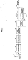
- FIG. 2 is a schematic block diagram illustrating a CQI decoding technique according to the first embodiment of the present invention.
- a radio signal received at a receiving antenna 11 is converted to a baseband signal through frequency conversion at an RX unit 12.
- a despreading unit 13 performs despreading for each user to separate the user signal into physical channels DPCCH, HS-DPCCH, and DPDCH which have been code-multiplexed for each user.
- the despread symbol of each of the separated physical channels is supplied to the synchronous detector 14, in which phase rotation having occurred in the channel is corrected by channel estimation using the pilot signal mapped on the DPCCH. Since CQI is mapped on the HS-DPCCH, CQI is to be decoded using the synchronous decoding result of the HS-DPCCH.
- the HS-DPCCH synchronous-detected symbol is input to a fast Hadamard transform (FHT) unit 15, and subjected to correlation with 32 code words.
- FHT fast Hadamard transform
- FHT fast Hadamard transform
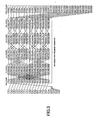
- FIG. 3 is an example of fast Hadamard transform performed by the FHT unit 15.
- the FHT unit 15 Based on the 20-symbol CQI (with symbols b 0 -b 19 ) supplied from the synchronous detector 14, sixteen sequences x 0,0 through x 0,15 are acquired.
- sixteen correlation values X 4,0 through X 4,15 are obtained by 16 th degree fast Hadamard transform.
- the operation expressed by Equation (3) is performed.
- X 4 , 0 X 4 , 1 M X 4 , 15 H 16 X 0 , 0 X 0 , 1 M X 0 , 15
- the sign-inverted 16 correlation values are obtained from the sixteen correlation values, and thus, a total of thirty two (32) correlation values y 0 -y 31 are obtained.
- the maximum correlation value y m and the second greatest correlation value y n are output as x 1 and x 2 , respectively, from the maximum value detection unit 16, as illustrated in FIG. 2 .
- ⁇ CQI is the transmission amplitude ratio of CQI to DPCCH
- N denotes the average noise level. Because ⁇ CQI , is a parameter reported from an upper layer, this parameter is known at a base station. N is acquired by an ordinary noise-level measuring process.
- S DPCCH denotes the receipt power level of DPCCH
- S CQI is the receipt power level of the CQI symbol
- S DPCCH and S CQI satisfy the following relation.
- S CQI S DPCCH ⁇ ⁇ CQI 2
- a channel quality indicator is generated as 20-symbol (20, 5) code based on the 16-symbol code word obtained from the Reed-Muller (16, 5) code and by repeating the 16 th code symbol four times (to add four symbols).
- the distribution of the correlation value with respect to a code word consistent with the transmitted CQI becomes a Gaussian distribution with an average of twenty (20) S DPCCH ⁇ CQI values and variance of twenty (20) S DPCCH *N values.
- the distribution of the correlation value with respect to a code word inconsistent with the transmitted CQI becomes a Gaussian distribution with an average of four (4) S DPCCH ⁇ CQI values and variance of twenty (20) S DPCCH * N values.
- the decoding reliability can be approximated as C ⁇ A 1 A 2 .
- the decoding reliability can be determined.
- Equation (15) can be interpreted as stating that the difference between the maximum correlation value and the second greatest correlation value is normalized to a dimensionless value and then multiplied by the receipt SNR (signal to noise ratio) of the CQI symbol.
- the decoding reliability estimated by the reliability estimator 17 is supplied as a weighting coefficient to the multiplier 18.
- decoding error for CQI may cause the following influences.
- the distribution of decoding error in correlating decoding becomes random. If the decoding result turns up to be a much greater value than the actually transmitted CQI due to decoding error, an excessively high transmission rate is to be set with respect to the actual downlink transmission quality. In this case, the mobile terminal cannot decode the data correctly, which leads to retransmission of data.
- a decoding result is corrected such that the decoded CQI value is weighted using a smaller weighting coefficient when the decoding reliability is low. This arrangement can reduce adverse influence on the system when decoding error results in a large CQI value.
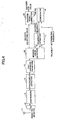
- FIG. 4 is a schematic block diagram illustrating a CQI decoding technique according to the second embodiment of the invention.
- correction for a CQI decoding result is different from that in the first embodiment, and therefore, explanation is mainly made of the difference in the correcting method.
- the decoding reliability K estimated by the reliability estimator 17 using the above-described method is input to a comparator 19, and compared with a prescribed threshold, which is a criterion of determination of the reliability.
- the comparator 19 determines that the decoding is valid (OK) when K is greater than or equal to the threshold (K ⁇ threshold), and outputs a determination of invalid (NG) when the reliability K is less than the threshold (K ⁇ threshold).
- the threshold used for the reliability determination is set to the optimum value in advance such that the decoding result is determined accurately as being invalid if decoding error has occurred.
- the output of the comparator 19 is connected to one input of a decoding result correction unit 20, which makes correction to the decoding result using one of the three methods illustrated in FIG. 5 through FIG. 7 to output a final value of decoded CQI. Examples of the decoding result correction are explained below.
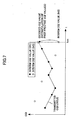
- This method is illustrated in FIG. 7 .
- the slope (change in time) is extrapolated to estimate or replace the current decoded value.
- the system performance is improved, as compared with the case in which an improper CQI without correlation with change in time is employed.
- the following capability to change in time can be improved as compared with the above-described methods (1) and (2).
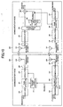
- FIG. 9 is a block diagram illustrating an example of a digital (wireless) transmission system. This system is on the presumption that at least a portion of information (I) transmitted from a second node (communication apparatus) 200 to a first node (communication apparatus) 100 is encoded using a coding scheme decodable by correlating decoding.
- the first communication apparatus 100 includes a receiver and a transmitter.
- the receiver includes a receiving antenna 101, an RX unit 102, a demodulator 103, a correlating decoder 104, a reliability estimator 105, and a multiplier 106.
- the transmitter includes an encoder 107, a frame generator 108, a modulator 109, a TX unit 110, and a transmission antenna 111.
- the receiver is similar to that of the first embodiment shown in FIG. 2 ; however, the despreader 13 and the synchronous detector 14 are replaced by the demodulator 103. Accordingly, the structure and the method of this example can be expanded to general demodulation schemes, other than CDMA.
- the fast Hadamard transform unit 15 and the maximum value detector 16 are collectively depicted as the correlating decoder 104.
- the other blocks are the same as those of the previous embodiments, and accordingly, explanation for them is omitted.
- the dashed block including the reliability estimator 105 and the multiplier 106 makes correction to the received information I according to the decoding reliability.
- This block may be replaced by the combination of the reliability estimator 17, the comparator 19 and the decoding result correcting unit 20 of the second embodiment shown in FIG. 4 .
- the data to be transmitted to the node 200 are encoded by the encoder 107.
- the frame generator 108 multiplexes/maps the coded data to radio frames.
- the decoding reliability estimated by the reliability estimator 105 is also mapped on the radio frames so as to be transmitted to the node 200.
- the data frames are modulated by the modulator 109 using a prescribed modulation scheme, subjected to frequency conversion to a radio frequency at the TX unit 110, and transmitted from the transmission antenna 111.
- the counterpart node 200 in communication with the communication apparatus 100 also includes a receiver and a transmitter.
- the receiver includes a receiving antenna 201, an RX unit 202, a demodulator 203, a reliability extraction unit 204, and a decoder 205.
- the transmitter includes an encoder 206, a frame generator 207, a modulator 208, a TX unit 209, and a transmission antenna 210.
- the blocks other than the reliability extraction unit 204 of the receiver and the encoder 206 of the transmitter are the same as those already explained above, and therefore, explanation for them is omitted.
- the reliability extraction unit 204 separates and extracts the decoding reliability mapped on a prescribed field of the radio frame, and supplies the extracted reliability to the encoder 206 of the transmitter.
- the encoder 206 controls the coding rate for information I such that the coding reliability satisfies the required quality. If the decoding reliability is at or above the required quality, the decoding reliability is sufficient, and therefore, the coding rate is reduced by one stepsize in order to increase the amount of information to be transmitted, while slightly reducing the error correction ability. If the decoding reliability is less than the required quality, the decoding reliability is insufficient, and therefore, the coding rate is increased by one stepsize so as to improve the error correction ability in exchange for decreasing the amount of information to be transmitted.
- FIG. 10 is a block diagram of another example of a digital (wireless) transmission system. This system is different from the system of FIG. 9 in that a transmit power controller 211 is added behind the frame generator 207 in the counterpart node (communication apparatus) 200.
- the transmit power controller 211 receives a data frame generated by the frame generator 207 at one input terminal, while receiving the decoding reliability extracted by the reliability extraction unit 204 at the other input terminal, and controls the transmit power level of information I mapped in the data frame such that the decoding reliability satisfies a required quality.
- the decoding reliability is at or above the required quality, the decoding reliability is sufficient, and therefore, the transmit power is reduced by one stepsize to reduce power consumption and interference level to the surroundings.
- the decoding reliability is lower than the required quality, the decoding reliability is insufficient, and therefore, the transmit power is raised by one stepsize to improve the decoding reliability.
- the transmit power is adjusted to a level required at least to maintain the decoding reliability so as to satisfy the required quality in accordance with the channel quality. Consequently, excessive power consumption and interference against the surroundings can be prevented.
Landscapes
- Engineering & Computer Science (AREA)
- Computer Networks & Wireless Communication (AREA)
- Signal Processing (AREA)
- Quality & Reliability (AREA)
- Artificial Intelligence (AREA)
- Mobile Radio Communication Systems (AREA)
- Error Detection And Correction (AREA)
- Detection And Prevention Of Errors In Transmission (AREA)
Claims (13)
- Fehlerkorrekturdecodierverfahren, unter Verwendung einer korrelierenden Decodiertechnik zum Decodieren eines Kanalqualitätsindikators, der in einem W-CDMA-System verwendet wird, mit den Schritten:Schätzen einer Decodierzuverlässigkeit K eines Decodierresultates unter Verwendung von einem oder mehreren Korrelationswerten, die bei einem korrelierenden Prozess erfasst werden; undKorrigieren des Decodierresultates gemäß der Decodierzuverlässigkeit;dadurch gekennzeichnet, dass ein Schätzwert für die Decodierzuverlässigkeit K unter Verwendung der Beziehung gefunden wird:

wobei ΔCQI das Sendeamplitudenverhältnis des Kanalqualitätsindikators zu einem dedizierten physikalischen Steuerkanal des W-CDMA-Systems ist, N der durchschnittliche Rauschpegel ist und x1 und x2 die größten bzw. zweitgrößten Korrelationswerte sind. - Verfahren nach Anspruch 1, ferner mit dem Schritt:Vergleichen der geschätzten Zuverlässigkeit K mit einem Schwellenwert.
- Verfahren nach Anspruch 1 oder 2, ferner mit dem Schritt:Ausgeben eines Produktes aus der Decodicrzuverlässigkeit und einem korrelierenden decodierten Wert als gegenwärtiges Decodierresultat.
- Verfahren nach Anspruch 2, ferner mit dem Schritt:Bestimmen, falls die Decodierzuverlässigkeit kleiner als der Schwellenwert ist, dass das Decodierresultat ungültig ist, und Ausgeben eines vorherigen gültigen Decodierresultates als gegenwärtiges Decodierresultat anstelle des ungültigen Decodierresultates.
- Verfahren nach Anspruch 2, ferner mit dem Schritt:Bestimmen, falls die Decodierzuverlässigkeit kleiner als der Schwellenwert ist, dass das Decodierresultat ungültig ist, und Ausgeben eines Durchschnittes von früheren gültigen Decodierresultaten als gegenwärtiges Decodierresultat anstelle des ungültigen Decodierresultates.
- Verfahren nach Anspruch 2, ferner mit dem Schritt:Bestimmen, falls die Decodierzuverlässigkeit kleiner als der Schwellenwert ist, dass das Decodierresultat ungültig ist, und Ausgeben einer Extrapolation von früheren gültigen Decodierresultaten.
- Kommunikationsvorrichtung, die eine korrelierende Decodiertechnik verwendet, um einen Kanalqualitätsindikator, der in einem W-CDMA-System verwendet wird, zu decodieren, mit:einem Decodierzuverlässigkeitsschätzer, der konfiguriert ist, um eine Decodierzuverlässigkeit K eines Decodierresultates unter Verwendung von einem oder mehreren Korrelationswerten zu schätzen, die bei einem korrelierenden Prozess erfasst werden; undeiner Korrektureinheit, die konfiguriert ist, um das Decodierresultat gemäß der Decodierzuverlässigkeit zu korrigieren;dadurch gekennzeichnet, dass der Decodierzuverlässigkeitsschätzer betriebsfähig ist, um den Schätzwert für die Decodierzuverlässigkeit K unter Verwendung der Beziehung zu finden:

wobei ΔCQI das Sendeamplitudenverhältnis des Kanalqualitätsindikators zu einem dedizierten physikalischen Steuerkanal des W-CDMA-Systems ist, N der durchschnittliche Rauschpegel ist und x1 und x2 die größten bzw. zweitgrößten Korrelationswerte sind. - Kommunikationsvorrichtunq nach Anspruch 7, ferner mit einem Vergleichsmittel zum Vergleichen der geschätzten Zuverlässigkeit K mit einem Schwellenwert.
- Kommunikationsvorrichtung nach Anspruch 7 oder 8, ferner mit:einem Sendemittel, das die Decodierzuverlässigkeit an einen Kommunikationsknoten sendet, der mit der Kommunikationsvorrichtung kommuniziert.
- Kommunikationsvorrichtung mit:einer Empfangseinheit, die konfiguriert ist, um eine Decodierzuverlässigkeit von einer zweiten Kommunikationsvorrichtung zu empfangen, die mit der Kommunikationsvorrichtung kommuniziert, wenn die Vorrichtung in Gebrauch ist, welche zweite Kommunikationsvorrichtung eine Vorrichtung nach Anspruch 7, 8 oder 9 ist; undeiner Steuereinheit, die konfiguriert ist, um einen Sendeparameter für ein Informationselement, das zu decodieren ist, dynamisch zu steuern, so dass die Decodierzuverlässigkeit einer geforderten Qualität entspricht.
- Kommunikationsvorrichtung nach Anspruch 10, bei der der Sendeparameter ein Parameter zum Bestimmen einer Codierrate von Daten ist, die von der Kommunikationsvorrichtung zu senden sind.
- Kommunikationsvorrichtung nach Anspruch 10, bei der der Sendeparameter ein Parameter zum Bestimmen eines Sendeleistungspegels von Daten ist, die von der Kommunikationsvorrichtung zu senden sind.
- Digitales Sendesystem mit einer ersten Kommunikationsvorrichtung und einer zweiten Kommunikationsvorrichtung, die verbunden sind, um miteinander zu kommunizieren,bei dem die erste Kommunikationsvorrichtung eine Vorrichtung nach Anspruch 9 umfasst, wobei das Sendemittel konfiguriert ist, um die Decodierzuverlässigkeit an die zweite Kommunikationsvorrichtung zu senden; undbei dem die zweite Kommunikationsvorrichtung eine Vorrichtung nach Anspruch 10 umfasst.
Applications Claiming Priority (2)
| Application Number | Priority Date | Filing Date | Title |
|---|---|---|---|
| JP2004374316 | 2004-12-24 | ||
| JP2005128702A JP4528193B2 (ja) | 2004-12-24 | 2005-04-26 | 誤り訂正復号方法、通信装置、及び、デジタル伝送システム |
Publications (2)
| Publication Number | Publication Date |
|---|---|
| EP1675294A1 EP1675294A1 (de) | 2006-06-28 |
| EP1675294B1 true EP1675294B1 (de) | 2008-07-23 |
Family
ID=35500546
Family Applications (1)
| Application Number | Title | Priority Date | Filing Date |
|---|---|---|---|
| EP20050254879 Expired - Lifetime EP1675294B1 (de) | 2004-12-24 | 2005-08-04 | Dekodierung eines CQI |
Country Status (4)
| Country | Link |
|---|---|
| US (1) | US20060140313A1 (de) |
| EP (1) | EP1675294B1 (de) |
| JP (1) | JP4528193B2 (de) |
| DE (1) | DE602005008353D1 (de) |
Cited By (1)
| Publication number | Priority date | Publication date | Assignee | Title |
|---|---|---|---|---|
| JP2006203843A (ja) * | 2004-12-24 | 2006-08-03 | Fujitsu Ltd | 誤り訂正復号方法、通信装置、及び、デジタル伝送システム |
Families Citing this family (19)
| Publication number | Priority date | Publication date | Assignee | Title |
|---|---|---|---|---|
| US8068530B2 (en) * | 2004-06-18 | 2011-11-29 | Qualcomm Incorporated | Signal acquisition in a wireless communication system |
| US7424071B2 (en) * | 2005-06-27 | 2008-09-09 | Icera Inc. | Decoder and a method for determining a decoding reliability indicator |
| KR100863791B1 (ko) * | 2005-10-12 | 2008-10-17 | 삼성전자주식회사 | 주파수분할 다중접속 방식의 통신시스템에서 패킷 데이터 제어 채널을 이용하여 채널을 추정하기 위한 송수신 장치 및 방법과 그 시스템 |
| EP1946577B1 (de) * | 2005-11-09 | 2013-01-02 | Telefonaktiebolaget LM Ericsson (publ) | Auswahl von funkbetriebsmitteln in einem funkkommunikationsnetz |
| US8738056B2 (en) * | 2006-05-22 | 2014-05-27 | Qualcomm Incorporation | Signal acquisition in a wireless communication system |
| US8929353B2 (en) | 2007-05-09 | 2015-01-06 | Qualcomm Incorporated | Preamble structure and acquisition for a wireless communication system |
| US8676209B2 (en) * | 2006-06-13 | 2014-03-18 | Qualcomm Incorporated | Handoff selection for wireless communication systems |
| EP1973253A1 (de) * | 2007-03-21 | 2008-09-24 | Nokia Siemens Networks Gmbh & Co. Kg | Verfahren und System zur Anpassung eines Modulations- und Kodierungsschemas |
| US20080285512A1 (en) * | 2007-05-01 | 2008-11-20 | Interdigital Technology Corporation | Method and apparatus for reducing modulation, coding and transport block information signaling overhead |
| FR2937760B1 (fr) | 2008-10-28 | 2016-01-01 | Thales Sa | Procede de correction d'erreurs de prediction de valeurs de signaux a evolution temporelle |
| JP5262894B2 (ja) | 2009-03-24 | 2013-08-14 | 富士通株式会社 | 無線通信システムにおける復号誤り検出方法および復号装置 |
| EP2254254B1 (de) * | 2009-05-19 | 2014-04-09 | TELEFONAKTIEBOLAGET LM ERICSSON (publ) | Verfahren und Steuereinheit zur Steuerung einer Funkempfängerschaltung |
| WO2010134196A1 (ja) | 2009-05-22 | 2010-11-25 | 富士通株式会社 | 通信システム及び情報伝送方法及びコード設定方法及び基地局及び移動局 |
| JP5371556B2 (ja) * | 2009-06-03 | 2013-12-18 | 株式会社エヌ・ティ・ティ・ドコモ | 無線通信装置及び物理制御チャネル受信方法 |
| JP5713723B2 (ja) * | 2011-02-21 | 2015-05-07 | 三菱電機株式会社 | 受信装置 |
| DE102013001740B3 (de) * | 2013-02-01 | 2014-01-09 | Eberhard Karls Universität Tübingen | Anordnung und Verfahren zur Decodierung eines Datenworts mit Hilfe eines Reed-Muller-Codes |
| US9405616B2 (en) * | 2013-11-27 | 2016-08-02 | Qualcomm Incorporated | Reliability metric for decoding hypothesis |
| US9457754B1 (en) | 2015-07-13 | 2016-10-04 | State Farm Mutual Automobile Insurance Company | Method and system for identifying vehicle collisions using sensor data |
| US10021130B2 (en) * | 2015-09-28 | 2018-07-10 | Verizon Patent And Licensing Inc. | Network state information correlation to detect anomalous conditions |
Family Cites Families (12)
| Publication number | Priority date | Publication date | Assignee | Title |
|---|---|---|---|---|
| JP3399923B2 (ja) * | 2000-11-29 | 2003-04-28 | 松下電器産業株式会社 | 通信端末装置および通信端末装置における復号化方法 |
| JP3881959B2 (ja) * | 2001-03-05 | 2007-02-14 | 三菱電機株式会社 | 伝送フォーマット判定方法 |
| JP4318412B2 (ja) * | 2001-08-08 | 2009-08-26 | 富士通株式会社 | 通信システムにおける送受信装置及び送受信方法 |
| JP2003115783A (ja) | 2001-10-05 | 2003-04-18 | Matsushita Electric Ind Co Ltd | 受信信号の伝搬路特性の推定方法およびcdma受信装置 |
| US7209712B2 (en) * | 2002-09-23 | 2007-04-24 | Qualcomm, Incorporated | Mean square estimation of channel quality measure |
| JP4035421B2 (ja) * | 2002-10-18 | 2008-01-23 | 株式会社イトーヨーギョー | 管渠の止水壁装置とこれを用いた管渠内の仮設水路装置 |
| JP3742055B2 (ja) * | 2002-11-27 | 2006-02-01 | 埼玉日本電気株式会社 | 無線基地局装置、及びそれに用いるtfci復号特性を利用する復号装置とその復号方法 |
| KR101017040B1 (ko) * | 2002-12-04 | 2011-02-23 | 인터디지탈 테크날러지 코포레이션 | 채널 품질 지표의 검출 |
| JP2004320359A (ja) * | 2003-04-15 | 2004-11-11 | Sony Ericsson Mobilecommunications Japan Inc | 受信処理方法、受信装置および端末装置 |
| JP4258272B2 (ja) * | 2003-05-15 | 2009-04-30 | 日本電気株式会社 | Cdma受信装置、そのtfci候補判定方法 |
| DE602004006624T2 (de) * | 2004-09-13 | 2008-01-31 | Alcatel Lucent | Abschätzung der Übertragungsqualität in einem Funknetz |
| JP4528193B2 (ja) * | 2004-12-24 | 2010-08-18 | 富士通株式会社 | 誤り訂正復号方法、通信装置、及び、デジタル伝送システム |
-
2005
- 2005-04-26 JP JP2005128702A patent/JP4528193B2/ja not_active Expired - Fee Related
- 2005-08-04 DE DE200560008353 patent/DE602005008353D1/de not_active Expired - Lifetime
- 2005-08-04 EP EP20050254879 patent/EP1675294B1/de not_active Expired - Lifetime
- 2005-08-26 US US11/211,657 patent/US20060140313A1/en not_active Abandoned
Cited By (1)
| Publication number | Priority date | Publication date | Assignee | Title |
|---|---|---|---|---|
| JP2006203843A (ja) * | 2004-12-24 | 2006-08-03 | Fujitsu Ltd | 誤り訂正復号方法、通信装置、及び、デジタル伝送システム |
Also Published As
| Publication number | Publication date |
|---|---|
| JP2006203843A (ja) | 2006-08-03 |
| DE602005008353D1 (de) | 2008-09-04 |
| JP4528193B2 (ja) | 2010-08-18 |
| US20060140313A1 (en) | 2006-06-29 |
| EP1675294A1 (de) | 2006-06-28 |
Similar Documents
| Publication | Publication Date | Title |
|---|---|---|
| EP1675294A1 (de) | Dekodierung eines CQI/TFCI | |
| EP1882314B1 (de) | Verfahren und vorrichtung zur kommunikationskanal-fehlerratenschätzung | |
| US6915477B2 (en) | Delay sensitive adaptive quality control loop for rate adaptation | |
| US7787530B2 (en) | Multi-channel adapative quality control loop for link rate adaptation in data packet communications | |
| JP3723417B2 (ja) | 送信電力制御方法および移動通信システム | |
| EP1647103B1 (de) | Verfahren und vorrichtung zur kanalqualitäts-indikator-bestimmung | |
| EP1422898B1 (de) | Sender und sendesteuerverfahren | |
| US8532081B1 (en) | Data rate adaptation in multiple-in-multiple-out systems | |
| EP1263179B1 (de) | Kanalschätzung in einem CDMA-System mit codierten Steuersymbolen als zusätzlichen Pilotsymbolen | |
| US20070173201A1 (en) | Method and apparatus for generating a correction term | |
| EP1735938B1 (de) | Kombinieren von schätzungen des signal/störungs-verhältnisses (sir) für verbesserte sir-schätzung | |
| JP3399923B2 (ja) | 通信端末装置および通信端末装置における復号化方法 | |
| US20030123477A1 (en) | Adapative quality control loop for link rate adaptation in data packet communications | |
| JP2004159284A (ja) | 無線通信装置および受信方式選択方法 | |
| CA2451965A1 (en) | Method and apparatus for controlling gain level of a supplemental channel in a cdma communication system | |
| EP2502377B1 (de) | Verfahren und Basisstation zur Detektion eines HARQ-ACK Kodewortes | |
| EP2151081B9 (de) | Bearbeitung von Übertragungen in drahtlosen kommunikationssystemen | |
| US8295249B2 (en) | Block size detection for MPSK signaling | |
| EP1643659B1 (de) | Sendeleistungsregelung mittels einer äusseren Schleife in einem Kommunikationssystem | |
| CN101185256B (zh) | 通信信道误码率估计的方法和装置 | |
| EP2333987B1 (de) | Funkkanalsteuerungsverfahren und Empfangsvorrichtung | |
| JP2005051713A (ja) | パケット伝送方法および通信装置 | |
| KR101402903B1 (ko) | 이동통신 시스템의 복호 장치 및 방법 |
Legal Events
| Date | Code | Title | Description |
|---|---|---|---|
| PUAI | Public reference made under article 153(3) epc to a published international application that has entered the european phase |
Free format text: ORIGINAL CODE: 0009012 |
|
| AK | Designated contracting states |
Kind code of ref document: A1 Designated state(s): AT BE BG CH CY CZ DE DK EE ES FI FR GB GR HU IE IS IT LI LT LU LV MC NL PL PT RO SE SI SK TR |
|
| AX | Request for extension of the european patent |
Extension state: AL BA HR MK YU |
|
| 17P | Request for examination filed |
Effective date: 20060719 |
|
| 17Q | First examination report despatched |
Effective date: 20061122 |
|
| AKX | Designation fees paid |
Designated state(s): DE FR GB IT |
|
| 17Q | First examination report despatched |
Effective date: 20061122 |
|
| GRAP | Despatch of communication of intention to grant a patent |
Free format text: ORIGINAL CODE: EPIDOSNIGR1 |
|
| RTI1 | Title (correction) |
Free format text: CQI DECODING |
|
| GRAS | Grant fee paid |
Free format text: ORIGINAL CODE: EPIDOSNIGR3 |
|
| GRAA | (expected) grant |
Free format text: ORIGINAL CODE: 0009210 |
|
| AK | Designated contracting states |
Kind code of ref document: B1 Designated state(s): DE FR GB IT |
|
| REG | Reference to a national code |
Ref country code: GB Ref legal event code: FG4D |
|
| REF | Corresponds to: |
Ref document number: 602005008353 Country of ref document: DE Date of ref document: 20080904 Kind code of ref document: P |
|
| PLBE | No opposition filed within time limit |
Free format text: ORIGINAL CODE: 0009261 |
|
| STAA | Information on the status of an ep patent application or granted ep patent |
Free format text: STATUS: NO OPPOSITION FILED WITHIN TIME LIMIT |
|
| 26N | No opposition filed |
Effective date: 20090424 |
|
| PGFP | Annual fee paid to national office [announced via postgrant information from national office to epo] |
Ref country code: DE Payment date: 20100728 Year of fee payment: 6 Ref country code: FR Payment date: 20100824 Year of fee payment: 6 Ref country code: IT Payment date: 20100816 Year of fee payment: 6 |
|
| PGFP | Annual fee paid to national office [announced via postgrant information from national office to epo] |
Ref country code: GB Payment date: 20100811 Year of fee payment: 6 |
|
| GBPC | Gb: european patent ceased through non-payment of renewal fee |
Effective date: 20110804 |
|
| REG | Reference to a national code |
Ref country code: FR Ref legal event code: ST Effective date: 20120430 |
|
| PG25 | Lapsed in a contracting state [announced via postgrant information from national office to epo] |
Ref country code: IT Free format text: LAPSE BECAUSE OF NON-PAYMENT OF DUE FEES Effective date: 20110804 |
|
| REG | Reference to a national code |
Ref country code: DE Ref legal event code: R119 Ref document number: 602005008353 Country of ref document: DE Effective date: 20120301 |
|
| PG25 | Lapsed in a contracting state [announced via postgrant information from national office to epo] |
Ref country code: GB Free format text: LAPSE BECAUSE OF NON-PAYMENT OF DUE FEES Effective date: 20110804 Ref country code: FR Free format text: LAPSE BECAUSE OF NON-PAYMENT OF DUE FEES Effective date: 20110831 |
|
| PG25 | Lapsed in a contracting state [announced via postgrant information from national office to epo] |
Ref country code: DE Free format text: LAPSE BECAUSE OF NON-PAYMENT OF DUE FEES Effective date: 20120301 |