EP1675170B1 - Verpackungselemente und Verfahren zum Befestigen eines Getters - Google Patents
Verpackungselemente und Verfahren zum Befestigen eines Getters Download PDFInfo
- Publication number
- EP1675170B1 EP1675170B1 EP05257838.2A EP05257838A EP1675170B1 EP 1675170 B1 EP1675170 B1 EP 1675170B1 EP 05257838 A EP05257838 A EP 05257838A EP 1675170 B1 EP1675170 B1 EP 1675170B1
- Authority
- EP
- European Patent Office
- Prior art keywords
- getter sheet
- sheet
- getter
- package
- cap
- Prior art date
- Legal status (The legal status is an assumption and is not a legal conclusion. Google has not performed a legal analysis and makes no representation as to the accuracy of the status listed.)
- Expired - Lifetime
Links
Images


Classifications
-
- H—ELECTRICITY
- H10—SEMICONDUCTOR DEVICES; ELECTRIC SOLID-STATE DEVICES NOT OTHERWISE PROVIDED FOR
- H10W—GENERIC PACKAGES, INTERCONNECTIONS, CONNECTORS OR OTHER CONSTRUCTIONAL DETAILS OF DEVICES COVERED BY CLASS H10
- H10W76/00—Containers; Fillings or auxiliary members therefor; Seals
- H10W76/40—Fillings or auxiliary members in containers, e.g. centering rings
- H10W76/42—Fillings
- H10W76/48—Fillings including materials for absorbing or reacting with moisture or other undesired substances
Definitions
- the invention relates to package elements and methods for securing a getter within a package element.
- a conventional package element may consist of a package that forms a vacuum enclosure. Often a getter is used to absorb existing gases within the package. In some packages, a holder is used to hold particulates of the getter. However, securing the holder and the getter within the package often results in increased production time and costs for the package element. In addition, the conventional package element includes an increased number of parts, which may also increase production time and costs for the package element.
- a package including a getter is described in US 6,291,061 B1 . Therein, a getter catalyst or carrier is affixed to packing material, preferably foam, either by curing or adhesion.
- the packing material thus prepared is placed in a sealable container to both secure the contents of the package and to catalyze hydrogen within the package. It is an object underlying the present invention to address these issues. Other aims and advantages of the invention will become apparent from the description, drawings and claims.
- the object underlying the present invention is solved by the package element according to independent claim 1 and by the method according to independent claim 5.
- the dependent claims contain advantageous embodiments of the present invention.
- the arrangement is such that the getter sheet is secured within the housing or package by means of an interference fit.
- the getter sheet is positioned in one of a dome shape, an inverted-dome shape, or an oblique shape between the base and the cap. In one embodiment the getter sheet is secured within the package in a dome shape when two ends of the getter sheet contact a top surface of the base and a side surface of the cap. Alternatively, the getter sheet may be secured within the package in an inverted-dome shape when two ends of the getter sheet contact a bottom surface of the cap and a side surface of the cap.
- the getter sheet may be secured within the package in an oblique shape when one end of the getter sheet contacts a bottom surface of the cap and a side surface of the cap and another end of the getter sheet contacts a top surface of the base and the side surface of the cap.
- the cap includes at least one lug positioned adjacent a side surface of the cap, and wherein the getter sheet is secured within the package when at least one end of the getter sheet contacts the at least one lug.
- the at least one end of the getter sheet includes a notch, and wherein the getter sheet is secured within the package when the at least one end of the getter sheet that includes the notch clamps onto the at least one lug.
- the cap includes a lug ring positioned adjacent an entire side surface of the cap, and wherein the getter sheet is secured within the package when at least one end of the getter sheet contacts the lug ring.
- the base includes at least one slope area, and wherein the getter sheet is secured within the package when at least one end of the getter sheet is inserted between the at least one slope area and a side surface of the cap.
- the getter includes at least one tab on at least one end of the getter sheet, and wherein the getter sheet is secured within the package when the at least one tab contacts one or more of a side surface of the cap, a bottom surface of the cap, and a top surface of the base.
- the package element comprises an optical device mounted on a top surface of the base within the package, wherein the cap includes an optical transmission window and the getter sheet includes an aperture to allow light to pass through the optical transmission window and the aperture to the optical device.
- the optical transmission window substantially covers a light-intake area within the package located on a top surface of the cap outside of the package.
- the aperture may be substantially centered on the getter sheet and form an O-shaped getter sheet.
- the aperture may be located at an edge of the getter sheet and form a U-shaped getter sheet.
- the getter sheet is may bo arranged to absorb gasses within the package.
- Securing the getter sheet within the housing or package involves generating an interference fit between the getter sheet and the housing or package.
- positioning the getter sheet comprises positioning the getter sheet in one of a dome shape, an inverted-dome shape, or an oblique shape between the base and the cap.
- the cap includes at least one lug positioned adjacent a side surface of the cap, and securing the getter sheet comprises positioning the getter sheet with at least one end of the getter sheet in contact with the at least one lug.
- the at least one end of the getter sheet includes a notch, and securing the getter sheet comprises clamping the at least one end of the getter sheet that includes the notch onto the at least one lug.
- the cap includes a lug ring positioned adjacent an entire side surface of the cap and securing the getter sheet comprises positioning the getter sheet with at least one end of the getter sheet in contact with the lug ring.
- the base includes at least one slope area and securing the getter sheet comprises inserting at least one end of the getter sheet between the at least one slope area and a side surface of the cap.
- the getter includes at least one tab on at least one end of the getter sheet and securing the getter sheet comprises positioning the getter sheet with the at least one tab in contact with one or more of a side surface of the cap, a bottom surface of the cap, and a top surface of the base.
- the method comprises mounting an optical device on a top surface of the base within the package, allowing light to pass through an optical transmission window included in the cap into the package, and allowing the light within the package to pass through an aperture included in the getter sheet to the optical device.
- FIGS. 1(a)-1(d) are cross-sectional drawings illustrating a package element 1 in accordance with a first embodiment of the invention.
- package element 1 is a package element for an electronic device 6.
- Device 6 may comprise a sensor, an optical device, or any other device that requires a vacuum enclosure to operate properly.
- Package element 1 includes a package 2 that includes a base 3 and a cap 4, a getter sheet 5 securely positioned within package 2, device 6 mounted on base 3 within package 2, and electrical connection terminals 7 that are electrically connected to device 6.
- Device 6 is enclosed within package 2 by mounting device 6 on a top surface of base 3 and covering device 6 with cap 4.
- Getter sheet 5 is positioned between base 3 and cap 4 to absorb any remaining gases left within package 2 after an air tight seal is formed between base 3 and cap 4.
- getter sheet 5 may absorb any additional gases emitted into package 2 when device 6 operates. In this way, getter sheet 5 may prevent any potential negative influences that excess gases may have on device 6.
- Getter sheet 5 may comprise particulates of a getter applied to a sheet of material.
- getter sheet 5 may be created by cutting a sheet of material.
- the sheet of material may be a sheet metal, such as nichrome, nickel, or another thin metal, to which gas absorbing particulates of a getter are thinly applied.
- the getter particulate may be applied to both sides of the sheet of material or one side of the sheet of material.
- the sheet of material may be porous-sintered making it possible to cut or fold the sheet of material to bend and create a shape.
- getter sheet 5 is secured within package 2 in a condition of elastic deformation by positioning getter sheet 5 between base 3 and cap 4 with at least one portion of getter sheet 5 in forcible contact with package 2.
- the arrangement may be considered to represent an interference fit between the getter sheet and the package 2.
- the elastically deformed getter sheet 5 is caused to take up a vaulted form within package 2.
- Getter sheet 5 is able to absorb the gases effectively by maintaining a minimum amount of contact space between getter sheet 5 and package 2 in order to maximize exposure of getter sheet 5 to the vacuum space within package 2.
- the techniques described herein do not necessarily utilize additional parts or fasteners to secure a getter sheet within a package. For example, the package no longer requires a cup-shaped holder to secure the getter within the package. In this way, the techniques described herein may reduce the number of parts included within a package. Moreover, a welding process to attach a cup-shaped holder or any other parts to the package is no longer required. In this way, the structure of package element 1 remains simple and enables easy assembly of package element 1. Therefore, the production process may be simplified and production costs may be reduced.
- getter sheet 5 is secured within package 2 with a simple formation that does not require a precise measurement of getter sheet 5.
- getter sheet 5 may be secured within package 2 by a simple process of inserting getter sheet 5 into package 2. Securing getter sheet 5 within package 2 prevents getter sheet 5 from moving within package 2. Therefore, the particulates of a gas absorbing material applied to getter sheet 5 can be prevented from falling off of getter sheet 5. In some cases, the particulate may fall off of getter sheet 5 onto outside surfaces of cap 4 as getter sheet 5 is positioned within cap 4, but the particulate can easily be dusted off of the outside surfaces of cap 4 by shaking cap 4.
- getter sheet 5 is shaped so as not to cover the top surface of base 3 completely. Instead, getter sheet 5 is shaped to create clearance between cap 4 and getter sheet 5 in order to maximize exposure of getter sheet 5 to the vacuum space within package 2. Therefore, getter sheet 5 may efficiently absorb any gases within package 2.
- FIGS. 2(a)-2(c) are illustrations that show getter sheet 5 prior to being positioned between base 3 and cap 4 of package element 1.
- FIG. 2(a) is a cross-sectional drawing of cap 4 illustrating an aperture area 41 of cap 4.
- Cap 4 may comprise a round shape or a polygonal shape.
- FIG. 2(b) is a side view drawing of getter sheet 5
- FIG. 2(c) is a plan drawing of getter sheet 5 before being positioned within package 2.
- FIGS. 2(a)-2(c) illustrate a form factor of getter sheet 5 wherein one side of getter sheet 5 is longer than an inside measurement of cap 4.
- the form factor of getter sheet 5 is sized to secure getter sheet 5 within package 2 without utilizing additional parts or fasteners, as illustrated in FIGS. 1(a)-1(c) .
- the form factor of getter sheet 5 is sized to secure getter sheet 5 within package 2 regardless of the shape of cap 4.
- FIGS. 3(a)-3(c) are plan drawings illustrating shapes of getter sheet 5.
- FIG. 3(a) illustrates getter sheet 5 as an elliptical shaped sheet.
- FIG. 3(b) illustrates getter sheet 5 as a rectangular shaped sheet.
- FIG. 3(c) illustrates a getter sheet 5 as an octagonal shaped sheet.
- the vertical to horizontal ratio (e.g. the length to width ratio) of getter sheet 5 may be more than 2 to 1.
- getter sheet 5 may be secured as a dome shape and an inverted-dome shape, respectively, between a bottom surface of cap 4 and a top surface of base 3. Furthermore, as illustrated in FIG. 1(c) , getter sheet 5 may be secured as an oblique shape between the bottom surface of cap 4 and the top surface of base 3. Getter sheet 5 is secured within package 2 by having at least one portion of getter sheet 5 in contact with one or more of a side surface of cap 4, a bottom surface of cap 4, and a top surface of base 3. The elastic deformation of the getter sheet 5 causes it to bear forcibly against the respective surfaces, generating a relatively high friction, interference fit therebetween. In this way, getter sheet 5 may be well secured within package 2 such that it is unlikely getter sheet 5 will be shifted within package 2.
- FIG. 1(a) illustrates getter sheet 5 positioned in a dome shape.
- getter sheet 5 may be secured within package 2 when two ends of getter sheet 5 contact the top surface of base 3 and a side surface of cap 4. Positioning getter sheet 5 in the dome shape is effective when mounting a device 6 on the top surface of base 3 that is relatively tall in height.
- FIG. 1(b) illustrates getter sheet 5 positioned in an inverted-dome shape. In that case, getter sheet 5 may be secured within package 2 when two ends of getter sheet 5 contact the bottom surface of cap 4 and the side surface of cap 4.
- One method of assembling package element 1 with getter sheet 5 in a dome shape or an inverted-dome shape is to position getter sheet 5 within package 2 by tucking getter sheet 5 into cap 4.
- getter sheet 5 may be positioned by pushing base 3 into cap 4.
- Getter sheet 5 may be secured when the two ends also contact the top surface of base 3.
- getter sheet 5 may be positioned without pushing base 3 into cap 4. In either case, getter sheet 5 may be easily secured within package 2 without additionally securing parts, welding, or adhesives, which may lead to reduced production costs.
- FIG. 1(c) illustrates getter sheet 5 positioned in an oblique shape.
- getter sheet 5 may be secured within package 2 when one end of getter sheet 5 contacts the top surface of base 3 and the side surface of cap 4 and another end of getter sheet 5 contacts the bottom surface of cap 4 and the side surface of cap 4.
- getter sheet 5 becomes better secured within package 2.
- positioning getter sheet 5 in the oblique shape is effective when mounting a device 6 on the top surface of base 3 that is relatively large.
- getter sheet 5 may be secured within package 2 in the oblique shape when the ends of getter sheet 5 contact only the side surface of cap 4 and the bottom surface the cap 4, or only the side surface of cap 4 and the top surface of base 3, or only the side surface of cap 4.
- FIG. 1(d) illustrates one method of assembling package element 1 with getter sheet 5 in an oblique shape is to utilize the elasticity of getter sheet 5.
- a first end of getter sheet 5 is initially inserted into cap 4 to contact the bottom surface of cap 4.
- a second end of getter sheet 5 is fit opposite the first end to contact the side surface of cap 4 close to aperture area 41 of cap 4.
- the second end of getter sheet 5 may be secured by also contacting the top surface of the base 3.
- getter sheet 5 may be easily secured within package 2 without additionally securing parts, welding, or adhesives, which may lead to reduced production costs.
- Securing getter sheet 5 within package 2 without additional parts or fasteners improves efficient gas absorption by getter sheet 5 by increasing the surface area of a sheet of material over which particulates of the getter may be applied. Therefore, even if the getter particulates are applied only on one side of getter sheet 5, the absorption ability of getter sheet 5 will be sufficiently effective. In the case in which the getter particulates are applied only on one side of getter sheet 5, the getter particulates are applied on the side of getter sheet 5 facing device 6 within package 2. In other embodiments, the getter particulates may also be applied on the side of getter sheet 5 facing away from device 6.
- FIGS. 4(a)-4(f) are illustrations that show package element 1 in accordance with a second embodiment of the invention.
- Package element 1 includes package 2 with base 3 and cap 4, getter sheet 5 secured within package 2, device 6 mounted on base 3 within package 2, and electrical connection terminals 7 that are electrically connected to device 6, as described above in reference to FIG. 1 .
- FIG. 4(a) is a top view cross-sectional drawing of a first structure of cap 4 that includes lugs 42 positioned at two points opposite each other adjacent the side surface of cap 4.
- FIG. 4(b) is a top view cross-sectional drawing of a cap of a second structure of cap 4 that includes lug ring 43 positioned adjacent an entire circumference of the side surface of cap 4.
- getter sheet 5 may be secured within package 2 in a condition of elastic deformation by positioning getter sheet 5 between base 3 and cap 4 with at least one end of getter sheet 5 in contact with at least one of lugs 42 positioned adjacent the side surface of cap 4.
- getter sheet 5 may be secured within package 2 in a condition of elastic deformation by positioning getter sheet 5 between base 3 and cap 4 with at least one end of getter sheet 5 in contact with lug ring 43 positioned adjacent the entire side surface of cap 4.
- FIG. 4(c) is a cross-sectional drawing of package element 1 illustrating getter sheet 5 secured within package 2 in a dome shape.
- FIG. 4(d) is a cross-sectional drawing of package element 1 illustrating getter sheet 5 secured within package 2 in an oblique shape.
- FIG. 4(f) is a cross-sectional drawing viewed perpendicularly to package element 1 of FIG. 4(c) .
- FIG. 4(e) is a plane drawing of an elliptical shaped getter sheet 5 including notches 51 provided at two opposite ends of the elliptical shaped getter sheet 5.
- getter sheet 5 may be secured within package 2 by clamping the two ends of getter sheet 5 including notches 51 onto lugs 42 positioned adjacent the side surface of cap 4.
- getter sheet 5 may also be secured within package 2 by clamping the two ends of getter sheet 5 including notches 51 onto lug ring 43 positioned adjacent the entire side surface of cap 4.
- getter sheet 5 may be may effectively secured within package 2 when ends of getter sheet 5 contact only the side surface of cap 4 and without contacting the top surface of base 3.
- Lugs 42 or lug ring 43 provide an effective means of securing getter sheet 5 at a given position when inserted into cap 4 before getter sheet 5 is pushed in by base 3.
- FIG. 5 is a cross-sectional drawing illustrating package element 1 in accordance with a third embodiment of the invention.
- Package element 1 includes package 2 with base 3 and cap 4, getter sheet 5 secured within package 2, device 6 mounted on base 3 within package 2, and electrical connection terminals 7 that are electrically connected to device 6, as described above in reference to FIG. 1 .
- base 3 includes slope areas 31 along the sides of base 3.
- getter sheet 5 is secured within package 2 when two ends of getter sheet 5 are inserted between slope areas 31 of base 3 and the side surface of cap 4.
- slope areas 31 By preparing slope areas 31 along the sides of base 3, a space becomes available between the sides of base 3 and the side surface of cap 4. In this way, getter sheet 5 may be effectively secured within package 2 by sandwiching the ends of getter sheet 5 into the available space.
- This embodiment may be typically utilized when lugs 42 or lug ring 43, FIGS. 4(a) and 4(b) , are not positioned adjacent the side surface of cap 4.
- this embodiment may be utilized to secure getter sheet 5 within package 2 in an attempt to provide additional space between getter sheet 5 and the side surface of cap 4.
- getter sheet 5 may be secured within package 2 by inserting the ends of getter sheet 5 into dents formed in the top surface of base 3 instead of inserting the ends of getter sheet 5 into slope areas 31 along the sides of the base 3.
- FIGS. 6(a)-6(d) are illustrations that show package elements in accordance with a fourth embodiment of the invention.
- Package element 1 includes package 2 with base 3 and cap 4, getter sheet 5 secured within package 2, device 6 mounted on base 3 within package 2, and electrical connection terminals 7 that are electrically connected to device 6, as described above in reference to FIG. 1 .
- FIGS. 6(a)-6(c) are plane drawings of a first structure of getter sheet 5 that includes one or more tabs 52 positioned at the ends of getter sheet 5.
- FIG. 6A illustrates four tabs 52 on each side of elliptical shaped getter sheet 5.
- FIG. 6B illustrates two tabs 52 on opposite sides of elliptical shaped getter sheet 5.
- FIG. 6C illustrates two tabs 52 on opposite sides of rectangular shaped getter sheet 5.
- the shapes or positions of tabs 52 may vary.
- getter particulates may be applied to tabs 52.
- FIG. 6(d) is a plane drawing of a second structure of getter sheet 5 that including tabs formed by folding back folding areas 53 positioned on the corners of getter sheet 5. Once folding areas 53 are folded back, getter sheet 5 comprise an octagonal shape.
- getter sheet 5 is secured within package 2 when tabs 52 contact one or more of the side surface of cap 4, the bottom surface of cap 4, and the top surface of base 3.
- getter sheet 5 is secured within package 2 when the tabs formed by folding back folding areas 53 contact one or more of the side surface of cap 4, the bottom surface of cap 4, and the top surface of base 3.
- FIGS. 6(e)-6(g) are cross-sectional drawings of package element 1 illustrating getter sheet 5 secured within package 2 in a dome shape, an inverted-dome shape, and an oblique shape, respectively.
- getter sheet 5 is secured within package 2 by having tabs 52 or the tabs formed by folding areas 53 in contact with the side surface of cap 4 and the top surface of base 3.
- Positioning getter sheet 5 in the dome shape is effective when mounting a device 6 on the top surface of base 3 that is relatively tall in height.
- getter sheet 5 is secured within package 2 by having tabs 52 or the tabs formed by folding areas 53 in contact with the side surface of cap 4 and the bottom surface of cap 4.
- getter sheet 5 is secured within package 2 by having tabs 52 or the tabs formed by folding areas 53 in contact with the side surface of cap 4, the bottom surface of cap 4, and the top surface of base 3.
- getter sheet 5 may be effectively secured within package 2 due to the fact that surfaces of tabs 52 or of the tabs formed by folding areas 53 increase the area of contact with the side surface of cap 4. In this way, the securing characteristics of getter sheet 5 may be enhanced and any movement of getter sheet 5 within package 2 may be effectively prevented. Furthermore, as illustrated in FIGS. 6(e) and 6(g) , when getter sheet 5 contacts the top surface of the base 3 tabs 52 or the tabs formed by folding areas 53 act as legs to hold getter sheet 5 over the top surface of base 3. In this way, height adjustments can be carried out between getter sheet 5 and device 6 mounted on the top surface of base 3.
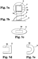
- FIGS. 7(a)-7(e) are illustrations that show package element 1 in accordance with a fifth embodiment of the invention.
- Package element 1 includes package 2 with base 3 and cap 4, getter sheet 5 secured within package 2, device 6 mounted on base 3 within package 2, and electrical connection terminals 7 that are electrically connected to device 6, as described above in reference to FIG. 1 .
- FIG. 7(a) is a top view drawing of package element 1 and FIG. 7(b) is a schematic cross-sectional drawing of the main parts of package element 1.
- package element 1 includes an optical device 9 mounted on the top surface of base 3 within package 2.
- Optical device 9 may comprise an optical sensor, such as an infrared sensor, or any other device that requires incident light to operate properly.
- cap 4 includes an optical transmission window 8 and getter sheet 5 includes an aperture 54.
- package element 1 allows light to pass through optical transmission window 8 in cap 4 and aperture 54 in getter sheet 5 to optical device 9.
- the light may pass through optical transmission window 8 into a light-intake area 44 within package 2 before passing though aperture 54 to optical device 9.
- Optical transmission window 8 may cover a light-intake area 44 located on a top surface of cap 4 outside of package 2.
- Aperture 54 comprises a light penetration area created in getter sheet 5 according to the shape and size of optical device 9.
- getter sheet 5 is secured within package 2 in a condition of elastic deformation by positioning getter sheet 5 between base 3 and cap 4 with at least one end of getter sheet 5 in contact with a portion of package 2.
- Getter sheet 5 may be secured within package 2 using any of the techniques described above. As a result, the condition of elastic deformation may force getter sheet 5 into a vaulted form within package 2.
- Getter sheet 5 is able to absorb the gases effectively by maintaining a minimum amount of contact space between getter sheet 5 and package 2 in order to maximize exposure of getter sheet 5 to the vacuum space within package 2.
- FIG. 7(c) is a plane drawing of an elliptical shaped getter sheet 5 including an aperture 54 substantially centered on getter sheet 5 to form an O-shaped getter sheet 5 that allows light to pass to device 6.
- FIG. 7(d) is a plane drawing of a rectangular shaped getter sheet 5 including an aperture 55 located at an edge of getter sheet 5 to form a U-shaped getter sheet 5 that allows light to pass to device 6.
- FIG. 7(e) is a plane drawing of an elliptical shaped getter sheet 5 including an aperture 56 located at an edge of getter sheet 5 to form a U-shaped getter sheet 5 that allows light to pass to device 6.
- Apertures 54, 55, and 56 comprise light penetration areas created by cutting portions out of getter sheet 5. As illustrated in FIG.
- aperture 54 may be created in getter sheet 5 by cutting a square shape out of getter sheet 5 to block stray light from reaching optical device 9. For example, as illustrated in FIG. 7(b) , when getter sheet 5 is positioned in an oblique shape within package 2, an aperture 54 may be created in getter sheet 5 with dimensions that allow optical device 9, located beneath getter sheet 5, to be seen through aperture 54.
- aperture 54 comprises a light penetration area created by cutting out a substantially centered portion of getter sheet 5.
- apertures 55 and 56 comprise light penetration areas created by cutting out a portion located at an edge of getter sheet 5. The necessary light may then pass through the light penetration area and reach optical device 9.
- the edges surrounding aperture 55 or 56 may be utilized substantially similar to tabs 52 or the tabs formed by folding areas 53 from FIGS. 6(a)-6(d) .
- getter sheet 5 may be effectively secured within package 2 due to the fact that surfaces of the edges surrounding aperture 55 or 56 increase the area of contact with the side surface of cap 4.
- the securing characteristics of getter sheet 5 may be enhanced and any movement of getter sheet 5 within package 2 may be effectively prevented.
- the edges surrounding aperture 55 or 56 may act as legs to hold getter sheet 5 over the top surface of base 3. In this way, height adjustments can be carried out between getter sheet 5 and optical device 9 mounted on the top surface of base 3.
Landscapes
- Light Receiving Elements (AREA)
- Packages (AREA)
- Piezo-Electric Or Mechanical Vibrators, Or Delay Or Filter Circuits (AREA)
Claims (6)
- Packungselement (1), umfassend:ein Gehäuse (2); undeine Getterlage (5), die im Innern des Gehäuses (2) angeordnet ist und eine Lagenlänge und eine Lagenbreite aufweist, wobei die Lagenlänge länger als eine innere lichte Weite des Gehäuses (2) ist, und wobei gegenüberliegende Enden der Getterlage (5) in Richtung der Lagenlänge mit gegenüberliegenden Enden des Gehäuses (2) in Richtung der lichten Weite des Gehäuses (2) derart in Kontakt stehen, dass die Getterlage (5) zumindest entlang der Bogenlänge zum Befestigen der Getterlage (5) im Gehäuse (2) in einem Zustand elastischer Verformung gebogen ist.wobei:- das Gehäuse (2) aus einer Packung mit einer Basis (3) und einem Deckel (4) zusammengesetzt ist, und- wobei zumindest der eine Bereich der Getterlage (5) in Kontakt mit der Basis (3) und/oder dem Deckel (4) steht,- eine elektronische Vorrichtung (6) im Innern des Gehäuses (2) angebracht ist, und- die Getterlage (5) so angeordnet ist, dass diese eine gewölbte Form im Innern des Gehäuses (2) annimmt.
- Packungselement nach Anspruch 1, wobei die Getterlage (5) im Innern des Gehäuses (2) in einer Kuppelform, einer umgekehrten Kuppelform oder einer schrägen Form zwischen der Basis (3) und dem Deckel (4) angeordnet ist.
- Packungselement nach einem der vorhergehenden Ansprüche, das eine optische Vorrichtung (9) aufweist, die an einer Oberseite der Basis (3) im Gehäuse (2) montiert ist, wobei der Deckel (4) ein optisches Übertragungsfenster (8) umfasst und die Getterlage (5) eine Öffnung (54) umfasst, sodass Licht durch das optische Übertragungsfenster (8) und die Öffnung (54) zur optischen Vorrichtung (9) gelangt.
- Packungselement (1) nach Anspruch 3, wobei das optische Übertragungsfenster (8) einen Lichteintrittsbereich (44) im Innern des Gehäuses (2) abdeckt, der auf einer Oberseite des Deckels (4) außerhalb des Gehäuses (2) angeordnet ist.
- Verfahren, das folgende Schritte umfasst:Zusammenbauen eines Gehäuses (2); undBefestigen einer Getterlage (5) mit einer Lagenlänge und einer Lagenbreite im Innern des Gehäuses (2) in einem Zustand elastischer Verformung durch Positionieren der Getterlage (5) mit gegenüberliegenden Enden der Getterlage (5) in Richtung der Lagenlänge in Kontakt mit gegenüberliegenden Enden des Gehäuses (2) in Richtung der lichten Weite des Gehäuses (2) derart, dass die Getterlage (5) zumindest entlang der Bogenlänge gebogen ist,wobei:- die Lagenlänge länger als die lichte Weite des Gehäuses (2) ist,- das Gehäuse (2) aus einem Paket mit einer Basis (3) und einem Deckel (4) zusammengesetzt ist,- das Befestigen der Getterlage (5) das Positionieren der Getterlage (5) mit zumindest einem Bereich davon in Kontakt mit der Basis (3) und/oder dem Deckel (4) umfasst;- eine elektronische Vorrichtung (6) innerhalb des Gehäuses (2) angebracht ist, und- die Getterlage (5) so angeordnet ist, dass diese im Innern des Gehäuses (2) eine gewölbte Form annimmt.
- Verfahren nach Anspruch 5, wobei das Befestigen der Getterlage (5) das Positionieren der Getterlage (5) in einer Kuppelform, einer umgekehrten Kuppelform oder einer schrägen Form zwischen der Basis (3) und der Kappe umfasst (4).
Applications Claiming Priority (1)
| Application Number | Priority Date | Filing Date | Title |
|---|---|---|---|
| JP2004371553A JP4453546B2 (ja) | 2004-12-22 | 2004-12-22 | パッケージ素子 |
Publications (3)
| Publication Number | Publication Date |
|---|---|
| EP1675170A2 EP1675170A2 (de) | 2006-06-28 |
| EP1675170A3 EP1675170A3 (de) | 2009-09-09 |
| EP1675170B1 true EP1675170B1 (de) | 2018-10-03 |
Family
ID=35953969
Family Applications (1)
| Application Number | Title | Priority Date | Filing Date |
|---|---|---|---|
| EP05257838.2A Expired - Lifetime EP1675170B1 (de) | 2004-12-22 | 2005-12-20 | Verpackungselemente und Verfahren zum Befestigen eines Getters |
Country Status (3)
| Country | Link |
|---|---|
| US (1) | US7660495B2 (de) |
| EP (1) | EP1675170B1 (de) |
| JP (1) | JP4453546B2 (de) |
Families Citing this family (7)
| Publication number | Priority date | Publication date | Assignee | Title |
|---|---|---|---|---|
| JP4453546B2 (ja) * | 2004-12-22 | 2010-04-21 | 日産自動車株式会社 | パッケージ素子 |
| JP4517894B2 (ja) * | 2005-03-01 | 2010-08-04 | 日産自動車株式会社 | 真空パッケージ |
| EP2729954B1 (de) * | 2011-07-04 | 2017-12-20 | Tetra Laval Holdings & Finance SA | Elektronenstrahlvorrichtung mit getterfolie und verfahren zur herstellung einer elektronenstrahlvorrichtung mit dieser getterfolie |
| RU2526241C1 (ru) * | 2013-02-12 | 2014-08-20 | Открытое акционерное общество "Специальное конструкторско-технологическое бюро по релейной технике" (ОАО "СКТБ РТ") | Герметичный корпус модуля |
| US9756731B2 (en) * | 2013-02-25 | 2017-09-05 | Kyocera Corporation | Package for housing electronic component and electronic device |
| WO2014160939A2 (en) | 2013-03-28 | 2014-10-02 | Carrier Corporation | Tracking device |
| US20240006267A1 (en) * | 2022-06-29 | 2024-01-04 | Texas Instruments Incorporated | Hermetic Package Cooling Using Silver Tubes with Getter Absorption Material |
Family Cites Families (13)
| Publication number | Priority date | Publication date | Assignee | Title |
|---|---|---|---|---|
| GB935925A (en) | 1961-01-13 | 1963-09-04 | Standard Telephones Cables Ltd | Improvements in or relating to containers including desiccants |
| JPS56137658A (en) * | 1980-03-31 | 1981-10-27 | Chiyou Lsi Gijutsu Kenkyu Kumiai | Semiconductor device |
| CA2162095A1 (en) | 1994-12-27 | 1996-06-28 | Jeffery Alan Demeritt | Getter housing for electronic packages |
| US6203869B1 (en) * | 1996-11-12 | 2001-03-20 | Thomas K. Dougherty | Hydrogen getters and methods for fabricating sealed microelectronic packages employing same |
| US6251344B1 (en) * | 1997-06-27 | 2001-06-26 | Quantum Group, Inc. | Air quality chamber: relative humidity and contamination controlled systems |
| US6291061B1 (en) * | 1999-09-09 | 2001-09-18 | The United States Of America As Represented By The United States Department Of Energy | Hydrogen gettering packing material, and process for making same |
| JP3726717B2 (ja) | 2001-06-22 | 2005-12-14 | 日産自動車株式会社 | ガス吸着素子および赤外線センサ |
| GB2392555A (en) * | 2002-09-02 | 2004-03-03 | Qinetiq Ltd | Hermetic packaging |
| JP2004146599A (ja) | 2002-10-24 | 2004-05-20 | Aisin Seiki Co Ltd | パッケージ素子 |
| US6977391B2 (en) * | 2003-09-25 | 2005-12-20 | Osram Semiconductors Gmbh | Transport balancing diffusion layer for rate limited scavenging systems |
| US20060076634A1 (en) * | 2004-09-27 | 2006-04-13 | Lauren Palmateer | Method and system for packaging MEMS devices with incorporated getter |
| JP4453546B2 (ja) * | 2004-12-22 | 2010-04-21 | 日産自動車株式会社 | パッケージ素子 |
| KR101017608B1 (ko) * | 2005-02-17 | 2011-02-28 | 세스 게터스 에스.피.에이 | 플렉시블 다층 게터 |
-
2004
- 2004-12-22 JP JP2004371553A patent/JP4453546B2/ja not_active Expired - Lifetime
-
2005
- 2005-12-20 EP EP05257838.2A patent/EP1675170B1/de not_active Expired - Lifetime
- 2005-12-20 US US11/312,899 patent/US7660495B2/en active Active
Non-Patent Citations (1)
| Title |
|---|
| None * |
Also Published As
| Publication number | Publication date |
|---|---|
| EP1675170A3 (de) | 2009-09-09 |
| JP4453546B2 (ja) | 2010-04-21 |
| US20060132036A1 (en) | 2006-06-22 |
| JP2006179686A (ja) | 2006-07-06 |
| EP1675170A2 (de) | 2006-06-28 |
| US7660495B2 (en) | 2010-02-09 |
Similar Documents
| Publication | Publication Date | Title |
|---|---|---|
| US7422443B2 (en) | Electric connection box | |
| CA2799044C (en) | Improved vent installation method | |
| EP1675170B1 (de) | Verpackungselemente und Verfahren zum Befestigen eines Getters | |
| US7151236B2 (en) | Push-button electrical switch with deformable actuation and method for making same | |
| EP3391720B1 (de) | Mehrteiliger schutzschild | |
| US5770328A (en) | Battery packaging system and clip for same | |
| US7068514B2 (en) | Protection structure for thermal conducting medium of heat dissipation device | |
| JP6404988B1 (ja) | エンコーダ | |
| CN1032723C (zh) | 表面安装型片状电容器 | |
| US5398169A (en) | Microelectronic package comprising metal housing grounded to board edge | |
| FR2994369A1 (fr) | Boitier de plaque de circuit et appareil electronique ainsi realise | |
| US7638717B1 (en) | Can spring housing contact | |
| EP3351069B1 (de) | Kompaktes elektronisches system und vorrichtung mit solch einem system | |
| JP2021174641A (ja) | バッテリーケース | |
| KR101993763B1 (ko) | 엠오씨 액추에이터 | |
| JP2016164425A (ja) | 取付具およびガラスユニット | |
| JP2000049467A (ja) | シ―ルを備えた金属薄板ケ―シング | |
| JP2008095979A (ja) | 電装品箱 | |
| US11128000B2 (en) | Housing cover and housing having connection point | |
| JPH01171099A (ja) | イオン化式煙感知器の防湿構造 | |
| JP5717693B2 (ja) | 太陽電池モジュール用梱包体 | |
| JP4517894B2 (ja) | 真空パッケージ | |
| US20230361255A1 (en) | Optoelectronic Device | |
| JPH0462478B2 (de) | ||
| JPH0585580A (ja) | 密封容器 |
Legal Events
| Date | Code | Title | Description |
|---|---|---|---|
| PUAI | Public reference made under article 153(3) epc to a published international application that has entered the european phase |
Free format text: ORIGINAL CODE: 0009012 |
|
| AK | Designated contracting states |
Kind code of ref document: A2 Designated state(s): AT BE BG CH CY CZ DE DK EE ES FI FR GB GR HU IE IS IT LI LT LU LV MC NL PL PT RO SE SI SK TR |
|
| AX | Request for extension of the european patent |
Extension state: AL BA HR MK YU |
|
| PUAL | Search report despatched |
Free format text: ORIGINAL CODE: 0009013 |
|
| AK | Designated contracting states |
Kind code of ref document: A3 Designated state(s): AT BE BG CH CY CZ DE DK EE ES FI FR GB GR HU IE IS IT LI LT LU LV MC NL PL PT RO SE SI SK TR |
|
| AX | Request for extension of the european patent |
Extension state: AL BA HR MK YU |
|
| 17P | Request for examination filed |
Effective date: 20100112 |
|
| 17Q | First examination report despatched |
Effective date: 20100312 |
|
| AKX | Designation fees paid |
Designated state(s): DE FR GB |
|
| GRAP | Despatch of communication of intention to grant a patent |
Free format text: ORIGINAL CODE: EPIDOSNIGR1 |
|
| INTG | Intention to grant announced |
Effective date: 20180530 |
|
| GRAS | Grant fee paid |
Free format text: ORIGINAL CODE: EPIDOSNIGR3 |
|
| GRAA | (expected) grant |
Free format text: ORIGINAL CODE: 0009210 |
|
| AK | Designated contracting states |
Kind code of ref document: B1 Designated state(s): DE FR GB |
|
| REG | Reference to a national code |
Ref country code: GB Ref legal event code: FG4D |
|
| REG | Reference to a national code |
Ref country code: DE Ref legal event code: R096 Ref document number: 602005054703 Country of ref document: DE |
|
| REG | Reference to a national code |
Ref country code: DE Ref legal event code: R097 Ref document number: 602005054703 Country of ref document: DE |
|
| PLBE | No opposition filed within time limit |
Free format text: ORIGINAL CODE: 0009261 |
|
| STAA | Information on the status of an ep patent application or granted ep patent |
Free format text: STATUS: NO OPPOSITION FILED WITHIN TIME LIMIT |
|
| 26N | No opposition filed |
Effective date: 20190704 |
|
| REG | Reference to a national code |
Ref country code: DE Ref legal event code: R084 Ref document number: 602005054703 Country of ref document: DE |
|
| REG | Reference to a national code |
Ref country code: GB Ref legal event code: 746 Effective date: 20230922 |
|
| PGFP | Annual fee paid to national office [announced via postgrant information from national office to epo] |
Ref country code: DE Payment date: 20241121 Year of fee payment: 20 |
|
| PGFP | Annual fee paid to national office [announced via postgrant information from national office to epo] |
Ref country code: GB Payment date: 20241122 Year of fee payment: 20 |
|
| PGFP | Annual fee paid to national office [announced via postgrant information from national office to epo] |
Ref country code: FR Payment date: 20241121 Year of fee payment: 20 |
|
| REG | Reference to a national code |
Ref country code: DE Ref legal event code: R079 Ref document number: 602005054703 Country of ref document: DE Free format text: PREVIOUS MAIN CLASS: H01L0023260000 Ipc: H10W0076480000 |
|
| REG | Reference to a national code |
Ref country code: DE Ref legal event code: R071 Ref document number: 602005054703 Country of ref document: DE |
|
| REG | Reference to a national code |
Ref country code: GB Ref legal event code: PE20 Expiry date: 20251219 |