EP1675001A1 - Duplicate synchronization system and method of operating duplicate synchronization system - Google Patents
Duplicate synchronization system and method of operating duplicate synchronization system Download PDFInfo
- Publication number
- EP1675001A1 EP1675001A1 EP05027612A EP05027612A EP1675001A1 EP 1675001 A1 EP1675001 A1 EP 1675001A1 EP 05027612 A EP05027612 A EP 05027612A EP 05027612 A EP05027612 A EP 05027612A EP 1675001 A1 EP1675001 A1 EP 1675001A1
- Authority
- EP
- European Patent Office
- Prior art keywords
- dma engine
- memory
- controller
- data
- read
- Prior art date
- Legal status (The legal status is an assumption and is not a legal conclusion. Google has not performed a legal analysis and makes no representation as to the accuracy of the status listed.)
- Withdrawn
Links
Images






Classifications
-
- G—PHYSICS
- G06—COMPUTING OR CALCULATING; COUNTING
- G06F—ELECTRIC DIGITAL DATA PROCESSING
- G06F11/00—Error detection; Error correction; Monitoring
- G06F11/07—Responding to the occurrence of a fault, e.g. fault tolerance
- G06F11/16—Error detection or correction of the data by redundancy in hardware
- G06F11/1658—Data re-synchronization of a redundant component, or initial sync of replacement, additional or spare unit
-
- G—PHYSICS
- G06—COMPUTING OR CALCULATING; COUNTING
- G06F—ELECTRIC DIGITAL DATA PROCESSING
- G06F13/00—Interconnection of, or transfer of information or other signals between, memories, input/output devices or central processing units
- G06F13/14—Handling requests for interconnection or transfer
- G06F13/16—Handling requests for interconnection or transfer for access to memory bus
- G06F13/1605—Handling requests for interconnection or transfer for access to memory bus based on arbitration
- G06F13/1652—Handling requests for interconnection or transfer for access to memory bus based on arbitration in a multiprocessor architecture
- G06F13/1657—Access to multiple memories
-
- G—PHYSICS
- G06—COMPUTING OR CALCULATING; COUNTING
- G06F—ELECTRIC DIGITAL DATA PROCESSING
- G06F13/00—Interconnection of, or transfer of information or other signals between, memories, input/output devices or central processing units
- G06F13/14—Handling requests for interconnection or transfer
- G06F13/20—Handling requests for interconnection or transfer for access to input/output bus
- G06F13/28—Handling requests for interconnection or transfer for access to input/output bus using burst mode transfer, e.g. direct memory access DMA, cycle steal
Definitions
- the present invention relates to a duplicate synchronization system.
- the present invention relates to a duplicate synchronization system and a method of copying the contents of a memory in the duplicate synchronization system.
- a fault tolerant (FT) computer is known as a computer providing high reliability.
- FT computer hardware modules constituting a system are duplicated or multiplexed, and these hardware modules are controlled so as to operate in synchronization with each other.
- a system such as the FT computer system is referred to as a "duplicate synchronization system" hereinafter.
- the duplicate synchronization system even when a fault occurs in a certain section (module), it is possible to continue processing in a normal module by separating the fault module. That is to say, the duplicate synchronization system has excellent fault tolerance and availability (for example, refer to Japanese Laid Open Patent Application JP-P-Heisei 10-293697).
- the duplicate synchronization system consists of a first system and a second system.
- data stored in main memories of both systems are controlled to be always consistent with each other.
- data stored in the main memories of both systems are not consistent. It is therefore necessary to copy data stored in the main memory of one system to the main memory of the other system as soon as possible and thereby make the both system consistent with each other.
- the one system as a copy source When the one system as a copy source is normally operated during a data restoration process, the data stored in the main memory of the one system is updated. It is therefore necessary to suspend the operation of the whole duplicate synchronization system during the data restoration process. Since the increase in the time for the data restoration disturbs the services, it is preferable that the suspended period is as short as possible. In particular, capacity of the main memory goes on increasing in recent years, and thus a time required for the data copy between the both systems becomes longer and longer. The time required for the data copy is referred to as a "memory copy time" hereinafter. In addition, transfer performance of a data link path connecting between the systems is lower as compared with data transfer performance in an LSI. This is also one of factors which cause the increase in the memory copy time. It is desired to reduce the memory copy time and to shorten the suspended period of the duplicate synchronization system.
- a duplicate synchronization system has a first system, and a second system which operates in synchronization with the first system.
- the first system and the second system are connected to each other through a plurality of data link paths.
- the first system includes: a first memory; a first controller controlling a read/write for the first memory; and a first DMA engine accessing the first controller.
- the second system includes: a second memory; a second controller controlling a read/write for the second memory; and a second DMA engine accessing the second controller.
- each of the first DMA engine and the second DMA engine sets the source to any of the first DMA engine and the second DMA engine.
- the first controller is configured to read out a data from the first memory in response to the read command, and send the read data back to the source.
- the second controller is configured to read out a data from the second memory in response to the read command, and send the read data back to the source.
- the first DMA engine sends to the first controller not only a first read command in which the source is set to the first DMA engine but also a second read command in which the source is set to the second DMA engine.
- the first controller reads out data from the first memory in response to respective of the first read command and the second read command, and sends the read data to respective of the first DMA engine and the second DMA engine.
- the first DMA engine and the second DMA engine write the read data to the second memory through the second controller.
- the first controller reads out data stored in a first address group in the first memory in response to the first read command, and reads out data stored in a second address group different from the first address group in the first memory in response to the second read command.
- the first address group may be one of an odd address group and an even address group
- the second address group may be the other of the odd address group and the even address group.
- the second DMA engine sends to the first controller the read command in which the source is set to the second DMA engine.
- the first controller reads out data from the first memory in response to the read command, and sends the read data back to the second DMA engine.
- the second DMA engine writes the read data to the second memory through the second controller.
- the first DMA engine sends to the first controller the read command in which the source is set to the first DMA engine.
- the first controller reads out data from the first memory in response to the read command, and sends the read data back to the first DMA engine.
- the first DMA engine writes the read data to the second memory through the second controller.
- the first DMA engine can send to the first controller the read command in which the source is set to the second DMA engine.
- the first controller reads out data from the first memory in response to the read command, and sends the read data to the second DMA engine.
- the second DMA engine writes the read data to the second memory through the second controller.
- a DMA engine is provided.
- the DMA engine is in a duplicate synchronization system which has a first system and a second system operating in synchronization with the first system.
- the DMA engine can issues a command by designating any of a first ID indicative of a DMA engine in the first system and a second ID indicative of a DMA engine in the second system as an ID of a source of the command.
- a method of operating the duplicate synchronization system is provided.
- at least one of the first DMA engine and the second DMA engine is used in a data copy from the first memory and the second memory. Both of the first DMA engine and the second DMA engine may be used.
- one of the first DMA engine and the second DMA engine is used for reading out data stored in an odd address group in the first memory
- the other of the first DMA engine and the second DMA engine is used for reading out data stored in an even address group in the first memory.
- one of the first DMA engine and the second DMA engine which does not fail is used as the at least one DMA engine.
- the memory copy time is reduced.
- the suspended period of the system operation is shortened.
- Fig. 1 is a block diagram showing a configuration of a duplicate synchronization system 1 according to the present invention.
- the duplicate synchronization system 1 includes a first system 1a and a second system 1b.
- the first system 1a and the second system 1b operate in synchronization with each other.
- the first system 1a is provided with a control LSI 2a, a CPU 3a and a main memory 4a.
- the control LSI 2a is connected to the CPU 3a and the main memory 4a.
- the control LSI 2a includes a CPU controller 5a, a memory controller 6a, a router 7a, an IO comparator 8a, an IO controller 9a, a DMA engine 10a, an IB (In-Bound) link controller 11a and an OB (Out-Bound) link controller 12a.
- the second system 1b has the same configuration as that of the first system 1a. That is, the second system 1b is provided with a control LSI 2b, a CPU 3b and a main memory 4b.
- the control LSI 2b is connected to the CPU 3b and the main memory 4b.
- the control LSI 2b includes a CPU controller 5b, a memory controller 6b, a router 7b, an IO comparator 8b, an IO controller 9b, a DMA engine 10b, an IB link controller 11b and an OB link controller 12b.
- the CPU controller 5 controls a connecting bus to the CPU 3.
- the memory controller 6 controls an access (read/write) to the memory 4.
- the router 7 has a function of controlling routing, and routes each request to any of a CPU system, a memory system and an IO system.
- the IO controller 9 controls a connecting bus to IO devices.
- the first system 1a and the second system 1b are connected with each other via a plurality of data link paths 13a, 13b, 14a and 14b.
- Each data link path 13 is used for In-Bound data transfer from the IO side to the CPU/memory side, while each data link path 14 is used for Out-Bound data transfer from the CPU/memory side to the IO side.
- the IB link controller 11 controls the In-Bound data transfer (hereinafter, referred to as an IB data transfer).
- the OB link controller 12 controls the Out-Bound data transfer (hereinafter, referred to as an OB data transfer).
- An IB data transfer from the first system 1a to the second system 1b is executed through the IB link controller 11a, the data link path 13a and the OB link controller 12b.
- An OB data transfer from the first system 1a to the second system 1b is executed through the OB link controller 12a, the data link path 14a and the IB link controller 11b.
- An IB data transfer from the second system 1b to the first system 1a is executed through the IB link controller 11b, the data link path 13b and the OB link controller 12a.
- An OB data transfer from the second system 1b to the first system 1a is executed through the OB link controller 12b, the data link path 14b and the IB link controller 11a.
- the IO comparator 8 compares the Out-Bound access of own system with the Out-Bound access from the other system in an operation.
- the DMA engine (DMA controller) 10 controls a DMA transfer.
- DMA Direct Memory Access
- data are directly transferred between an I/O device and the memory 4 without involving the CPU 3.
- the DMA engine 10a of the first system 1a is capable of accessing the memory controller 6a via the router 7a.
- the DMA engine 10a is also capable of accessing the memory controller 6b of the second system 1b via the IB link controller 11a.
- the DMA engine 10b of the second system 1b is capable of accessing the memory controller 6b via the router 7b.
- the DMA engine 10b is also capable of accessing the memory controller 6a of the first system 1a via the IB link controller 11b.
- Fig. 2 shows a configuration of the DMA engine 10 according to the present invention in more, detail.
- the DMA engine 10 according to the present invention has a config-register 20.
- Set (registered) in the config-register 20 are a "DMA operation mode", a "copy source ID”, a “copy destination ID”, a "memory copy start address”, a "size” and a "control data (information)".
- the "DMA operation mode” the following three kinds can be set: 1. both system master mode; 2. both system slave mode; and 3. single system master mode. An operation in each mode will be described later in detail.
- Set in the "copy source ID” is an ID of a main memory 4 as a copy source
- set in the "copy destination ID” is an ID of a main memory 4 as a copy destination.
- a head address at which a copy is started is set in the "memory copy start address”.
- a size of a memory region to be copied is set in the "size”.
- the DMA engine 10 issues as many read commands as the size while updating a target address.
- Set in the "control data” are a "camouflage setting", a DMA start bit and the like. The camouflage setting will be described later in detail.
- the above-mentioned settings for the config-register 20 are performed by the CPU 3. That is, the DMA engine 10a of the first system 1a has a config-register 20a, and the settings for the config-register 20a are performed by the CPU 3a or the CPU 3b. Also, the DMA engine 10b of the second system 1b has a config-register 20b, and the settings for config-register 20b are performed by the CPU 3b or the CPU 3a.
- a request (command) from a component to another component is executed through transferring packets.
- a command issuing side namely, a packet transmitting side is referred to as a "Source”.
- a packet receiving side is referred to as a "Target”.
- Fig. 3 shows contents of the packets used in the duplicate synchronization system 1 according to the present invention.
- a config-packet is generated by the CPU 3 in order to make settings in the config-register 20.
- the config-packet includes a "target ID” as an ID indicating a target, a "source ID” as an ID indicating a source, a "Config-Write command” issued by the CPU 3, a "register address” and "register data” set in the config-register 20.
- a read-packet is generated by the DMA engine 10 in order to read out data from the main memory 4.
- the read-packet includes a "target ID”, a "source ID”, a "DMA-Memory-Copy-Read command” issued by the DMA engine 10 and a "memory address”.
- a completion-packet is issued by the memory controller 6.
- the completion-packet includes a "target ID”, a “source ID”, a “Completion command” issued by the memory controller 6, a "memory address” and “memory data” read out from the main memory 4.
- a write-packet is generated by the DMA engine 10 in order to write the data in the main memory 4.
- the write-packet includes a "target ID”, a "source ID”, a "DMA-Memory-Copy-Write command” issued by the DMA engine 10, a "memory address” and the "memory data”.
- the CPU 3 can transmit config-packets to respective of the DMA engine 10a (first DMA engine) of the first system 1a and the DMA engine 10b (second DMA engine) of the second system 1b.
- the settings of the corresponding config-register 20 are executed by the Config-Write command.
- the DMA engine 10 can send a read-packet (read command) to the memory controller 6a of the first system 1a and the memory controller 6b of the second system 1b.
- the target ID is set to a memory controller 6 corresponding to the copy source ID indicated in the config-register 20.
- the memory controller 6 receives the read-packet from the DMA engine 10. In response to the DMA-Memory-Copy-Read command (read command), the memory controller 6 reads out data from the corresponding main memory 4. After reading out the data, the memory controller 6 sends a completion-packet back to the router 7.
- the memory controller 6 interchanges the target ID and the source ID indicated in the read-packet, and sets them as the target ID and the source ID of the completion-packet.
- the source ID of the completion-packe t is set to the target ID of the read-packet
- the target ID of the completion-packet is set to the source ID of the read-packet.
- the router 7 When receiving the completion-packet, the router 7 checks the target ID. Then, in accordance with the target ID, the router 7 forwards the completion-packet to the DMA engine 10 of own system or to the DMA engine 10 of another system via the OB link controller 12.
- the DMA engine 10 When receiving the completion-packet, the DMA engine 10 outputs a write-packet (write command).
- the target ID is set to a memory controller 6 corresponding to the copy destination ID indicated in the config-register 20.
- the memory controller 6 receives the write-packet.
- the memory controller 6 In response to the DMA-Memory-Copy-Write command (write command), the memory controller 6 writes the memory data to the corresponding main memory 4.
- the DMA engine 10 is capable of setting the source of the read-packet to either the first DMA engine 10a or the second DMA engine 10b.
- the first DMA engine 10a of the first system 1a can send not only a read-packet in which the source is set to the first DMA engine 10a but also a read-packet in which the source is set to the second DMA engine 10b.
- the read-packet in which the source is set to the second DMA engine 10b is a "camouflage-packet".
- the memory controller 6 receiving the camouflage-packet interprets that the camouflage-packet as the read-packet is transmitted from the second DMA engine 10b. Therefore, a completion-packet responding to the camouflage-packet is transmitted not to the first DMA engine 10a but to the second DMA engine 10b. What camouflages are performed is set as the "camouflage setting" in the config-register 20 (see Fig. 2).
- both the first DMA engine 10a and the second DMA engine 10b are used (both system mode).
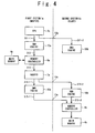
- Fig. 4 shows a flow of a processing according to the present embodiment.
- the CPU 3a of the first system 1a confirms that the first DMA engine 10a and the second DMA engine 10b are available and no errors occur on the data link paths 13 and 14. Then, the CPU 3a transmits a config-packet to the first DMA engine 10a (Step S11-1). Also, the CPU 3a transmits a config-packet to the second DMA engine 10b via the data link path 14a (Out-Bound) (Step S11-2). Thereby, the settings of the config-register 20a and the config-register 20b are carried out.
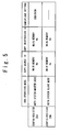
- Fig. 5 shows contents of the config-registers 20a and 20b which are set.
- the DMA operation mode is set to the "both system master mode".
- the config-register 20b the DMA operation mode is set to the "both system slave mode". That is to say, in the present embodiment, the first system 1a functions as a master, while the second system 1b functions as a slave.
- the camouflage setting is set to "odd/even". According to the setting, as described later, the camouflage is enabled in accordance with whether a read address corresponds to an odd number or an even number.
- the copy source is set to the main memory 4a and the copy destination is set to the main memory 4b.
- the second DMA engine 10b Since the DMA operation mode is set to the "both system slave mode", the second DMA engine 10b does not generate a read-packet. On the other hand, since the DMA operation mode is set to the "both system master mode", the first DMA engine 10a generates a read-packet based on the camouflage setting and outputs the generated read-packet.
- Fig. 6 shows contents of the read-packets generated by the first DMA engine 10a.
- the first DMA engine 10a generates two kinds of read-packets.
- the source of a first read-packet is set to the first DMA engine 10a
- the source of a second read-packet is set to the second DMA engine 10b.
- the second read-packet is a "camouflage-packet".
- the target is set to the memory controller 6a in accordance with the copy source ID (main memory 4a) indicated in the config-register 20a.
- the first read-packet is related to an odd address group in the main memory 4a
- the second read-packet is related to an even address group in the main memory 4a.
- the first read-packet is used for reading out data stored in the odd address group.
- the second read-packet is used for reading out data stored in the even address group. It should be noted that the first read-packet can be related to the even address group, and the second read-packet can be related to the odd address group.
- the first DMA engine 10a sends the generated first read-packet and second read-packet to the memory controller 6a through the router 7a (Step S12).
- the memory controller 6a receives the first read-packet, the memory controller 6a reads out a read data from an odd address of the main memory 4a in response to the DMA-Memory-Copy-Read command. Then, the memory controller 6a sends a first completion-packet including the read data to the router 7a (Step S13).
- the memory controller 6a when the memory controller 6a receives the second read-packet, the memory controller 6a reads out a read data from an even address of the main memory 4a in response to the DMA-Memory-Copy-Read command. Then, the memory controller 6a sends a second completion-packet including the read data back to the router 7a (Step S13).
- Fig. 7 shows contents of the first completion-packet and the second completion-packet output from the memory controller 6a.
- the memory controller 6a interchanges the target ID and the source ID indicated in the read-packet, and sets them as the target ID and the source ID of the completion-packet. That is, in the first completion-packet, the target is set to the first DMA engine 10a and the source is set to the memory controller 6a. In the second completion-packet, the target is set to the second DMA engine 10b and the source is set to the memory controller 6a.
- the router 7a when receiving the completion-packet, the router 7a checks its target ID. When the router 7a receives the first completion-packet, namely, when the target is the first DMA engine 10a, the router 7a forwards the first completion-packet back to the first DMA engine 10a via the IO comparator 8a (Step S14-1). On the other hand, when the router 7b receives the second completion-packet, namely, when the target is the second DMA engine 10b, the router 7a forwards the second completion-packet to the OB link controller 12a. As a result, the second completion-packet is transmitted to the second DMA engine 10b through the data link path 14a, the IB link controller 11b and the IO comparator 8b (Step S14-2).
- the first DMA engine 10a When receiving the first completion-packet, the first DMA engine 10a generates a write-packet.
- the target is set to the memory controller 6b in accordance with the copy destination ID (main memory 4b) indicated in the config-register 20a. Therefore, the write-packet output from the first DMA engine 10a is transmitted to the memory controller 6b through the IB link controller 11a, the data link path 13a, the OB link controller 12b and the router 7b (Step S15-1).
- the memory controller 6b When receiving the write-packet, the memory controller 6b writes the read data to the odd address of the main memory 4b in response to the DMA-Memory-Copy-Write command.
- the DMA engine 10 whose operation mode is set to the "both system slave mode" generates only the write-packet. That is, when receiving the second completion-packet, the second DMA engine 10b generates a write-packet.
- the target is set to the memory controller 6b in accordance with the copy destination ID (main memory 4b) indicated in the config-register 20b. Therefore, the write-packet output from the second DMA engine 10b is transmitted to the memory controller 6b through the router 7b (Step S15-2).
- the memory controller 6b writes the read data to the even address of the main memory 4b in response to the DMA-Memory-Copy-Write command.
- the memory data are copied from the main memory 4a to the main memory 4b.
- the camouflage packet is generated in accordance with whether the target address indicates odd number or the even number.
- the camouflage setting is not limited thereto.
- the memory space of the main memory 4 is divided into two sections, and two start addresses are provided.
- the first read-packet is related to a first address group
- the second read-packet is related to a second address group different from the first address group.
- the first DMA engine 10a since the first DMA engine 10a generates the camouflage-packet, it is possible to carry out the data copy by simultaneously using both the first DMA engine 10a and the second DMA engine 10b.
- the second DMA engine 10b plays a role of generating the write-packet corresponding to the second completion-packet.
- load on the first DMA engine 10a is reduced. Therefore, the copy speed of the memory data is improved as a whole, and thus a total time required for the memory copy is reduced. That is, the suspended period of the system operation can be shortened.
- the write-packet generated by the first DMA engine 10a is transmitted to the memory controller 6b via the data link path 13a, and the second completion-packet is transmitted to the second DMA engine 10b via the data link path 14a.
- the transmission between the systems, namely, the data copy by simultaneously using both the data link paths 13a and 14a.
- the copy speed of the memory data is improved as a whole, and thus a total time required for the memory copy is reduced. Therefore, the suspended period of the system operation can be shortened.
- the second DMA engine 10b needs not to issue any read-packet (read command). In other words, it is not necessary to transmit a read command from the second DMA engine 10b to the memory controller 6a via the IB link controller 11b, the data link path 13b, the OB link controller 12a and the router 7a. A transmission of a read command between the systems is omitted. As a result, the copy speed of the memory data is improved as a whole, and thus a total time required for the memory copy is reduced. Therefore, the suspended period of the system operation can be shortened.
- Described in a second embodiment is a case when the first DMA engine 10a of the first system 1a fails. In this case, only the second DMA engine 10b which does not fail is used (single system mode).
- Fig. 8 shows a flow of a processing according to the present embodiment.
- the CPU 3a of the first system 1a detects the failure of the first DMA engine 10a, and confirms that the second DMA engine 10b is available and no errors occur on the data link paths 13 and 14. After that, the CPU 3a sends a config-packet to the second DMA engine 10b via the data link path 14a (Out-Bound) (Step S21). Thereby, the settings of the config-register 20b are executed.
- Fig. 9 shows contents of the config-register 20b which is set.
- the DMA operation mode is set to the "single system master mode".
- the copy source is set to the main memory 4a, while the copy destination is set to the main memory 4b.
- the DMA operation mode is set to the "single system master mode"
- the camouflage setting is not available.
- the DMA start bit is turned ON, the DMA operation is started.
- the second DMA engine 10b generates a read-packet.
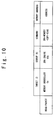
- Fig. 10 shows contents of the read-packet generated by the second DMA engine 10b.
- the source of the read-packet is set to the second DMA engine 10b.
- the target of the read-packet is set to the memory controller 6a in accordance with the copy source ID (main memory 4a) indicated in the config-register 20b. Therefore, the read-packet output from the second DMA engine 10b is transmitted to the memory controller 6a via the IB link controller 11b, the data link path 13b, the OB link controller 12a and the router 7a (Step S22 in Fig. 8).
- the memory controller 6a receives the read-packet.
- the memory controller 6a reads out read data from the main memory 4a in response to the DMA-Memory-Copy-Read command.
- the memory controller 6a sends a completion-packet including the read data to the router 7a (Step S23).
- the memory controller 6a interchanges the target ID and the source ID indicated in the read-packet, and sets them as the target ID and the source ID of the completion-packet. That is to say, in the completion-packet, the target is set to the second DMA engine 10b, and the source is set to the memory controller 6a.
- the router 7a When receiving the completion-packet, the router 7a checks the target ID. Since the target here is the second DMA engine 10b, the router 7a forwards the completion-packet to the OB link controller 12a. Thereby, the completion-packet is transmitted to the second DMA engine 10b through the data link path 14a, the IB link controller 11b and the IO comparator 8b (Step S24).
- the second DMA engine 10b When receiving the completion-packet, the second DMA engine 10b generates a write-packet.
- the target is set to the memory controller 6b in accordance with the copy destination ID (main memory 4b) indicated in the config-register 20b. Therefore, the write-packet output from the second DMA engine 10b is transmitted to the memory controller 6b through the router 7b (Step S25).
- the memory controller 6b writes the read data to the main memory 4b in response to the DMA-Memory-Copy-Write command.
- Described in a third embodiment is a case when the second DMA engine 10b of the second system 1b fails. In this case, only the first DMA engine 10a which does not fail is used (single system mode).
- Fig. 11 shows a flow of a processing according to the present embodiment.
- the CPU 3a of the first system 1a detects the failure of the second DMA engine 10b, and confirms that the first DMA engine 10a is available and no errors occur on the data link paths 13 and 14. After that, the CPU 3a sends a config-packet to the first DMA engine 10a (Step S31). Thereby, the settings of the config-register 20a are executed.
- Fig. 12 shows contents of the config-register 20a which is set.
- the DMA operation mode is set to the "single system master mode”.
- the copy source is set to the main memory 4a, and the copy destination is set to the main memory 4b.
- the DMA operation mode is set to the "single system master mode"
- the camouflage setting is not available.
- the DMA start bit is turned ON, the DMA operation is started.
- the first DMA engine 10a generates a read-packet.
- Fig. 13 shows contents of the read-packet generated by the first DMA engine 10a.
- the source of the read-packet is set to the first DMA engine 10a.
- the target of the read-packet is set to the memory controller 6a in accordance with the copy source ID (main memory 4a) indicated in the config-register 20a. Therefore, the read-packet output from the first DMA engine 10a is transmitted to the memory controller 6a through the router 7a (Step S32 in Fig. 11).
- the memory controller 6a receives the read-packet.
- the memory controller 6a reads out read data from the main memory 4a in response to the DMA-Memory-Copy-Read command.
- the memory controller 6a transmits a completion-packet including the read data to the router 7a (Step S33).
- the memory controller 6a interchanges the target ID and the source ID indicated in the read-packet, and sets them as the target ID and the source ID of the completion-packet. That is to say, in the completion-packet, the target is set to the first DMA engine 10a, and the source is set to the memory controller 6a.
- the router 7a When receiving the completion-packet, the router 7a checks its target ID. Since the target here is the first DMA engine 10a, the router 7a forwards the completion-packet to the first DMA engine 10a via the IO comparator 8a (Step S34).
- the first DMA engine 10a When receiving the completion-packet, the first DMA engine 10a generates a write-packet.
- the target is set to the memory controller 6b in accordance with the copy destination ID (main memory 4b) indicated in the config-register 20a. Therefore, the write-packet output from the first DMA engine 10a is transmitted to the memory controller 6b through the IB link controller 11a, the data link path 13a, the OB link controller 12b and the router 7b (Step S35).
- the memory controller 6b When receiving the write-packet, the memory controller 6b writes the read data to the main memory 4b in response to the DMA-Memory-Copy-Write command.
- the present embodiment as described above, it is possible to copy the memory data from the first main memory 4a to the second main memory 4b even when the second DMA engine 10b fails. Furthermore, the data link path which is used in the present embodiment is only the data link path 13a as shown in Fig. 11. Therefore, the present embodiment has an excellent tolerance to failures of the data link paths.
- a fourth embodiment is a kind of the both system mode different from the first embodiment. That is, both the first DMA engine 10a and the second DMA engine 10b are used.
- Fig. 14 shows a flow of a processing according to the present embodiment.
- the CPU 3a of the first system 1a confirms that the first DMA engine 10a and the second DMA engine 10b are available. After that, the CPU 3a transmits a config-packet to the first DMA engine 10a (Step S41-1). Also, the CPU 3a transmits a config-packet to the second DMA engine 10b via the data link path 14a (Out-Bound) (Step S41-2). Thereby, the settings of the config-register 20a and the config-register 20b are executed.
- Fig. 15 shows contents of the config-registers 20a and 20b which are set.
- the DMA operation mode is set to the "both system master mode" in the config-register 20a.
- the DMA operation mode is set to the "both system slave mode" in the config-register 20b. That is to say, in the present embodiment, the first system 1a functions as a master, and the second system 1b functions as a slave.
- the camouflage setting is set to "change all”. According to the setting, as described later, all read-packets are camouflaged.
- the copy source is set to the main memory 4a, and the copy destination is set to the main memory 4b.
- the second DMA engine 10b Since the DMA operation mode is set to the "both system slave mode", the second DMA engine 10b does not output any read-packet. On the other hand, since the DMA operation mode is set to the "both system master mode", the first DMA engine 10a generates a read-packet based on the above-mentioned camouflage setting, and outputs the generated read-packet.
- Fig. 16 shows contents of the read-packet generated by the first DMA engine 10a.
- all read-packets are "camouflage-packets".
- the sources of the all read-packets are set to the second DMA engine 10b.
- the targets of the all read-packets are set to the memory controller 6a in accordance with the copy source ID (main memory 4a) indicated in the config-register 20a. Therefore, the read-packet output from the first DMA engine 10a is transmitted to the memory controller 6a through the router 7a (Step S42 in Fig. 14).
- the memory controller 6a receives the read-packet.
- the memory controller 6a reads out read data from the main memory 4a in response to the DMA-Memory-Copy-Read command.
- the memory controller 6a sends a completion-packet including the read data to the router 7a (Step S43).
- the memory controller 6a interchanges the target ID and the source ID indicated in the read-packet, and sets them as the target ID and the source ID of the completion-packet. That is to say, in the completion-packet, the target is set to the second DMA engine 10b, and the source is set to the memory controller 6a.
- the router 7a When receiving the completion-packet, the router 7a checks its target ID. Since the target here is the second DMA engine 10b, the router 7a forwards the completion-packet to the OB link controller 12a. Thereby, the completion-packet is transmitted to the second DMA engine 10b via the data link path 14a, the IB link controller 11b and the IO comparator 8b (Step S44).
- the second DMA engine 10b When receiving the completion-packet, the second DMA engine 10b generates a write-packet.
- the target is set to the memory controller 6b in accordance with the copy destination ID (main memory 4b) indicated in the config-register 20b. Therefore, the write-packet output from the second DMA engine 10b is transmitted to the memory controller 6b through the router 7b (Step S45).
- the memory controller 6b writes the read data to the main memory 4b in response to the DMA-Memory-Copy-Write command.
- the data link path which is used is only the data link path 14a as shown in Fig. 14. Therefore, the present embodiment has an excellent tolerance to failures of the data link paths.
- the first DMA engine 10a since the first DMA engine 10a generates the camouflage-packet, it is possible to carry out the data copy by simultaneously using both the first DMA engine 10a and the second DMA engine 10b.
- the second DMA engine 10b plays a role of generating the write-packet corresponding to the completion-packet. As a result, load on the first DMA engine 10a is reduced. Therefore, the copy speed of the memory data is improved as a whole, and thus a total time required for the memory copy is reduced. That is, the suspended period of the system operation can be shortened.
- the second DMA engine 10b needs not to issue any read-packet (read command). In other words, it is not necessary to transmit a read command from the second DMA engine 10b to the memory controller 6a via the IB link controller 11b, the data link path 13b, the OB link controller 12a and the router 7a. A transmission of a read command between the systems is omitted. As a result, the copy speed of the memory data is improved as a whole, and thus a total time required for the memory copy is reduced. Therefore, the suspended period of the system operation can be shortened.
- the present invention is also useful when an error occurs on the data link paths 13, 14.
- the second embodiment or the fourth embodiment can be applied. That is, when the CPU 3a detects an error of the data link path 13a, the CPU 3a makes the settings of the config-register 20 as in the second embodiment or the fourth embodiment. As shown in Fig. 8 or Fig. 14, the data link path 13a is not used in those embodiments. It is therefore possible to copy the memory data from the first main memory 4a to the second main memory 4b.
- the third embodiment can be applied. That is, when the CPU 3a detects an error of the data link path 14a, the CPU 3a makes the settings of the config-register 20 as in the third embodiment. As shown in Fig. 11, the data link path 14a is not used in the third embodiment. It is therefore possible to copy the memory data from the first main memory 4a to the second main memory 4b.
- the first, third and fourth embodiments can be applied. That is, when the CPU 3a detects an error of the data link path 13b, the CPU 3a makes the settings of the config-register 20 as in the first, third, or fourth embodiments. As shown in Figs. 4, 11 and 14, the data link path 13b is not used in those embodiments. It is therefore possible to copy the memory data from the first main memory 4a to the second main memory 4b.
- the fourth embodiment can be applied. That is, when the CPU 3a detects errors of the data link paths 13a and 13b, the CPU 3a makes the settings of the config-register 20 as in the fourth embodiment. As shown in Fig. 14, the data link paths 13a and 13b are not used in the fourth embodiment. It is therefore possible to copy the memory data from the first main memory 4a to the second main memory 4b.
- the third embodiment can be applied. That is, when the CPU 3a detects errors of the data link paths 14a and 14b, the CPU 3a makes the settings of the config-register 20 as in the third embodiment. As shown in Fig. 11, the data link paths 14a and 14b are not used in the third embodiment. It is therefore possible to copy the memory data from the first main memory 4a to the second main memory 4b.
- the second embodiment or the fourth embodiment can be applied. That is, when the CPU 3a detects errors of the data link paths 13a and 14b, the CPU 3a makes the settings of the config-register 20 as in the second embodiment or the fourth embodiment. As shown in Fig. 8 or Fig. 14, the data link paths 13a and 14b are not used in those embodiments. It is therefore possible to copy the memory data from the first main memory 4a to the second main memory 4b.
- the third embodiment can be applied. That is, when the CPU 3a detects errors of the data link paths 14a and 13b, the CPU 3a makes the settings of the config-register 20 as in the third embodiment. As shown in Fig. 11, the data link paths 14a and 13b are not used in the third embodiment. It is therefore possible to copy the memory data from the first main memory 4a to the second main memory 4b.
- the DMA engine 10 and the method of operating the same of the present invention the memory copy time is reduced. Therefore, the suspended period of the system operation is shortened. Moreover, it is possible to carry out the memory copy even when the DMA engine of one system fails. Furthermore, it is also possible to carry out the memory copy even when a part of the data link paths connecting between the both systems fails. It should be noted that the present invention can be also applied to a multiplex synchronization system constituted by three or more systems. Even in that case, the same effect can be obtained. Also, the router 7 may appropriately designate the target ID, instead of the DMA engine 10 generating the camouflage-packet.
Landscapes
- Engineering & Computer Science (AREA)
- Theoretical Computer Science (AREA)
- Physics & Mathematics (AREA)
- General Engineering & Computer Science (AREA)
- General Physics & Mathematics (AREA)
- Quality & Reliability (AREA)
- Hardware Redundancy (AREA)
- Techniques For Improving Reliability Of Storages (AREA)
Abstract
The duplicate synchronization system (1) has: a first system (1a); and a second system (1b) operating in synchronization with the first system (1a). The first and the second systems (1a, 1b) are connected to each other. The first system (1a) includes: a first memory (4a); a first memory controller (6a); and a first DMA engine (10a). The second system (1b) includes: a second memory (4b); a second memory controller (6b); and a second DMA engine (10b). When sending a read command to the memory controller (6), each DMA engine (10) can set a source of the read command to either the first DMA engine (10a) or the second DMA engine (10b). The memory controller (6) reads out data from the memory (4) in response to the read command, and sends the read data back to the source indicated in the read command.
Description
- The present invention relates to a duplicate synchronization system. In particular, the present invention relates to a duplicate synchronization system and a method of copying the contents of a memory in the duplicate synchronization system.
- A fault tolerant (FT) computer is known as a computer providing high reliability. In the FT computer, hardware modules constituting a system are duplicated or multiplexed, and these hardware modules are controlled so as to operate in synchronization with each other. A system such as the FT computer system is referred to as a "duplicate synchronization system" hereinafter. According to the duplicate synchronization system, even when a fault occurs in a certain section (module), it is possible to continue processing in a normal module by separating the fault module. That is to say, the duplicate synchronization system has excellent fault tolerance and availability (for example, refer to Japanese Laid Open Patent Application JP-P-Heisei 10-293697).
- The duplicate synchronization system consists of a first system and a second system. In a normal operation, data stored in main memories of both systems are controlled to be always consistent with each other. On the other hand, at the time of system start-up or system restoration after system failure, data stored in the main memories of both systems are not consistent. It is therefore necessary to copy data stored in the main memory of one system to the main memory of the other system as soon as possible and thereby make the both system consistent with each other.
- When the one system as a copy source is normally operated during a data restoration process, the data stored in the main memory of the one system is updated. It is therefore necessary to suspend the operation of the whole duplicate synchronization system during the data restoration process. Since the increase in the time for the data restoration disturbs the services, it is preferable that the suspended period is as short as possible. In particular, capacity of the main memory goes on increasing in recent years, and thus a time required for the data copy between the both systems becomes longer and longer. The time required for the data copy is referred to as a "memory copy time" hereinafter. In addition, transfer performance of a data link path connecting between the systems is lower as compared with data transfer performance in an LSI. This is also one of factors which cause the increase in the memory copy time. It is desired to reduce the memory copy time and to shorten the suspended period of the duplicate synchronization system.
- It is therefore an object of the present invention to provide a duplicate synchronization system and a method of operating the same which is capable of reducing the memory copy time.
- It is another object of the present invention to provide a duplicate synchronization system and a method of operating the same which is capable of shortening the suspended period of a system operation.
- It is still another object of the present invention to provide a duplicate synchronization system and a method of operating the same which is capable of copying data between the both systems even when a DMA engine of one system fails.
- It is still another object of the present invention to provide a duplicate synchronization system and a method of operating the same which is capable of copying data between the both systems even when a part of data paths connecting between the both systems fails.
- In a first aspect of the present invention, a duplicate synchronization system is provided. The duplicate synchronization system has a first system, and a second system which operates in synchronization with the first system. The first system and the second system are connected to each other through a plurality of data link paths. The first system includes: a first memory; a first controller controlling a read/write for the first memory; and a first DMA engine accessing the first controller. The second system includes: a second memory; a second controller controlling a read/write for the second memory; and a second DMA engine accessing the second controller. When sending a read command in which a source is indicated to any of the first controller and the second controller, each of the first DMA engine and the second DMA engine sets the source to any of the first DMA engine and the second DMA engine. The first controller is configured to read out a data from the first memory in response to the read command, and send the read data back to the source. The second controller is configured to read out a data from the second memory in response to the read command, and send the read data back to the source.
- In a data copy from the first memory to the second memory, the first DMA engine sends to the first controller not only a first read command in which the source is set to the first DMA engine but also a second read command in which the source is set to the second DMA engine. The first controller reads out data from the first memory in response to respective of the first read command and the second read command, and sends the read data to respective of the first DMA engine and the second DMA engine. The first DMA engine and the second DMA engine write the read data to the second memory through the second controller. As described above, since both the first DMA engine and the second DMA engine are used in the data copy operation, the copy speed of the memory data is improved as a whole, and thus a total time required for the memory copy is reduced. Thus, the suspended period of the system operation can be shortened.
- The first controller reads out data stored in a first address group in the first memory in response to the first read command, and reads out data stored in a second address group different from the first address group in the first memory in response to the second read command. The first address group may be one of an odd address group and an even address group, and the second address group may be the other of the odd address group and the even address group.
- In a data copy from the first memory to the second memory and in a case when the first DMA engine fails, the second DMA engine sends to the first controller the read command in which the source is set to the second DMA engine. The first controller reads out data from the first memory in response to the read command, and sends the read data back to the second DMA engine. The second DMA engine writes the read data to the second memory through the second controller. As described above, it is possible to copy the data between the both systems even when the first DMA engine fails.
- In a data copy from the first memory to the second memory and in a case when the second DMA engine fails, the first DMA engine sends to the first controller the read command in which the source is set to the first DMA engine. The first controller reads out data from the first memory in response to the read command, and sends the read data back to the first DMA engine. The first DMA engine writes the read data to the second memory through the second controller. As described above, it is possible to copy the data between the both systems even when the second DMA engine fails.
- Moreover, in a data copy from the first memory to the second memory, the first DMA engine can send to the first controller the read command in which the source is set to the second DMA engine. The first controller reads out data from the first memory in response to the read command, and sends the read data to the second DMA engine. The second DMA engine writes the read data to the second memory through the second controller.
- Even when at least any of the plurality of data link paths is failed, it is possible to copy the data between the both systems by applying any of the foregoing operations.
- In a second aspect of the present invention, a DMA engine is provided. The DMA engine is in a duplicate synchronization system which has a first system and a second system operating in synchronization with the first system. The DMA engine can issues a command by designating any of a first ID indicative of a DMA engine in the first system and a second ID indicative of a DMA engine in the second system as an ID of a source of the command.
- In a third aspect of the present invention, a method of operating the duplicate synchronization system is provided. According to the method, at least one of the first DMA engine and the second DMA engine is used in a data copy from the first memory and the second memory. Both of the first DMA engine and the second DMA engine may be used. In this case, one of the first DMA engine and the second DMA engine is used for reading out data stored in an odd address group in the first memory, and the other of the first DMA engine and the second DMA engine is used for reading out data stored in an even address group in the first memory. Alternatively, one of the first DMA engine and the second DMA engine which does not fail is used as the at least one DMA engine.
- According to the duplicate synchronization system and the method of operating the same of the present invention, the memory copy time is reduced.
- According to the duplicate synchronization system and the method of operating the same of the present invention, the suspended period of the system operation is shortened.
- According to the duplicate synchronization system and the method of operating the same of the present invention, it is possible to copy data between the both systems even when the DMA engine of one system fails.
- According to the duplicate synchronization system and the method of operating the same of the present invention, it is possible to copy data between the both systems even when a part of the data paths connecting between the both systems fails.
-
- Fig. 1 is a block diagram showing a configuration of a duplicate synchronization system according to the present invention;
- Fig. 2 is a conceptual view showing a configuration of a DMA engine according to the present invention;
- Fig. 3 is a diagram showing contents of packets according to the present invention;
- Fig. 4 shows a flow of processing in a first embodiment of the present invention;
- Fig. 5 is a diagram showing contents of a config-register in the first embodiment of the present invention;
- Fig. 6 is a diagram showing contents of a read-packet in the first embodiment of the present invention;
- Fig. 7 is a diagram showing contents of a completion-packet in the first embodiment of the present invention;
- Fig. 8 shows a flow of a processing in a second embodiment of the present invention;
- Fig. 9 is a diagram showing contents of a config-register in the second embodiment of the present invention;
- Fig. 10 is a diagram showing contents of a read-packet in the second embodiment of the present invention;
- Fig. 11 shows a flow of a processing in a third embodiment of the present invention;
- Fig. 12 is a diagram showing contents of a config-register in the third embodiment of the present invention;
- Fig. 13 is a diagram showing contents of a read-packet in the third embodiment of the present invention;
- Fig. 14 shows a flow of a processing in a fourth embodiment of the present invention;
- Fig. 15 is a diagram showing contents of a config-register in the fourth embodiment of the present invention; and
- Fig. 16 is a diagram showing contents of a read-packet in the fourth embodiment of the present invention.
- A duplicate synchronization system and a method of copying in the duplicate synchronization system according to the present invention will be described below with reference to the accompanying drawings.
- Fig. 1 is a block diagram showing a configuration of a
duplicate synchronization system 1 according to the present invention. Theduplicate synchronization system 1 includes afirst system 1a and asecond system 1b. Thefirst system 1a and thesecond system 1b operate in synchronization with each other. - The
first system 1a is provided with acontrol LSI 2a, aCPU 3a and amain memory 4a. Thecontrol LSI 2a is connected to theCPU 3a and themain memory 4a. Thecontrol LSI 2a includes aCPU controller 5a, amemory controller 6a, arouter 7a, anIO comparator 8a, anIO controller 9a, aDMA engine 10a, an IB (In-Bound) linkcontroller 11a and an OB (Out-Bound) linkcontroller 12a. - The
second system 1b has the same configuration as that of thefirst system 1a. That is, thesecond system 1b is provided with acontrol LSI 2b, aCPU 3b and amain memory 4b. Thecontrol LSI 2b is connected to theCPU 3b and themain memory 4b. Thecontrol LSI 2b includes a CPU controller 5b, amemory controller 6b, arouter 7b, anIO comparator 8b, anIO controller 9b, aDMA engine 10b, anIB link controller 11b and anOB link controller 12b. - The CPU controller 5 controls a connecting bus to the
CPU 3. The memory controller 6 controls an access (read/write) to the memory 4. The router 7 has a function of controlling routing, and routes each request to any of a CPU system, a memory system and an IO system. The IO controller 9 controls a connecting bus to IO devices. - The
first system 1a and thesecond system 1b are connected with each other via a plurality ofdata link paths OB link controller 12 controls the Out-Bound data transfer (hereinafter, referred to as an OB data transfer). - An IB data transfer from the
first system 1a to thesecond system 1b is executed through theIB link controller 11a, thedata link path 13a and theOB link controller 12b. An OB data transfer from thefirst system 1a to thesecond system 1b is executed through theOB link controller 12a, thedata link path 14a and theIB link controller 11b. An IB data transfer from thesecond system 1b to thefirst system 1a is executed through theIB link controller 11b, thedata link path 13b and theOB link controller 12a. An OB data transfer from thesecond system 1b to thefirst system 1a is executed through theOB link controller 12b, thedata link path 14b and theIB link controller 11a. The IO comparator 8 compares the Out-Bound access of own system with the Out-Bound access from the other system in an operation. - The DMA engine (DMA controller) 10 controls a DMA transfer. In the DMA (Direct Memory Access) transfer, data are directly transferred between an I/O device and the memory 4 without involving the
CPU 3. TheDMA engine 10a of thefirst system 1a is capable of accessing thememory controller 6a via therouter 7a. TheDMA engine 10a is also capable of accessing thememory controller 6b of thesecond system 1b via theIB link controller 11a. TheDMA engine 10b of thesecond system 1b is capable of accessing thememory controller 6b via therouter 7b. TheDMA engine 10b is also capable of accessing thememory controller 6a of thefirst system 1a via theIB link controller 11b. - Fig. 2 shows a configuration of the
DMA engine 10 according to the present invention in more, detail. TheDMA engine 10 according to the present invention has a config-register 20. Set (registered) in the config-register 20 are a "DMA operation mode", a "copy source ID", a "copy destination ID", a "memory copy start address", a "size" and a "control data (information)". As the "DMA operation mode", the following three kinds can be set: 1. both system master mode; 2. both system slave mode; and 3. single system master mode. An operation in each mode will be described later in detail. Set in the "copy source ID" is an ID of a main memory 4 as a copy source, while set in the "copy destination ID" is an ID of a main memory 4 as a copy destination. A head address at which a copy is started is set in the "memory copy start address". A size of a memory region to be copied is set in the "size". TheDMA engine 10 issues as many read commands as the size while updating a target address. Set in the "control data" are a "camouflage setting", a DMA start bit and the like. The camouflage setting will be described later in detail. When the DMA start bit is set to ON, a DMA operation is started. - The above-mentioned settings for the config-register 20 are performed by the
CPU 3. That is, theDMA engine 10a of thefirst system 1a has a config-register 20a, and the settings for the config-register 20a are performed by theCPU 3a or theCPU 3b. Also, theDMA engine 10b of thesecond system 1b has a config-register 20b, and the settings for config-register 20b are performed by theCPU 3b or theCPU 3a. - In the above-described
duplicate synchronization system 1, a request (command) from a component to another component is executed through transferring packets. In the following description, a command issuing side, namely, a packet transmitting side is referred to as a "Source". On the other hand, a packet receiving side is referred to as a "Target". - Fig. 3 shows contents of the packets used in the
duplicate synchronization system 1 according to the present invention. A config-packet is generated by theCPU 3 in order to make settings in the config-register 20. The config-packet includes a "target ID" as an ID indicating a target, a "source ID" as an ID indicating a source, a "Config-Write command" issued by theCPU 3, a "register address" and "register data" set in the config-register 20. A read-packet is generated by theDMA engine 10 in order to read out data from the main memory 4. The read-packet includes a "target ID", a "source ID", a "DMA-Memory-Copy-Read command" issued by theDMA engine 10 and a "memory address". A completion-packet is issued by the memory controller 6. The completion-packet includes a "target ID", a "source ID", a "Completion command" issued by the memory controller 6, a "memory address" and "memory data" read out from the main memory 4. A write-packet is generated by theDMA engine 10 in order to write the data in the main memory 4. The write-packet includes a "target ID", a "source ID", a "DMA-Memory-Copy-Write command" issued by theDMA engine 10, a "memory address" and the "memory data". - The
CPU 3 can transmit config-packets to respective of theDMA engine 10a (first DMA engine) of thefirst system 1a and theDMA engine 10b (second DMA engine) of thesecond system 1b. The settings of the corresponding config-register 20 are executed by the Config-Write command. - In a DMA operation, the
DMA engine 10 can send a read-packet (read command) to thememory controller 6a of thefirst system 1a and thememory controller 6b of thesecond system 1b. In the read-packet, the target ID is set to a memory controller 6 corresponding to the copy source ID indicated in the config-register 20. - The memory controller 6 receives the read-packet from the
DMA engine 10. In response to the DMA-Memory-Copy-Read command (read command), the memory controller 6 reads out data from the corresponding main memory 4. After reading out the data, the memory controller 6 sends a completion-packet back to the router 7. Here, the memory controller 6 interchanges the target ID and the source ID indicated in the read-packet, and sets them as the target ID and the source ID of the completion-packet. In other wods, the source ID of the completion-packe t is set to the target ID of the read-packet, and the target ID of the completion-packet is set to the source ID of the read-packet. - When receiving the completion-packet, the router 7 checks the target ID. Then, in accordance with the target ID, the router 7 forwards the completion-packet to the
DMA engine 10 of own system or to theDMA engine 10 of another system via theOB link controller 12. - When receiving the completion-packet, the
DMA engine 10 outputs a write-packet (write command). In the write-packet, the target ID is set to a memory controller 6 corresponding to the copy destination ID indicated in the config-register 20. The memory controller 6 receives the write-packet. In response to the DMA-Memory-Copy-Write command (write command), the memory controller 6 writes the memory data to the corresponding main memory 4. - As described above, the data copy from the main memory 4 of one system to the main memory 4 of the other system is carried out in the DMA operation. According to the present invention, the
DMA engine 10 is capable of setting the source of the read-packet to either thefirst DMA engine 10a or thesecond DMA engine 10b. For example, thefirst DMA engine 10a of thefirst system 1a can send not only a read-packet in which the source is set to thefirst DMA engine 10a but also a read-packet in which the source is set to thesecond DMA engine 10b. In this case, the read-packet in which the source is set to thesecond DMA engine 10b is a "camouflage-packet". The memory controller 6 receiving the camouflage-packet interprets that the camouflage-packet as the read-packet is transmitted from thesecond DMA engine 10b. Therefore, a completion-packet responding to the camouflage-packet is transmitted not to thefirst DMA engine 10a but to thesecond DMA engine 10b. What camouflages are performed is set as the "camouflage setting" in the config-register 20 (see Fig. 2). - Hereinafter, operations and effects of the
duplicate synchronization system 1 and theDMA engine 10 according to the present invention will be explained in detail with using some examples. In the following examples, a situation will be represented in which data are copied from themain memory 4a of thefirst system 1a (copy source) to themain memory 4b of thesecond system 1b (copy destination) after theCPU 3b of thesecond system 1b is recovered from a failure. - In a frist embodiment, both the
first DMA engine 10a and thesecond DMA engine 10b are used (both system mode). Fig. 4 shows a flow of a processing according to the present embodiment. - First, the
CPU 3a of thefirst system 1a confirms that thefirst DMA engine 10a and thesecond DMA engine 10b are available and no errors occur on the data link paths 13 and 14. Then, theCPU 3a transmits a config-packet to thefirst DMA engine 10a (Step S11-1). Also, theCPU 3a transmits a config-packet to thesecond DMA engine 10b via thedata link path 14a (Out-Bound) (Step S11-2). Thereby, the settings of the config-register 20a and the config-register 20b are carried out. - Fig. 5 shows contents of the config-registers 20a and 20b which are set. In the config-register 20a, the DMA operation mode is set to the "both system master mode". On the other hand, in the config-register 20b, the DMA operation mode is set to the "both system slave mode". That is to say, in the present embodiment, the
first system 1a functions as a master, while thesecond system 1b functions as a slave. In the config-register 20a, the camouflage setting is set to "odd/even". According to the setting, as described later, the camouflage is enabled in accordance with whether a read address corresponds to an odd number or an even number. In the both config-registers 20a and 20b, the copy source is set to themain memory 4a and the copy destination is set to themain memory 4b. When the DMA start bit is turned ON, the DMA operation is started. - Since the DMA operation mode is set to the "both system slave mode", the
second DMA engine 10b does not generate a read-packet. On the other hand, since the DMA operation mode is set to the "both system master mode", thefirst DMA engine 10a generates a read-packet based on the camouflage setting and outputs the generated read-packet. - Fig. 6 shows contents of the read-packets generated by the
first DMA engine 10a. In the present embodiment, thefirst DMA engine 10a generates two kinds of read-packets. For example, the source of a first read-packet is set to thefirst DMA engine 10a, while the source of a second read-packet is set to thesecond DMA engine 10b. In other words, the second read-packet is a "camouflage-packet". In both packets, the target is set to thememory controller 6a in accordance with the copy source ID (main memory 4a) indicated in the config-register 20a. Also, the first read-packet is related to an odd address group in themain memory 4a, and the second read-packet is related to an even address group in themain memory 4a. In this case, the first read-packet is used for reading out data stored in the odd address group. On the other hand, the second read-packet is used for reading out data stored in the even address group. It should be noted that the first read-packet can be related to the even address group, and the second read-packet can be related to the odd address group. - With reference to Fig. 4, the
first DMA engine 10a sends the generated first read-packet and second read-packet to thememory controller 6a through therouter 7a (Step S12). When thememory controller 6a receives the first read-packet, thememory controller 6a reads out a read data from an odd address of themain memory 4a in response to the DMA-Memory-Copy-Read command. Then, thememory controller 6a sends a first completion-packet including the read data to therouter 7a (Step S13). Also, when thememory controller 6a receives the second read-packet, thememory controller 6a reads out a read data from an even address of themain memory 4a in response to the DMA-Memory-Copy-Read command. Then, thememory controller 6a sends a second completion-packet including the read data back to therouter 7a (Step S13). - Fig. 7 shows contents of the first completion-packet and the second completion-packet output from the
memory controller 6a. Thememory controller 6a interchanges the target ID and the source ID indicated in the read-packet, and sets them as the target ID and the source ID of the completion-packet. That is, in the first completion-packet, the target is set to thefirst DMA engine 10a and the source is set to thememory controller 6a. In the second completion-packet, the target is set to thesecond DMA engine 10b and the source is set to thememory controller 6a. - Referring back to Fig. 4, when receiving the completion-packet, the
router 7a checks its target ID. When therouter 7a receives the first completion-packet, namely, when the target is thefirst DMA engine 10a, therouter 7a forwards the first completion-packet back to thefirst DMA engine 10a via theIO comparator 8a (Step S14-1). On the other hand, when therouter 7b receives the second completion-packet, namely, when the target is thesecond DMA engine 10b, therouter 7a forwards the second completion-packet to theOB link controller 12a. As a result, the second completion-packet is transmitted to thesecond DMA engine 10b through thedata link path 14a, theIB link controller 11b and theIO comparator 8b (Step S14-2). - When receiving the first completion-packet, the
first DMA engine 10a generates a write-packet. In the write-packet, the target is set to thememory controller 6b in accordance with the copy destination ID (main memory 4b) indicated in the config-register 20a. Therefore, the write-packet output from thefirst DMA engine 10a is transmitted to thememory controller 6b through theIB link controller 11a, thedata link path 13a, theOB link controller 12b and therouter 7b (Step S15-1). When receiving the write-packet, thememory controller 6b writes the read data to the odd address of themain memory 4b in response to the DMA-Memory-Copy-Write command. - The
DMA engine 10 whose operation mode is set to the "both system slave mode" generates only the write-packet. That is, when receiving the second completion-packet, thesecond DMA engine 10b generates a write-packet. In the write-packet, the target is set to thememory controller 6b in accordance with the copy destination ID (main memory 4b) indicated in the config-register 20b. Therefore, the write-packet output from thesecond DMA engine 10b is transmitted to thememory controller 6b through therouter 7b (Step S15-2). When receiving the write-packet, thememory controller 6b writes the read data to the even address of themain memory 4b in response to the DMA-Memory-Copy-Write command. - By the DMA operation described above, the memory data are copied from the
main memory 4a to themain memory 4b. In the foregoing example, the camouflage packet is generated in accordance with whether the target address indicates odd number or the even number. However, the camouflage setting is not limited thereto. For example, the memory space of the main memory 4 is divided into two sections, and two start addresses are provided. The first read-packet is related to a first address group, and the second read-packet is related to a second address group different from the first address group. - According to the present embodiment as described above, since the
first DMA engine 10a generates the camouflage-packet, it is possible to carry out the data copy by simultaneously using both thefirst DMA engine 10a and thesecond DMA engine 10b. In the above example, thesecond DMA engine 10b plays a role of generating the write-packet corresponding to the second completion-packet. As a result, load on thefirst DMA engine 10a is reduced. Therefore, the copy speed of the memory data is improved as a whole, and thus a total time required for the memory copy is reduced. That is, the suspended period of the system operation can be shortened. - Moreover, the write-packet generated by the
first DMA engine 10a is transmitted to thememory controller 6b via thedata link path 13a, and the second completion-packet is transmitted to thesecond DMA engine 10b via thedata link path 14a. In other words, it is possible to carry out the transmission between the systems, namely, the data copy by simultaneously using both thedata link paths - Furthermore, since the
first DMA engine 10a generates the camouflage-packet, thesecond DMA engine 10b needs not to issue any read-packet (read command). In other words, it is not necessary to transmit a read command from thesecond DMA engine 10b to thememory controller 6a via theIB link controller 11b, thedata link path 13b, theOB link controller 12a and therouter 7a. A transmission of a read command between the systems is omitted. As a result, the copy speed of the memory data is improved as a whole, and thus a total time required for the memory copy is reduced. Therefore, the suspended period of the system operation can be shortened. - Described in a second embodiment is a case when the
first DMA engine 10a of thefirst system 1a fails. In this case, only thesecond DMA engine 10b which does not fail is used (single system mode). Fig. 8 shows a flow of a processing according to the present embodiment. - First, the
CPU 3a of thefirst system 1a detects the failure of thefirst DMA engine 10a, and confirms that thesecond DMA engine 10b is available and no errors occur on the data link paths 13 and 14. After that, theCPU 3a sends a config-packet to thesecond DMA engine 10b via thedata link path 14a (Out-Bound) (Step S21). Thereby, the settings of the config-register 20b are executed. - Fig. 9 shows contents of the config-register 20b which is set. In the config-register 20b, the DMA operation mode is set to the "single system master mode". Moreover, in the config-register 20b, the copy source is set to the
main memory 4a, while the copy destination is set to themain memory 4b. When the DMA operation mode is set to the "single system master mode", the camouflage setting is not available. When the DMA start bit is turned ON, the DMA operation is started. - The
second DMA engine 10b generates a read-packet. Fig. 10 shows contents of the read-packet generated by thesecond DMA engine 10b. The source of the read-packet is set to thesecond DMA engine 10b. The target of the read-packet is set to thememory controller 6a in accordance with the copy source ID (main memory 4a) indicated in the config-register 20b. Therefore, the read-packet output from thesecond DMA engine 10b is transmitted to thememory controller 6a via theIB link controller 11b, thedata link path 13b, theOB link controller 12a and therouter 7a (Step S22 in Fig. 8). - Referring back to Fig. 8, the
memory controller 6a receives the read-packet. When receiving the read-packet, thememory controller 6a reads out read data from themain memory 4a in response to the DMA-Memory-Copy-Read command. Then, thememory controller 6a sends a completion-packet including the read data to therouter 7a (Step S23). Here, thememory controller 6a interchanges the target ID and the source ID indicated in the read-packet, and sets them as the target ID and the source ID of the completion-packet. That is to say, in the completion-packet, the target is set to thesecond DMA engine 10b, and the source is set to thememory controller 6a. - When receiving the completion-packet, the
router 7a checks the target ID. Since the target here is thesecond DMA engine 10b, therouter 7a forwards the completion-packet to theOB link controller 12a. Thereby, the completion-packet is transmitted to thesecond DMA engine 10b through thedata link path 14a, theIB link controller 11b and theIO comparator 8b (Step S24). - When receiving the completion-packet, the
second DMA engine 10b generates a write-packet. In the write-packet, the target is set to thememory controller 6b in accordance with the copy destination ID (main memory 4b) indicated in the config-register 20b. Therefore, the write-packet output from thesecond DMA engine 10b is transmitted to thememory controller 6b through therouter 7b (Step S25). When receiving the write-packet, thememory controller 6b writes the read data to themain memory 4b in response to the DMA-Memory-Copy-Write command. - According to the present embodiment, as described above, it is possible to copy the memory data from the first
main memory 4a to the secondmain memory 4b even when thefirst DMA engine 10a is being failed. - Described in a third embodiment is a case when the
second DMA engine 10b of thesecond system 1b fails. In this case, only thefirst DMA engine 10a which does not fail is used (single system mode). Fig. 11 shows a flow of a processing according to the present embodiment. - First, the
CPU 3a of thefirst system 1a detects the failure of thesecond DMA engine 10b, and confirms that thefirst DMA engine 10a is available and no errors occur on the data link paths 13 and 14. After that, theCPU 3a sends a config-packet to thefirst DMA engine 10a (Step S31). Thereby, the settings of the config-register 20a are executed. - Fig. 12 shows contents of the config-register 20a which is set. In the config-register 20a, the DMA operation mode is set to the "single system master mode". Further in the config-register 20a, the copy source is set to the
main memory 4a, and the copy destination is set to themain memory 4b. When the DMA operation mode is set to the "single system master mode", the camouflage setting is not available. When the DMA start bit is turned ON, the DMA operation is started. - The
first DMA engine 10a generates a read-packet. Fig. 13 shows contents of the read-packet generated by thefirst DMA engine 10a. The source of the read-packet is set to thefirst DMA engine 10a. The target of the read-packet is set to thememory controller 6a in accordance with the copy source ID (main memory 4a) indicated in the config-register 20a. Therefore, the read-packet output from thefirst DMA engine 10a is transmitted to thememory controller 6a through therouter 7a (Step S32 in Fig. 11). - Referring back to Fig. 11, the
memory controller 6a receives the read-packet. When receiving the read-packet, thememory controller 6a reads out read data from themain memory 4a in response to the DMA-Memory-Copy-Read command. Then, thememory controller 6a transmits a completion-packet including the read data to therouter 7a (Step S33). Here, thememory controller 6a interchanges the target ID and the source ID indicated in the read-packet, and sets them as the target ID and the source ID of the completion-packet. That is to say, in the completion-packet, the target is set to thefirst DMA engine 10a, and the source is set to thememory controller 6a. - When receiving the completion-packet, the
router 7a checks its target ID. Since the target here is thefirst DMA engine 10a, therouter 7a forwards the completion-packet to thefirst DMA engine 10a via theIO comparator 8a (Step S34). - When receiving the completion-packet, the
first DMA engine 10a generates a write-packet. In the write-packet, the target is set to thememory controller 6b in accordance with the copy destination ID (main memory 4b) indicated in the config-register 20a. Therefore, the write-packet output from thefirst DMA engine 10a is transmitted to thememory controller 6b through theIB link controller 11a, thedata link path 13a, theOB link controller 12b and therouter 7b (Step S35). When receiving the write-packet, thememory controller 6b writes the read data to themain memory 4b in response to the DMA-Memory-Copy-Write command. - According to the present embodiment, as described above, it is possible to copy the memory data from the first
main memory 4a to the secondmain memory 4b even when thesecond DMA engine 10b fails. Furthermore, the data link path which is used in the present embodiment is only thedata link path 13a as shown in Fig. 11. Therefore, the present embodiment has an excellent tolerance to failures of the data link paths. - A fourth embodiment is a kind of the both system mode different from the first embodiment. That is, both the
first DMA engine 10a and thesecond DMA engine 10b are used. Fig. 14 shows a flow of a processing according to the present embodiment. - First, the
CPU 3a of thefirst system 1a confirms that thefirst DMA engine 10a and thesecond DMA engine 10b are available. After that, theCPU 3a transmits a config-packet to thefirst DMA engine 10a (Step S41-1). Also, theCPU 3a transmits a config-packet to thesecond DMA engine 10b via thedata link path 14a (Out-Bound) (Step S41-2). Thereby, the settings of the config-register 20a and the config-register 20b are executed. - Fig. 15 shows contents of the config-registers 20a and 20b which are set. The DMA operation mode is set to the "both system master mode" in the config-register 20a. On the other hand, the DMA operation mode is set to the "both system slave mode" in the config-register 20b. That is to say, in the present embodiment, the
first system 1a functions as a master, and thesecond system 1b functions as a slave. Moreover, in the config-register 20a, the camouflage setting is set to "change all". According to the setting, as described later, all read-packets are camouflaged. Further in both the config-registers 20a and 20b, the copy source is set to themain memory 4a, and the copy destination is set to themain memory 4b. When the DMA start bit is turned ON, the DMA operation is started. - Since the DMA operation mode is set to the "both system slave mode", the
second DMA engine 10b does not output any read-packet. On the other hand, since the DMA operation mode is set to the "both system master mode", thefirst DMA engine 10a generates a read-packet based on the above-mentioned camouflage setting, and outputs the generated read-packet. - Fig. 16 shows contents of the read-packet generated by the
first DMA engine 10a. In the present embodiment, all read-packets are "camouflage-packets". In other words, the sources of the all read-packets are set to thesecond DMA engine 10b. The targets of the all read-packets are set to thememory controller 6a in accordance with the copy source ID (main memory 4a) indicated in the config-register 20a. Therefore, the read-packet output from thefirst DMA engine 10a is transmitted to thememory controller 6a through therouter 7a (Step S42 in Fig. 14). - Referring back to Fig. 14, the
memory controller 6a receives the read-packet. When receiving the read-packet, thememory controller 6a reads out read data from themain memory 4a in response to the DMA-Memory-Copy-Read command. Then, thememory controller 6a sends a completion-packet including the read data to therouter 7a (Step S43). Here, thememory controller 6a interchanges the target ID and the source ID indicated in the read-packet, and sets them as the target ID and the source ID of the completion-packet. That is to say, in the completion-packet, the target is set to thesecond DMA engine 10b, and the source is set to thememory controller 6a. - When receiving the completion-packet, the
router 7a checks its target ID. Since the target here is thesecond DMA engine 10b, therouter 7a forwards the completion-packet to theOB link controller 12a. Thereby, the completion-packet is transmitted to thesecond DMA engine 10b via thedata link path 14a, theIB link controller 11b and theIO comparator 8b (Step S44). - When receiving the completion-packet, the
second DMA engine 10b generates a write-packet. In the write-packet, the target is set to thememory controller 6b in accordance with the copy destination ID (main memory 4b) indicated in the config-register 20b. Therefore, the write-packet output from thesecond DMA engine 10b is transmitted to thememory controller 6b through therouter 7b (Step S45). When receiving the write-packet, thememory controller 6b writes the read data to themain memory 4b in response to the DMA-Memory-Copy-Write command. - According to the present embodiment, the data link path which is used is only the
data link path 14a as shown in Fig. 14. Therefore, the present embodiment has an excellent tolerance to failures of the data link paths. - Moreover, since the
first DMA engine 10a generates the camouflage-packet, it is possible to carry out the data copy by simultaneously using both thefirst DMA engine 10a and thesecond DMA engine 10b. In the above example, thesecond DMA engine 10b plays a role of generating the write-packet corresponding to the completion-packet. As a result, load on thefirst DMA engine 10a is reduced. Therefore, the copy speed of the memory data is improved as a whole, and thus a total time required for the memory copy is reduced. That is, the suspended period of the system operation can be shortened. - Furthermore, since the
first DMA engine 10a generates the camouflage-packet, thesecond DMA engine 10b needs not to issue any read-packet (read command). In other words, it is not necessary to transmit a read command from thesecond DMA engine 10b to thememory controller 6a via theIB link controller 11b, thedata link path 13b, theOB link controller 12a and therouter 7a. A transmission of a read command between the systems is omitted. As a result, the copy speed of the memory data is improved as a whole, and thus a total time required for the memory copy is reduced. Therefore, the suspended period of the system operation can be shortened. - The present invention is also useful when an error occurs on the data link paths 13, 14.
- In a case when the
data link path 13a fails, the second embodiment or the fourth embodiment can be applied. That is, when theCPU 3a detects an error of thedata link path 13a, theCPU 3a makes the settings of the config-register 20 as in the second embodiment or the fourth embodiment. As shown in Fig. 8 or Fig. 14, thedata link path 13a is not used in those embodiments. It is therefore possible to copy the memory data from the firstmain memory 4a to the secondmain memory 4b. - In a case when the
data link path 14a fails, the third embodiment can be applied. That is, when theCPU 3a detects an error of thedata link path 14a, theCPU 3a makes the settings of the config-register 20 as in the third embodiment. As shown in Fig. 11, thedata link path 14a is not used in the third embodiment. It is therefore possible to copy the memory data from the firstmain memory 4a to the secondmain memory 4b. - In a case when the
data link path 13b fails, the first, third and fourth embodiments can be applied. That is, when theCPU 3a detects an error of thedata link path 13b, theCPU 3a makes the settings of the config-register 20 as in the first, third, or fourth embodiments. As shown in Figs. 4, 11 and 14, thedata link path 13b is not used in those embodiments. It is therefore possible to copy the memory data from the firstmain memory 4a to the secondmain memory 4b. - In a case when the
data link path 14b fails, all the embodiments described above can be applied. That is, when theCPU 3a detects an error of thedata link path 14b, theCPU 3a makes the settings of the config-register 20 as in any of the foregoing embodiments. It is thus possible to copy the memory data from the firstmain memory 4a to the secondmain memory 4b. - In a case when the
data link paths CPU 3a detects errors of thedata link paths CPU 3a makes the settings of the config-register 20 as in the fourth embodiment. As shown in Fig. 14, thedata link paths main memory 4a to the secondmain memory 4b. - In a case when the
data link paths CPU 3a detects errors of thedata link paths CPU 3a makes the settings of the config-register 20 as in the third embodiment. As shown in Fig. 11, thedata link paths main memory 4a to the secondmain memory 4b. - In a case when the
data link paths CPU 3a detects errors of thedata link paths CPU 3a makes the settings of the config-register 20 as in the second embodiment or the fourth embodiment. As shown in Fig. 8 or Fig. 14, thedata link paths main memory 4a to the secondmain memory 4b. - In a case when the
data link path CPU 3a detects errors of thedata link paths CPU 3a makes the settings of the config-register 20 as in the third embodiment. As shown in Fig. 11, thedata link paths main memory 4a to the secondmain memory 4b. - As described above, according to the
duplicate synchronization system 1, theDMA engine 10 and the method of operating the same of the present invention, the memory copy time is reduced. Therefore, the suspended period of the system operation is shortened. Moreover, it is possible to carry out the memory copy even when the DMA engine of one system fails. Furthermore, it is also possible to carry out the memory copy even when a part of the data link paths connecting between the both systems fails. It should be noted that the present invention can be also applied to a multiplex synchronization system constituted by three or more systems. Even in that case, the same effect can be obtained. Also, the router 7 may appropriately designate the target ID, instead of theDMA engine 10 generating the camouflage-packet. - It will be obvious to one skilled in the art that the present invention may be practiced in other embodiments that depart from the above-described specific details. The scope of the present invention, therefore, should be determined by the following claims.
Claims (13)
- A duplicate synchronization system (1) comprising:a first system (1a); anda second system (1b) configured to operate in synchronization with said first system (1a),wherein said first system (1a) and said second system (1b) are connected to each other through a plurality of data link paths (13a, 13b, 14a, 14b),said first system (1a) includes:a first memory (4a);a first controller (6a) controlling a read/write for said first memory (4a); anda first DMA (Direct Memory Access) engine accessing said first controller (6a),said second system (1b) includes:a second memory (4b);a second controller (6b) controlling a read/write for said second memory (4b); anda second DMA engine (10b) accessing said second controller (6b),wherein when sending a read command in which a source is indicated to any of said first controller (6a) and said second controller (6b), each of said first DMA engine (10a) and said second DMA engine (10b) sets said source to any of said first DMA engine (10a) and said second DMA engine (10b),said first controller (6a) reads out a data from said first memory (4a) in response to said read command, and sends said read data back to said source, andsaid second controller (6b) reads out a data from said second memory (4b) in response to said read command, and sends said read data back to said source.
- The duplicate synchronization system (1) according to claim 1,
wherein in a data copy from said first memory (4a) to said second memory (4b),
said first DMA engine (10a) sends to said first controller (6a) not only a first read command in which said source is set to said first DMA engine (10a) but also a second read command in which said source is set to said second DMA engine (10b),
said first controller (6a) reads out data from said first memory (4a) in response to respective of said first read command and said second read command, and sends said read data to respective of said first DMA engine (10a) and said second DMA engine (10b), and
said first DMA engine (10a) and said second DMA engine (10b) write said read data to said second memory (4b) through said second controller (6b). - The duplicate synchronization system (1) according to claim 2,
wherein said first controller (6a) reads out data stored in a first address group in said first memory (4a) in response to said first read command, and reads out data stored in a second address group different from said first address group in said first memory (4a) in response to said second read command. - The duplicate synchronization system (1) according to claim 3,
wherein said first address group is one of an odd address group and an even address group, and
said second address group is the other of said odd address group and said even address group. - The duplicate synchronization system (1) according to claim 1,
wherein in a data copy from said first memory (4a) to said second memory (4b) and in a case when said first DMA engine (10a) fails,
said second DMA engine (10b) sends to said first controller (6a) said read command in which said source is set to said second DMA engine (10b),
said first controller (6a) reads out data from said first memory (4a) in response to said read command, and sends said read data to said second DMA engine (10b), and
said second DMA engine (10b) writes said read data to said second memory (4b) through said second controller (6b). - The duplicate synchronization system (1) according to claim 1,
wherein in a data copy from said first memory (4a) to said second memory (4b) and in a case when said second DMA engine (10b) fails,
said first DMA engine (10a) sends to said first controller (6a) said read command in which said source is set to said first DMA engine (10a),
said first controller (6a) reads out data from said first memory (4a) in response to said read command, and sends said read data to said first DMA engine (10a), and
said first DMA engine (10a) writes said read data to said second memory (4b) through said second controller (6b). - The duplicate synchronization system (1) according to claim 1,
wherein in a data copy from said first memory (4a) to said second memory (4b),
said first DMA engine (10a) sends to said first controller (6a) said read command in which said source is set to said second DMA engine (10b),
said first controller (6a) reads out data from said first memory (4a) in response to said read command, and sends said read data to said second DMA engine (10b), and
said second DMA engine (10b) writes said read data to said second memory (4b) through said second controller (6b). - The duplicate synchronization system (1) according to any one of claims 2 to 7,
wherein at least any of said plurality of data link paths (13a, 13b, 14a, 14b) is failed. - A DMA engine in a duplicate synchronization system (1) which has a first system (1a) and a second system (1b) operating in synchronization with said first system (1a), characterized by issuing a command by designating any of a first ID indicative of a DMA engine (10a) in said first system (1a) and a second ID indicative of a DMA engine (10b) in said second system (1b) as an ID of a source of said command.
- A method of operating a duplicate synchronization system (1) comprising:(A) providing said duplicate synchronization system (1) having:a first system (1a); anda second system (1b) operating in synchronization with said first system (1a),wherein said first system (1a) includes a first memory (4a) and a first DMA engine (10a) accessing said first memory (4a), and said second system (1b) includes a second memory (4b) and a second DMA engine (10b) accessing said second memory (4b); and(B) using at least one of said first DMA engine (10a) and said second DMA engine (10b) in a data copy from said first memory (4a) and said second memory (4b).
- The method according to claim 10,
wherein both of said first DMA engine (10a) and said second DMA engine (10b) are used in said (B) step. - The method according to claim 11,
wherein one of said first DMA engine (10a) and said second DMA engine (10b) is used for reading out data stored in an odd address group in said first memory (4a), and the other of said first DMA engine (10a) and said second DMA engine (10b) is used for reading out data stored in an even address group in said first memory (4a). - The method according to claim 10,
wherein one of said first DMA engine (10a) and said second DMA engine (10b) which does not fail is used as said at least one DMA engine in said (B) step.
Applications Claiming Priority (1)
| Application Number | Priority Date | Filing Date | Title |
|---|---|---|---|
| JP2004368633A JP2006178550A (en) | 2004-12-21 | 2004-12-21 | Duplex synchronization system and method for operating duplex synchronization system |
Publications (1)
| Publication Number | Publication Date |
|---|---|
| EP1675001A1 true EP1675001A1 (en) | 2006-06-28 |
Family
ID=36084323
Family Applications (1)
| Application Number | Title | Priority Date | Filing Date |
|---|---|---|---|
| EP05027612A Withdrawn EP1675001A1 (en) | 2004-12-21 | 2005-12-16 | Duplicate synchronization system and method of operating duplicate synchronization system |
Country Status (6)
| Country | Link |
|---|---|
| US (1) | US7568054B2 (en) |
| EP (1) | EP1675001A1 (en) |
| JP (1) | JP2006178550A (en) |
| CN (1) | CN100412809C (en) |
| AU (1) | AU2005244587A1 (en) |
| CA (1) | CA2530348A1 (en) |
Families Citing this family (11)
| Publication number | Priority date | Publication date | Assignee | Title |
|---|---|---|---|---|
| JP4728896B2 (en) * | 2006-07-13 | 2011-07-20 | エヌイーシーコンピュータテクノ株式会社 | Computer system |
| JP2008146541A (en) * | 2006-12-13 | 2008-06-26 | Fujitsu Ltd | DMA transfer system, DMA controller, and DMA transfer method |
| JP5556086B2 (en) * | 2009-08-25 | 2014-07-23 | 日本電気株式会社 | Redundant system and duplexing method |
| JP2013088826A (en) * | 2011-10-13 | 2013-05-13 | Hitachi Ltd | Data input method in redundant system |
| JP5575086B2 (en) * | 2011-10-20 | 2014-08-20 | 三菱電機株式会社 | Electronic control unit |
| JP5970846B2 (en) * | 2012-02-16 | 2016-08-17 | 日本電気株式会社 | Computer system and computer system control method |
| US9687110B2 (en) | 2013-12-04 | 2017-06-27 | Teca Technologies Limited | Pancake maker apparatus, methods and systems |
| CN107850873B (en) * | 2015-07-23 | 2021-12-21 | 三菱电机株式会社 | Dual process control device |
| US10805392B2 (en) * | 2015-08-13 | 2020-10-13 | Advanced Micro Devices, Inc. | Distributed gather/scatter operations across a network of memory nodes |
| US11288001B1 (en) * | 2020-12-04 | 2022-03-29 | International Business Machines Corporation | Self-clearing data move assist (DMA) engine |
| CN119828911B (en) * | 2023-10-12 | 2025-10-28 | 海信视像科技股份有限公司 | Display equipment and dual-system control method |
Citations (4)
| Publication number | Priority date | Publication date | Assignee | Title |
|---|---|---|---|---|
| EP0411805A2 (en) * | 1989-08-01 | 1991-02-06 | Digital Equipment Corporation | Bulk memory transfer during resync |
| EP0439693A2 (en) * | 1990-02-02 | 1991-08-07 | International Business Machines Corporation | Multiprocessing packet switching connection system having provision for error correction and recovery |
| US5841963A (en) * | 1994-06-08 | 1998-11-24 | Hitachi, Ltd. | Dual information processing system having a plurality of data transfer channels |
| US6496940B1 (en) * | 1992-12-17 | 2002-12-17 | Compaq Computer Corporation | Multiple processor system with standby sparing |
Family Cites Families (8)
| Publication number | Priority date | Publication date | Assignee | Title |
|---|---|---|---|---|
| US5185877A (en) * | 1987-09-04 | 1993-02-09 | Digital Equipment Corporation | Protocol for transfer of DMA data |
| CN1046040C (en) * | 1994-11-29 | 1999-10-27 | 联华电子股份有限公司 | Memory direct access structure matching the number of bus bits |
| US5561820A (en) * | 1994-11-30 | 1996-10-01 | International Business Machines Corporation | Bridge for interfacing buses in computer system with a direct memory access controller having dynamically configurable direct memory access channels |
| US5481963A (en) | 1995-04-24 | 1996-01-09 | Sesona; Albert J. | Automated pancake maker |
| JPH09128365A (en) | 1995-10-27 | 1997-05-16 | Hitachi Ltd | How to select delivery route |
| JPH10293697A (en) | 1997-04-18 | 1998-11-04 | Hitachi Ltd | Redundant computer system |
| JPH11259324A (en) * | 1998-03-13 | 1999-09-24 | Fujitsu Ltd | Main memory copy system |
| JP3774826B2 (en) | 2002-07-11 | 2006-05-17 | 日本電気株式会社 | Information processing device |
-
2004
- 2004-12-21 JP JP2004368633A patent/JP2006178550A/en active Pending
-
2005
- 2005-12-16 CN CNB2005101316943A patent/CN100412809C/en not_active Expired - Fee Related
- 2005-12-16 CA CA002530348A patent/CA2530348A1/en not_active Abandoned
- 2005-12-16 EP EP05027612A patent/EP1675001A1/en not_active Withdrawn
- 2005-12-16 US US11/304,897 patent/US7568054B2/en not_active Expired - Fee Related
- 2005-12-16 AU AU2005244587A patent/AU2005244587A1/en not_active Abandoned
Patent Citations (4)
| Publication number | Priority date | Publication date | Assignee | Title |
|---|---|---|---|---|
| EP0411805A2 (en) * | 1989-08-01 | 1991-02-06 | Digital Equipment Corporation | Bulk memory transfer during resync |
| EP0439693A2 (en) * | 1990-02-02 | 1991-08-07 | International Business Machines Corporation | Multiprocessing packet switching connection system having provision for error correction and recovery |
| US6496940B1 (en) * | 1992-12-17 | 2002-12-17 | Compaq Computer Corporation | Multiple processor system with standby sparing |
| US5841963A (en) * | 1994-06-08 | 1998-11-24 | Hitachi, Ltd. | Dual information processing system having a plurality of data transfer channels |
Also Published As
| Publication number | Publication date |
|---|---|
| US7568054B2 (en) | 2009-07-28 |
| AU2005244587A1 (en) | 2006-07-06 |
| CN100412809C (en) | 2008-08-20 |
| CA2530348A1 (en) | 2006-06-21 |
| JP2006178550A (en) | 2006-07-06 |
| US20060136613A1 (en) | 2006-06-22 |
| CN1794197A (en) | 2006-06-28 |
Similar Documents
| Publication | Publication Date | Title |
|---|---|---|
| JP4410190B2 (en) | PCI-Express communication system | |
| EP1675001A1 (en) | Duplicate synchronization system and method of operating duplicate synchronization system | |
| JP2002229965A (en) | Computer system and communication method between modules in computer system | |
| JP4405277B2 (en) | Disk controller | |
| US7844852B2 (en) | Data mirror cluster system, method and computer program for synchronizing data in data mirror cluster system | |
| JP4168403B2 (en) | Fault tolerant system, control device used therefor, access control method, and control program | |
| US8504786B2 (en) | Method and apparatus for backing up storage system data | |
| JPH05298192A (en) | Information processing equipment | |
| JP2006172243A (en) | Fault-tolerant computer device and synchronization method for the same | |
| JP2017187973A (en) | Parallel processor and communication control method | |
| JP4117685B2 (en) | Fault-tolerant computer and its bus selection control method | |
| JP4258482B2 (en) | iSCSI storage system and path multiplexing method in the system | |
| JP2626127B2 (en) | Backup route test method | |
| JP2007316755A (en) | PCI-Express communication system | |
| JP7140360B2 (en) | Information processing device, information processing system, information processing method, program | |
| US11914338B2 (en) | Redundant automation system and method for operating the redundant automation system | |
| CN112073162B (en) | Method for operating a redundant automation system | |
| JP2580557B2 (en) | Test method and apparatus for distributed system | |
| WO2010058693A1 (en) | Packet transmission device, inter-processor communication system, parallel processor system, and packet transmission method | |
| JP5066978B2 (en) | Information processing apparatus fault processing method and information processing apparatus | |
| JP2007334668A (en) | Memory dumping method, cluster system, node constituting the system, and program | |
| JP2008225643A (en) | Inter-server mirror disk controller and expansion card | |
| JP2904266B2 (en) | Memory connection controller that can cope with bus degradation | |
| KR20050003684A (en) | Duplex board of communication system and operation method thereof | |
| JP5120765B2 (en) | Parallel computer system |
Legal Events
| Date | Code | Title | Description |
|---|---|---|---|
| PUAI | Public reference made under article 153(3) epc to a published international application that has entered the european phase |
Free format text: ORIGINAL CODE: 0009012 |
|
| AK | Designated contracting states |
Kind code of ref document: A1 Designated state(s): AT BE BG CH CY CZ DE DK EE ES FI FR GB GR HU IE IS IT LI LT LU LV MC NL PL PT RO SE SI SK TR |
|
| AX | Request for extension of the european patent |
Extension state: AL BA HR MK YU |
|
| AKX | Designation fees paid |
Designated state(s): DE FR GB |
|
| STAA | Information on the status of an ep patent application or granted ep patent |
Free format text: STATUS: THE APPLICATION IS DEEMED TO BE WITHDRAWN |
|
| 18D | Application deemed to be withdrawn |
Effective date: 20061229 |