EP1672735B1 - Antenne mit magnetischem und kapazitivem Strahler - Google Patents
Antenne mit magnetischem und kapazitivem Strahler Download PDFInfo
- Publication number
- EP1672735B1 EP1672735B1 EP05405709A EP05405709A EP1672735B1 EP 1672735 B1 EP1672735 B1 EP 1672735B1 EP 05405709 A EP05405709 A EP 05405709A EP 05405709 A EP05405709 A EP 05405709A EP 1672735 B1 EP1672735 B1 EP 1672735B1
- Authority
- EP
- European Patent Office
- Prior art keywords
- radiator
- capacitive
- antenna
- magnetic
- plane
- Prior art date
- Legal status (The legal status is an assumption and is not a legal conclusion. Google has not performed a legal analysis and makes no representation as to the accuracy of the status listed.)
- Expired - Lifetime
Links
Images




Classifications
-
- H—ELECTRICITY
- H01—ELECTRIC ELEMENTS
- H01Q—ANTENNAS, i.e. RADIO AERIALS
- H01Q7/00—Loop antennas with a substantially uniform current distribution around the loop and having a directional radiation pattern in a plane perpendicular to the plane of the loop
- H01Q7/005—Loop antennas with a substantially uniform current distribution around the loop and having a directional radiation pattern in a plane perpendicular to the plane of the loop with variable reactance for tuning the antenna
-
- H—ELECTRICITY
- H01—ELECTRIC ELEMENTS
- H01Q—ANTENNAS, i.e. RADIO AERIALS
- H01Q21/00—Antenna arrays or systems
- H01Q21/29—Combinations of different interacting antenna units for giving a desired directional characteristic
Definitions
- the invention relates to an antenna, in particular a transmitting antenna.
- Magnetic transmitting and / or receiving antennas are described. These known antennas have an approximately annular ring whose ring ends have a plate capacitor, with an adjustment of the capacitor capacitance via an adjustment of the plate spacing. When extending a capacitor plate or a partially non-parallel continuation of the capacitor plates changes significantly the radiation pattern of the antenna. At the same time an electromagnetic radiation component is added to the magnetic.
- a broadband antenna that has both electrical and magnetic dipoles that are fed via tapered elements.
- the outer ends of these elements are interconnected by loop-shaped elements. Further, the ends of the capacitive dipoles may be bent to achieve increased endcapacity.
- the object of the invention is to provide an antenna, in particular a transmitting antenna, with a good efficiency with small geometric dimensions.
- FIG. 1 A typical capacitive emitter (capacitive antenna) 1 is in FIG. 1 shown.
- the capacitive radiator 1 has two radiation arms 3a and 3b and two spacers 5a and 5b leading to the radiation arms 3a and 3b .
- a power supply takes place at the terminals 6a and 6b at the ends of the spacers 5a and 5b facing away from the radiation arms 3a and 3b .
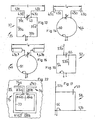
- the electrical equivalent circuit diagram of this capacitive radiator 1 shows FIG. 2 ,
- the equivalent circuit includes a capacitance C E connected in series with a radiation resistance R E.
- Dipole or monopole antennas that predominantly emit an electric field are often used in a truncated form by shortening the radiation arms to a fraction of the optimum length (e.g., 1/10 of a wavelength). Such shortened radiation arms result in a high, capacitive input impedance.
- a typical magnetic emitter (magnetic antenna) 7 is in FIG. 3 shown.
- the magnetic emitter 7 comprises a coil with preferably a single turn 9 and an adjustable capacitor 11 for a frequency tuning and a small coupling loop 13 for a power supply.
- a coaxial cable, not shown, or other high-frequency conductor is connected to the two terminals 14a and 14b of the coupling loop 13 .
- the magnetic radiator works in resonance, ie the exact frequency must be adjusted by means of the capacitor 11 .
- a frequency range results from the maximum and minimum capacitance of the capacitor 11.
- FIG. 4 the electrical equivalent circuit of the magnetic radiator 7 is shown.
- the equivalent circuit diagram shows a parallel resonant circuit consisting of an inductance L, a capacitance C, a radiation resistance R M and a loss resistance R V.
- R V is greater than R M. This reduces the efficiency significantly.
- the narrow working bandwidth of the magnetic radiator 7 is disadvantageous, ie the capacitor 11 must also be readjusted even with small frequency changes.
- the capacitive radiator will be arranged at the periphery of the magnetic radiator.
- a preferred location results in a connection of the capacitive radiator in the region of the capacitor of the magnetic radiator.
- the capacitive radiator is then fed with the RF voltage (high frequency voltage) applied to the capacitor.
- the magnetic emitter makes an impedance matching for the radiation arms of the coupled electric radiator.
- the impedance matching is then dependent on the electrical distance from the Energyeinkopplungsort the magnetic radiator.
- a connection (coupling) of the electric radiator also at other locations of the periphery, mostly consisting of only one turn wire loop of the magnetic radiator, take place.
- the electric radiator i. arrange its radiation arms in the immediate vicinity of the connection point of the capacitor of the magnetic radiator, wherein the concept of immediate proximity is usually dictated by design constraints. It should be noted, however, that a distance from the effective capacitance is at most ⁇ / 16, where ⁇ is the wavelength of the frequency to be radiated. The closer the electric radiation arms are arranged to the capacitor, the better is a coupling to the electric radiator and the smaller geometric dimensions can be selected at the same frequency.
- the radiation arms of the capacitive beam will be arranged lying in mutually parallel planes. These parallel planes can be placed parallel to the plane of the magnetic emitter. All radiation elements can also be arranged in a single plane. As explained below, optimization of a forward / backward ratio can then be achieved by appropriate selection of the geometric dimensions of the magnetic and capacitive radiators, resulting in a directional antenna.
- Antenna 15 shown in one embodiment is a combination of a magnetic radiator with a capacitive radiator.
- the antenna 15 has two capacitive radiation arms 17a and 17b, two spacers 19a and 19b, a capacitor 22 adjustable in its capacitance value , a single circular turn 20 and a power input 21.
- the energy coupling 21 has two connections 23a and 23b .
- One of the ports 23b is preferably earthed here.
- the energy coupling 21 is electrically connected to a location 24 that can be set on the winding 20 .
- the two terminals 23a and 23b are usually connected to a coaxial cable, through which the transmission power is supplied. Concerning an optimal position of the coupling-in location 24 further details are given below.
- the radiation arms 17a and 17b are electrically connected via a spacer 19a and 19b in the vicinity of the capacitor 22 located in the winding 20 with one of its terminals, so that they are supplied with the RF voltage present there.
- One end of each spacer 19a or 19b is electrically connected to the wire loop 20 and the other end is galvanically connected to one end of each radiation arm 17a or 17b at an angle of 90 °.
- the radiation arms 17a and 17b, the spacers 19a and 19b and the wire loop 20 lie here in one and the same plane, wherein the two radiation arms 17a and 17b are aligned with each other.
- FIG. 6 shows an equivalent electrical circuit diagram 25 to the in FIG. 5 antenna shown 15.
- the equivalent circuit 25 includes an inductor L with here only one single winding 20. Further, the equivalent circuit 25, a capacitance C of the capacitor 22, a capacitance C E of the radiating arms 17a and 17b, a radiation resistance R E of the capacitive Emitter, a radiation resistance R M of the magnetic radiator and a loss resistance R V of the entire antenna 15 on.
- the magnetic antenna as a part of this combination ( FIG. 5 ), fulfills a dual function: It emits a magnetic field and at the same time transforms the RF voltage for the capacitive emitter, which emits an electric field.
- FIG. 7 shows a map used for the subsequent estimates, modified, equivalent electrical circuit 27 which has emerged with the subsequent transformations of the in Fi gur 6 depicted equivalent circuit diagram of the 25th
- the elements C E , C, R M and R V have remained the same in the two equivalent circuit diagrams 25 and 27 .
- the resistance R E ' is the transformed into a magnetic part of the antenna 15 radiation resistance R E of the capacitive radiator.
- the capacitive reactance X C is much larger than the radiation resistance R E.
- i 1 / i 2 X C ⁇ e / X C ,
- R E ' is in the in FIG. 7 shown equivalent circuit diagram.
- the current i flows through the transformed radiation resistance R E ' and emits the same electrical power as that in the equivalent circuit diagram in FIG FIG. 6 drawn radiation resistance R E , through which the current i 2 fliest.
- Magnetic power output P M is provided by the magnetic radiator formed by the winding 20 and the capacitor 22 .
- the antenna according to the invention although containing a magnetic radiator, has a higher efficiency W and a larger bandwidth B compared to a "pure" magnetic radiator, as explained below, and can also produce a directional effect with a suitable choice of the antenna geometry.
- the antenna 15 generates in this case a straightening effect (see embodiment).
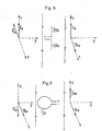
- FIG. 8 shows the electric and magnetic radiation field E K B and K in the far field of a capacitive radiator with radiating arms 29a and 29b, which lie in the paper plane.
- the electric far field to the left and right of the radiation arms 29a and 29b lies in the snapshot shown here in the plane of the paper, with the electric field E K on the left as well as on the right side still pointing up.
- the far-field magnetic vectors B k1 and B K2 generated by the two radiation arms 29a and 29b of the capacitive radiator, are pointing to the left on the paper plane perpendicular to the left (B K1 ) and pointing to the right perpendicular to the paper plane ( B K2 ).
- FIG. 9 shows one too FIG. 8 analogous representation, but for a magnetic radiator whose winding 31 is in the plane of the paper.
- the far-field electric vector E M2 lies upward in the plane of the paper and on the left side of the turn 31 the far-field electric vector E M1 lies down in the plane of the paper.
- the magnetic far field vectors B M of the magnetic radiator are both perpendicular to the paper plane and point to the front.
- the radiation vectors on the right side of the antenna double and on the left side they compensate each other.
- the inventive antenna which is composed of a combination of a magnetic and a capacitive radiator, is a directional antenna.
- the efficiency increases with the length of the capacitive radiators 17a and 17b or 29a and 29b.
- a capacitive connection can be made for example by an insulating bushing. Such a connection is chosen if this is to be potential-free.
- the rotary capacitor 22 may be omitted.
- the resonant frequency is then determined substantially by the capacitance C E of the capacitive radiators 17a and 17b and the capacitance formed by the spacers.
- a slight frequency variation is possible when the capacitance C E is due to a change in the dimensions of the electrical Emitter 17a and 17b or their position is changed. In this case, it is recommended to provide a mechanical adjustment of the capacitive radiator.
- An antenna 35 as a variant of the antenna 15 has a square frame 37 with a side length of 75 cm; gives a circumference of 3 m.
- Each frame side 39a to 39d has an L-shaped aluminum profile, the aluminum having a material thickness of 2 mm and the profile having flanges with dimensions of 50 mm and 30 mm, respectively.
- the frame acts as a single turn of the magnetic sub-antenna.
- a variable capacitor 40 is used analogously to the capacitance 22 .
- the variable capacitor 40 can be set in a capacitance range of 10 pF to 65 pF, whereby the antenna 35 receives an adjustable frequency range of 14 MHz to 30 MHz. For the calculation example, a capacitance value of the rotating capacitor 40 of 65 pF is selected, resulting in a resonance frequency f of 14 MHz.
- the capacitive radiators 41a and 41b analogously to the capacitive radiators 17a and 17b are made of an aluminum profile with a respective length of 1.1 m. This results in a radiator length of 2.2 m.
- the two radiators 41a and 41b were connected next to the rotary capacitor 40 by means of two spacers 43a and 43b (each 15 cm) also made of aluminum.
- the total length l of the capacitive radiators was varied within a range of 0 to 4 m.
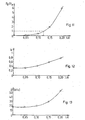
- P E / P M , W, B can be calculated as a function of the length l of the capacitive radiators. l / ⁇ P E / P M W B [kHz] 0 0 0.34 18 0.05 0.03 0.34 18 0.1 0.4 0.41 21 0.15 1.94 0.6 30 0.2 9.06 0.78 55
- FIG. 11 shows the influence of an effective length l of the two capacitive radiators 17a and 17b together relative to the wavelength ⁇ of a resonance frequency of 14 MHz of the antenna 35.
- the ordinate plots the ratio of radiated electrical to radiated magnetic power P E / P M. As might be expected, the value of the power ratio of P E / P M increases disproportionately with the length l of the radiator arms.
- FIGS. 14 and 15 are antenna variants 44 and 46 to the in FIG. 5 shown antenna 15 shown.
- the capacitive radiators denoted here as 45a and 45b or 47a and 47b , can be shortened, as in FIG. 14 indicated at the respective end of the radiator 45a and 45b, an end plate 49a and 49b is arranged.
- this plate 49a or 49b will be circular in shape; but it can also be used a different contour.
- Both plates 49a and 49b are identical. It However, differently shaped plates can be used and thus the lengths of the two capacitive radiators are formed differently long.
- the capacitive radiators 47a and 47b may be as shown in FIG. 15 is hinted at, also in its extent changed, here thickened, become.
- the thickenings will form a circular cylinder.
- other shapes such as plates arranged in a rod longitudinal direction, may be used.
- the capacitive radiators 17a / b, 41a / b, 45a / b and 47a / b in the Figures 5 . 10, 14 and 15 are always outside on the winding 20, 37, 50 and 51 of the magnetic radiator. That does not have to be that way.
- a radiation arm 53a can also, as in a FIG. 16 shown antenna 52, be disposed within a winding 54 of the magnetic radiator.
- a second capacitive radiator 53b is parallel to the radiator 53a.
- the base points of both radiators 53a and 53b lie on both sides of the connection locations of a capacitor 55.
- Magnetic radiators 54 which are shown approximately as a square frame, can also be of circular design. Also, at the free ends of the local capacitive radiators 53a and 53b to the plane of the circle of the magnetic radiator 54 and the antenna parts 53a and 53b perpendicular antenna parts can be arranged.
- the in FIG. 16 downwardly directed antenna part 53a are divided into two or more antenna parts, which are then connected to the same location of the capacitive partial radiator 53a and perpendicular to the antenna part 53b and perpendicular to the plane in which the magnetic radiator 54 is located.
- antennas are each two aligned or parallel capacitive radiator 17a / b, 41a / b, 45a / b, 47a / b and 53a / b available. That too does not have to be. It can also be used with non-parallel capacitive radiators 57a and 57b, as in an antenna variant 58 in FIG FIG. 17 is shown to be worked. This capacitive radiator 57 is also not arranged in the immediate vicinity of a rotary capacitor 59 here .
- the magnetic emitter has a square winding 60. However, this winding can also, as in the Figures 5 . 14 and 15 indicated to be circular.
- FIG. 17 the magnetic emitter has a square winding 60. However, this winding can also, as in the Figures 5 . 14 and 15 indicated to be circular. In FIG.
- the two capacitive radiators 57a and 57b are at an angle of 90 ° to each other.
- This also does not have to be like another antenna variant 62 in FIG. 18 shows, in which two capacitive radiators 61a and 61b have an angle different from 90 ° and from a parallel arrangement with each other.
- the two capacitive radiators 57a and 57b are formed as side extensions of the square winding 60 of the magnetic radiator. These page extensions can now, as with another antenna variant 64 in FIG. 19 is also designed such that the capacitive radiators 63a and 63b are aligned with each other.
- the magnetic and the capacitive radiators lie in one plane. That too does not have to be.
- FIG. 20 is seen from above, ie in the drawing plane of the previous examples from the upper leaf side down, another antenna variant 68 according to the invention shown.
- One turn of the magnetic radiator now appears only as a line 65, wherein the winding parts extending to the rear through the plane of the drawing are marked as arrow ends 66a and 66b for three-dimensional clarification.
- two capacitive radiators 69a and 69b extend in a plane perpendicular to a plane in which the winding 65 of the magnetic radiator lies.
- FIG. 21 A further embodiment of the antenna 70 according to the invention is shown, in which the two capacitive radiators 71a and 71b are arranged in parallel planes to the plane of the magnetic radiator such that the plane of the magnetic radiator 72 lies between the two planes of the capacitive radiator.
- an antenna arrangement 75 is shown for example for resonance frequencies above 300 MHz.
- a square winding 73 and two capacitive radiators 74a and 74b are embodied here as printed circuit traces of a printed circuit 85 .
- the two adjacent supply lines 83a and 83b act here to the two capacitive radiators 74a and 74b.
- an opening 84a or 84b is formed in the printed circuit.
- the two openings 84a and 84b are plug-in connections for a capacitive trimmer for fine adjustment of the resonance frequency f. Power is fed to antenna 75 at port 81a and ground at port 81b .
- the printed antenna can also be coupled with simple electronics.
- the printed antenna would then receive supply energy for the coupled electronics (chip) from a transmitter which is arranged, for example, in the vicinity of a cash register or an outlet of a department store.
- the chip could then be one Create a goods identification signal, which is received and processed by the sender. A scanning of purchased goods at the cash register would thus be omitted; All goods in a shopping cart would be recognized by radio technology without removal and charged.
- connections for the capacitive trimmer need not be designed as breakthroughs; only soldering points can be present.
- the resonant frequency f determining capacity can be generated by a corresponding arrangement of the leads to the radiation arms. Often, however, a fine adjustment of this resonance frequency f is desired. A fine adjustment can now, as described above for the antenna 75 , be made with the soldered capacitive trimmer. More capacitive trimmers are in the Figures 5 . 10, 14, 15, 17 to 21 and 23 indicated.
- antenna 15 shown can be modified such that the rotary capacitor 22 (capacitive trimmer) is removed and the two now resulting free ends 87a and 87b of the coil 20 are connected to an insulating tab (not shown) for mechanical stability.
- On the spacer 19b approximately in its lower third is perpendicular to the extension of the spacer 19b (not shown) plate arranged.
- the distance between the two plates is changed relative to one another, the capacitance value being greater, the larger the plate extension is formed and the smaller is their mutual distance.
- the spacers 19a and 19b may be formed as threaded rods, on which both or only one of the plates can then be changed by turning in the position.
- the capacitance value can also be changed by pivoting the tabs against each other.
- the capacitive radiators should be arranged in the vicinity of the connection locations of the variable capacitor; ie the electrical connection locations (eg spacers) 78a and 78b of the capacitive radiator 79 should be in the vicinity of the foot points 77a and 77b of the rotary capacitor 79 ( FIG. 23 ). However, they can also be arranged at a distance from the foot points 77a and 77b , ie in the region A 1 and A 2 . Preferably will one choose a symmetrical distance? It does not make sense to arrange the connection locations between the energy supply points 80a and 80b ; ie not between the points 24 or 80a and the grounding point 23b or 80b. A shift in the connection locations changes the RF voltage applied to the capacitive radiators. The greater a distance from the points 24 or 80a and 23a or 80b is selected, the greater the impedance value.
- the constructive structures of the antennas 5, 10, 14 to 22 shown above each have a plane of symmetry relating to the at least one capacitive radiator and the at least one magnetic radiator. If such a symmetrical arrangement is selected, then the feed location for the transmission power is voltage-neutral. A voltage neutrality at the feed location should be given so that no so-called mantle waves can arise on an energy supply line. Namely, such cladding waves would change the radiation characteristics, the gain and the quality of the antenna. In addition, this characteristic would also change if changes in the location of the energy supply are made.
- the antenna can no longer be constructed symmetrically due to the environment, because, for example, a downwardly directed antenna part of a capacitive radiator in a design variant analogous to Figures 16 or 20 would touch the ground.
- a downwardly directed antenna part of a capacitive radiator in a design variant analogous to Figures 16 or 20 would touch the ground.
- FIG. 5 illustrated antenna 15 under a task of their symmetry, as in the FIGS. 24 and 25 shown to be formed as a p-shaped antenna 90 , wherein there is no longer an electrically conductive transition between the linear part 91 and abutting him to the circular portion 92 ; there is a gap 93 here.
- ⁇ -shaped is meant a shape according to the Greek letter rho.
- a straight antenna section 94 is arranged perpendicular to the linear part of the " ⁇ "'s. The straight portion 94 together with the linear part 91 forms a capacitance which is adjustable by changing the gap width d .
- the circular portion 92 is the magnetic radiator and the linear and the straight portion 91 and 94 form the capacitive radiator.
- the energy feed 95 takes place at the apex of the circular part 92.
- Such an antenna has a good directivity. It is inexpensive to manufacture and could thus preferably be used in the transmission of information records in ad hoc networks, such as For example, they are used between vehicles (car-to-car) or used in any mobile or portable use.
- a b-shaped design can be made, which is particularly suitable for low frequencies (below 10 MHz).
- a semicircular part in order to increase the mechanical stability to a straight rod or to a flat element, a semicircular part can be welded or soldered.
- the electric radiator as shown schematically in FIG. 1 represented, now also forms a capacity with its radiation arms.
- a capacity resulting from the mechanical construction formed by the radiant arms of the electric radiator can now be determined by using a plurality of radiating arms with and without changes to the arm ends (for example, see the end plates 49a and 49b in FIG FIG. 14 ) be designed such that it corresponds to the predetermined capacity of the magnetic radiator.
- a partial capacity can then be provided.
- an effect of tuning can also be achieved by making geometrical distances between the units forming the electric radiator.
- Such a trained antenna consisting of a combination of at least one magnetic radiator with at least one capacitive radiator is characterized by a compact, raum insomniassig reduced structure, which also usually can also be produced inexpensively.
Landscapes
- Variable-Direction Aerials And Aerial Arrays (AREA)
- Waveguide Aerials (AREA)
- Details Of Aerials (AREA)
Description
- Die Erfindung betrifft eine Antenne, insbesondere eine Sendeantenne.
- In der
DE 88 12 235 U1 sind magnetische Sende- und/oder Empfangsantennen beschrieben. Diese bekannten Antennen haben einen annähernd kreisringförmig gebogenen Ring, dessen Ringenden einen Plattenkondensator aufweisen, wobei eine Einstellung der Kondensatorkapazität über eine Verstellung des Plattenabstandes erfolgt. Bei der Verlängerung einer Kondensatorplatte oder einer teilweise nicht parallelen Weiterführung der Kondensatorplatten ändert sich wesentlich das Strahlungsdiagramm der Antenne. Gleichzeitig kommt zur magnetischen eine elektromagnetische Strahlungskomponente hinzu. - Aus der
WO00/25385 A1 - Aufgabe der Erfindung ist es, eine Antenne, insbesondere eine Sendeantenne, mit einem guten Wirkungsgrad bei kleinen geometrischen Abmessungen zu schaffen.
- Diese Aufgabe wird durch die Merkmale von Patentanspruch 1 gelöst. Bevorzugte Ausführungsvarianten sind durch die Merkmale der abhängigen Patentansprüche definiert.
- Ein typischer kapazitiver Strahler (kapazitive Antenne) 1 ist in
Figur 1 dargestellt. Der kapazitive Strahler 1 hat zwei Strahlungsarme 3a und 3b und zwei zu den Strahlungsarmen 3a und 3b führende Abstandshalter 5a und 5b. Eine Energieeinspeisung erfolgt an den Anschlüssen 6a und 6b an den den Strahlungsarmen 3a und 3b abgewandten Enden der Abstandshalter 5a und 5b. Das elektrische Ersatzschaltbild dieses kapazitiven Strahlers 1 zeigtFigur 2 . Das Ersatzschaltbild beinhaltet eine mit einem Strahlungswiderstand RE in Reihe geschaltete Kapazitat CE . - Dipol- oder Monopolantennen, die vorwiegend ein elektrisches Feld abstrahlen, werden oft in einer verkürzten Form verwendet, indem die Strahlungsarme auf einen Bruchteil der optimalen Länge verkürzt werden (z.B. auf 1/10 der Wellenlänge). Derart verkürzte Strahlungsarme ergeben eine hohe, kapazitive Eingangsimpedanz.
- Die Anpassung kapazitiver Strahler an ein übliches 50 Ohm-Koaxialkabel erfordert ein nicht dargestelltes Anpassnetzwerk, das meist aus Spulen und Kondensatoren besteht. Da Spulen nicht verlustfrei hergestellt werden können, erniedrigt sich der Wirkungsgrad durch Wärmeverluste in den Spulen zum Teil erheblich.
- Ein typischer magnetischer Strahler (magnetische Antenne) 7 ist in
Figur 3 dargestellt. Der magnetische Strahler 7 weist eine Spule mit vorzugsweise einer einzigen Windung 9 und einem einstellbaren Kondensator 11 für eine Frequenzabstimmung sowie eine kleine Einkoppelschlaufe 13 für eine Energiezufuhr auf. An die beiden Anschlüsse 14a und 14b der Einkoppelschlaufe 13 wird ein nicht dargestelltes Koaxialkabel oder ein sonstiger Hochfrequenzleiter angeschlossen. Der magnetische Strahler arbeitet in Resonanz, d.h. die exakte Frequenz muss mittels des Kondensators 11 eingestellt werden. Ein Frequenzbereich ergibt sich aus der Maximal- und Minimalkapazität des Kondensators 11. - In
Figur 4 ist das elektrische Ersatzschaltbild des magnetischen Strahlers 7 dargestellt. Das Ersatzschaltbild zeigt einen Parallelschwingkreis, der aus einer Induktivität L, einer Kapazität C, einem Strahlungswiderstand RM und einem Verlustwiderstand RV besteht. In vielen Fällen ist RV grösser als RM. Hierdurch reduziert sich der Wirkungsgrad erheblich. Für viele Anwendungen ist zudem die schmale Arbeitsbandbreite des magnetischen Strahlers 7 nachteilig, d.h. der Kondensator 11 muss auch bereits bei kleinen Frequenzänderungen nachgestellt werden. - Wie bereits oben ausgeführt ist, wird nun erfindungsgemäss eine Kombination eines magnetischen Strahlers mit einem kapazitiven Strahler vorgenommen.
- Vorzugsweise wird man den kapazitiven Strahler an der Peripherie des magnetischen Strahlers anordnen. Ein bevorzugter Ort ergibt sich, bei einem Anschluss des kapazitiven Strahlers im Bereich des Kondensators des magnetischen Strahlers. Der kapazitive Strahler wird dann mit der jeweils am Kondensator anliegenden HF-Spannung (Hochfrequenzspannung) gespeist. Vereinfacht ausgedrückt, macht der magnetische Strahler eine Impedanzanpassung für die Strahlungsarme des angekoppelten elektrischen Strahlers. Die Impedanzanpassung ist dann abhängig von der elektrischen Distanz vom Energieeinkopplungsort am magnetischen Strahler. Selbstverständlich kann ein Anschluss (Ankopplung) des elektrischen Strahlers auch an anderen Orten der Peripherie, der meistens nur aus einer Windung bestehenden Drahtschlaufe des magnetischen Strahlers, erfolgen.
- Vorzugsweise wird man den elektrischen Strahler, d.h. seine Strahlungsarme in unmittelbarer Nähe zum Anschlusspunkt des Kondensators des magnetischen Strahlers anordnen, wobei der Begriff der unmittelbaren Nähe in der Regel durch konstruktive Zwänge vorgegeben ist. Man sollte jedoch darauf achten, dass ein Abstand von der wirksamen Kapazität höchstens λ/16 entfernt ist, wobei λ die Wellenlänge der abzustrahlenden Frequenz ist. Je näher die elektrischen Strahlungsarme am Kondensator angeordnet werden, desto besser ist eine Kopplung zum elektrischen Strahler und desto kleiner können geometrische Abmessungen bei gleicher Frequenz gewählt werden.
- Vorzugsweise wird man die Strahlungsarme des kapazitiven Strahles in zueinander parallelen Ebenen liegend anordnen. Diese parallelen Ebenen kann man parallel zur Ebene des magnetischen Strahlers legen. Es können auch alle Strahlungselemente in einer einzigen Ebene angeordnet werden. Wie unten ausgeführt, kann dann durch eine entsprechende Auswahl der geometrischen Abmessungen des magnetischen und des kapazitiven Strahlers eine Optimierung eines Vor-/Rückwärtsverhältnisses erreicht werden, wodurch sich eine Richtantenne ergibt.
- Durch eine kapazitive Belastung der Strahlungsarmenden (Endkapazitäten) kann zudem eine Verkürzung der Strahlungsarme erreicht werden.
- Weitere Vorteile und Ausführungsvarianten der erfindungsgemässen Antenne ergeben sich aus der nachfolgenden Detailbeschreibung.
- Die zur Erläuterung der Ausführungsbeispiele verwendeten Zeichnungen zeigen in
- Fig. 1
- einen typischen kapazitiven Strahler,
- Fig. 2
- ein elektrisches Ersatzschaltbild des in
Figur 1 dargestellten kapazitiven Strahlers, - Fig: 3
- einen typischen magnetischen Strahler,
- Fig. 4
- ein elektrisches Ersatzschaltbild des in
Figur 3 dargestellten magnetischen Strahlers, - Fig. 5
- eine Ausführungsform einer Antenne,
- Fig. 6
- ein elektrisches Ersatzschaltbild zu der in
Figur 5 gezeigten Antenne, - Fig. 7
- ein zum Ersatzschaltbild in
Figur 6 modifiziertes, elektrisches Ersatzschaltbild, - Fig. 8
- ein Strahlungsfeld im Fernfeld links und rechts eines kapazitiven Strahlers mit dem in der Papierebene liegenden Strahlungsarmen 29a und 29b in perspektivischer Darstellung mit den elektrischen Feldvektoren EK (in der Papierebene) und den magnetischen Feldvektoren BK1 und BK2 (senkrecht nach vorne und nach hinten zur Papierebene stehend),
- Fig. 9
- ein Strahlungsfeld im Fernfeld links und rechts eines magnetischen Strahlers, dessen Windung in der Papierebene liegt, in perspektivischer Darstellung mit den elektrischen Feldvektoren EM1 und EM2 in der Papierebene sowie den magnetischen Feldvektor BM senkrecht aus der Papierebene nach vorne stehend,
- Fig. 10
- ein Ausführungsbeispiel zu der in
Figur 5 erklärten Antenne, - Fig. 11
- ein Diagramm für ein Leistungsverhältnis PE / PM von abgestrahlter elektrischer PE zu magnetischer Leistung PM in Abhängigkeit von einer auf die Wellenlänge λ normierten wirksamen Länge ℓ der beiden kapazitiven Strahler bei einer Antennenresonanzfrequenz vom 14 MHz, gemäss Ausführungsbeispiel,
- Fig. 12
- ein Diagramm für einen Antennenwirkungsgrad W über einer normierten Strahlerlänge ℓ/λ einer auch dem Diagramm in
Figur 11 zugrunde gelegten Antenne, - Fig. 13
- ein Diagramm für eine Bandbreite B in Kilohertz über einer normierten Strahlerlänge ℓ / λ einer auch dem Diagramm in
Figur 11 zugrunde gelegten Antenne, - Fig. 14
- eine Variante des kapazitiven Strahlers einer in
Figur 5 dargestellten Antenne, - Fig. 15
- eine weitere Variante zu der in
Figur 14 dargestellten Antenne, - Fig. 16
- eine weitere Antennenvariante mit gegenüber
Figur 10 anders angeordneten kapazitiven Strahlern, - Fig. 17
- eine Antennenvariante zu der in
Figur 16 gezeigten Antenne mit kapazitiven Strahlern, welche einen Winkel von 90° miteinander einschliessen, - Fig. 18
- eine Antennenvariante zu der in
Figur 5 dargestellten Antenne, wobei die beiden kapazitiven Strahler weder parallel zueinander angeordnet sind, noch miteinander fluchten, - Fig. 19
- eine Antennenvariante zu der in
Figur 17 dargestellten Antenne, wobei die beiden kapazitiven Strahler als Seitenverlängerung einer quadratischen Windung des magnetischen Strahlers ausgebildet sind und miteinander fluchten, - Fig. 20
- eine Ausführungsvariante zur Antennendarstellung in
Figur 16 , wobei die beiden kapazitiven Strahler in einer Ebene senkrecht zur Ebene des magnetischen Strahlers liegen, - Fig. 21
- eine Ausführungsvariante zur Antennendarstellung in
Figur 16 , wobei jeder kapazitive Strahler in einer voneinander distanzierten parallelen Ebene liegt, zu denen mittig der magnetische Strahler angeordnet ist, - Fig. 22
- eine Antennenausführungsvariante für eine Antennenanordnung als sogenannte gedruckte Schaltung,
- Fig. 23
- eine Skizze, in der mögliche Anschlussorte eines kapazitiven Strahlers an einen magnetischen Strahler aufgezeigt werden,
- Fig. 24
- eine schematische Darstellung einer p-förmig ausgebildeten Antenne und
- Fig. 25
- eine Ansicht in Blickrichtung XXV der in
Figur 24 dargestellten Antenne in technischer Ausführung. - Die in
Figur 5 in einer Ausführungsform dargestellteAntenne 15 ist eine Kombination eines magnetischen Strahlers mit einem kapazitiven Strahler. Die Antenne 15 hat zwei kapazitiv wirkende Strahlungsarme 17a und 17b, zwei Abstandshalter 19a und 19b, einen in seinem Kapazitätswert einstellbaren Kondensator 22, eine einzige kreisförmig gebogene Windung 20 und eine Energieeinkopplung 21. Die Energieeinkopplung 21 weist zwei Anschlüsse 23a und 23b auf. Einer der Anschlüsse 23b ist hier vorzugsweise geerdet. Die Energieeinkopplung 21 ist an einem in der Lage auf der Windung 20 einstellbaren Ort 24 mit dieser elektrisch verbunden. Die beiden Anschlüsse 23a und 23b werden in der Regel an ein Koaxialkabel angeschlossen, durch das die Sendeleistung zugeführt wird. Betreffend einer optimalen Lage des Einkoppelorts 24 werden unten weitere Angaben gemacht. - Die Strahlungsarme 17a und 17b sind über einen Abstandshalter 19a und 19b in der Nähe des in der Windung 20 liegenden Kondensators 22 mit je einem dessen Anschlusses elektrisch verbunden, so dass sie mit der dort vorhandenen HF-Spannung gespeist werden. Ein Ende jedes Abstandshalters 19a bzw. 19b ist elektrisch mit der Drahtschlaufe 20 und das jeweils andere Ende mit einem Ende je eines Strahlungsarms 17a bzw. 17b unter einem Winkel von 90° galvanisch verbunden. Die Strahlungsarme 17a und 17b, die Abstandshalter 19a und 19b und die Drahtschlaufe 20 liegen hier in ein- und derselben Ebene, wobei die beiden Strahlungsarme 17a und 17b miteinander fluchten.
-
Figur 6 zeigt ein elektrisches Ersatzschaltbild 25 zu der inFigur 5 gezeigten Antenne 15. Das Ersatzschaltbild 25 beinhaltet eine Induktivität L mit hier lediglich einer einzigen Windung 20. Ferner weist das Ersatzschaltbild 25 eine Kapazität C des Kondensators 22, eine Kapazität CE der Strahlungsarme 17a und 17b, einen Strahlungswiderstand RE des kapazitiven Strahlers, einen Strahlungswiderstand RM des magnetischen Strahlers und einen Verlustwiderstand RV der gesamten Antenne 15 auf. Die magnetische Antenne, als ein Teil dieser Kombination (Figur 5 ), erfüllt eine Doppelfunktion: Sie strahlt ein magnetisches Feld ab und gleichzeitig transformiert sie die HF-Spannung für den kapazitiven Strahler, welcher ein elektrisches Feld abstrahlt. -
Figur 7 zeigt ein für die nachfolgenden Abschätzungen verwendetes, modifiziertes, elektrisches Ersatzschaltbild 27, welches mit den nachfolgenden Umformungen aus dem in Figur 6 dargestellten Ersatzschaltbild 25 hervorgegangen ist. Die Elemente CE, C, RM und RV sind in den beiden Ersatzschaltbildern 25 und 27 gleich geblieben. Der Widerstand RE' ist der in einen magnetischen Teil der Antenne 15 transformierte Strahlungswiderstand RE des kapazitiven Strahlers. - Ein Strom i im magnetischen Kreis der Antenne 15 wird gemäss dem Ersatzschaltbild 25 in
Figur 6 aufgeteilt in die beiden Teilströme i1 und i2
- Ein kapazitive Blindwiderstand XC des Kondensators 26 mit der Kapazität C ergibt sich bei einer Resonanzfrequenz f zu

- Ein kapazitiver Blindwiderstand XCE des kapazitiven Strahlers mit den Strahlungsarmen 17a und 17b mit der Kapazität CE ergibt sich bei der Resonanzfrequenz f zu

- Für den im Kondensator 26 fliessenden Strom i1 gilt bei einer über dem Kondensator 26 liegenden Spannung u

- Bei einem kapazitiven Strahler mit in einer Ausführungsvariante kurzen Strahlungsarmen 17a und 17b ist der kapazitive Blindwiderstand XC viel grösser als der Strahlungswiderstand RE.
- Für den Strom i2 im kapazitiven Strahler gilt näherungsweise

- Mit einer Division der obigen Gleichungen für die Ströme i1 und i2 lässt sich die Spannung u eliminieren:

- Wird der Strom i1 unter Verwendung von Gleichung (1) in Gleichung (2) eliminiert, so ergibt sich für den Strom i2

- Daraus ergibt sich eine abgestrahlte elektrische Leistung PE durch den kapazitiven Strahler zu

oder
- RE' ist in dem in
Figur 7 dargestellten Ersatzschaltbild eingezeichnet. Der Strom i durchfliesst den transformierten Strahlungswiderstand RE' und strahlt die gleiche elektrische Leistung ab wie der im Ersatzschaltbild inFigur 6 eingezeichnete Strahlungswiderstand RE, durch den der Strom i2 fliest. - Eine magnetische Leistungsabstrahlung PM erfolgt durch den magnetischen Strahler, gebildet aus der Windung 20 und dem Kondensator 22.
- Bezüglich der abgestrahlten elektrischen Leistung PE im Verhältnis zur abgestrahlten magnetischen Leistung PM gilt

- Die erfindungsgemässe Antenne, obwohl sie einen magnetischen Strahler enthält, hat gegenüber einem "reinen" magnetischen Strahler, wie unten ausgeführt wird, einen höheren Wirkungsgrad W und eine grössere Bandbreite B und kann bei geeigneter Wahl der Antennengeometrie zudem einen Richteffekt erzeugen. Das Verhältnis PE / PM steigt mit der Länge L des kapazitiven Strahlers an. Bei einer bestimmten Länge L des kapazitiven Strahlers wird RE' = RM, dann wird PE/PM = 1, d.h. die magnetisch abgestrahlte Leistung PM ist gleich gross wie die elektrisch abgestrahlte Leistung PE. Die Antenne 15 erzeugt in diesem Fall einen Richteffekt (siehe Ausführungsbeispiel).
- Der Richteffekt der Antenne 15 wird an Hand der
Figuren 8 und 9 erläutert. DieFigur 8 zeigt das elektrische und das magnetische Strahlungsfeld EK und BK im Fernfeld eines kapazitiven Strahlers mit den Strahlungsarmen 29a und 29b, welche in der Papierebene liegen. Das elektrische Fernfeld links und rechts der Strahlungsarme 29a und 29b liegt in der hier gezeigten Momentaufnahme in der Papierebene, wobei das elektrische Feld EK auf der linken wie auch auf der rechten Seite noch oben zeigt. Die magnetischen Fernfeldvektoren Bk1 und BK2, erzeugt durch die beiden Strahlungsarme 29a und 29b des kapazitiven Strahlers, stehen auf deren linken Seite senkrecht auf der Papierebene nach hinten zeigend (BK1) und auf der rechten Seite senkrecht auf der Papierebene nach vorne zeigend (BK2). -
Figur 9 zeigt eine zuFigur 8 analoge Darstellung, jedoch für einen magnetischen Strahler, dessen Windung 31 in der Papierebene liegt. Rechts der Windung 31 zeigt der elektrische Fernfeldvektor EM2 in der Papierebene liegend nach oben und auf der linken Seite der Windung 31 zeigt der elektrische Fernfeldvektor EM1 in der Papierebene liegend nach unten. - Die magnetischen Fernfeldvektoren BM des magnetischen Strahlers stehen beide auf der Papierebene senkrecht und zeigen nach vorne.
- Da hier nun ein elektrischer und ein magnetischer Strahler zusammen arbeiten, ist eine Überlagerung der in den
Figuren 8 und 9 gezeigten Fernfeldvektoren vorzunehmen: - Auf der linken Seite des elektrischen und des magnetischen Strahlers gilt nun für die Fernfeldstärke
EK - EM1 und BK1 - BM
und auf der rechten Seite des elektrischen und des magnetischen Strahlers gilt nun für die Fernfeldstärke
EK + EM2 und BK2 + BM. - In einem Spezialfall, bei dem kapazitiver und magnetischer Strahler dieselbe Leistung abstrahlen, verdoppeln sich die Strahlungsvektoren auf der rechten Seite der Antenne (y-Richtung in der Papierebene) und auf der linken Seite kompensieren sie sich.
- Die erfindungsgemässe Antenne, welche aus einer Kombination eines magnetischen und eines kapazitiven Strahlers zusammengesetzt ist, ist eine Richtungsantenne.
- Der Wirkungsgrad W ergibt sich zu

- Der Wirkungsgrad steigt mit der Länge der kapazitiven Strahler 17a und 17b bzw. 29a und 29b an.
- Die Bandbreite B ergibt sich aus einer Kreisgüte Q gemäss der nachfolgenden Beziehung

- Falls XCE >> XC kann die Kreisgüte Q näherungsweise berechnet werden mit

- Damit ergibt die Bandbreite B zu

- Erweitert mit (RM + RV) und umgeformt ergibt sich

oder
mit
wobei B0 die Bandbreite der rein magnetischen Antenne ohne die kapazitiven Strahler ist. Die Bandbreite B vergrössert sich mit der Länge der kapazitiven Strahler. - Anstelle der galvanischen Verbindung, wie oben ausgeführt, der Drahtschlaufe 20 mit den beiden kapazitiv wirkenden Strahlungsarmen 17a und 17b über die Abstandshalter 19a und 19b kann auch eine kapazitive Verbindung z.B. durch eine isolierende Durchführung vorgenommen werden. Eine derartige Verbindung wird gewählt, wenn diese potentialfrei sein soll.
- Falls die Antenne 15 nur für ein schmales Frequenzband verwendet werden soll, kann beispielsweise der Drehkondensator 22 weggelassen werden. Die Resonanzfrequenz wird dann massgeblich durch die Kapazität CE der kapazitiven Strahler 17a und 17b und der durch die Abstandshalter gebildeten Kapazität bestimmt. Eine geringfügige Frequenzvariation ist möglich, wenn die Kapazität CE durch eine Änderung der Abmessungen der elektrischen Strahler 17a und 17b oder deren Position verändert wird. In diesem Falle empfiehlt es sich, eine mechanische Justierung der kapazitiven Strahler vorzusehen.
- Eine Untermauerung obiger Ausführungen wird mit dem nachfolgenden Ausführungsbeispiel vorgenommen. Eine Antenne 35 als Ausführungsvariante zur Antenne 15 hat einen quadratischen Rahmen 37 mit einer Seitenlänge von 75 cm; ergibt einen Umfang von 3 m. Jede Rahmenseite 39a bis 39d hat ein L-förmiges Aluminiumprofil, wobei das Aluminium eine Materialdicke von 2 mm und das Profil Flansche mit den Abmessungen von 50 mm bzw. 30 mm hat. Der Rahmen wirkt als eine einzige Windung der magnetischen Teilantenne. Im Rahmen 37 ist analog zur Kapazität 22 ein Drehkondensator 40 eingesetzt. Der Drehkondensator 40 kann in einem Kapazitätsbereich von 10 pF bis 65 pF eingestellt werden, wodurch die Antenne 35 einen einstellbaren Frequenzbereich von 14 MHz bis 30 MHz erhält. Für das Berechnungsbeispiel wird ein Kapazitätswert des Drehkondensators 40 von 65 pF gewählt, wodurch sich eine Resonanzfrequenz f vom 14 MHz ergibt.
- Die kapazitiven Strahler 41a und 41 b analog zu den kapazitiven Strahlern 17a und 17b sind aus einem Aluminiumprofil mit einer jeweiligen Länge von 1,1 m hergestellt. Hieraus ergibt sich eine Strahlerlänge von 2,2 m. Die beiden Strahler 41a und 41b wurden neben dem Drehkondensator 40 mittels zweier Abstandshalter 43a und 43b (jeder 15 cm) ebenfalls aus Aluminium angeschlossen. Ein Verlustwiderstand RV dieser Antenne 35 ist aus der Messung der Bandbreite B0 der rein magnetischen Antenne (Rahmen 37 mit Drehkondensator 40, ohne die beiden kapazitiven Strahler 41a und 41b) auf RV = 0,15 Ω bestimmt worden. Für die Darstellung in den Diagrammen wurde die Gesamtlänge ℓ der kapazitiven Strahler in einem Bereich von 0 bis 4 m variiert.
- Der Strahlungswiderstand RE des kapazitiven Strahlers, der Strahlungswiderstand RM des magnetischen Strahlers und der kapazitive Blindwiderstand XCE des kapazitiven Strahlers lassen sich mittels bekannter Formeln der Antennentechnik wie folgt berechnen (siehe beispielsweise Rothammel, Antennenbuch, DARC-Verlag, 12. Auflage, Seiten 73, 333 und 429-431):


- Mittels der Formeln (3), (4), (5) und (6) lassen sich PE/PM, W, B in Abhängigkeit von der Länge ℓ der kapazitiven Strahler berechnen.
ℓ/λ PE/PM W B [kHz] 0 0 0,34 18 0,05 0,03 0,34 18 0,1 0,4 0,41 21 0,15 1,94 0,6 30 0,2 9,06 0,78 55 - Die Ergebnisse der Berechnungen sind in den Diagrammen der
Figuren 11, 12 und 13 grafisch dargestellt. -
Figur 11 zeigt den Einfluss einer wirksamen Länge ℓ der beiden kapazitiven Strahler 17a und 17b zusammen bezogen auf die Wellenlänge λ einer Resonanzfrequenz vom 14 MHz der Antenne 35. Auf der Ordinate ist das Verhältnis von abgestrahlter elektrischer zu abgestrahlter magnetischer Leistung PE / PM aufgetragen. Wie zu erwarten war, steigt der Wert des Leistungsverhältnisses von PE / PM überproportional mit der Länge ℓ der Strahlerarme. -
Figur 11 kann wie folgt interpretiert werden: Falls die kapazitiven Strahler 17a und 17b die Länge null haben, wird nur magnetische Leistung abgestrahlt (PE = 0). Je länger die kapazitiven Strahler 17a und 17b im Vergleich zur Wellenlänge λ ausgelegt werden, desto höher wird der Anteil der elektrisch abgestrahlten Leistung PE. Ist PE / PM =1, so wird gleich viel elektrische wie magnetische Leistung abgestrahlt; das ist bei einer Länge ℓ/λ = 0,124 (gestrichelte Linie inFigur 11 ) der Fall. Bei dieser Strahlerlänge erzeugt die Antenne eine optimale Richtwirkung (maximale Richtwirkung). Die angefertigte Antenne erfüllte annähernd diese Bedingung. Messungen ergaben ein Vor-/Rückwärtsverhältnis von ca. 12 db. - Der Wirkungsgrad W und die Bandbreite B in Kilohertz einer oben beschriebenen Antenne 35 in Abhängigkeit von einer auch hier auf die Wellenlänge λ genormte Strahlerlänge ℓ/λ ist in
Figur 12 bzw. 13 dargestellt. Beide Kurven steigen über der Länge ℓ überproportional. - In den
Figuren 14 und 15 sind Antennenvarianten 44 und 46 zu der inFigur 5 dargestellten Antenne 15 gezeigt. Die kapazitiven Strahler, hier mit 45a und 45b bzw. 47a und 47b bezeichnet, können verkürzt werden, in dem wie inFigur 14 angedeutet, am jeweiligen Ende des Strahlers 45a bzw. 45b eine Endplatte 49a bzw. 49b angeordnet ist. Vorzugsweise wird man diese Platte 49a bzw. 49b kreisförmig ausbilden; es kann aber auch eine andere Kontur verwendet werden. InFigur 14 sind beide Platten 49a und 49b identisch ausgebildet. Es können jedoch auch unterschiedlich ausgebildete Platten verwendet werden und somit die Längen der beiden kapazitiven Strahler unterschiedlich lang ausgebildet sein. - Anstelle der Endplatten 49a und 49b können die kapazitiven Strahler 47a und 47b, wie in
Figur 15 angedeutet ist, auch in ihrem Umfang verändert, hier verdickt, werden. Vorzugsweise wird man die Verdickungen kreiszylindrisch ausbilden. Es können jedoch auch andere Formen, wie beispielsweise in Stablängsrichtung angeordnete Platten, verwendet werden. - Die kapazitiven Strahler 17a/b, 41a/b, 45a/b und 47a/b in den
Figuren 5 ,10, 14 und 15 befinden sich immer aussen an der Windung 20, 37, 50 und 51 des magnetischen Strahlers. Das muss aber nicht so sein. Ein Strahlungsarm 53a kann auch, wie bei einer inFigur 16 dargestellten Antenne 52, innerhalb einer Windung 54 des magnetischen Strahlers angeordnet sein. Ein zweiter kapazitiver Strahler 53b verläuft parallel zum Strahler 53a. Die Fusspunkte beider Strahler 53a und 53b liegen beidseits der Anschlussorte eines Kondensators 55. - Der in
Figur 16 annähernd als quadratischer Rahmen dargestellte magnetische Strahler 54 kann auch kreisförmig ausgebildet sein. Auch können an den freien Enden der dortigen kapazitiven Strahler 53a und 53b zur Ebene des Kreises des magnetischen Strahlers 54 und den Antennenteilen 53a und 53b senkrecht verlaufende Antennenteile angeordnet werden. - Aus Platzgründen kann auch der in
Figur 16 nach unten gerichtete Antennenteil 53a in zwei oder mehrere Antennenteile aufgeteilt werden, welche dann am selben Ort des kapazitiven Teilstrahlers 53a angeschlossen werden und senkrecht zum Antennenteil 53b und senkrecht zur Ebene verlaufen, in der der magnetische Strahler 54 liegt. - In den
Figuren 5 ,10, und 14 bis 16 skizzierten Antennen sind jeweils zwei fluchtende oder parallel zueinander liegende kapazitive Strahler 17a/b, 41a/b, 45a/b, 47a/b und 53a/b vorhanden. Auch das muss nicht sein. Es kann auch mit nicht parallelen kapazitiven Strahlern 57a und 57b, wie in einer Antennenvariante 58 inFigur 17 dargestellt ist, gearbeitet werden. Dieser kapazitive Strahler 57 ist hier zudem nicht in unmittelbarer Nähe eines Drehkondensators 59 angeordnet. InFigur 17 hat der magnetische Strahler eine quadratische Windung 60. Diese Windung kann jedoch auch, wie in denFiguren 5 ,14 und 15 angedeutet, kreisförmig sein. InFigur 17 stehen die beiden kapazitiven Strahler 57a und 57b unter einem Winkel von 90° zueinander. Auch dies muss nicht sein, wie eine weitere Antennenvariante 62 inFigur 18 zeigt, in der zwei kapazitive Strahler 61a und 61b einen von 90° und von einer parallelen bzw. fluchtenden Anordnung abweichenden Winkel miteinander haben. - In
Figur 17 sind die beiden kapazitiven Strahler 57a und 57b als Seitenverlängerungen der quadratischen Windung 60 des magnetischen Strahlers ausgebildet. Diese Seitenverlängerungen können nun, wie anhand einer weiteren Antennenvariante 64 inFigur 19 dargestellt ist, auch derart ausgebildet sein, dass die kapazitiven Strahler 63a und 63b miteinander fluchten. - In den bisher dargestellten Ausführungsbeispielen liegen der magnetische und der kapazitive Strahler in einer Ebene. Auch das muss nicht sein. In
Figur 20 ist mit Blickrichtung von oben, also in der Zeichnungsebene der vorgängigen Beispiele von der oberen Blattseite nach unten, eine weitere erfindungsgemäße Antennenvariante 68 dargestellt. Eine Windung des magnetischen Strahlers erscheint nun lediglich als Strich 65, wobei die durch die Zeichnungsebene nach hinten verlaufenden Windungsteile zur dreidimensionalen Verdeutlichung als Pfeilende 66a und 66b gekennzeichnet sind. Neben einem Drehkondensator 67 verlaufen hier zwei kapazitive Strahler 69a und 69b in einer Ebene senkrecht zu einer Ebene in der die Windung 65 des magnetischen Strahlers liegt. - In
Figur 21 ist eine weitere erfindungsgemäße Antennenausführungsvariante 70 gezeigt, bei der die beiden kapazitiven Strahler 71a und 71b in parallelen Ebenen zur Ebene des magnetischen Strahlers derart angeordnet sind, dass die Ebene des magnetischen Strahlers 72 zwischen den beiden Ebenen der kapazitiven Strahler liegt. - In
Figur 22 ist eine Antennenanordnung 75 für beispielsweise Resonanzfrequenzen oberhalb 300 MHz dargestellt. Eine quadratische Windung 73 und zwei kapazitive Strahler 74a und 74b sind hier als Leiterbahnen einer gedruckten Schaltung 85 ausgeführt. Als Kapazität 76 wirken hier die beiden benachbarten Zuleitungen 83a und 83b zu den zwei kapazitiven Strahlern 74a und 74b. Bei jedem Übergang einer Zuleitung 83a bzw. 83b in die quadratische Windung 73 des magnetischen Strahles ist ein Durchbruch 84a bzw. 84b in der gedruckten Schaltung ausgebildet. Die beiden Durchbrüche 84a und 84b sind Steckanschlüsse für einen kapazitiven Trimmer zur Feinabgleichung der Resonanzfrequenz f. Eine Energieeinspeisung in die Antenne 75 erfolgt am Anschluss 81a und eine Erdung am Anschluss 81b. - Anwendungsgebiete einer analog zur in
Figur 22 ausgebildeten Antenne 75, sofern diese Antenne auf eine Folie gedruckt wird, sind beispielsweise ein Diebstahlschutz von Verkaufsgegenständen, welche diese preisgünstig herzustellende Antenne tragen. Die gedruckte Antenne kann zudem mit einer einfachen Elektronik gekoppelt werden. Über die aufgedruckte Antenne würde dann von einem Sender, welcher beispielsweise in der Nähe einer Registrierkasse oder eines Ausgangs eines Warenhauses angeordnet ist, Versorgungsenergie für die angekoppelte Elektronik (Chip) empfangen. Der Chip könnte dann ein Warenidentifizierungssignal kreieren, welches vom Sender empfangen und verarbeitet wird. Ein Abscannen eingekaufter Waren an der Kasse würde somit entfallen; sämtliche Waren in einem Warenkorb würden ohne ein Herausnehmen funktechnisch erkannt und verrechnet werden. - Die Anschlüsse für den kapazitiven Trimmer müssen nicht als Durchbrüche ausgebildet sein; es können lediglich Lötpunkte vorhanden sein.
- Die die Resonanzfrequenz f bestimmende Kapazität kann durch eine entsprechende Anordnung der Zuleitungen zu den Strahlungsarmen erzeugt werden. Oftmals ist jedoch ein Feinabgleich dieser Resonanzfrequenz f gewünscht. Ein Feinabgleich kann nun, wie oben bei der Antenne 75 beschrieben, mit dem eingelöteten kapazitiven Trimmer vorgenommen werden. Weitere kapazitive Trimmer sind in den
Figuren 5 ,10, 14, 15, 17 bis 21 und 23 angedeutet. - Die in
Figur 5 dargestellte Antenne 15 kann jedoch derart abgeändert werden, dass der Drehkondensator 22 (kapazitiver Trimmer) entfernt wird und die beiden nun entstehenden freien Enden 87a und 87b der Windung 20 zur mechanischen Stabilität mit einer isolierenden (nicht dargestellten) Lasche verbunden werden. Auf dem Abstandshalter 19b etwa in dessen unterem Drittel wird senkrecht zur Ausdehnung des Abstandshalters 19b eine (nicht dargestellte) Platte angeordnet. Auf dem Abstandshalter 19a wird eine weitere (ebenfalls nicht dargestellte), entlang des Abstandshalters verstellbare Platte angeordnet, wobei diese Platte über die Platte auf den Abstandshalter 19b greift. Zur Feinabstimmung der Resonanzfrequenz f wird nun der Abstand der beiden Platten gegeneinander verändert, wobei der Kapazitätswert um so grösser ist, je grösser die Plattenausdehnung ausgebildet sind und je kleiner deren gegenseitiger Abstand ist. Es kann nun eine der Platten auf dem betreffenden Abstandshalter fixiert sein, während die andere auf ihrem Abstandshalter verschiebbar, über eine Klemmhalterung fixierbar ausgebildet ist. Sofern die Resonanzfrequenz f nicht allzu hoch gewählt ist, können die Abstandshalter 19a und 19b als Gewindestangen ausgebildet sein, auf denen dann beide oder nur einer der Platten durch Verdrehen in der Lage veränderbar ist bzw. sind. - Bildet man die Platten als Laschen aus, so kann der Kapazitätswert auch durch ein gegeneinander Verschwenken der Laschen verändert werden.
- Die kapazitiven Strahler sollten in der Nähe der Anschlussorte des Drehkondensators angeordnet sein; d.h. die elektrischen Anschlussorte (z.B. Abstandshalter) 78a und 78b des kapazitiven Strahlers 79 sollten in der Nähe der Fusspunkte 77a und 77b des Drehkondensators 79 liegen (
Figur 23 ). Sie können jedoch auch in einem Abstand von den Fusspunkten 77a und 77b entfernt, also im Bereich A1 und A2 angeordnet werden. Vorzugsweise wird man einen symmetrischen Abstand wählen Es ist nicht sinnvoll die Anschlussorte zwischen den Energieeinspeisungspunkten 80a und 80b anzuordnen; also nicht zwischen den Punkten 24 bzw. 80a und dem Erdungspunkt 23b bzw 80b. Eine Verschiebung der Anschlussorte verändert die an den kapazitiven Strahlern liegende HF-Spannung. Je grösser ein Abstand von den Punkten 24 bzw. 80a und 23a bzw. 80b gewählt ist, desto grösser ist der lmpedanzwert. - Die konstruktiven Aufbauten der oben dargestellten Antennen 5, 10, 14 bis 22 haben jeweils eine Symmetrieebene betreffend den wenigstens einen kapazitiven Strahler und den wenigstens einen magnetischen Strahler. Wird eine derartige symmetrische Anordnung gewählt, so ist der Einspeisungsort für die Sendeleistung spannungsneutral. Eine Spannungsneutralität am Einspeisungsort sollte gegeben sein, damit auf einer Energiezuleitung keine sogenannten Mantelwellen entstehen können. Derartige Mantelwellen würden nämlich die Strahlungscharakteristik, den Gewinn und die Qualität der Antenne verändern. Zudem würde sich diese Charakteristik auch noch ändern, sofern Lageänderungen der Energiezuleitung vorgenommen werden.
- Es kann sich nun beispielsweise ergeben, dass die Antenne aufgrund der Umgebung nicht mehr symmetrisch aufgebaut werden kann, weil beispielsweise ein nach unten gerichteter Antennenteil eines kapazitiven Strahlers in einer Ausgestaltungsvariante analog der
Figuren 16 oder20 den Erdboden berühren würde. In einem derartigen Fall würde man den betreffenden Antennenteil entsprechend kleiner ausbilden und mit einer Endkapazität (wie beispielsweise 47a oder 47b derFigur 15 ) oder mit mehreren Teilstrahlern versehen. In diesem Fall würde man auch den Einspeisungsort verschieben bis er spannungsneutral ist. - Es kann somit die in
Figur 5 dargestellte Antenne 15 unter einer Aufgabe ihrer Symmetrie, wie in denFiguren 24 und 25 dargestellt, als p-förmige Antenne 90 ausgebildet sein., wobei kein elektrisch leitender Übergang zwischen dem linearen Teil 91 und den an ihn anstossenden kreisförmigen Teilstück 92 mehr besteht; es ist hier eine Lücke 93 vorhanden. Unter "ρ-förmig" wird eine Form entsprechend dem griechischen Buchstaben rho verstanden. An dem freien Ende des kreisförmigen Teils ist ein gerades Antennenteilstück 94, senkrecht zum linearen Teil des "ρ"'s angeordnet. Das gerade Teilstück 94 bildet zusammen mit dem linearen Teil 91 eine Kapazität, welche durch eine Veränderung der Lückenbreite d einstellbar ist. Das kreisförmige Teilstück 92 ist der magnetische Strahler und der lineare und der gerade Teil 91 und 94 bilden den kapazitiven Strahler. Die Energieeinspeisung 95 erfolgt am Scheitel des kreisförmigen Teils 92. Eine derartige Antenne hat eine gute Richtwirkung. Sie ist preisgünstig in der Herstellung und könnte somit vorzugsweise bei der Übermittlung von Informationsdatensätzen in Ad-hoc-Netzen eingesetzt werden, wie sie beispielsweise zwischen Fahrzeugen untereinander (car-to-car) zur Anwendung kommen oder bei irgendwelchen mobilen oder portablen Einsätzen verwendet werden. - Anstelle einer p-förmigen Ausbildung, welche für hohe Frequenzen (etwa ab 100 MHz) besonders geeignet ist, kann auch eine b-förmige Ausbildung vorgenommen werden, welche für tiefe Frequenzen (unter 10 MHz) besonders geeignet ist. Bei der b-förmigen Ausbildung kann nämlich zur Erhöhung der mechanischen Stabilität an einen geraden Stab bzw. an ein Flachelement ein halbkreisförmiges Teil angeschweisst bzw. angelötet werden.
- Der magnetische Strahler weist, wie in
Figur 3 gezeigt, eine Kapazität auf. Der elektrische Strahler, wie schematisch inFigur 1 dargestellt, bildet mit seinen Strahlungsarmen nun ebenfalls eine Kapazität. Eine durch die mechanische Konstruktion sich ergebende Kapazität, gebildet durch die Strahlungsarme des elektrischen Strahlers, kann nun unter einer Verwendung mehrerer Strahlungsarme mit und ohne Veränderungen an den Armenden (siehe z. B. die Endplatten 49a und 49b inFigur 14 ) derart ausgebildet sein, dass sie gerade der vorgegebenen Kapazität des magnetischen Strahlers entspricht. Zu Abstimmungszwecken kann dann noch eine Teilkapazität vorgesehen werden. Eine Wirkung einer Abstimmung kann jedoch auch dadurch erreicht werden, dass geometrische Abstände zwischen den den elektrischen Strahler bildenden Einheiten vorgenommen werden. Eine derart ausgebildete Antenne bestehend aus einer Kombination wenigstens eines magnetischen Strahlers mit wenigstens einem kapazitiven Strahler zeichnet sich durch einen kompakten, raummässig reduzierten Aufbau aus, der sich in der Regel zudem auch noch preisgünstig herstellen lässt.
Claims (9)
- Antenne (15, 35, 44, 46, 52, 64, 68, 70, 75) mit einer Kombination bestehend aus einem magnetischen Strahler (7; 20, 22; 39a - 39d, 40; 50, 51, 73) und wenigstens einem kapazitiven Strahler (1; 3a, 3b;17a, 17b; 41, 41b; 45a, 45b; 47a, 47b; 61a, 61b; 74a, 74b), wobei der magnetische Strahler einen einstellbaren Kondensator als separates Schaltungselement aufweist, jeder kapazitive Strahler (1; 3a, 3b; 17a, 17b; 41, 41b; 45a, 45b; 47a, 47b; 61a, 61b; 74a, 74b) zwei kapazitiv wirkende Strahlungsarme (1; 3a, 3b; 17a, 17b; 41, 41b; 45a, 45b; 47a, 47b; 61a, 61b; 74a, 74b) und zwei Abstandshalter (5a, 5b; 19a, 19b; 43a, 43b; 83a, 83b) hat, wobei jeweils ein Ende des einen Abstandshalters (5a, 5b; 19a; 19b; 43a, 43b; 83a, 83b) mit einem Ende eines der Strahlungsarme (1; 3a, 3b; 17a, 17b; 41, 41b; 45a, 45b; 47a, 47b; 61a, 61b; 74a, 74b) und das jeweils andere Ende dieses Abstandshalters (5a, 5b; 19a, 19b; 43a, 43b; 83a, 83b) mit der Peripherie des magnetischen Strahlers in unmittelbarer Nähe zum Anschlusspunkt des Kondensators (22, 26, 40, 55, 59, 67, 79) des magnetischen Strahlers verbunden ist, wobei unter unmittelbare Nähe ein Abstand von einer wirksamen Kapazität des Kondensators von höchstens λ/16 verstanden wird, und λ die Wellenlänge der abzustrahlenden Frequenz ist, dadurch gekennzeichnet, dass der magnetische Strahler in einer ersten Ebene liegt, und die Strahlungsarme des kapazitiven Strahlers in wenigstens einer zweiten nicht mit der ersten zusammenfallenden Ebene liegen.
- Antenne (15, 35, 44, 46, 52, 58, 62, 64, 68, 70, 75) nach Anspruch 1, dadurch gekennzeichnet, dass jeweils das eine Ende des Abstandshalters mit dem einen Ende des Strahlungsarms unter einem Winkel von 90° galvanisch verbunden ist.
- Antenne nach Anspruch 1, dadurch gekennzeichnet, dass die Strahlungsarme des kapazitiven Strahlers in zueinander parallelen Ebenen liegen.
- Antenne nach Anspruch 1, dadurch gekennzeichnet, dass die zweite Ebene senkrecht zur ersten Ebene liegt.
- Antenne nach Anspruch 1, dadurch gekennzeichnet, dass die beiden kapazitiven Strahler in parallelen Ebenen zur Ebene des magnetischen Strahlers derart angeordnet sind, dass die Ebene des magnetischen Strahlers zwischen den beiden Ebenen der kapazitiven Strahler liegt.
- Antenne mit einer Energieeinkopplung (13, 21) nach Anspruch 1, gekennzeichnet durch einen konstruktiven Aufbau mit einer Symmetrieebene betreffend dem wenigstens einen kapazitiven Strahler und dem magnetischen Strahler, wobei die Energieeinspeisung nicht die Symmetrieebene hat.
- Antenne nach Anspruch 6, gekennzeichnet durch eine abstimmbare Zusatzkapazität, wobei diese und deren Abstimmmittel nicht die Symmetrieebene haben.
- Antenne nach Anspruch 1, dadurch gekennzeichnet, dass wenigstens einer der Strahlungsarme (45a, 45b, 47a, 47b) des wenigstens einen kapazitiven Strahlers einen mit dem Abstandshalter verbundenen, stabförmigen Anfangsteil und einen Endteil hat, wobei die Aussenkontur (49a, 49b; 47a, 47b) des Endteils gegenüber der Aussenkontur des Anfangsteils vergrössert ist, um eine Längsausdehnung (1a, 1b) des kapazitiven Strahlungsarms zu reduzieren.
- Antenne nach Anspruch 1, dadurch gekennzeichnet, dass wenigstens ein kapazitiver Strahler mit wenigstens zwei Strahlungsarmen ausgebildet ist, wobei die Strählungsarme parallel zueinander liegend ausgebildet sind.
Applications Claiming Priority (1)
| Application Number | Priority Date | Filing Date | Title |
|---|---|---|---|
| CH02104/04A CH702226B1 (de) | 2004-12-20 | 2004-12-20 | Antenne. |
Publications (2)
| Publication Number | Publication Date |
|---|---|
| EP1672735A1 EP1672735A1 (de) | 2006-06-21 |
| EP1672735B1 true EP1672735B1 (de) | 2009-10-07 |
Family
ID=35841933
Family Applications (1)
| Application Number | Title | Priority Date | Filing Date |
|---|---|---|---|
| EP05405709A Expired - Lifetime EP1672735B1 (de) | 2004-12-20 | 2005-12-20 | Antenne mit magnetischem und kapazitivem Strahler |
Country Status (4)
| Country | Link |
|---|---|
| EP (1) | EP1672735B1 (de) |
| AT (1) | ATE445241T1 (de) |
| CH (1) | CH702226B1 (de) |
| DE (1) | DE502005008273D1 (de) |
Cited By (1)
| Publication number | Priority date | Publication date | Assignee | Title |
|---|---|---|---|---|
| JP2009520432A (ja) * | 2005-12-19 | 2009-05-21 | エヌエックスピー ビー ヴィ | 無線レシーバ、無線トランスミッタおよび補聴器 |
Families Citing this family (7)
| Publication number | Priority date | Publication date | Assignee | Title |
|---|---|---|---|---|
| US8462061B2 (en) | 2008-03-26 | 2013-06-11 | Dockon Ag | Printed compound loop antenna |
| GB0805393D0 (en) | 2008-03-26 | 2008-04-30 | Dockon Ltd | Improvements in and relating to antennas |
| US8164528B2 (en) | 2008-03-26 | 2012-04-24 | Dockon Ag | Self-contained counterpoise compound loop antenna |
| US8164532B1 (en) | 2011-01-18 | 2012-04-24 | Dockon Ag | Circular polarized compound loop antenna |
| US8654021B2 (en) | 2011-09-02 | 2014-02-18 | Dockon Ag | Single-sided multi-band antenna |
| US9431708B2 (en) | 2011-11-04 | 2016-08-30 | Dockon Ag | Capacitively coupled compound loop antenna |
| RU2721722C2 (ru) | 2015-06-19 | 2020-05-21 | Конинклейке Филипс Н.В. | Многорамочная магнитная антенна с одним источником питания для параллельных рамок |
Family Cites Families (7)
| Publication number | Priority date | Publication date | Assignee | Title |
|---|---|---|---|---|
| US1589344A (en) * | 1920-12-02 | 1926-06-22 | Western Electric Co | Radio signaling system |
| US2657312A (en) * | 1951-09-28 | 1953-10-27 | Saranga Cesare | Radio and television antenna |
| US3740753A (en) * | 1972-02-28 | 1973-06-19 | Mini Prod Inc | Multiband quad and loop antenna |
| DE8812235U1 (de) | 1988-09-28 | 1989-01-26 | Bous, Karl, 5600 Wuppertal | Magnetische Sende- und/oder Empfangsantenne |
| AU1709100A (en) | 1998-10-26 | 2000-05-15 | Emc Automation, Inc. | Broadband antenna incorporating both electric and magnetic dipole radiators |
| US6437750B1 (en) * | 1999-09-09 | 2002-08-20 | University Of Kentucky Research Foundation | Electrically-small low Q radiator structure and method of producing EM waves therewith |
| US6900773B2 (en) * | 2002-11-18 | 2005-05-31 | Ethertronics, Inc. | Active configurable capacitively loaded magnetic diploe |
-
2004
- 2004-12-20 CH CH02104/04A patent/CH702226B1/de not_active IP Right Cessation
-
2005
- 2005-12-20 AT AT05405709T patent/ATE445241T1/de not_active IP Right Cessation
- 2005-12-20 DE DE502005008273T patent/DE502005008273D1/de not_active Expired - Fee Related
- 2005-12-20 EP EP05405709A patent/EP1672735B1/de not_active Expired - Lifetime
Cited By (1)
| Publication number | Priority date | Publication date | Assignee | Title |
|---|---|---|---|---|
| JP2009520432A (ja) * | 2005-12-19 | 2009-05-21 | エヌエックスピー ビー ヴィ | 無線レシーバ、無線トランスミッタおよび補聴器 |
Also Published As
| Publication number | Publication date |
|---|---|
| DE502005008273D1 (de) | 2009-11-19 |
| CH702226B1 (de) | 2011-05-31 |
| EP1672735A1 (de) | 2006-06-21 |
| ATE445241T1 (de) | 2009-10-15 |
Similar Documents
| Publication | Publication Date | Title |
|---|---|---|
| DE69320435T2 (de) | Tragbare Radioeinrichtung | |
| DE69628392T2 (de) | Antenne mit zwei Resonanzfrequenzen | |
| DE60319306T2 (de) | Richtantenne/Rundstrahlende Antenne für Zweibandbetrieb | |
| DE60001709T2 (de) | Möglichkeit zur Korrektur des Strahlungsdiagramms einer linearen Antenne | |
| DE60022630T2 (de) | Zweitfrequenzantenne, mehrfrequenzantenne, zwei- oder mehrfrequenzantennengruppe | |
| DE69604583T2 (de) | Gedruckte mehrband-monopolantenne | |
| DE68913180T2 (de) | Antenne mit einer flachen Platte für mobile Kommunikation. | |
| EP2256864B1 (de) | Antenne für zirkulare Polarisation mit einer leitenden Grundfläche | |
| DE69006104T2 (de) | Ebene Plattenantenne für die mobile Kommunikation. | |
| DE112019000636B4 (de) | Antennenvorrichtung, Fensterscheibe für ein Fahrzeug und Fensterscheibenstruktur | |
| DE1964601A1 (de) | Hochfrequenzantenne | |
| WO1994018719A1 (de) | Richtantenne, insbesondere dipolantenne | |
| EP3178129B1 (de) | Mehrstruktur-breitband-monopolantenne für zwei durch eine frequenzlücke getrennte frequenzbänder im dezimeterwellenbereich für fahrzeuge | |
| DE7140871U (de) | Antenne fuer tragbare miniatur-rundfunkempfaenger | |
| EP0346591A1 (de) | Antenne für den Empfang von Meterwellen,eingebaut zusammen mit einer Scheibenheizung in einer Kraftfahrzeugscheibe | |
| DE102016204868A1 (de) | Antennenvorrichtung | |
| EP2693565A1 (de) | Elektrischer Strahler für vertikal polarisierte Funksignale | |
| DE3709163A1 (de) | Niedrigprofil-breitband-monopolantenne | |
| DE2136759C2 (de) | Antenne mit metallischem Rahmen und den Rahmen erregendem Unipol | |
| EP1672735A1 (de) | Antenne mit magnetischem und kapazitivem Strahler | |
| DE2115704A1 (de) | Antenne mit einem Schleifenantennenelement | |
| EP1312136B1 (de) | Verkürzter schleifen-dipol und schleifen-monopol | |
| DE1616745B1 (de) | Antennenanordnung mit wenigstens einer gruppe einander paralleler dipolstrahler | |
| DE20106005U1 (de) | Antennenmodul, insbesondere für Frequenzen im GHz-Bereich zum Einsatz in Kraftfahrzeugen, vorzugsweise für einen Dualband- bzw. Multibandfunkbetrieb | |
| EP1198026A2 (de) | Antennenanordnung für Mobiltelefone |
Legal Events
| Date | Code | Title | Description |
|---|---|---|---|
| PUAI | Public reference made under article 153(3) epc to a published international application that has entered the european phase |
Free format text: ORIGINAL CODE: 0009012 |
|
| AK | Designated contracting states |
Kind code of ref document: A1 Designated state(s): AT BE BG CH CY CZ DE DK EE ES FI FR GB GR HU IE IS IT LI LT LU LV MC NL PL PT RO SE SI SK TR |
|
| AX | Request for extension of the european patent |
Extension state: AL BA HR MK YU |
|
| 17P | Request for examination filed |
Effective date: 20061215 |
|
| 17Q | First examination report despatched |
Effective date: 20070110 |
|
| AKX | Designation fees paid |
Designated state(s): AT BE BG CH CY CZ DE DK EE ES FI FR GB GR HU IE IS IT LI LT LU LV MC NL PL PT RO SE SI SK TR |
|
| GRAP | Despatch of communication of intention to grant a patent |
Free format text: ORIGINAL CODE: EPIDOSNIGR1 |
|
| GRAS | Grant fee paid |
Free format text: ORIGINAL CODE: EPIDOSNIGR3 |
|
| GRAA | (expected) grant |
Free format text: ORIGINAL CODE: 0009210 |
|
| AK | Designated contracting states |
Kind code of ref document: B1 Designated state(s): AT BE BG CH CY CZ DE DK EE ES FI FR GB GR HU IE IS IT LI LT LU LV MC NL PL PT RO SE SI SK TR |
|
| REG | Reference to a national code |
Ref country code: GB Ref legal event code: FG4D Free format text: NOT ENGLISH |
|
| REG | Reference to a national code |
Ref country code: CH Ref legal event code: EP |
|
| REG | Reference to a national code |
Ref country code: IE Ref legal event code: FG4D |
|
| REF | Corresponds to: |
Ref document number: 502005008273 Country of ref document: DE Date of ref document: 20091119 Kind code of ref document: P |
|
| PG25 | Lapsed in a contracting state [announced via postgrant information from national office to epo] |
Ref country code: SI Free format text: LAPSE BECAUSE OF FAILURE TO SUBMIT A TRANSLATION OF THE DESCRIPTION OR TO PAY THE FEE WITHIN THE PRESCRIBED TIME-LIMIT Effective date: 20091007 |
|
| NLV1 | Nl: lapsed or annulled due to failure to fulfill the requirements of art. 29p and 29m of the patents act | ||
| LTIE | Lt: invalidation of european patent or patent extension |
Effective date: 20091007 |
|
| PG25 | Lapsed in a contracting state [announced via postgrant information from national office to epo] |
Ref country code: PT Free format text: LAPSE BECAUSE OF FAILURE TO SUBMIT A TRANSLATION OF THE DESCRIPTION OR TO PAY THE FEE WITHIN THE PRESCRIBED TIME-LIMIT Effective date: 20100208 Ref country code: FI Free format text: LAPSE BECAUSE OF FAILURE TO SUBMIT A TRANSLATION OF THE DESCRIPTION OR TO PAY THE FEE WITHIN THE PRESCRIBED TIME-LIMIT Effective date: 20091007 Ref country code: ES Free format text: LAPSE BECAUSE OF FAILURE TO SUBMIT A TRANSLATION OF THE DESCRIPTION OR TO PAY THE FEE WITHIN THE PRESCRIBED TIME-LIMIT Effective date: 20100118 Ref country code: LT Free format text: LAPSE BECAUSE OF FAILURE TO SUBMIT A TRANSLATION OF THE DESCRIPTION OR TO PAY THE FEE WITHIN THE PRESCRIBED TIME-LIMIT Effective date: 20091007 Ref country code: IS Free format text: LAPSE BECAUSE OF FAILURE TO SUBMIT A TRANSLATION OF THE DESCRIPTION OR TO PAY THE FEE WITHIN THE PRESCRIBED TIME-LIMIT Effective date: 20100207 Ref country code: SE Free format text: LAPSE BECAUSE OF FAILURE TO SUBMIT A TRANSLATION OF THE DESCRIPTION OR TO PAY THE FEE WITHIN THE PRESCRIBED TIME-LIMIT Effective date: 20091007 |
|
| REG | Reference to a national code |
Ref country code: IE Ref legal event code: FD4D |
|
| PG25 | Lapsed in a contracting state [announced via postgrant information from national office to epo] |
Ref country code: LV Free format text: LAPSE BECAUSE OF FAILURE TO SUBMIT A TRANSLATION OF THE DESCRIPTION OR TO PAY THE FEE WITHIN THE PRESCRIBED TIME-LIMIT Effective date: 20091007 Ref country code: PL Free format text: LAPSE BECAUSE OF FAILURE TO SUBMIT A TRANSLATION OF THE DESCRIPTION OR TO PAY THE FEE WITHIN THE PRESCRIBED TIME-LIMIT Effective date: 20091007 |
|
| BERE | Be: lapsed |
Owner name: BADERTSCHER, GERHARD Effective date: 20091231 |
|
| PGFP | Annual fee paid to national office [announced via postgrant information from national office to epo] |
Ref country code: AT Payment date: 20100115 Year of fee payment: 5 |
|
| PG25 | Lapsed in a contracting state [announced via postgrant information from national office to epo] |
Ref country code: DK Free format text: LAPSE BECAUSE OF FAILURE TO SUBMIT A TRANSLATION OF THE DESCRIPTION OR TO PAY THE FEE WITHIN THE PRESCRIBED TIME-LIMIT Effective date: 20091007 Ref country code: RO Free format text: LAPSE BECAUSE OF FAILURE TO SUBMIT A TRANSLATION OF THE DESCRIPTION OR TO PAY THE FEE WITHIN THE PRESCRIBED TIME-LIMIT Effective date: 20091007 Ref country code: NL Free format text: LAPSE BECAUSE OF FAILURE TO SUBMIT A TRANSLATION OF THE DESCRIPTION OR TO PAY THE FEE WITHIN THE PRESCRIBED TIME-LIMIT Effective date: 20091007 Ref country code: BG Free format text: LAPSE BECAUSE OF FAILURE TO SUBMIT A TRANSLATION OF THE DESCRIPTION OR TO PAY THE FEE WITHIN THE PRESCRIBED TIME-LIMIT Effective date: 20100107 Ref country code: EE Free format text: LAPSE BECAUSE OF FAILURE TO SUBMIT A TRANSLATION OF THE DESCRIPTION OR TO PAY THE FEE WITHIN THE PRESCRIBED TIME-LIMIT Effective date: 20091007 Ref country code: IE Free format text: LAPSE BECAUSE OF FAILURE TO SUBMIT A TRANSLATION OF THE DESCRIPTION OR TO PAY THE FEE WITHIN THE PRESCRIBED TIME-LIMIT Effective date: 20091007 Ref country code: MC Free format text: LAPSE BECAUSE OF NON-PAYMENT OF DUE FEES Effective date: 20100701 |
|
| PLBE | No opposition filed within time limit |
Free format text: ORIGINAL CODE: 0009261 |
|
| STAA | Information on the status of an ep patent application or granted ep patent |
Free format text: STATUS: NO OPPOSITION FILED WITHIN TIME LIMIT |
|
| PG25 | Lapsed in a contracting state [announced via postgrant information from national office to epo] |
Ref country code: SK Free format text: LAPSE BECAUSE OF FAILURE TO SUBMIT A TRANSLATION OF THE DESCRIPTION OR TO PAY THE FEE WITHIN THE PRESCRIBED TIME-LIMIT Effective date: 20091007 Ref country code: CZ Free format text: LAPSE BECAUSE OF FAILURE TO SUBMIT A TRANSLATION OF THE DESCRIPTION OR TO PAY THE FEE WITHIN THE PRESCRIBED TIME-LIMIT Effective date: 20091007 |
|
| 26N | No opposition filed |
Effective date: 20100708 |
|
| PG25 | Lapsed in a contracting state [announced via postgrant information from national office to epo] |
Ref country code: BE Free format text: LAPSE BECAUSE OF NON-PAYMENT OF DUE FEES Effective date: 20091231 Ref country code: GR Free format text: LAPSE BECAUSE OF FAILURE TO SUBMIT A TRANSLATION OF THE DESCRIPTION OR TO PAY THE FEE WITHIN THE PRESCRIBED TIME-LIMIT Effective date: 20100108 |
|
| PG25 | Lapsed in a contracting state [announced via postgrant information from national office to epo] |
Ref country code: DE Free format text: LAPSE BECAUSE OF NON-PAYMENT OF DUE FEES Effective date: 20100701 |
|
| PG25 | Lapsed in a contracting state [announced via postgrant information from national office to epo] |
Ref country code: IT Free format text: LAPSE BECAUSE OF FAILURE TO SUBMIT A TRANSLATION OF THE DESCRIPTION OR TO PAY THE FEE WITHIN THE PRESCRIBED TIME-LIMIT Effective date: 20091007 |
|
| PG25 | Lapsed in a contracting state [announced via postgrant information from national office to epo] |
Ref country code: LU Free format text: LAPSE BECAUSE OF NON-PAYMENT OF DUE FEES Effective date: 20091220 |
|
| REG | Reference to a national code |
Ref country code: DE Ref legal event code: R073 Ref document number: 502005008273 Country of ref document: DE |
|
| PG25 | Lapsed in a contracting state [announced via postgrant information from national office to epo] |
Ref country code: HU Free format text: LAPSE BECAUSE OF FAILURE TO SUBMIT A TRANSLATION OF THE DESCRIPTION OR TO PAY THE FEE WITHIN THE PRESCRIBED TIME-LIMIT Effective date: 20100408 |
|
| REG | Reference to a national code |
Ref country code: DE Ref legal event code: R073 Ref document number: 502005008273 Country of ref document: DE |
|
| PG25 | Lapsed in a contracting state [announced via postgrant information from national office to epo] |
Ref country code: AT Free format text: LAPSE BECAUSE OF NON-PAYMENT OF DUE FEES Effective date: 20101220 Ref country code: TR Free format text: LAPSE BECAUSE OF FAILURE TO SUBMIT A TRANSLATION OF THE DESCRIPTION OR TO PAY THE FEE WITHIN THE PRESCRIBED TIME-LIMIT Effective date: 20091007 |
|
| PG25 | Lapsed in a contracting state [announced via postgrant information from national office to epo] |
Ref country code: CY Free format text: LAPSE BECAUSE OF FAILURE TO SUBMIT A TRANSLATION OF THE DESCRIPTION OR TO PAY THE FEE WITHIN THE PRESCRIBED TIME-LIMIT Effective date: 20091007 |
|
| REG | Reference to a national code |
Ref country code: DE Ref legal event code: R074 Ref document number: 502005008273 Country of ref document: DE Effective date: 20120419 Ref country code: DE Ref legal event code: R074 Ref document number: 502005008273 Country of ref document: DE Effective date: 20120422 |
|
| PGRI | Patent reinstated in contracting state [announced from national office to epo] |
Ref country code: DE Effective date: 20120419 |
|
| REG | Reference to a national code |
Ref country code: FR Ref legal event code: PLFP Year of fee payment: 11 |
|
| PGFP | Annual fee paid to national office [announced via postgrant information from national office to epo] |
Ref country code: FR Payment date: 20151119 Year of fee payment: 11 |
|
| PGFP | Annual fee paid to national office [announced via postgrant information from national office to epo] |
Ref country code: GB Payment date: 20161228 Year of fee payment: 12 |
|
| REG | Reference to a national code |
Ref country code: FR Ref legal event code: ST Effective date: 20170831 |
|
| PG25 | Lapsed in a contracting state [announced via postgrant information from national office to epo] |
Ref country code: FR Free format text: LAPSE BECAUSE OF NON-PAYMENT OF DUE FEES Effective date: 20170102 |
|
| PGFP | Annual fee paid to national office [announced via postgrant information from national office to epo] |
Ref country code: DE Payment date: 20180131 Year of fee payment: 13 |
|
| GBPC | Gb: european patent ceased through non-payment of renewal fee |
Effective date: 20171220 |
|
| PG25 | Lapsed in a contracting state [announced via postgrant information from national office to epo] |
Ref country code: GB Free format text: LAPSE BECAUSE OF NON-PAYMENT OF DUE FEES Effective date: 20171220 |
|
| PGFP | Annual fee paid to national office [announced via postgrant information from national office to epo] |
Ref country code: CH Payment date: 20181119 Year of fee payment: 14 |
|
| REG | Reference to a national code |
Ref country code: DE Ref legal event code: R119 Ref document number: 502005008273 Country of ref document: DE |
|
| PG25 | Lapsed in a contracting state [announced via postgrant information from national office to epo] |
Ref country code: DE Free format text: LAPSE BECAUSE OF NON-PAYMENT OF DUE FEES Effective date: 20190702 |
|
| REG | Reference to a national code |
Ref country code: CH Ref legal event code: PL |
|
| PG25 | Lapsed in a contracting state [announced via postgrant information from national office to epo] |
Ref country code: LI Free format text: LAPSE BECAUSE OF NON-PAYMENT OF DUE FEES Effective date: 20191231 Ref country code: CH Free format text: LAPSE BECAUSE OF NON-PAYMENT OF DUE FEES Effective date: 20191231 |