EP1672382A1 - Einkanal-Heterodyn -Distanzmessverfahren - Google Patents
Einkanal-Heterodyn -Distanzmessverfahren Download PDFInfo
- Publication number
- EP1672382A1 EP1672382A1 EP04030085A EP04030085A EP1672382A1 EP 1672382 A1 EP1672382 A1 EP 1672382A1 EP 04030085 A EP04030085 A EP 04030085A EP 04030085 A EP04030085 A EP 04030085A EP 1672382 A1 EP1672382 A1 EP 1672382A1
- Authority
- EP
- European Patent Office
- Prior art keywords
- pulse
- radiation
- distance measuring
- frequency
- signal
- Prior art date
- Legal status (The legal status is an assumption and is not a legal conclusion. Google has not performed a legal analysis and makes no representation as to the accuracy of the status listed.)
- Withdrawn
Links
Images

Classifications
-
- G—PHYSICS
- G01—MEASURING; TESTING
- G01S—RADIO DIRECTION-FINDING; RADIO NAVIGATION; DETERMINING DISTANCE OR VELOCITY BY USE OF RADIO WAVES; LOCATING OR PRESENCE-DETECTING BY USE OF THE REFLECTION OR RERADIATION OF RADIO WAVES; ANALOGOUS ARRANGEMENTS USING OTHER WAVES
- G01S17/00—Systems using the reflection or reradiation of electromagnetic waves other than radio waves, e.g. lidar systems
- G01S17/02—Systems using the reflection of electromagnetic waves other than radio waves
- G01S17/06—Systems determining position data of a target
- G01S17/08—Systems determining position data of a target for measuring distance only
- G01S17/32—Systems determining position data of a target for measuring distance only using transmission of continuous waves, whether amplitude-, frequency-, or phase-modulated, or unmodulated
- G01S17/36—Systems determining position data of a target for measuring distance only using transmission of continuous waves, whether amplitude-, frequency-, or phase-modulated, or unmodulated with phase comparison between the received signal and the contemporaneously transmitted signal
-
- G—PHYSICS
- G01—MEASURING; TESTING
- G01S—RADIO DIRECTION-FINDING; RADIO NAVIGATION; DETERMINING DISTANCE OR VELOCITY BY USE OF RADIO WAVES; LOCATING OR PRESENCE-DETECTING BY USE OF THE REFLECTION OR RERADIATION OF RADIO WAVES; ANALOGOUS ARRANGEMENTS USING OTHER WAVES
- G01S17/00—Systems using the reflection or reradiation of electromagnetic waves other than radio waves, e.g. lidar systems
- G01S17/02—Systems using the reflection of electromagnetic waves other than radio waves
- G01S17/06—Systems determining position data of a target
- G01S17/08—Systems determining position data of a target for measuring distance only
- G01S17/10—Systems determining position data of a target for measuring distance only using transmission of interrupted, pulse-modulated waves
-
- G—PHYSICS
- G01—MEASURING; TESTING
- G01S—RADIO DIRECTION-FINDING; RADIO NAVIGATION; DETERMINING DISTANCE OR VELOCITY BY USE OF RADIO WAVES; LOCATING OR PRESENCE-DETECTING BY USE OF THE REFLECTION OR RERADIATION OF RADIO WAVES; ANALOGOUS ARRANGEMENTS USING OTHER WAVES
- G01S7/00—Details of systems according to groups G01S13/00, G01S15/00, G01S17/00
- G01S7/48—Details of systems according to groups G01S13/00, G01S15/00, G01S17/00 of systems according to group G01S17/00
- G01S7/483—Details of pulse systems
- G01S7/486—Receivers
- G01S7/4861—Circuits for detection, sampling, integration or read-out
-
- G—PHYSICS
- G01—MEASURING; TESTING
- G01S—RADIO DIRECTION-FINDING; RADIO NAVIGATION; DETERMINING DISTANCE OR VELOCITY BY USE OF RADIO WAVES; LOCATING OR PRESENCE-DETECTING BY USE OF THE REFLECTION OR RERADIATION OF RADIO WAVES; ANALOGOUS ARRANGEMENTS USING OTHER WAVES
- G01S7/00—Details of systems according to groups G01S13/00, G01S15/00, G01S17/00
- G01S7/48—Details of systems according to groups G01S13/00, G01S15/00, G01S17/00 of systems according to group G01S17/00
- G01S7/483—Details of pulse systems
- G01S7/486—Receivers
- G01S7/4865—Time delay measurement, e.g. time-of-flight measurement, time of arrival measurement or determining the exact position of a peak
-
- G—PHYSICS
- G01—MEASURING; TESTING
- G01S—RADIO DIRECTION-FINDING; RADIO NAVIGATION; DETERMINING DISTANCE OR VELOCITY BY USE OF RADIO WAVES; LOCATING OR PRESENCE-DETECTING BY USE OF THE REFLECTION OR RERADIATION OF RADIO WAVES; ANALOGOUS ARRANGEMENTS USING OTHER WAVES
- G01S13/00—Systems using the reflection or reradiation of radio waves, e.g. radar systems; Analogous systems using reflection or reradiation of waves whose nature or wavelength is irrelevant or unspecified
- G01S13/02—Systems using reflection of radio waves, e.g. primary radar systems; Analogous systems
- G01S13/06—Systems determining position data of a target
- G01S13/08—Systems for measuring distance only
- G01S13/10—Systems for measuring distance only using transmission of interrupted, pulse modulated waves
- G01S13/22—Systems for measuring distance only using transmission of interrupted, pulse modulated waves using irregular pulse repetition frequency
- G01S13/227—Systems for measuring distance only using transmission of interrupted, pulse modulated waves using irregular pulse repetition frequency with repetitive trains of uniform pulse sequences, each sequence having a different pulse repetition frequency
Definitions
- the invention relates to a distance measuring method according to the preamble of claim 1, a distance measuring device according to the preamble of claim 11 and a computer program product.
- phase meters In the field of electronic distance measurement, various principles and methods are known, wherein the two basic optoelectronic measuring principles are embodied by phase meters and time-of-flight meters. Both principles have advantages and disadvantages and are used in a variety of geodetic devices.
- the measuring devices used in geodetic surveying such as theodolites and tachymeters, are mainly equipped with phase meters, as they have the advantages of high accuracy and small size, which facilitate integration into a telescope.
- phase measurement In phase measurement, light pulses (usually rectangular signals) with repetition frequencies in the range of a few MHz, up to several 100 MHz are emitted.
- LEDs In addition to LEDs, conventional CW laser diodes with peak powers of a few mW can be used as light sources. The average radiated energy is sufficiently high, so the visibility of the laser spot on the target is not a problem for the distances to be measured with phase meters.
- phase position of the transmitted signal is compared with that of the returning signal.
- the phase shift is proportional to the measured distance.
- the RF signal received by a photodiode is amplified, and using a phase locked loop (PLL) controlled local oscillator signal, phase-shuffled down to a lower frequency band.
- PLL phase locked loop
- one or more coarse distance measurements with lower modulation frequencies are usually carried out in addition to the distance measurement.
- an internal light path (calibration or reference path) and an external light path (test path) are usually measured successively.
- changes in transit times in the electronics can be calibrated.
- a calibration of the propagation time changes can also be realized by means of two identical, parallel receive channels. Precise distance measurement is only possible with phase meters with 2 channels with high signal separation.
- phase meter The advantages of the phase meter are in particular the simple structure, the measurement at NF level and the available reliable beam sources.
- a disadvantage is the falsification of the measuring distance by the superposition of signals due to the optical crosstalk out, so that a pronounced channel separation high suppression is needed.
- Accurate distance measurement thus requires a rigorous signal separation between the transmission channel and the reception channel, which is very difficult to achieve in a telescope with a small size, which is complex and expensive.
- only one target should be in the measuring beam, otherwise errors in the coarse distance determination may occur in addition to fine distance measurement errors. For longer distances both at least one coarse and one fine measurement are necessary.
- Single channel measuring principles, i. those without light path or channel switch are not possible with a simple frequency concept.
- time-of-flight meters do not have the disadvantage of rigorous signal separation, their measurement accuracy for geodetic surveying is often too inaccurate, especially when sub-mm accuracies are required.
- a light pulse is also emitted, this light pulse is divided by appropriate optical measures so that a part of an internal light path (Kalibrierux) is led directly to the receiver, whereas the remaining portion of the light from the Device is sent via the external light path.
- Kalibrierux an internal light path
- the guided over the internal light path light pulse generated in the receiver a reference pulse, which is referred to as the start pulse.
- the light pulse guided via the external light path generates in the receiver the so-called measuring pulse, which is referred to below as the stop pulse.
- the time difference between the start pulse and the stop pulse is called the transit time, and is proportional to the difference in length between the internal and external light path.
- the time differences to be measured are very small, i. they have to be determined extremely accurately in order to arrive at a geodetic accuracy of mm or sub-mm suitable for a usable distance measuring system.
- the received signal is usually digitized, which requires very expensive high-frequency electronic circuits with sampling rates in the GHz range.
- the disadvantages of the transit time measurement are mainly the very expensive scanning and the time measurement of the RF signals and the complex beam sources, which are also difficult to handle (eg microchip laser with quality modulation).
- High-power semiconductor laser diodes have a disadvantageously extended luminous area, and the radiation can only be insufficiently collimated or collimated. Only with sufficiently spatially coherent point light sources radiating from a diffraction-limited, small area, the laser beam can be focused into a quasi-parallel bundle with sufficiently small divergence.
- Semiconductor laser diodes which emit from such a diffraction-limited, small area, and thus can be focused to a beam with sufficiently small divergence, have until today limited to a few 100 mW, and thus far too low peak transmission power for a pulse transit time meter.
- phase meter is equipped with a 2-channel receiver without mechanical optical path switching, whereby the circuit is equipped with 2 photoreceivers.
- the signal phases at the first and at the second receiver are respectively measured.
- the measured phase at the first receiver describes the distance of the internal reference light path, the phase at the second receiver the distance to the target object.
- the difference between the two phases gives the drift-free absolute distance related to the reference light path.
- a possible phase difference generated by the two photoreceivers and their amplification circuits, can be measured simultaneously.
- a second arrangement is described in document US 6,369,880.
- the phase meter disclosed there is equipped with a 2-channel receiver without mechanical light path switching and with 2 photoreceivers.
- the signal phases on the measured first and at the second receiver wherein the difference of the two phases corresponds to the measuring distance.
- a disadvantage of this solution is also the double implementation of the photo- and phase-sensitive receiving unit.
- WO 03/069779 describes a time-of-flight meter with a 2-carial receiver without mechanical optical path switching, so that the optical switching-free reference measuring principle has also been realized in runtime meters.
- the disclosed transit time meter also uses 2 photoreceivers. The signals of the two receivers are fed to a time measuring unit operating in the high frequency range. In a distance measurement, the difference between the parallel measured internal and external transit times is formed. This solution also has the disadvantage of the double design of the receiving unit.
- An object of the invention is to provide a method and apparatus for distance measurement with reduced complexity.
- Another object of the present invention is to combine advantages of phase and transit principles without having to put up with their disadvantages.
- the invention provides both a novel distance measuring principle and a device consisting of a transit time measuring unit and a simple optical transmitting and receiving unit without special channel separation between the two beam paths.
- the distance measuring device can be installed, for example, in telescopes as they are common in geodetic surveying instruments. Distances are measured on natural objects as well as on reflective targets such as retroreflectors.
- the basis is a distance measuring principle with common or parallel measurement of two transit times, namely the transit times of an external and an internal light signal.
- Common or parallel measurement is taken to mean the associated recording of two pulses which are time-resolved but close to each other.
- the terms "common” or “parallel” do not imply strict simultaneity in the sense of strict simultaneity but merely a temporal coherence of the pulse measurement or an immediate temporal relationship during the measurement process.
- the actual measured variable is the difference between the two transit times.
- a reference distance is still used, which is usually formed by an internal reference light path. Switching between two light paths can be dispensed with according to the invention.
- the signals are simultaneously transmitted via an internal light path in the device as well as over the one to be measured external light path to a, in particular single, common photodiode passed, so that thereby a measuring channel is defined, the determination of the transit time between the two signal pulses is a challenge.
- the task is further complicated because the laser pulse frequencies are in the range of a few MHz to GHz. On the external light path to be measured, therefore, more than 100 light pulses are traveling simultaneously in extreme cases.
- the invention is therefore also an approach that allows to determine the number of laser pulses in the external light path, although no coding is used to identify the laser pulses.
- the modulation frequencies associated with this principle were previously only common with phase meters.
- the principle underlying the invention also combines the advantages of the transit time measurement with those of the phase measurement. Basically, the approach is similar to a single-channel pulse transit time. Instead of a high-frequency sampling of the signal with sampling rates in the GHz range (as in the pulse transit time meter), however, the high-frequency received signal with start and stop pulse is simultaneously down-converted to a lower frequency band (as in the phase meter).
- RF pulse signal can be used. Therefore, in the inventive 1-channel heterodyne system, unlike the phase meter, all harmonics are used. This creates a time-expanded image of the high-frequency start and stop pulse in the low-frequency range.
- the distance between start and stop pulses can be easily measured; it is proportional to the determining measuring distance.
- the stop pulse Due to the high pulse repetition frequency, the stop pulse already coincides with a subsequent start pulse at a distance of only 1 to 10 m. It is therefore more than just a light pulse from this distance.
- the problem is now similar to the phase measurement to determine the number of pulses that are between transmitter and receiver.
- the coincidence of a stop pulse with a start pulse represents a particular problem.
- this collision occurs at many or even at only a few distances. If two pulses overlap one another or touch each other, there is a mutual influence, in particular the transit time. In this case, it is no longer possible to separate the pulses sufficiently precisely from each other, a time measurement with sufficient accuracy is not achievable.
- c means the speed of light.
- the longest pulse interval L i corresponds to the maximum unambiguity range and would be only 1 to 10 m at the high pulse frequencies.
- the distance is measured with at least two, with a larger desired uniqueness range with several different pulse repetition frequencies.
- the pulse repetition frequencies undisturbed stop pulses and are therefore suitable for timing.
- the received waveform is useful when the two signal pulses, ie start and stop pulses, are separated. On the other hand, if they touch each other or even overlap, then the received signal can be unusable for an evaluation.
- pulse intervals can advantageously be selected according to the number-theoretical principle of avoiding a common multiple in the distance range.
- the frequencies or pulse intervals L i and L j are to be chosen such that, although the stop pulses associated with the different frequencies are close, they must not overlap. So are two stop pulses of the frequencies with pulse intervals L i , L j adjacent,
- N i , N j are integer positive numbers, typically including the natural numbers up to 500.
- Equation (3) A group or set of frequencies or pulse intervals L i , L j can be regarded as optimal if the frequency set violates the requirement (2) as little as possible (minimum principle).
- L i , L j can be regarded as optimal if the frequency set violates the requirement (2) as little as possible (minimum principle).
- the amount of laser pulse frequencies may include, for example, five fixed frequencies and a freely selectable frequency. With the five fixed frequencies a coarse distance measurement and then with a favorably chosen laser pulse frequency the precision distance measurement is performed, so that their start and stop pulses do not overlap or touch each other.
- the adaptive frequency can be selected, for example, such that the stop pulse falls between the first and third quarters of the pulse interval L i :
- N i ie the number of transmission pulses between the instrument and the target object
- various suitable methods are known from radar or GPS satellite surveying. Mention may be made here, for example, of the methods of subtraction, the linear combination (LK), in particular the Narrowlane-LK or the Widelane-LK.
- the square bracket means rounding to the next smaller integer.
- other methods are known to those skilled in the art.
- the signal pulses are discrete-time sampled data in stored in a memory.
- the time resolution or more specifically the distance resolution from sample to sample, is typically 10 mm to 100 mm. To achieve a sub-mm resolution, therefore, a time interpolation between the samples is necessary.
- a method not only with high resolution but also with sufficient accuracy is the cross-correlation of the received signal pulse with a reference signal previously recorded in the measurement. The superposition of two reference pulses is cross-correlated with the digitized measurement signal. Interpolation is possible by oversampling the reference signal as well as by functional compensation calculation.
- the inventive minimum loss-time expansion principle makes up for this loss of signal information by the RF reception pulses simultaneously with at least two, but preferably several, against each other phase-shifted mixer pulse signals are mixed down to several separate LF signals. These multiple AF signals can now be added to each other in phase and combined into a single receive signal. Because the noise contributions are uncorrelated in this parallel mixer system, the signal-to-noise ratio improves with the number of mixer channels.
- the optimum number of different-phase mixer signals depends on the pulse duration and the pulse period T i of the high-frequency but band-limited received signals, in particular the received signal with the highest frequency.
- the maximum number of mixer channels is twice the quotient of pulse period to pulse width (pulse duration).
- FIG. 1 of a first embodiment of the device according to the invention shows the essential components of a 1-channel heterodyne system.
- a quartz-precise reference oscillator with a typical accuracy of 0.5 ... 5ppm.
- element 2a In the transmission channel is a so-called direct digital frequency synthesizer 2a.
- element 2a Depending on the programming by the microcontroller or microprocessor ⁇ P, element 2a generates the desired frequency in the range of a few kHz or MHz.
- the frequency converter 3a is also assigned to the transmission channel and multiplies the frequency to higher ranges, so that the measurement frequency F i results.
- the frequency converter 3a acts as a filter and ensures the spectral signal purity.
- a driver stage 4 converts the control frequency into electrical pulses of short duration and drives the light source 5, such as a laser diode.
- a part of the light pulse is directed as an emitted signal ES to the target object to be measured, the other part is passed as an internal signal IS via a beam splitter directly to the optical receiver.
- the arrangement 6 corresponds to the internal reference light path, by means of which the respective start pulses are generated.
- the scattered light from the transmitter to the optical receiver is already sufficient as a reference light path; in this structure, no beam splitter is necessary.
- the light pulses reflected and received by the target object are fed as reflected signals RS simultaneously or parallel to the same optical receiver 7 and form the stop pulses.
- the high-frequency start and stop pulses are subsequently sampled via an amplifier 8 by an electronic mixer 9 of high bandwidth, which in turn is controlled by a high-frequency pulse signal, but with respect to the transmitter channel slightly different frequency, analog. It is a subsampling with phase-correcting time-stretching effect.
- the time-expanded signal is only available at the output of the downstream low pass 10.
- the mixer control signal is generated by a second sector of the synthesizer, which in turn consists, for example, of a direct-digital frequency synthesizer 2b whose frequency is controlled in phase by the same microcontroller or microprocessor ⁇ P to the first frequency synthesizer 2a.
- the time-extended received signal is digitized by an AD converter ADC with a sufficiently fast sampling rate in the kHz to MHz range and stored in memory.
- the time-transformed relative delay x i between the stop pulse and the start pulse is calculated in relation to the time-transformed pulse interval T i as the measured variable.
- the temporal interpolation between the sampling points is carried out according to the method of cross-correlation or a functional compensation method.
- the solution of the ambiguity N i , ie the number of light pulses between the instrument and the target object is - as described above - for example, according to the method of subtracting the measured values x i . These values are assigned to long pulse periods, which are comparable to the length of the uniqueness range D max .
- the ambiguity determination is thus limited to a small search space with which the correct set of ambiguity parameters N i can be found quickly.
- the practice-relevant strategies for determining the ambiguity from the relative delays x i are known to the person skilled in the art, for example from the resolution of phase ambiguities in GPS algorithmics.
- FIG. 2 shows a block diagram of a second embodiment of the 1-channel heterodyne device according to the invention with a sensitivity which is substantially increased compared to FIG. 1 and in particular a phase meter.
- the modules correspond - except for the heterodyne high-frequency mixer stage - essentially the embodiment shown in Figure 1.
- the internal reference light path 6 ' is guided over a reflecting surface 12, through which the internal signal IS is directed to the optical receiver 7.
- a reflective one Surface 12 may be formed, for example, by the inside of the device housing, so that a defined reflex serves as an internal signal IS.
- the frequency converter stage 13 generates, for example, four high-frequency, to the transmission channel again slightly frequency-shifted control signal pulses.
- the phases of these control signals are shifted in integer steps of (2 ⁇ / number of control signals) against each other.
- the mixer modules 9a, 9b, 9c, 9d therefore also generate signals delayed by these phase steps at their outputs associated with the low-pass filters 10a, 10b, 10c, 10d.
- the time-transformed signals are virtually simultaneously digitized and stored in the memory by the microprocessor ⁇ P.
- the analog output signals can also be summed in phase and only then digitized.
- the sub-sampling loss on the signal-to-noise ratio is remedied as part of a post-processing by accumulating in this example 4 digital signal pulse sequences in-phase and in integer steps of (2 ⁇ / number of control signals) to a single signal pulse train additively.
- the time-transformed relative delay x i between the stop pulse and the starting pulse in relation to the time-extended pulse interval is calculated as the measured variable for each time-extended, accumulated pulse frequency.
- the temporal interpolation between the sampling points of the accumulated signal pulse signal again takes place according to the method of cross-correlation, Fourier transformation or a functional compensation algorithm.
- this distance measuring device is comparable with a transit time measurement sensitivity and comparable with a phase meter measurement accuracy.
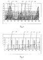
- a mixer signal consisting of single pulses 18 with a frequency slightly shifted to the pulse period 1 / F i .
- At the output of the mixer results in an amplitude modulated output signal 14 with an underlying high-frequency carrier frequency.
- the envelope of this output signal 14 has two signal pulses, one associated with the time-transformed start pulse 15 and the other with the time-transformed stop pulse 16.
- the signals in the low frequency range can be further processed and digitized.
- the influence of the systematic runtime error of the electronic components is reduced by the time expansion factor of the mixer stage, which promotes the accuracy of the device considerably.
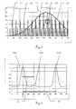
- FIG. 4 shows a section of the signals of Figure 3 in a time-expanded representation.
- the stop pulse in the RF receive signal 17 is not and the start pulse only partially reinforced. Therefore, only the start pulse is sent to the output of the mixer, the stop pulse is lost in this phase.
- the output of the mixer produces an output signal 14 with a comparatively high frequency but with additional amplitude modulation. Shown is also the envelope 19 of the output signal 14.
- FIG. 5 likewise shows the representation of an enlarged section of FIG. 3, moreover the envelope 19 or the low-pass filtered and time-extended start pulse 15 is shown.
- the detection of the start pulse in the received signal 17 by the mixer signal 18 and thus the forwarding to the output can be seen.
- the time-shifted, smaller stop pulse in the received signal 17, however, is not detected by the mixer signal 18 in this phase and therefore does not appear at the output of the mixer.
- Forwarded is a high-frequency, amplitude-modulated output signal 14 from which the envelope 19 describes the time-transformed start or stop signal.
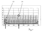
- the period of a signal pulse sequence comprises a first start pulse 15a and a stop pulse 16a, wherein a second start pulse 15a 'following with a time-extended pulse interval interval 22 as L i can also be seen in this illustration.
- the measurand to be determined here is the time, ie the delay 21, between the first start pulse 16a and the stop pulse 15b.
- Fig. 7 illustrates the effect of heterodyne subsampling. If the device comprises only one high-frequency mixer, part of the signal energy is lost. This lossy effect can be seen at the points 24 where the control pulse of the mixer falls between the start and stop pulses. To avoid this, several mixer blocks are used parallel to each other in the receiving channel. The phases of the control signals are shifted by the fraction of the number of parallel mixer against each other. This ensures that at least one of the mixers per pulse period Ti performs an effective signal sampling 23 and thereby no signal energy is lost. The sensitivity of such a receiving device reaches that of a pulsed transit time meter and therefore differs considerably from that of a conventional phase meter.
Landscapes
- Physics & Mathematics (AREA)
- Engineering & Computer Science (AREA)
- Electromagnetism (AREA)
- Computer Networks & Wireless Communication (AREA)
- General Physics & Mathematics (AREA)
- Radar, Positioning & Navigation (AREA)
- Remote Sensing (AREA)
- Optical Radar Systems And Details Thereof (AREA)
- Measurement Of Optical Distance (AREA)
Priority Applications (7)
| Application Number | Priority Date | Filing Date | Title |
|---|---|---|---|
| EP04030085A EP1672382A1 (de) | 2004-12-18 | 2004-12-18 | Einkanal-Heterodyn -Distanzmessverfahren |
| PCT/EP2005/013242 WO2006063740A1 (de) | 2004-12-18 | 2005-12-09 | Einkanal-heterodyn-distanzmessverfahren |
| AT05817590T ATE512374T1 (de) | 2004-12-18 | 2005-12-09 | Einkanal-heterodyn-distanzmessverfahren |
| US11/721,977 US7623222B2 (en) | 2004-12-18 | 2005-12-09 | Single-channel heterodyne distance-measuring method |
| EP05817590A EP1825294B1 (de) | 2004-12-18 | 2005-12-09 | Einkanal-heterodyn-distanzmessverfahren |
| JP2007545908A JP5108526B2 (ja) | 2004-12-18 | 2005-12-09 | 単一チャンネルヘテロダイン距離測定方法 |
| CN2005800434851A CN101080647B (zh) | 2004-12-18 | 2005-12-09 | 单通道外差距离测量方法 |
Applications Claiming Priority (1)
| Application Number | Priority Date | Filing Date | Title |
|---|---|---|---|
| EP04030085A EP1672382A1 (de) | 2004-12-18 | 2004-12-18 | Einkanal-Heterodyn -Distanzmessverfahren |
Publications (1)
| Publication Number | Publication Date |
|---|---|
| EP1672382A1 true EP1672382A1 (de) | 2006-06-21 |
Family
ID=34927846
Family Applications (2)
| Application Number | Title | Priority Date | Filing Date |
|---|---|---|---|
| EP04030085A Withdrawn EP1672382A1 (de) | 2004-12-18 | 2004-12-18 | Einkanal-Heterodyn -Distanzmessverfahren |
| EP05817590A Active EP1825294B1 (de) | 2004-12-18 | 2005-12-09 | Einkanal-heterodyn-distanzmessverfahren |
Family Applications After (1)
| Application Number | Title | Priority Date | Filing Date |
|---|---|---|---|
| EP05817590A Active EP1825294B1 (de) | 2004-12-18 | 2005-12-09 | Einkanal-heterodyn-distanzmessverfahren |
Country Status (6)
| Country | Link |
|---|---|
| US (1) | US7623222B2 (ja) |
| EP (2) | EP1672382A1 (ja) |
| JP (1) | JP5108526B2 (ja) |
| CN (1) | CN101080647B (ja) |
| AT (1) | ATE512374T1 (ja) |
| WO (1) | WO2006063740A1 (ja) |
Cited By (2)
| Publication number | Priority date | Publication date | Assignee | Title |
|---|---|---|---|---|
| CN104364671A (zh) * | 2012-06-27 | 2015-02-18 | 莱卡地球系统公开股份有限公司 | 距离测量方法和距离测量元件 |
| EP3405808A4 (en) * | 2016-01-22 | 2019-09-25 | Mezmeriz, Inc. | SIGNAL DETECTION APPARATUS, METHOD AND APPLICATIONS |
Families Citing this family (44)
| Publication number | Priority date | Publication date | Assignee | Title |
|---|---|---|---|---|
| US7714990B2 (en) * | 2004-12-16 | 2010-05-11 | Hilti Aktiengesellschaft | Hand-held laser distance measuring device with a pulse reflection mixing method |
| EP1672383A1 (de) * | 2004-12-18 | 2006-06-21 | Leica Geosystems AG | Elektronisches Messverfahren |
| USRE46672E1 (en) | 2006-07-13 | 2018-01-16 | Velodyne Lidar, Inc. | High definition LiDAR system |
| NL2002116C (nl) * | 2008-10-20 | 2010-04-21 | Stichting Noble House | Werkwijze voor het bepalen van de aanwezigheid van een zender en een ontvanger en een systeem ingericht daarvoor. |
| DE102009012646A1 (de) * | 2009-03-11 | 2010-09-23 | Amt Gmbh | Abstandsmessung |
| US8497478B2 (en) * | 2009-03-31 | 2013-07-30 | Osram Sylvania Inc. | High voltage supply to increase rise time of current through light source in an optical sensor system |
| FI122454B (fi) * | 2009-08-27 | 2012-01-31 | Outotec Oyj | Menetelmä ja laitteisto kuljetinhihnalla kuljetettavan materiaalipatjan pinnankorkeuden mittaamiseksi |
| AU2010334833B2 (en) * | 2009-12-22 | 2013-10-17 | Leica Geosystems Ag | Highly accurate distance measurement device |
| US9100113B2 (en) * | 2011-04-26 | 2015-08-04 | Forschungsverbund Berlin E.V. | Auto-heterodyne receiver |
| CN102221356B (zh) * | 2011-05-31 | 2014-03-12 | 哈尔滨工业大学 | 多普勒振镜正弦调制多光束激光外差二次谐波测量激光入射角度的装置及方法 |
| CN102221355B (zh) * | 2011-05-31 | 2012-09-05 | 哈尔滨工业大学 | 多普勒振镜正弦调制多光束激光外差测量激光入射角度的装置及方法 |
| US8988660B2 (en) * | 2011-06-29 | 2015-03-24 | Silicon Laboratories Inc. | Optical detector |
| JP5753449B2 (ja) * | 2011-06-30 | 2015-07-22 | 株式会社トプコン | 光波距離測定方法及び光波距離装置 |
| EP2589980A1 (de) | 2011-11-04 | 2013-05-08 | Leica Geosystems AG | Entfernungsmesser |
| EP2597483B8 (de) | 2011-11-25 | 2017-06-07 | Safran Vectronix AG | Entfernungsmesser |
| EP2600168A1 (de) | 2011-12-01 | 2013-06-05 | Leica Geosystems AG | Entfernungsmesser |
| EP3171201B1 (de) | 2012-03-07 | 2018-05-09 | Safran Vectronix AG | Entfernungsmesser |
| EP2680029A1 (de) * | 2012-06-27 | 2014-01-01 | Leica Geosystems AG | Distanzmessverfahren und Distanzmesser |
| US20140149023A1 (en) * | 2012-11-29 | 2014-05-29 | Ford Global Technologies, Llc | Method and system for engine position control |
| US9664786B2 (en) | 2013-08-21 | 2017-05-30 | Selex Es Inc. | Method and apparatus for distance measuring equipment (DME/normal) using alternative pulse shapes |
| EP2843440B1 (de) | 2013-08-28 | 2018-11-28 | Safran Vectronix AG | Stabilisierte Entfernungsmessung im Beobachtungsgerät |
| EP3088914B1 (en) | 2013-12-27 | 2020-05-06 | Ricoh Company, Ltd. | Distance measuring apparatus, electronic apparatus, distance measuring method, and distance measuring program |
| CN105890575B (zh) * | 2014-12-10 | 2019-02-12 | 青岛理工大学 | 普通及特殊环境的人工智能机器视觉识别方法及装置 |
| FR3034513A1 (ja) * | 2015-04-02 | 2016-10-07 | Stmicroelectronics (Grenoble 2) Sas | |
| GB201514249D0 (en) * | 2015-08-12 | 2015-09-23 | Trw Ltd | Processing received radiation reflected from a target |
| US10627490B2 (en) | 2016-01-31 | 2020-04-21 | Velodyne Lidar, Inc. | Multiple pulse, LIDAR based 3-D imaging |
| WO2017164989A1 (en) | 2016-03-19 | 2017-09-28 | Velodyne Lidar, Inc. | Integrated illumination and detection for lidar based 3-d imaging |
| US10393877B2 (en) | 2016-06-01 | 2019-08-27 | Velodyne Lidar, Inc. | Multiple pixel scanning LIDAR |
| US10386465B2 (en) | 2017-03-31 | 2019-08-20 | Velodyne Lidar, Inc. | Integrated LIDAR illumination power control |
| CN110520753B (zh) | 2017-04-13 | 2023-05-30 | 三菱电机株式会社 | 激光雷达装置 |
| WO2018208843A1 (en) * | 2017-05-08 | 2018-11-15 | Velodyne Lidar, Inc. | Lidar data acquisition and control |
| JP6991034B2 (ja) * | 2017-10-19 | 2022-01-12 | 株式会社トプコン | 光波距離計及びフィードバック信号の変調周波数決定方法 |
| US11294041B2 (en) | 2017-12-08 | 2022-04-05 | Velodyne Lidar Usa, Inc. | Systems and methods for improving detection of a return signal in a light ranging and detection system |
| EP3599485B1 (de) * | 2018-07-23 | 2024-03-27 | MicroVision, Inc. | Verfahren und vorrichtung zur optischen distanzmessung |
| US11971507B2 (en) | 2018-08-24 | 2024-04-30 | Velodyne Lidar Usa, Inc. | Systems and methods for mitigating optical crosstalk in a light ranging and detection system |
| US10712434B2 (en) | 2018-09-18 | 2020-07-14 | Velodyne Lidar, Inc. | Multi-channel LIDAR illumination driver |
| US11082010B2 (en) | 2018-11-06 | 2021-08-03 | Velodyne Lidar Usa, Inc. | Systems and methods for TIA base current detection and compensation |
| US11885958B2 (en) | 2019-01-07 | 2024-01-30 | Velodyne Lidar Usa, Inc. | Systems and methods for a dual axis resonant scanning mirror |
| CN110221308B (zh) * | 2019-03-04 | 2021-04-30 | 中国电子科技集团公司第十一研究所 | 一种相干脉冲激光测距的方法、相关装置及存储介质 |
| US10613203B1 (en) | 2019-07-01 | 2020-04-07 | Velodyne Lidar, Inc. | Interference mitigation for light detection and ranging |
| JP2021156688A (ja) * | 2020-03-26 | 2021-10-07 | ソニーセミコンダクタソリューションズ株式会社 | 測距システム |
| FR3119683B1 (fr) | 2021-02-10 | 2024-03-08 | Bertin Technologies Sa | Système et procédé d’observation et procédé de fabrication d’un tel système |
| CN115236685B (zh) * | 2022-09-21 | 2022-12-23 | 成都量芯集成科技有限公司 | 一种相位法激光测距装置 |
| CN116381597B (zh) * | 2023-05-29 | 2023-08-25 | 成都唯博星辰科技有限公司 | 一种宽带单通道测向系统及实现方法 |
Citations (4)
| Publication number | Priority date | Publication date | Assignee | Title |
|---|---|---|---|---|
| US5428439A (en) * | 1992-09-23 | 1995-06-27 | The Texas A&M University System | Range measurement system |
| US5889490A (en) * | 1996-08-05 | 1999-03-30 | Wachter; Eric A. | Method and apparatus for improved ranging |
| DE10112833C1 (de) * | 2001-03-16 | 2003-03-13 | Hilti Ag | Verfahren und Einrichtung zur elektrooptischen Distanzmessung |
| EP1450128A1 (de) * | 2003-02-19 | 2004-08-25 | Leica Geosystems AG | Verfahren und Vorrichtung zur Ableitung geodätischer Entfernungsinformationen |
Family Cites Families (3)
| Publication number | Priority date | Publication date | Assignee | Title |
|---|---|---|---|---|
| JPS60244881A (ja) * | 1984-05-21 | 1985-12-04 | Tech Res & Dev Inst Of Japan Def Agency | 距離追尾レ−ダ |
| JPS6443784A (en) * | 1987-08-12 | 1989-02-16 | Japan Tech Res & Dev Inst | Distance decision device for pulse radar |
| US5347525A (en) * | 1993-02-19 | 1994-09-13 | Sri International | Generation of multiple stabilized frequency references using a mode-coupled laser |
-
2004
- 2004-12-18 EP EP04030085A patent/EP1672382A1/de not_active Withdrawn
-
2005
- 2005-12-09 CN CN2005800434851A patent/CN101080647B/zh active Active
- 2005-12-09 US US11/721,977 patent/US7623222B2/en active Active
- 2005-12-09 EP EP05817590A patent/EP1825294B1/de active Active
- 2005-12-09 AT AT05817590T patent/ATE512374T1/de active
- 2005-12-09 JP JP2007545908A patent/JP5108526B2/ja active Active
- 2005-12-09 WO PCT/EP2005/013242 patent/WO2006063740A1/de active Application Filing
Patent Citations (4)
| Publication number | Priority date | Publication date | Assignee | Title |
|---|---|---|---|---|
| US5428439A (en) * | 1992-09-23 | 1995-06-27 | The Texas A&M University System | Range measurement system |
| US5889490A (en) * | 1996-08-05 | 1999-03-30 | Wachter; Eric A. | Method and apparatus for improved ranging |
| DE10112833C1 (de) * | 2001-03-16 | 2003-03-13 | Hilti Ag | Verfahren und Einrichtung zur elektrooptischen Distanzmessung |
| EP1450128A1 (de) * | 2003-02-19 | 2004-08-25 | Leica Geosystems AG | Verfahren und Vorrichtung zur Ableitung geodätischer Entfernungsinformationen |
Cited By (5)
| Publication number | Priority date | Publication date | Assignee | Title |
|---|---|---|---|---|
| CN104364671A (zh) * | 2012-06-27 | 2015-02-18 | 莱卡地球系统公开股份有限公司 | 距离测量方法和距离测量元件 |
| CN104364671B (zh) * | 2012-06-27 | 2017-08-25 | 莱卡地球系统公开股份有限公司 | 距离测量方法和距离测量元件 |
| US10120077B2 (en) | 2012-06-27 | 2018-11-06 | Leica Geosystems Ag | Distance measuring method and distance measuring element |
| EP3405808A4 (en) * | 2016-01-22 | 2019-09-25 | Mezmeriz, Inc. | SIGNAL DETECTION APPARATUS, METHOD AND APPLICATIONS |
| US10859614B2 (en) | 2016-01-22 | 2020-12-08 | Mezmeriz Inc. | Signal detection apparatus, method, and applications |
Also Published As
| Publication number | Publication date |
|---|---|
| CN101080647A (zh) | 2007-11-28 |
| JP5108526B2 (ja) | 2012-12-26 |
| EP1825294B1 (de) | 2011-06-08 |
| EP1825294A1 (de) | 2007-08-29 |
| WO2006063740A1 (de) | 2006-06-22 |
| ATE512374T1 (de) | 2011-06-15 |
| US20080304043A1 (en) | 2008-12-11 |
| CN101080647B (zh) | 2012-04-11 |
| JP2008524563A (ja) | 2008-07-10 |
| US7623222B2 (en) | 2009-11-24 |
Similar Documents
| Publication | Publication Date | Title |
|---|---|---|
| EP1825294B1 (de) | Einkanal-heterodyn-distanzmessverfahren | |
| EP1825293B1 (de) | Elektronisches messverfahren | |
| EP1595110B1 (de) | Verfahren und vorrichtung zur ableitung geodätischer entfernungsinformationen | |
| EP1797457B1 (de) | Elektrooptisches distanzmessverfahren mit bestimmung eines nichtidealen chirpverlaufs | |
| EP2406659B1 (de) | Abstandsmessung | |
| DE102012223689B3 (de) | Messvorrichtung und Verfahren zur Referenzierung für einen digitalen Laserentfernungsmesser, sowie Laserentfernungsmesser | |
| DE102009024460A1 (de) | Auswerteeinrichtung, Messanordnung und Verfahren zur Weglängenmessung | |
| DE10022054B4 (de) | Optischer Distanzsensor | |
| WO2006089845A1 (de) | Phasenrauschkompensation für interferometrische absolutdistanzmesser | |
| WO2007009833A1 (de) | Verfahren und schaltungsanordnung zur genauen entfernungsbestimmung | |
| EP3143425A1 (de) | Mehrzielfähiger laserentfernungsmesser | |
| WO2018202696A1 (de) | Verfahren und vorrichtung zur messung einer schichtdicke eines objekts | |
| EP3657203A1 (de) | Elektrooptischer entfernungsmesser und entfernungsmessverfahren | |
| EP2440949B1 (de) | Verfahren und vorrichtung zur messung einer entfernungsänderung | |
| EP1877825A1 (de) | Verfahren und vorrichtung zur bestimmung eines abstands zu einem zielobjekt | |
| DE102013207647A1 (de) | Lichtlaufzeitkamerasystem | |
| DE102013207654A1 (de) | Lichtlaufzeitkamerasystem | |
| DE10350489B4 (de) | Optischer Sensor | |
| DE102021105770A1 (de) | Abstandsmessung mittels eines aktiven optischen Sensorsystems | |
| DE102008045366B4 (de) | Vorrichtung und Verfahren zur Geschwindigkeitsmessung | |
| DE102013207650A1 (de) | Lichtlaufzeitkamerasystem | |
| DE10348104B3 (de) | Optischer Sensor | |
| DE102019112300A1 (de) | Bestimmung der Entfernung eines Objekts | |
| DE10331376B3 (de) | Optischer Sensor | |
| DE102010053993A1 (de) | Vorrichtung zur Entfernungsmessung nach dem Prinzip der Phasenmessung mit zusätzlicher Trägermodulation |
Legal Events
| Date | Code | Title | Description |
|---|---|---|---|
| PUAI | Public reference made under article 153(3) epc to a published international application that has entered the european phase |
Free format text: ORIGINAL CODE: 0009012 |
|
| AK | Designated contracting states |
Kind code of ref document: A1 Designated state(s): AT BE BG CH CY CZ DE DK EE ES FI FR GB GR HU IE IS IT LI LT LU MC NL PL PT RO SE SI SK TR |
|
| AX | Request for extension of the european patent |
Extension state: AL BA HR LV MK YU |
|
| AKX | Designation fees paid | ||
| REG | Reference to a national code |
Ref country code: DE Ref legal event code: 8566 |
|
| STAA | Information on the status of an ep patent application or granted ep patent |
Free format text: STATUS: THE APPLICATION IS DEEMED TO BE WITHDRAWN |
|
| 18D | Application deemed to be withdrawn |
Effective date: 20061222 |