EP1669984B1 - Trägerelement ('shipping comb') zum Schutz der Aktuator/Kopfvorrichtung einer Festplatte gegen Beschädigung während des Transports - Google Patents
Trägerelement ('shipping comb') zum Schutz der Aktuator/Kopfvorrichtung einer Festplatte gegen Beschädigung während des Transports Download PDFInfo
- Publication number
- EP1669984B1 EP1669984B1 EP20050254741 EP05254741A EP1669984B1 EP 1669984 B1 EP1669984 B1 EP 1669984B1 EP 20050254741 EP20050254741 EP 20050254741 EP 05254741 A EP05254741 A EP 05254741A EP 1669984 B1 EP1669984 B1 EP 1669984B1
- Authority
- EP
- European Patent Office
- Prior art keywords
- finger
- shipping comb
- sliders
- actuator
- end portion
- Prior art date
- Legal status (The legal status is an assumption and is not a legal conclusion. Google has not performed a legal analysis and makes no representation as to the accuracy of the status listed.)
- Expired - Lifetime
Links
Images




Classifications
-
- G—PHYSICS
- G11—INFORMATION STORAGE
- G11B—INFORMATION STORAGE BASED ON RELATIVE MOVEMENT BETWEEN RECORD CARRIER AND TRANSDUCER
- G11B21/00—Head arrangements not specific to the method of recording or reproducing
- G11B21/16—Supporting the heads; Supporting the sockets for plug-in heads
- G11B21/20—Supporting the heads; Supporting the sockets for plug-in heads while the head is in operative position but stationary or permitting minor movements to follow irregularities in surface of record carrier
- G11B21/21—Supporting the heads; Supporting the sockets for plug-in heads while the head is in operative position but stationary or permitting minor movements to follow irregularities in surface of record carrier with provision for maintaining desired spacing of head from record carrier, e.g. fluid-dynamic spacing, slider
-
- G—PHYSICS
- G11—INFORMATION STORAGE
- G11B—INFORMATION STORAGE BASED ON RELATIVE MOVEMENT BETWEEN RECORD CARRIER AND TRANSDUCER
- G11B5/00—Recording by magnetisation or demagnetisation of a record carrier; Reproducing by magnetic means; Record carriers therefor
- G11B5/48—Disposition or mounting of heads or head supports relative to record carriers ; arrangements of heads, e.g. for scanning the record carrier to increase the relative speed
- G11B5/4806—Disposition or mounting of heads or head supports relative to record carriers ; arrangements of heads, e.g. for scanning the record carrier to increase the relative speed specially adapted for disk drive assemblies, e.g. assembly prior to operation, hard or flexible disk drives
-
- G—PHYSICS
- G11—INFORMATION STORAGE
- G11B—INFORMATION STORAGE BASED ON RELATIVE MOVEMENT BETWEEN RECORD CARRIER AND TRANSDUCER
- G11B21/00—Head arrangements not specific to the method of recording or reproducing
- G11B21/16—Supporting the heads; Supporting the sockets for plug-in heads
- G11B21/22—Supporting the heads; Supporting the sockets for plug-in heads while the head is out of operative position
-
- G—PHYSICS
- G11—INFORMATION STORAGE
- G11B—INFORMATION STORAGE BASED ON RELATIVE MOVEMENT BETWEEN RECORD CARRIER AND TRANSDUCER
- G11B33/00—Constructional parts, details or accessories not provided for in the other groups of this subclass
- G11B33/02—Cabinets; Cases; Stands; Disposition of apparatus therein or thereon
- G11B33/08—Insulation or absorption of undesired vibrations or sounds
-
- G—PHYSICS
- G11—INFORMATION STORAGE
- G11B—INFORMATION STORAGE BASED ON RELATIVE MOVEMENT BETWEEN RECORD CARRIER AND TRANSDUCER
- G11B5/00—Recording by magnetisation or demagnetisation of a record carrier; Reproducing by magnetic means; Record carriers therefor
- G11B5/48—Disposition or mounting of heads or head supports relative to record carriers ; arrangements of heads, e.g. for scanning the record carrier to increase the relative speed
- G11B5/4806—Disposition or mounting of heads or head supports relative to record carriers ; arrangements of heads, e.g. for scanning the record carrier to increase the relative speed specially adapted for disk drive assemblies, e.g. assembly prior to operation, hard or flexible disk drives
- G11B5/4813—Mounting or aligning of arm assemblies, e.g. actuator arm supported by bearings, multiple arm assemblies, arm stacks or multiple heads on single arm
-
- G—PHYSICS
- G11—INFORMATION STORAGE
- G11B—INFORMATION STORAGE BASED ON RELATIVE MOVEMENT BETWEEN RECORD CARRIER AND TRANSDUCER
- G11B5/00—Recording by magnetisation or demagnetisation of a record carrier; Reproducing by magnetic means; Record carriers therefor
- G11B5/40—Protective measures on heads, e.g. against excessive temperature
-
- Y—GENERAL TAGGING OF NEW TECHNOLOGICAL DEVELOPMENTS; GENERAL TAGGING OF CROSS-SECTIONAL TECHNOLOGIES SPANNING OVER SEVERAL SECTIONS OF THE IPC; TECHNICAL SUBJECTS COVERED BY FORMER USPC CROSS-REFERENCE ART COLLECTIONS [XRACs] AND DIGESTS
- Y10—TECHNICAL SUBJECTS COVERED BY FORMER USPC
- Y10T—TECHNICAL SUBJECTS COVERED BY FORMER US CLASSIFICATION
- Y10T29/00—Metal working
- Y10T29/49—Method of mechanical manufacture
- Y10T29/49002—Electrical device making
- Y10T29/4902—Electromagnet, transformer or inductor
- Y10T29/49021—Magnetic recording reproducing transducer [e.g., tape head, core, etc.]
- Y10T29/49025—Making disc drive
-
- Y—GENERAL TAGGING OF NEW TECHNOLOGICAL DEVELOPMENTS; GENERAL TAGGING OF CROSS-SECTIONAL TECHNOLOGIES SPANNING OVER SEVERAL SECTIONS OF THE IPC; TECHNICAL SUBJECTS COVERED BY FORMER USPC CROSS-REFERENCE ART COLLECTIONS [XRACs] AND DIGESTS
- Y10—TECHNICAL SUBJECTS COVERED BY FORMER USPC
- Y10T—TECHNICAL SUBJECTS COVERED BY FORMER US CLASSIFICATION
- Y10T29/00—Metal working
- Y10T29/53—Means to assemble or disassemble
- Y10T29/5313—Means to assemble electrical device
- Y10T29/53165—Magnetic memory device
Definitions
- the present invention relates to a shipping comb for moving an actuator of a hard disk drive, and more particularly, to a shipping comb for moving an actuator of a hard disk drive having a structure which can prevent collision between sliders, each mounting a read/write head, during the movement of an actuator.
- a hard disk drive that is one of information storing devices for computers reproduces data stored from a disk or records data on the disk using a read/write head.
- the read/write head is mounted on a slider installed on an actuator. The actuator moves the head to a desired position on the rotating disk.
- FIG. 1 is a plan view illustrating a structure of a conventional hard disk drive.
- the conventional hard disk drive includes a spindle motor 12 installed on a base member 10, at least one disk 20 fixed to the spindle motor 12, and an actuator 30 moving a read/write head (not shown) for reproducing and recording data to a predetermined position on the disk 20.
- the actuator 30 includes a swing arm 32 installed on the base member 10 capable of pivoting around an actuator pivot 31, a suspension assembly 40 installed at an end portion of the swing arm 32 and supporting the slider 44 mounting the read/write head to be elastically biased toward a surface of the disk 20, and a voice coil motor (VCM) 36 rotating the swing arm 32.
- the VCM 36 includes a VCM coil 37 coupled to the other end portion of the swing arm 32 and a magnet 38 arranged to face the VCM coil 37.
- the VCM 36 configured as above is controlled by a servo control system to rotate the swing arm 32 in a direction following the Fleming's Left Hand Rule by an interaction between current applied to the VCM coil 37 and a magnetic field formed by the magnet 38. That is, when the power of the hard disk drive is on and the disk 20 starts to rotate in a direction D, the VCM 36 rotates the wing arm 32 counterclockwise in a direction A to move the slider 44 mounting the read/write head toward a recording surface of the disk 20. The slider 44 is lifted by a lift force generated by the rotating disk 20 to a predetermined height from the surface of the disk 20. In this state, the read/write head mounted on the slider 44 reproduces data or records data with respect to the recording surface of the disk 20.
- the read/write head is parked at a position outside the recording surface of the disk 20 to prevent the read/write head from colliding against the recording surface of the disk 20.
- a ramp 50 is installed outside the disk 20 and an end-tab 45 supported by the ramp 50 is provided on the suspension assembly 40.
- FIG. 2 is a perspective view illustrating the actuator shown in FIG. 1 and the conventional shipping comb installed thereon.
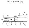
- FIG. 3 is a side view illustrating a state in which the conventional shipping comb shown in FIG. 2 is installed on the actuator.
- the actuator 30 is generally referred to as a head-stack assembly (HSA) and has a plurality of heads corresponding to the number of the recording surfaces of the disk 20.
- HSA head-stack assembly
- Each of the heads is mounted on the slider 44 which is supported by the suspension assembly 40.
- the same number of the suspension assembly 40 as that of the heads are provided at the actuator 30.
- Each of the suspension assembly 40 includes a load beam 41 coupled to an end portion of the swing arm 32 and a flexure 43 attached to the load beam 41.
- the end-tab 45 is extended from a front end portion of the load beam 41.
- the slider 44 is attached to the flexure 43.
- the rear end portion of the flexure 43 is attached to a surface of the load beam 41 that faces the disk 20 while the front end portion thereof is formed to freely move up and down.
- a dimple 42 is formed at the load beam 41.
- the dimple 42 provides a predetermined elastic force to the flexure 43.
- the actuator 30 configured as above is installed on the base member 10 of the hard disk drive after it is separately manufactured. While the actuator 30 is being transferred for this purpose, impact or vibration may be applied to the actuator 30. In this case, the sliders 44 arranged to face each other may collide with each other and be damaged accordingly. To prevent this problem, a shipping comb 60 is installed in the actuator 30.
- the shipping comb 60 includes a frame 61, an installation rod 62a and a handle 62b provided at an end portion of the frame 61, and a finger 63 provided at the other end portion of the frame 61.
- the installation rod 62a of the shipping comb 60 is inserted in an installation hole 34 formed in the swing arm 32 of the actuator 30 while the finger 63 is inserted between the load beams 41 facing each other to maintain a constant gap therebetween.
- the handle 62b is used to pivot the shipping comb 60.
- the conventional shipping comb 60 when the conventional shipping comb 60 is installed at the actuator 30, the sliders 44 facing each other may still collide with each other and be damaged thereby. That is, the conventional shipping comb 60 does not have a structure to directly prevent the collision between the sliders 44. Accordingly, during the transfer of the actuator 30, when a relatively large impact or vibration is applied to the actuator 30, the sliders 44 greatly vibrate and thus the sliders 44 facing each other may collide with each other. In this case, an air bearing surface of each of the sliders 44 may be damaged or the head mounted thereon may be damaged so that a lifting ability of the slider 44 or a read/write ability of the head may be deteriorated.
- US 5984104 and US 6687093 each disclose a shipping comb for an actuator of a hard disk drive, which actuator comprises read write heads mounted at the ends of parallel swing arms.
- the shipping combs comprise frames having fingers for insertion between the heads between the swing arms at another longitudinal location.
- a shipping comb for an actuator of a hard disk drive including a swing arm installed on a base member of the hard disk drive capable of pivoting, at least a pair of load beams coupled to an end portion of the swing arm, and at least a pair of sliders respectively coupled to the load beams to face each other
- the shipping comb comprising: a frame coupled to the actuator capable of pivoting; a first finger provided at the frame and maintaining an interval between the load beams by being inserted between the load beams; and a second finger provided at the frame and preventing collision between the sliders by being inserted between the sliders, wherein the shipping comb is characterized in that the second finger is hinge-coupled to the frame and capable of pivoting with respect to the frame.
- the length of the first finger may be greater than that of the second finger.
- the first finger may horizontally protrude from the frame and the second finger may be capable of horizontally pivoting.
- Two hinge coupling protrusions may protrude from the frame with a predetermined interval, a rear end portion of the second finger may be inserted between the two hinge coupling protrusions, and a pin insertion hole, into which a hinge pin is inserted, is coaxially formed in each of the hinge coupling protrusions and the rear end portion of the second finger.
- the first finger may be inserted between the load beams as the frame is coupled to the actuator and rotated in a direction, and then the second finger may be inserted between the sliders as the second finger is rotated in the direction.
- An installation hole may be formed in the swing arm of the actuator and an installation rod to be inserted in the installation hole may be provided at an end portion of the frame.
- a tip end portion of the first finger may be inclined to allow the first finger to be easily inserted between the load beams.
- the first finger may contact and support each of the load beams in a state in which the first finger is inserted between the load beams.
- the second finger may have a thickness smaller than an interval between the sliders so as not to contact the sliders when the second finger is inserted between the sliders.
- a tip end portion of the second finger facing the sliders may have a shape corresponding to the shape of each of the sliders.
- the shipping comb may be formed of a conductive plastic material.
- the conductive plastic material may include carbon fabric.
- the first finger and the second finger may be formed of different materials.
- the second finger may be formed of a material softer than the first finger.
- a buffer member may be attached to at least each of upper and lower surfaces of a tip end portion of the second finger.
- the buffer member may be formed of a viscoelastic material.
- the present invention thus provides a shipping comb for moving an actuator of a hard disk drive having a structure for preventing with improved reliability collision between sliders due to impact or vibration.
- FIG. 4 is a perspective view illustrating a shipping comb for moving an actuator of a hard disk drive and the actuator.
- FIG. 5 is a side view illustrating a state in which the shipping comb of FIG. 4 is installed at the actuator.
- a shipping comb 160 is installed at an actuator 130 of the hard disk drive to prevent collision between the sliders 144 which may occur during the transfer of the actuator 130.
- the actuator 130 for moving a read/write head for reproducing and recording data to a predetermined position on a disk includes a swing arm 132 installed capable of pivoting a base member of a hard disk drive and at least a pair of suspension assemblies 140, each being coupled to an end of the swing arm 132 and supporting the slider 144 mounting the head elastically biased toward a surface of the disk.
- An actuator pivot 131 is coupled to a center portion of the swing arm 132.
- a VCM coil 137 of a voice coil motor which supplies a driving power to rotate the swing arm 132 clockwise or counterclockwise is coupled to the other end portion of the swing arm 132.
- the number of the suspension assemblies 140 coupled to an end portion of the swing arm 132 is determined by the number of disks. For example, when a single disk is installed in the hard disk drive, as shown in FIGS. 4 and 5 , two sliders 144 corresponding to upper and lower surfaces of the disk are needed. A pair of the suspension assemblies 140 to support the two sliders 144 are provided. When two or more disks are installed in the hard disk drive, four or more sliders 144 corresponding to upper and lower surfaces of each disk are needed. Accordingly, two or more pairs of the suspension assemblies 140 are provided to support four or more of the sliders 144.
- the shipping comb 160 is described below based on the actuator 130 having a pair of the suspension assemblies 140 in the hard disk drive having a single disk for the convenience of explanation.
- the suspension assemblies 140 have a pair of load beams 141 coupled to the end portion of the swing arm 132 and a pair of the sliders 144, each being coupled to the load beams 141 to face each other.
- a flexure 143 is attached to a surface of each of the load beams 141 facing the disk.
- Each of the sliders 144 is attached to the flexure 143 and supported thereon.
- a rear end portion of the flexure 143 is fixedly attached to the surface of each of the load beams 141 facing the disk while a front end portion thereof is formed to freely move up and down.
- a dimple 142 is formed at each of the load beams 141. The dimple 142 provides a predetermined elastic force to the flexure 143.
- the front end portion of the flexure 143 can freely move and accordingly pitching and rolling of each of the sliders 144 attached to the flexure 143 is smoothly made.
- An end-tab 145 for parking the read/write head on a ramp may be provided on each of the load beams 141.
- the shipping comb 160 is detachably installed at the actuator 130 configured as above.
- the shipping comb 160 includes a frame 161 coupled to the actuator 130 and two fingers 163 and 164 provided at the frame 161.
- the frame 161 is coupled to the swing arm 132 of the actuator 130 to be capable of pivoting.
- an installation rod 162a protrudes from an end portion of the frame 161 and an installation hole 134 is formed on the swing arm 130.
- a handle 162b may be provided at an end portion of the frame 161 to protrude in the direction opposite to the installation rod 162a.
- the first finger 163 of the two fingers 163 and 164 horizontally protrudes from an approximately middle portion of the frame 161 and is inserted between the load beams 141.
- a tip end portion of the first finger 163 is inclined to be easily inserted between the load beams 141.
- Upper and lower surfaces of the first finger 163 inserted between the load beams 141 contact the respective load beams 141.
- the first finger 141 has the substantially same thickness as a gap between the load beams 141. Since the load beams 141 contact the first finger 163 and are supported thereby, the gap between the load beams 141 can be maintained constant.
- the second finger 164 of the two fingers 163 and 164 horizontally protrudes from the other end of the frame 161 and is inserted between the sliders 144.
- the second finger 164 has a thickness smaller than a gap between the sliders 144.
- the second finger 164 does not contact the sliders 144 when inserted between the sliders 144, the second finger 164 is easily inserted between the sliders 144.
- Upper and lower surfaces of the second finger 164 inserted between the sliders 144 are separated a predetermined distance from the respective sliders 144. Accordingly, when impact or vibration is not applied to the actuator 130, the sliders 144 do not contact the second finger 164.
- the tip end portion of the second finger 164 that is, a portion facing the sliders 144, has a shape corresponding to the shape of the sliders 144.
- the tip end portion of the second finger 164 may have a rectangular shape having an area larger than that of each of the sliders 144.
- the second finger 164 As described above, as the second finger 164 is inserted between the sliders 144 facing each other, even when a relatively large impact or vibration is applied from the outside during the transfer of the actuator 130, the direct collision between the sliders 144 can be prevented by the second finger 164. Also, when the sliders 144 vibrate due to impact or vibration and thus contact the second finger 164, since a gap between each of the sliders 144 and the second finger 164 is small, a range of vibration of the sliders 144 is remarkably reduced, compared to the prior art. Thus, even if the sliders 144 contact the second finger 164, the sliders 144 and the head mounted thereon are hardly damaged.
- the shipping comb 160 may be manufactured by plastic injection molding.
- the frame 161, the installation rod 162a, the handle 162b, and the first and second fingers 163 and 164 may be integrally formed.
- the frame 161, the installation rod 162a, the handle 162b, and the first and second fingers 163 and 164 may be manufactured by using a single sort of a plastic material.
- ESD electrostatic discharge
- a conductive plastic material including carbon fiber of about 15% is used.
- the shipping comb 160 may be integrally formed by injection molding using two different plastic materials.
- the frame 161, the installation rod 162a, the handle 162b, and the first finger 163 are formed of the same first material while the second finger 164 may be formed of a second material different from the first material.
- the frame 161, the installation rod 162a, the handle 162b, and the first finger 163 are structurally coupled to the actuator 130 or contact the same, a material exhibiting a relatively higher rigidity is used therefor.
- the second finger 164 contacts the sliders 144 when impact or vibration is applied to the actuator 130, the second finger 164 is formed of a relatively soft material to absorb the impact generated due to the collision with the sliders 144.
- FIG. 6 is a perspective view illustrating a modified example of a second finger of the shipping comb shown in FIG. 4 .
- a buffer member 165 may be attached to the upper and lower surfaces of at least the tip end portion of the second finger 164.
- the buffer member 165 may be formed of a viscoelastic material having a superior buffering property such as insulation rubber or silicon rubber.
- the buffer member 165 absorbs impact generated due to contact between the second finger 164 and the slider 144, a damage to the air bearing surface of the slider 144 and the head mounted can be effectively prevented.
- FIG. 7 is a plan view for explaining a process of installing the shipping comb of FIG. 4 at the actuator.
- the installation rod 162a of the shipping comb 160 is inserted in the installation hole 134 of the swing arm 132.
- the frame 161 is rotated using the handle 162b around the installation rod 162a by a predetermined angle in a direction A.
- the first finger 163 is inserted between the load beams 141, the load beams 141 are separated a predetermined distance from each other. Accordingly, the interval between the sliders 144 facing each other increases.
- the second finger164 is inserted between the sliders 144 facing each other. Since the interval between the sliders 144 facing each other is already increased, the second finger 164 can be easily inserted between the sliders 144 without contacting the sliders 144.
- the first finger 163 and the second finger 164 are sequentially and continuously inserted between the load beams 141 and the sliders 144, respectively, by a single pivotal movement of the frame 161.
- the length of the first finger 163 is greater than that of the second finger 164.
- FIG. 8 is a perspective view illustrating a shipping comb for moving an actuator of a hard disk drive according to an embodiment of the present invention and the actuator.
- FIG. 9 is a perspective view illustrating a hinge coupling structure of the second finger of FIG. 8 .
- FIG. 10 is a side view illustrating a state in which the shipping comb of FIG. 8 is installed at the actuator.
- a shipping comb 260 includes a frame 261 coupled to the actuator 130, a first finger 263 integrally formed with the frame 261, and a second finger 264 hinge-coupled to the frame 261 capable of pivoting by a predetermined angle.
- the frame 261 is coupled to the swing arm 132 capable of pivoting as an installation rod 262a protruding from an end portion of the frame 261 is inserted in the installation hole 134 formed in the swing arm 132.
- the first finger 263 horizontally protruding from the frame 261 to be inserted between the load beams 141 so that the interval between the load beams 141 is maintained. Since the structure and operation of the frame 261 and the first finger 263 are the same as those of the above-described previous shipping comb 160, a detailed description thereof will be omitted herein.
- the second finger 264 is inserted between the sliders 144 by hinge-coupled to the frame 261 and horizontally pivoting.
- the second finger 264 and the frame 261 are hinge-coupled in a variety of manners known to those skilled in the art.
- two hinge couple protrusions 267 protruding from the frame 261 with a predetermined interval therebetween and a rear end portion of the second finger 264 is inserted between the two hinge coupling protrusions 267.
- a pin insertion hole 268 is coaxially formed at each of the hinge coupling protrusions 267 and the rear end portion of the second finger 264 so that a hinge pin 266 is inserted in the pin insertion hole 268.
- the second finger 264 has a thickness smaller than the interval between the sliders 144.
- the tip end portion of the second finger 264 may have a shape corresponding to the shape of each of the sliders 144, for example, a rectangular shape having an area larger than that of each of the sliders 144. Since the characteristics and operation of the second finger 264 are the same as those of the above-described previous shipping comb 160, a detailed description thereon will be omitted herein.
- the second finger 264 configured as above is inserted between the sliders 144 to prevent a direct collision between the sliders 144. Since the operation and effect of the second finger 264 are the same as those of the above-described pervious shipping comb 160, a detailed description thereof will be omitted herein.
- the shipping comb 260 may be manufactured by plastic injection molding. While the frame 261, the installation rod 262a, the handle 262b, and the first finger 263 are integrally manufactured, the second finger 264 is separately manufactured. Like the above-described previous embodiment, while all of the frame 261, the installation rod 262a, the handle 262b, the first finger 263, and the second finger 264 may be manufactured using a single plastic material, the second finger 264 may be manufactured using other plastic material. Using a conductive plastic material including about 15% carbon fiber as the plastic material can prevent the ESD. Manufacturing the second finger 264 using a material softer than the first finger 263 can effectively absorb an image by contact between the second finger 264 and the sliders 144.
- the buffer member 165 capable of absorbing an impact by the contact between the second finger 264 and the sliders 144, as shown in FIG. 6 may be attached to at least the upper and lower surfaces of the tip end portion of the second finger 264.
- FIG. 11 is a plan view for explaining a process of installing the shipping comb of FIG. 8 at the actuator.
- the installation rod 262a of the shipping comb 260 is inserted in the installation hole 134 of the swing arm 132.
- the frame 261 is rotated using the handle 262b by a predetermined angle around the installation rod 262a in the direction A.
- the first finger 263 is inserted between the load beams 141, the load beams 141 are separated from each other to have a predetermined interval therebetween. Accordingly, the interval between the sliders 144 facing each other increases.
- the second finger 264 is rotated around the hinge pin 266 in the direction A to be inserted between the sliders 144 facing each other. Since the interval between the sliders 144 facing each other is already increased, the second finger 264 can be easily inserted between the sliders 144 without contacting the sliders 144.
- the first finger 263 is inserted between the load beams 141 by the rotation of the frame 261 and then the second finger 264 is inserted between the sliders 144 by the rotation of the second finger 264.
- the collision between the sliders can be prevented with improved reliability when a relatively large impact or vibration is applied from the outside during the transfer of the actuator.
- the damage to the air bearing surface of the slider and the read/write head due to the collision between the sliders is prevented.
Landscapes
- Supporting Of Heads In Record-Carrier Devices (AREA)
- Moving Of Heads (AREA)
Claims (19)
- Trägerelement (Shipping Comb) für einen Aktuator (130) eines Festplattenlaufwerks, wobei der Aktuator (130) einen Schwingarm (132), der auf einem Basiselement des Festplattenlaufwerks angeordnet und drehbar ist, mindestens ein Paar Lastträger (141), die mit einem Endabschnitt des Schwingarms (132) gekoppelt sind, und mindestens ein Paar Schleifer (144) aufweist, die jeweils mit den Lastträgern (141) so gekoppelt sind, dass sie einander zugewandt sind, wobei das Trägerelement umfasst:einen drehbaren Rahmen (261) zum Koppeln mit dem Aktuator (130),einen ersten Finger (263), der integral mit dem Rahmen (261) ausgebildet ist, um ein Intervall zwischen den Lastträgern (141) einzuhalten, indem er zwischen die Lastträger (141) eingesetzt ist, undeinen zweiten Finger (264), der am Rahmen (261) vorgesehen ist, um eine Kollision zwischen den Schleifern (144) zu verhindern, indem er zwischen die Schleifer (144) eingesetzt ist,wobei das Trägerelement dadurch gekennzeichnet ist, dass der zweite Finger (264) über ein Scharnier mit dem Rahmen (261) gekoppelt ist und in Bezug auf den Rahmen (261) drehbar ist.
- Trägerelement nach Anspruch 1, wobei die Länge des ersten Fingers (263) größer ist als die des zweiten Fingers (264).
- Trägerelement nach Anspruch 1, wobei der erste Finger (263) horizontal vom Rahmen (261) absteht und der zweite Finger (264) horizontal drehbar ist.
- Trägerelement nach einem der vorhergehenden Ansprüche, wobei zwei Scharnierkopplungsansätze (267) vom Rahmen (261) mit einem vorgegebenen Intervall abstehen, ein hinterer Endabschnitt des zweiten Fingers (264) zwischen die beiden Scharnierkopplungsansätze (267) eingesetzt ist und eine Stifteinsetzöffnung (268, 269), in die ein Scharnierstift (266) eingesetzt ist, in jedem der Scharnierkopplungsansätze (267) und dem hinteren Endabschnitt des zweiten Fingers (264) koaxial ausgebildet ist.
- Trägerelement nach einem der vorhergehenden Ansprüche, wobei der erste Finger (263) zwischen die Lastträger (141) eingesetzt wird, wenn der Rahmen (261) mit dem Aktuator (130) gekoppelt ist und sich in eine Richtung dreht, und dann der zweite Finger (264) zwischen die Schleifer (144) eingesetzt wird, wenn der zweite Finger (264) sich in die Richtung dreht.
- Trägerelement nach einem der vorhergehenden Ansprüche, wobei eine Einsetzöffnung (134) im Schwingarm (132) des Aktuators (130) ausgebildet ist und ein Einsetzstab (262a) zum Einsetzen in die Einsetzöffnung (134) an einem Endabschnitt des Rahmens (261) vorgesehen ist.
- Trägerelement nach einem der vorhergehenden Ansprüche, wobei ein Spitzenendabschnitt des ersten Fingers (263) so geneigt ist, dass es möglich ist, den ersten Finger (263) leicht zwischen die Lastträger (141) einzusetzen.
- Trägerelement nach einem der vorhergehenden Ansprüche, wobei der erste Finger (263) dazu ausgebildet ist, mit jedem der Lastträger (141) in Kontakt zu kommen und diese zu stützen, wenn der erste Finger (263) zwischen die Lastträger (141) eingesetzt ist.
- Trägerelement nach einem der vorhergehenden Ansprüche, wobei der zweite Finger (264) eine geringere Dicke aufweist als ein Intervall zwischen den Schleifern (144), so dass er nicht mit den Schleifern (144) in Kontakt kommt, wenn der zweite Finger (264) zwischen die Schleifer (144) eingesetzt ist.
- Trägerelement nach einem der vorhergehenden Ansprüche, wobei ein Spitzenendabschnitt des zweiten Fingers (264), der den Schleifen (144) zugewandt ist, eine Form aufweist, die der Form eines jeweiligen Schleifers (144) entspricht.
- Trägerelement nach einem der vorhe gehenden Ansprüche, wobei ein Spitzenendabschnitt des zweiten Fingers (264) eine rechteckige Form aufweist.
- Trägerelement nach einem der vorhe gehenden Ansprüche, wobei ein Spitzenendabschnitt des zweiten Fingers (264) eine größere Fläche aufweist als eine Fläche des Schleifers (144).
- Trägerelement nach einem der vorhergehenden Ansprüche, wobei das Trägerelement aus einem leitfähigen Känststoffmaterial gebildet ist.
- Trägerelement nach Anspruch 13, wobei das leitfähige Kunststoffmaterial Kohlenstoffgewebe beinhaltet.
- Trägerelement nach einem der vorhergehenden Ansprüche, wobei der erste Finger (263) und der zweite Finger (264) aus unterschiedlichen Materialien gebildet sind.
- Trägerelement nach Anspruch 15, wobei der zweite Finger (264) aus einem weicheren Material gebildet ist als der erste Finger (163).
- Trägerelement nach einem der vorhergehenden Ansprüche, wobei ein Pufferelement mindestens an jeder oberen und unteren Seite eines Spitzenendabschnitts des zweiten Fingers (264) angebracht ist.
- Trägerelement nach Anspruch 17, wobei das Pufferelement aus viskoelastischem Material gebildet ist.
- Aktuatoranordnung für ein Festplattenlaufwerk, wobei die Aktuatoranordnung umfasst:einen Schwingarm (132) zur Installation auf einem Basiselement des Festplattenlaufwerks, der drehbar ausgebildet ist,mindestens ein Paar Lastträger (141), die mit einem Endabschnitt des Schwingarms (132) gekoppelt sind,mindestens ein Paar Schleifer (144), die jeweils mit den Lastträgern (141) so gekoppelt sind, dass sie einander zugewandt sind, unddas Trägerelement nach einem der vorhergehenden Ansprüche.
Applications Claiming Priority (1)
| Application Number | Priority Date | Filing Date | Title |
|---|---|---|---|
| KR20040102210A KR100585167B1 (ko) | 2004-12-07 | 2004-12-07 | 하드 디스크 드라이브의 액츄에이터 이송용 쉬핑 콤 |
Publications (3)
| Publication Number | Publication Date |
|---|---|
| EP1669984A2 EP1669984A2 (de) | 2006-06-14 |
| EP1669984A3 EP1669984A3 (de) | 2007-11-14 |
| EP1669984B1 true EP1669984B1 (de) | 2010-01-13 |
Family
ID=36039893
Family Applications (1)
| Application Number | Title | Priority Date | Filing Date |
|---|---|---|---|
| EP20050254741 Expired - Lifetime EP1669984B1 (de) | 2004-12-07 | 2005-07-28 | Trägerelement ('shipping comb') zum Schutz der Aktuator/Kopfvorrichtung einer Festplatte gegen Beschädigung während des Transports |
Country Status (6)
| Country | Link |
|---|---|
| US (1) | US7433158B2 (de) |
| EP (1) | EP1669984B1 (de) |
| JP (1) | JP4295268B2 (de) |
| KR (1) | KR100585167B1 (de) |
| CN (1) | CN100394479C (de) |
| DE (1) | DE602005018890D1 (de) |
Families Citing this family (23)
| Publication number | Priority date | Publication date | Assignee | Title |
|---|---|---|---|---|
| JP4137775B2 (ja) * | 2003-12-02 | 2008-08-20 | Tdk株式会社 | サスペンションの保持用パレット |
| KR100630748B1 (ko) | 2005-05-17 | 2006-10-02 | 삼성전자주식회사 | 하드 디스크 드라이브의 액츄에이터 이송용 쉬핑 콤 |
| KR100734276B1 (ko) * | 2005-10-10 | 2007-07-02 | 삼성전자주식회사 | Hsa 보호부재 및 이를 이용하여 하드디스크 드라이브에hsa를 장착하는 방법 |
| KR100660912B1 (ko) * | 2006-01-13 | 2006-12-26 | 삼성전자주식회사 | 쉬핑콤 |
| DE102006026315A1 (de) * | 2006-06-02 | 2007-12-06 | Deutsche Thomson Ohg | Schwingarm-Aktuator für eine Abtasteinrichtung |
| US8144431B2 (en) * | 2007-04-04 | 2012-03-27 | Hitachi Global Storage Technologies, Netherlands B.V. | Flex cable assembly for vibration reduction in HDD applications |
| US7653983B1 (en) | 2007-06-26 | 2010-02-02 | Western Digital Technologies, Inc. | Manufacturing assembly for manufacturing a disk drive |
| US8156633B1 (en) | 2008-03-12 | 2012-04-17 | Western Digital Technologies, Inc. | Transport comb for head stack assembly |
| US7932314B2 (en) * | 2008-07-28 | 2011-04-26 | Ovation Polymer Technology And Engineered Materials, Inc. | Electrically conductive thermoplastic polymer composition |
| US20110038074A1 (en) * | 2009-08-17 | 2011-02-17 | Sae Magnetics (Hk) Ltd. | Ramp for a hard disc drive |
| US8248733B1 (en) | 2010-06-25 | 2012-08-21 | Western Digital Technologies, Inc. | Shipping comb and ramp for disk drive assembly |
| US9230579B1 (en) | 2012-09-21 | 2016-01-05 | Western Digital Technologies, Inc. | Comb gripper for use with a shipping comb and a ramp in the assembly of a disk drive |
| US11423927B2 (en) | 2018-04-27 | 2022-08-23 | Seagate Technology Llc | Assembly that enables reduction in disk to disk spacing |
| US11043235B2 (en) | 2018-04-27 | 2021-06-22 | Seagate Technology Llc | Assembly that enables reduction in disk to disk spacing |
| US10811045B2 (en) | 2018-04-27 | 2020-10-20 | Seagate Technology Llc | Assembly that enables reduction in disk to disk spacing |
| US10706879B2 (en) | 2018-07-19 | 2020-07-07 | Western Digital Technologies, Inc. | Vertically translating load/unload ramp mechanism for cold storage data storage device |
| WO2021011011A1 (en) * | 2019-07-18 | 2021-01-21 | Western Digital Technologies, Inc. | Vertically translating load/unload ramp mechanism for cold storage data storage device |
| US11094347B1 (en) | 2020-04-30 | 2021-08-17 | Seagate Technology Llc | Split ramp for data storage devices |
| US11756579B2 (en) | 2020-06-24 | 2023-09-12 | Seagate Technology Llc | Moveable ramp for data storage device |
| US11308984B2 (en) | 2020-06-24 | 2022-04-19 | Seagate Technology Llc | Retractable ramp for data storage devices |
| US10916271B1 (en) | 2020-06-25 | 2021-02-09 | Western Digital Technologies, Inc. | Eliminating lead screw hysteresis for vertically translating load/unload ramp mechanism for data storage device |
| US11651784B2 (en) | 2020-09-02 | 2023-05-16 | Seagate Technology Llc | Actuators for an elevator drive |
| US11120834B1 (en) | 2020-09-02 | 2021-09-14 | Seagate Technology Llc | Actuators for an elevator drive |
Family Cites Families (4)
| Publication number | Priority date | Publication date | Assignee | Title |
|---|---|---|---|---|
| US5838517A (en) * | 1995-12-01 | 1998-11-17 | International Business Machines Corporation | Shock protected high stack density suspension system |
| US5984104A (en) | 1998-01-20 | 1999-11-16 | Read-Rite Corporation | Protective carrier for magnetic head assembly |
| JP2000011556A (ja) * | 1998-06-16 | 2000-01-14 | Alps Electric Co Ltd | マイクロアクチュエータ及び磁気ヘッド装置並びに磁気記録装置 |
| US6687093B1 (en) | 2001-05-31 | 2004-02-03 | Western Digital Technologies, Inc. | Head stack assembly shipping comb with temporary locating feature for internal head disk assembly build process and disk drive manufactured using the same |
-
2004
- 2004-12-07 KR KR20040102210A patent/KR100585167B1/ko not_active Expired - Fee Related
-
2005
- 2005-07-28 DE DE200560018890 patent/DE602005018890D1/de not_active Expired - Lifetime
- 2005-07-28 EP EP20050254741 patent/EP1669984B1/de not_active Expired - Lifetime
- 2005-08-10 CN CNB2005100894289A patent/CN100394479C/zh not_active Expired - Fee Related
- 2005-08-11 US US11/201,435 patent/US7433158B2/en not_active Expired - Fee Related
- 2005-11-07 JP JP2005322720A patent/JP4295268B2/ja not_active Expired - Fee Related
Also Published As
| Publication number | Publication date |
|---|---|
| CN1787081A (zh) | 2006-06-14 |
| EP1669984A3 (de) | 2007-11-14 |
| US20060117558A1 (en) | 2006-06-08 |
| DE602005018890D1 (de) | 2010-03-04 |
| CN100394479C (zh) | 2008-06-11 |
| JP4295268B2 (ja) | 2009-07-15 |
| US7433158B2 (en) | 2008-10-07 |
| EP1669984A2 (de) | 2006-06-14 |
| JP2006164494A (ja) | 2006-06-22 |
| KR100585167B1 (ko) | 2006-06-01 |
Similar Documents
| Publication | Publication Date | Title |
|---|---|---|
| US7433158B2 (en) | Shipping comb for moving actuator of hard disk drive | |
| US7602585B2 (en) | Actuator for a disk drive having a suspension assembly including a flexure of a monolithic structure and a limiter | |
| US6233121B1 (en) | Magnetic disk drive suspension pitch motion limiter | |
| US6430007B1 (en) | Air-activated spindle/disk pack locking system | |
| US7085104B1 (en) | Low profile head gimbal assembly with shock limiting and load/unload capability | |
| KR20050122497A (ko) | 정보 저장 장치의 헤드 파킹용 램프 | |
| US6714386B1 (en) | Disc drive having a suspension limiter for improved shock performance | |
| US12380920B2 (en) | Load beam limiter tabs for HAMR head slider protection | |
| US6028745A (en) | Head restraint device for disk drive | |
| EP1555654B1 (de) | Aufhängungsanordnung mit verstärkter End-Dorne und Aktuator für Plattenlaufwerk mit dieser Anordnung | |
| JP2678401B2 (ja) | 直列型の偏りヘッド取付用サスペンション | |
| US7369366B2 (en) | Suspension assembly of actuator for disk drive with portion of load beam inclined lengthwise between limiter and leading end | |
| US7832083B2 (en) | Shipping comb usable with a head stack | |
| US8120880B2 (en) | Suspension assembly and actuator having the same in hard disk drive | |
| US20070115591A1 (en) | Suspension, head gimbal assembly and disk drive unit with the same | |
| EP1672620A2 (de) | Kopfablagerampe für Festplattenlaufwerk | |
| KR100539250B1 (ko) | 플렉셔 리미터를 가진 서스펜션 조립체와 이를 채용한디스크 드라이브용 액츄에이터 | |
| US6215627B1 (en) | Suspension assembly gimbal load beam stiffener | |
| US20110013320A1 (en) | Hard disk drive having slider limiter | |
| KR100630748B1 (ko) | 하드 디스크 드라이브의 액츄에이터 이송용 쉬핑 콤 | |
| US7142396B2 (en) | System and method for damage prevention by improving the shock resistance of a hard disk actuator arm | |
| KR100532491B1 (ko) | 디스크 드라이브의 램프 로딩 방식 헤드 파킹 장치 | |
| US20050013053A1 (en) | Suspension pitch limiters tandem design |
Legal Events
| Date | Code | Title | Description |
|---|---|---|---|
| PUAI | Public reference made under article 153(3) epc to a published international application that has entered the european phase |
Free format text: ORIGINAL CODE: 0009012 |
|
| 17P | Request for examination filed |
Effective date: 20050810 |
|
| AK | Designated contracting states |
Kind code of ref document: A2 Designated state(s): AT BE BG CH CY CZ DE DK EE ES FI FR GB GR HU IE IS IT LI LT LU LV MC NL PL PT RO SE SI SK TR |
|
| AX | Request for extension of the european patent |
Extension state: AL BA HR MK YU |
|
| PUAL | Search report despatched |
Free format text: ORIGINAL CODE: 0009013 |
|
| AK | Designated contracting states |
Kind code of ref document: A3 Designated state(s): AT BE BG CH CY CZ DE DK EE ES FI FR GB GR HU IE IS IT LI LT LU LV MC NL PL PT RO SE SI SK TR |
|
| AX | Request for extension of the european patent |
Extension state: AL BA HR MK YU |
|
| AKX | Designation fees paid |
Designated state(s): DE |
|
| 17Q | First examination report despatched |
Effective date: 20080703 |
|
| GRAP | Despatch of communication of intention to grant a patent |
Free format text: ORIGINAL CODE: EPIDOSNIGR1 |
|
| GRAS | Grant fee paid |
Free format text: ORIGINAL CODE: EPIDOSNIGR3 |
|
| GRAA | (expected) grant |
Free format text: ORIGINAL CODE: 0009210 |
|
| AK | Designated contracting states |
Kind code of ref document: B1 Designated state(s): DE |
|
| REF | Corresponds to: |
Ref document number: 602005018890 Country of ref document: DE Date of ref document: 20100304 Kind code of ref document: P |
|
| PLBE | No opposition filed within time limit |
Free format text: ORIGINAL CODE: 0009261 |
|
| STAA | Information on the status of an ep patent application or granted ep patent |
Free format text: STATUS: NO OPPOSITION FILED WITHIN TIME LIMIT |
|
| 26N | No opposition filed |
Effective date: 20101014 |
|
| PGFP | Annual fee paid to national office [announced via postgrant information from national office to epo] |
Ref country code: DE Payment date: 20130729 Year of fee payment: 9 |
|
| REG | Reference to a national code |
Ref country code: DE Ref legal event code: R119 Ref document number: 602005018890 Country of ref document: DE |
|
| PG25 | Lapsed in a contracting state [announced via postgrant information from national office to epo] |
Ref country code: DE Free format text: LAPSE BECAUSE OF NON-PAYMENT OF DUE FEES Effective date: 20150203 |
|
| REG | Reference to a national code |
Ref country code: DE Ref legal event code: R119 Ref document number: 602005018890 Country of ref document: DE Effective date: 20150203 |