EP1669820A1 - Verfahren zum Antrieb einer Schwingungsvorrichtung für ein tragbares Gerät, mit einer Spule und einer bewegbaren Masse - Google Patents
Verfahren zum Antrieb einer Schwingungsvorrichtung für ein tragbares Gerät, mit einer Spule und einer bewegbaren Masse Download PDFInfo
- Publication number
- EP1669820A1 EP1669820A1 EP04106436A EP04106436A EP1669820A1 EP 1669820 A1 EP1669820 A1 EP 1669820A1 EP 04106436 A EP04106436 A EP 04106436A EP 04106436 A EP04106436 A EP 04106436A EP 1669820 A1 EP1669820 A1 EP 1669820A1
- Authority
- EP
- European Patent Office
- Prior art keywords
- coil
- pulses
- voltage
- moving mass
- successive
- Prior art date
- Legal status (The legal status is an assumption and is not a legal conclusion. Google has not performed a legal analysis and makes no representation as to the accuracy of the status listed.)
- Withdrawn
Links
Images


Classifications
-
- G—PHYSICS
- G04—HOROLOGY
- G04G—ELECTRONIC TIME-PIECES
- G04G21/00—Input or output devices integrated in time-pieces
-
- H—ELECTRICITY
- H02—GENERATION; CONVERSION OR DISTRIBUTION OF ELECTRIC POWER
- H02P—CONTROL OR REGULATION OF ELECTRIC MOTORS, ELECTRIC GENERATORS OR DYNAMO-ELECTRIC CONVERTERS; CONTROLLING TRANSFORMERS, REACTORS OR CHOKE COILS
- H02P25/00—Arrangements or methods for the control of AC motors characterised by the kind of AC motor or by structural details
- H02P25/02—Arrangements or methods for the control of AC motors characterised by the kind of AC motor or by structural details characterised by the kind of motor
- H02P25/032—Reciprocating, oscillating or vibrating motors
-
- Y—GENERAL TAGGING OF NEW TECHNOLOGICAL DEVELOPMENTS; GENERAL TAGGING OF CROSS-SECTIONAL TECHNOLOGIES SPANNING OVER SEVERAL SECTIONS OF THE IPC; TECHNICAL SUBJECTS COVERED BY FORMER USPC CROSS-REFERENCE ART COLLECTIONS [XRACs] AND DIGESTS
- Y10—TECHNICAL SUBJECTS COVERED BY FORMER USPC
- Y10T—TECHNICAL SUBJECTS COVERED BY FORMER US CLASSIFICATION
- Y10T74/00—Machine element or mechanism
- Y10T74/10—High frequency vibratory devices
Definitions
- the present invention relates to a method of driving a vibrating device for a portable object.
- the vibrating device comprises a movable mass and an annular-shaped coil electromagnetically coupled with the moving mass to oscillate it.
- the vibrating device can serve in particular as a silent alarm or to signal a telephone call.
- vibrating devices capable of performing the function including silent alarm to equip small portable objects, such as mobile phones, traditional organizers, paging devices or wristwatches. At least one coil of these vibrating devices can be electrically activated to actuate a mass to create a low frequency vibration that can be felt by the wearer of such an object.
- the frequency of the electrical signals applied to the coil is adjusted to correspond to the natural frequency of mechanical oscillation of the moving mass of the vibrating device. In this way, a maximum vibration amplitude can be obtained for a minimum amount of electrical energy supplied.
- the vibration of the device can be controlled according to a specific programming of the portable object so as to warn the wearer of a specific event, such as a wake-up time, a phone call or other.
- WO 02/46847 describes a method of driving such a vibrating device.
- the vibrating device comprises a moving mass having a permanent magnet and a coil electromagnetically coupled to the moving mass to oscillate it.
- a driving circuit must provide the coil of the vibrating device with rectangular pulses of maintenance voltage alternating polarity and duration determined after a starting phase of the vibrating device.
- the amplitude of the maintenance pulses corresponds approximately to the battery voltage electrically supplying the drive circuit.
- the coil is disconnected, i.e. it is placed in a high impedance state. In this state, the coil provides an induced voltage due to the movement of the permanent magnet of the oscillating mass.
- a measurement of the resonance frequency is made at each pass by zero of the induced voltage in the drive circuit to adjust the period of the rectangular maintenance pulses supplied to the coil.
- a disadvantage of such a drive method is that at each disconnection of the coil placed in the high impedance state, overvoltages, whose time constant is dependent on the characteristics of the coil, can be observed. These overvoltages can damage the drive or power electronics. Moreover with these overvoltages, it must be observed, before the measurement of the frequency, a long time of deficiency, which can be of the order of a few hundred microseconds so as not to detect unwanted zero crossings. This waiting time, which must be observed, limits the oscillation frequency to a low value. It is therefore necessary to filter these overvoltages by adequate means either at the input of an amplifier comparator of the circuit, or at the output of the comparator. This involves providing the drive circuit of additional electronic components to the proper maintenance function oscillations of the moving mass, which complicates the realization of said circuit.
- the maintenance voltage pulses are composed of a fundamental frequency f 0 and harmonic frequencies f 1 , f 2 , which create power losses and losses. parasitic forces, and which oppose the active driving force of the oscillating mass. As a result, a higher power consumption is noted.
- the amplitude of the fundamental frequency signal relative to the rectangular maintenance pulses is at a voltage level which may be one third lower than the battery voltage, and thus can not not be adapted to a higher value.
- the main purpose of the invention is therefore to overcome the drawbacks mentioned above by providing a method of driving a vibrating device by means of electrical signals supplied to the coil of the device, which are adapted to avoid overvoltages in a maintenance phase oscillations of the mobile mass of the device.
- the harmonics of the fundamental frequency in particular the low-order harmonics, are suppressed via the electrical signals, since only the fundamental component of the electrical signals supplied to the coil provides a useful force.
- the invention relates to a driving method of a vibrating device cited above which is characterized in that in a maintenance phase of the periodic oscillations of the moving mass, the method consists in providing rectangular pulses. successive alternating polarity voltage to the coil by means of a driving circuit connected to terminals of the coil of the device vibrating, the width of the successive pulses being modulated in a substantially similar manner during each successive oscillation period to define a substantially sinusoidal voltage wave of determined amplitude whose fundamental frequency is adapted to the resonant frequency of the moving mass .
- An advantage of the method according to the invention lies in the fact that the modulation of the width of the alternating polarity voltage pulses in each oscillation period makes it possible to approach a pseudo-sinusoidal signal of fundamental frequency. As a result, it is thus possible to eliminate the harmonics of the fundamental frequency by defining a substantially sinusoidal wave by means of the arrangement of said voltage pulses in each oscillation period. Mainly, low-order harmonics (3, 5, 7, 9) are eliminated because they lead to undesirable forces.
- the moving mass describes a sinusoidal movement with respect to the fixed coil of the vibrating device, it is therefore advantageous to supply said coil with a substantially sinusoidal voltage wave defined by the arrangement of the modulated width voltage rectangular pulses.
- the fundamental frequency of this sine wave is adapted to the resonant frequency of the moving mass. This therefore also eliminates unwanted forces harmonics, and power losses.
- the amplitude of the defined sine wave can be adjusted according to the modulation of the pulse width in each oscillation period between a value close to the supply voltage of the drive circuit and the ground. In this way, the amplitude of the oscillations of the moving mass can be adjusted by the successive pulses of alternating polarity voltage. A gain in power consumption can thus be obtained with such electrical power supply signals of the coil compared to the drive method described with reference to WO 02/46847.
- the successive rectangular pulses of alternating polarity voltage are arranged to have even symmetry in each half oscillation period with respect to a mid-point of the half-period, and an odd symmetry in each oscillation period with respect to a mid-point of the oscillation period.
- 14 voltage pulses per oscillation period can advantageously be provided to the coil of the vibrating device to eliminate at least the harmonics of order 3 and 5.
- the vibrating device and the driving circuit are intended to equip a small portable object, such as a wristwatch so as to provide a silent alarm by vibration of a moving mass of the vibrating device.
- a drive circuit 1 is shown for the implementation of the driving method of the vibrating device, which comprises a movable mass provided with at least one permanent magnet and a ring-shaped coil.
- This coil which is indicated by the reference L, is shown schematically in this figure 1.
- the coil is connected by its two terminals B1 and B2 to switching elements N1, N2, P1, P2 which form an H-bridge explained below.
- the drive circuit 1 is connected by its two terminals V BAT and V SS to a not shown voltage source, which is preferably a battery or a battery that can deliver a DC voltage of 3 V for example.
- a not shown voltage source which is preferably a battery or a battery that can deliver a DC voltage of 3 V for example.
- the first B1 and second B2 terminals of the coil L are likely to be brought to a voltage zero (mass V SS ) or a voltage V BAT depending on the states of the switching elements N1, N2, P1, P2.
- the switching elements are preferably constituted by four MOS transistors N1, N2, P1, P2 which form an H-bridge so as to enable the vibrating device to be controlled in a bipolar mode.
- the H bridge thus comprises a first and a second branch comprising the transistors N1 and P1, respectively the transistors N2 and P2, which are connected in series between the voltages V BAT and V SS .
- the transistors P1 and P2 are P-type MOS transistors, and the N1 and N2 transistors of the N-type MOS transistors.
- the first terminal B1 of the coil L is connected to the connecting node of the transistors N1 and P1
- the second terminal B2 is connected to the connection node of the transistors N2 and P2.
- the gates of the transistors P1, N1, P2, N2 are respectively controlled by signals A, B, C and D produced by a logic circuit 3 and explained below.
- the drive circuit comprises a comparator 2 consisting of a differential amplifier. This frequency can be between 132 and 138 Hz.
- the first and second terminals B1, B2 of the coil L are respectively connected to the non-inverting (positive terminal) and inverting (negative) terminals of the comparator 2.
- This Comparator 2 is responsible for amplifying and outputting the induced motion voltage of the moving mass measured between the terminals B1, B2 of the coil L, when it is placed in a high impedance state.
- This induced motion voltage is applied to the input of the logic circuit 3 loaded, on the one hand, to generate the control signals A, B, C, D required for the transistors N1, N2, P1, P2 of the H-bridge.
- These control signals must ensure the generation of at least one rectangular pulse of starting voltage at the coil L, as well as successive rectangular pulses of alternating polarity voltage with modulated width in a phase of maintenance of the periodic oscillations of the mass. mobile.
- the logic circuit 3 is responsible for measuring the frequency of the voltage induced by the comparator 2.
- the drive circuit 1 moreover advantageously comprises a triggerable voltage divider, which is loaded to impose a determined voltage on the inverting input (negative input) of the comparator 2.
- This voltage divider here in the form of a resistive divider, forms a means for fixing the negative input of the comparator 2 to a potential determined, when the induced voltage of movement of the moving mass is to be observed only in a phase of measuring the resonance frequency.
- This frequency measurement must be performed when the coil L is placed in a high impedance state, that is to say when the transistors N1, N2, P1 and P2 are in a non-conductive state.
- This resistive divider is triggered in the other phases.
- the resistive divider comprises a series arrangement between the voltages V BAT and V SS , a first P-MOS transistor P3, a first and second resistor R 1 and R 2 , and a second transistor N -MOS N3.
- the connection node between the resistors R 1 and R 2 is connected to the inverting input of the comparator 2 and the gates of the transistors P3 and N3 are connected to the logic circuit 3.
- the potential of the inverting terminal of the comparator 2 is set at a voltage equal to V BAT / 2 by using, for this purpose, resistors R 1 and R 2 of substantially equal values.
- the resistive divider is thus switched on by the activation of the transistors P3 and N3 and a voltage substantially equal to V BAT / 2 is applied to the inverting input of the comparator 2. In this way, the average value of the induced voltage is set at this level V BAT / 2.
- the induced motion voltage is always positive, its peak-to-peak amplitude being lower than the voltage V BAT .
- the induced motion voltage is sampled at a determined frequency.
- resistive divider is not strictly necessary. It will also be understood that another average level than V BAT / 2 could be set by the resistive divider. The example which is presented here is particularly advantageous in the optic where it is desirable to perform a digital processing of the signal produced at the output of the comparator 2.
- a scanning current measurement operation can be performed until a minimum current value is obtained.
- FIG. 2 diagrammatically different start-up phases of the vibrating device for carrying out the training method according to the invention are shown. More specifically, it is represented the evolution of the voltage V B12 across the coil of the vibrating device over time.
- a first phase called the start-up phase, a rectangular pulse of starting voltage is supplied to the coil.
- This first phase of starting, moving the moving mass is followed by a second phase, called frequency measurement phase, during which the mobile mass of the device is left in free oscillation.
- the device will tend to oscillate according to its own oscillation frequency, hereinafter called oscillation or resonance frequency f 0 .
- This resonance frequency f 0 is for example measured by determining the oscillation period T 0 of the induced voltage generated by the movement of the mass during this second phase on the basis of the passages by the average level of the induced motion voltage. Alternatively, it is sufficient to measure the half oscillation period of the signal.
- This second measurement phase is not strictly necessary because the nominal period T 0 can be fixed beforehand if necessary.
- the value of the resonance frequency is also dependent on the wearing conditions of the portable object, such as a wristwatch, and a viscous coefficient of friction, it is preferable to measure it using of the training circuit. This measurement makes it possible to adjust the oscillation period of a set of rectangular voltage pulses supplied to the coil.
- the vibrating device enters a third phase, called maintenance phase of the periodic oscillations of the moving mass, which continues until the end of the vibration of the device.
- this third phase successive rectangular pulses of alternating polarity voltage are supplied to the coil.
- the width of the pulses varies or is modulated by oscillation period so as to define a pseudo-sinusoidal voltage wave at a fundamental frequency.
- This fundamental frequency is supposed to correspond to the resonant frequency of the moving mass of the vibrating device.
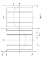
- FIG. 3 shows a graph of the modulation of the width of the alternating polarity voltage pulses, which are supplied to the coil in each oscillation period of the moving mass for the implementation of the training method. according to the invention.
- This pulse width modulation is preferably identical in all the periods of oscillation until the end of the vibration of the vibrating device.
- This graph represents a period T 0 oscillation defined in angular form from 0 to 360 °.
- the sign inversion of each pulse is preferably determined by a specific angle between 0 and 360 ° since the measured resonant frequency may vary depending on the wearing conditions of the portable object. However, after the frequency measurement of the second phase, this resonance frequency is determined in principle for the entire vibration duration of the vibrating device.
- the vibrating device For driving the vibrating device according to the invention, it is used a method of eliminating harmonics of order greater than 1 and controlling the amplitude of the fundamental. Indeed, as mentioned above, the harmonics of order 3, 5, 7 and higher are at the origin of the losses in the coil and in iron parts of the vibrating device. By eliminating these harmonics and controlling the so-defined fundamental frequency voltage wave, one tends to approach a sinusoidal voltage of desired amplitude.
- the sign inversions for the successive rectangular pulses occur for the angle values ⁇ 1, ⁇ 2 and ⁇ 3, and (180 ° - ⁇ 3), (180 ° - ⁇ 2) and ( 180 ° - ⁇ 1).
- the second half period is defined on the basis of the angles of the first half period but with pulses of inverse polarity. This waveform makes it possible to eliminate a discrete number of harmonics while imposing a determined amplitude of the fundamental frequency wave.
- the amplitude of the fundamental that is to say the amplitude of the sine wave defined by the modulation of width of the rectangular pulses of alternating polarity voltage
- the tables of the angles determined according to the amplitude of the desired fundamental it is easy to calculate time values of the width of each pulse by means of a rule of three as a function of the value of the frequency of oscillation.
- This oscillation frequency can be in a range of 125 to 140 Hz, preferably of the order of 135 Hz for example.
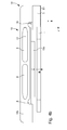
- FIGs 4a and 4b show an embodiment of the vibrating device 10 for carrying out the training method according to the invention.
- the vibrating device presented is of the half Voice Coil type.
- the vibrating device 10 firstly comprises an annular flat coil L, which is fixed at the edge to a non-magnetic structure 5, beneath which two connection terminals B1 and B2 of the coil appear.
- the device further comprises a mobile mass 13a, 13b, 6 and 15 composed of a magnetic structure which is connected to the non-magnetic structure without mechanical contact with the coil by means of a spring element 14.
- the magnetic structure of the mobile mass comprises a ferromagnetic plate 6 on which are fixed two permanent magnets 13a and 13b adjacent direction of opposite magnetization opposite respectively two diametrically opposite portions of the coil.
- the magnets generate a magnetic field B , which is conducted in the ferromagnetic plate 6, in a direction along the Y axis.
- the current flowing in the coil portions is substantially perpendicular. to the magnetic field B in the direction of the Z axis.
- L in the directions represented 0+ and 0-.
- This complementary plate 15 may be made of a material such as brass or tungsten.
- the spring element 14, which holds the moving mass, comprises a base plate 14c fixed by two screws 17 via a non-magnetic plate 5 'to the non-magnetic structure 5, and two leaf springs 14a and 14b coming from with the base blade and disposed on two opposite sides of the base blade.
- the leaf springs 14a and 14b are arranged perpendicular to the base plate 14c, so that the cross section forms a U.
- the ferromagnetic plate 6 and the complementary plate 15 are placed between the leaf springs 14a and 14b with or without direct contact with each leaf spring.
- the height of the ferromagnetic plate 6 and the complementary plate 15 is less than the height of each leaf spring 14a and 14b.
- the spring blades 14a and 14b may each comprise two longitudinal through slots 8, which are dimensioned to adjust a theoretical resonance frequency of the vibrating device. By this adjustment of this frequency, the driving circuit of the vibrating device can be of relatively simple design.
- the inductance of the coil is much smaller than in the case of a coil mounted on a ferromagnetic yoke as explained in document EP 0 625 738.
- the value of the inductance can be of the order of 1 to 1.5 mH, whereas in the case of a coil mounted on a ferromagnetic yoke, this inductance value can be of the order of 50 mH.
- the induced voltage mainly related to the magnet-coil mutual flux is also lower with this low inductance, and a possible overvoltage of the coil in the measurement phase of the oscillation frequency can be much smaller without damaging the drive circuit .
- the dimensions of such a vibrating device to equip such a wristwatch can be 10 mm long, 4 mm wide and 2 mm high.
- the driving method can also be applied to a vibrating device as presented in document EP 0 625 738.
- a vibrating device As presented in document EP 0 625 738, it is thus not necessary to provide the driving circuit of any filter element, which simplifies the realization of said circuit and reduces the power consumption.
Priority Applications (7)
| Application Number | Priority Date | Filing Date | Title |
|---|---|---|---|
| EP04106436A EP1669820A1 (de) | 2004-12-09 | 2004-12-09 | Verfahren zum Antrieb einer Schwingungsvorrichtung für ein tragbares Gerät, mit einer Spule und einer bewegbaren Masse |
| US11/289,561 US7385362B2 (en) | 2004-12-09 | 2005-11-30 | Method for driving a vibrating device for a portable object that comprises a coil and a moving mass |
| JP2005347512A JP4795008B2 (ja) | 2004-12-09 | 2005-12-01 | コイルと可動体とを有する携帯機器用振動装置の駆動方法 |
| DE602005026621T DE602005026621D1 (de) | 2004-12-09 | 2005-12-08 | Verfahren zum Antrieb einer Schwingungsvorrichtungr bewegbaren Masse |
| EP20050111845 EP1669821B1 (de) | 2004-12-09 | 2005-12-08 | Verfahren zum Antrieb einer Schwingungsvorrichtung für ein tragbares Gerät, mit einer Spule und einer bewegbaren Masse |
| CN2005101294569A CN1787347B (zh) | 2004-12-09 | 2005-12-08 | 驱动包括线圈和移动块的便携式物体用振动器件的方法 |
| HK06111918.0A HK1091602A1 (en) | 2004-12-09 | 2006-10-27 | Method for driving a vibrating device for a portable object that comprises a coil and a moving mass |
Applications Claiming Priority (1)
| Application Number | Priority Date | Filing Date | Title |
|---|---|---|---|
| EP04106436A EP1669820A1 (de) | 2004-12-09 | 2004-12-09 | Verfahren zum Antrieb einer Schwingungsvorrichtung für ein tragbares Gerät, mit einer Spule und einer bewegbaren Masse |
Publications (1)
| Publication Number | Publication Date |
|---|---|
| EP1669820A1 true EP1669820A1 (de) | 2006-06-14 |
Family
ID=34930026
Family Applications (1)
| Application Number | Title | Priority Date | Filing Date |
|---|---|---|---|
| EP04106436A Withdrawn EP1669820A1 (de) | 2004-12-09 | 2004-12-09 | Verfahren zum Antrieb einer Schwingungsvorrichtung für ein tragbares Gerät, mit einer Spule und einer bewegbaren Masse |
Country Status (6)
| Country | Link |
|---|---|
| US (1) | US7385362B2 (de) |
| EP (1) | EP1669820A1 (de) |
| JP (1) | JP4795008B2 (de) |
| CN (1) | CN1787347B (de) |
| DE (1) | DE602005026621D1 (de) |
| HK (1) | HK1091602A1 (de) |
Families Citing this family (6)
| Publication number | Priority date | Publication date | Assignee | Title |
|---|---|---|---|---|
| US8314586B2 (en) * | 2006-10-31 | 2012-11-20 | Koninklijke Philipes Electronics N.V. | System for adapting the resonant operation of a personal care appliance during the lifetime thereof |
| FR2940892B1 (fr) * | 2009-01-09 | 2011-04-08 | Quo Vadis | Piece de chaussure munie d'un dispositif vibratoire |
| JP5470154B2 (ja) * | 2010-05-13 | 2014-04-16 | セミコンダクター・コンポーネンツ・インダストリーズ・リミテッド・ライアビリティ・カンパニー | リニア振動モータの駆動制御回路 |
| GB201222882D0 (en) | 2012-12-19 | 2013-01-30 | Univ Leeds | Ultrasound generation |
| EP3412946A1 (de) * | 2017-06-09 | 2018-12-12 | Andreas Stihl AG & Co. KG | Verfahren zur ansteuerung eines elektromagnetischen ventils und elektromagnetisches ventil |
| WO2019003339A1 (ja) | 2017-06-28 | 2019-01-03 | 富士通株式会社 | 駆動制御装置、電子機器、及び駆動制御方法 |
Citations (5)
| Publication number | Priority date | Publication date | Assignee | Title |
|---|---|---|---|---|
| US5436622A (en) * | 1993-07-06 | 1995-07-25 | Motorola, Inc. | Variable frequency vibratory alert method and structure |
| EP0938034A1 (de) * | 1998-02-20 | 1999-08-25 | Asulab S.A. | Nichthörbare Alarmvorrichtung |
| EP0952663A2 (de) * | 1998-04-23 | 1999-10-27 | Matsushita Electric Works, Ltd. | Treiberstufe für einen schwingenden Aktuator |
| WO2000038891A2 (de) * | 1998-12-23 | 2000-07-06 | Braun Gmbh | Antriebseinrichtung für oszillierende elektrische produkte des persönlichen bedarfs, insbesondere trockenrasierer |
| WO2002046847A1 (fr) * | 2000-12-05 | 2002-06-13 | Eta Sa Manufacture Horlogere Suisse | Procede d'entretien des oscillations d'un dispositif vibrant et dispositif vibrant mettant en oeuvre ce procede |
Family Cites Families (3)
| Publication number | Priority date | Publication date | Assignee | Title |
|---|---|---|---|---|
| CN87217183U (zh) * | 1987-12-29 | 1988-11-09 | 河南省科学院科研器材厂 | 一种低电源电压脉冲超声波发生器 |
| DE69839114T2 (de) * | 1998-02-20 | 2009-02-05 | Asulab S.A. | Nichthörbare Alarmvorrichtung |
| WO2001072435A1 (fr) * | 2000-03-28 | 2001-10-04 | Iwaki Electronics Co., Ltd. | Vibreur et telephone portable equipe d'un tel dispositif |
-
2004
- 2004-12-09 EP EP04106436A patent/EP1669820A1/de not_active Withdrawn
-
2005
- 2005-11-30 US US11/289,561 patent/US7385362B2/en not_active Expired - Fee Related
- 2005-12-01 JP JP2005347512A patent/JP4795008B2/ja not_active Expired - Fee Related
- 2005-12-08 DE DE602005026621T patent/DE602005026621D1/de active Active
- 2005-12-08 CN CN2005101294569A patent/CN1787347B/zh not_active Expired - Fee Related
-
2006
- 2006-10-27 HK HK06111918.0A patent/HK1091602A1/xx not_active IP Right Cessation
Patent Citations (5)
| Publication number | Priority date | Publication date | Assignee | Title |
|---|---|---|---|---|
| US5436622A (en) * | 1993-07-06 | 1995-07-25 | Motorola, Inc. | Variable frequency vibratory alert method and structure |
| EP0938034A1 (de) * | 1998-02-20 | 1999-08-25 | Asulab S.A. | Nichthörbare Alarmvorrichtung |
| EP0952663A2 (de) * | 1998-04-23 | 1999-10-27 | Matsushita Electric Works, Ltd. | Treiberstufe für einen schwingenden Aktuator |
| WO2000038891A2 (de) * | 1998-12-23 | 2000-07-06 | Braun Gmbh | Antriebseinrichtung für oszillierende elektrische produkte des persönlichen bedarfs, insbesondere trockenrasierer |
| WO2002046847A1 (fr) * | 2000-12-05 | 2002-06-13 | Eta Sa Manufacture Horlogere Suisse | Procede d'entretien des oscillations d'un dispositif vibrant et dispositif vibrant mettant en oeuvre ce procede |
Also Published As
| Publication number | Publication date |
|---|---|
| CN1787347A (zh) | 2006-06-14 |
| CN1787347B (zh) | 2010-11-03 |
| JP4795008B2 (ja) | 2011-10-19 |
| US20060144173A1 (en) | 2006-07-06 |
| US7385362B2 (en) | 2008-06-10 |
| DE602005026621D1 (de) | 2011-04-14 |
| JP2006159188A (ja) | 2006-06-22 |
| HK1091602A1 (en) | 2007-01-19 |
Similar Documents
| Publication | Publication Date | Title |
|---|---|---|
| EP2463732B1 (de) | Schlagwerkmechanismus einer Armbanduhr oder einer Spieluhr | |
| CH321957A (fr) | Dispositif moteur à impulsions électromanétiques applicable notamment aux instruments horaires | |
| FR2527345A1 (fr) | Dispositif de basculement du miroir secondaire d'un telescope | |
| FR2501314A1 (fr) | Palier electromagnetique actif redondant | |
| CH688952B5 (fr) | Circuit d'alimentation pour une feuille électroluminescente. | |
| EP2496990A1 (de) | Einstellungselement für eine armbanduhr sowie uhr mit einem solchen einstellungselement | |
| EP1521142A1 (de) | Uhr mit einem mechanischen Uhrwerk, das mit einem elektronischen Regulator gekoppelt ist | |
| EP1669820A1 (de) | Verfahren zum Antrieb einer Schwingungsvorrichtung für ein tragbares Gerät, mit einer Spule und einer bewegbaren Masse | |
| EP2239842A1 (de) | Verstärkerschaltkreis mit schwachem Phasengeräusch | |
| FR2492607A1 (fr) | Dispositif de commande de vitesse pour un moteur a courant continu | |
| FR2701105A1 (fr) | Dispositif de déminage. | |
| EP1669821B1 (de) | Verfahren zum Antrieb einer Schwingungsvorrichtung für ein tragbares Gerät, mit einer Spule und einer bewegbaren Masse | |
| EP1674165A1 (de) | Rüttelvorrichtung für einen tragbaren Gegenstand mit Schutzmitteln gegen mechanische Stö e | |
| EP1342132B1 (de) | Verfahren zum instandhalten der oszillation einer vibrierenden vorrichtung und vibrierende vorrichtung die dieses verfahren anwendet | |
| EP1659676A1 (de) | Vibrator für ein tragbares Objekt | |
| JP3833607B2 (ja) | 振動発生器 | |
| EP3556006A1 (de) | Piezoelektrischer aktuatorsteuerungsvorrichtung für kapazitive lasten | |
| FR2672712A1 (fr) | Deflecteur alternatif de lumiere laser pour lecteur de codes a barres. | |
| FR2488398A1 (fr) | Debitmetre electromagnetique | |
| EP4325304A1 (de) | Nichtakustischer elektromagnetischer alarm | |
| CH719962A2 (fr) | Alarme vibratoire non sonore électromagnétique. | |
| FR2878335A1 (fr) | Capteur de courant utilisant un pont de capacites | |
| FR2773709A1 (fr) | Appareil et procede de production de stimuli de points d'acuponcture | |
| CH715145A2 (fr) | Montre thermoélectrique testable en production ou service après-vente. | |
| FR3109482A1 (fr) | Cellules elementaires d’un moteur electrique et moteur electrique correspondant |
Legal Events
| Date | Code | Title | Description |
|---|---|---|---|
| PUAI | Public reference made under article 153(3) epc to a published international application that has entered the european phase |
Free format text: ORIGINAL CODE: 0009012 |
|
| AK | Designated contracting states |
Kind code of ref document: A1 Designated state(s): AT BE BG CH CY CZ DE DK EE ES FI FR GB GR HU IE IS IT LI LT LU MC NL PL PT RO SE SI SK TR |
|
| AX | Request for extension of the european patent |
Extension state: AL BA HR LV MK YU |
|
| AKX | Designation fees paid | ||
| REG | Reference to a national code |
Ref country code: DE Ref legal event code: 8566 |
|
| STAA | Information on the status of an ep patent application or granted ep patent |
Free format text: STATUS: THE APPLICATION IS DEEMED TO BE WITHDRAWN |
|
| 18D | Application deemed to be withdrawn |
Effective date: 20061215 |