EP1669618A2 - Bearing arrangement for spindle nut - Google Patents
Bearing arrangement for spindle nut Download PDFInfo
- Publication number
- EP1669618A2 EP1669618A2 EP05019315A EP05019315A EP1669618A2 EP 1669618 A2 EP1669618 A2 EP 1669618A2 EP 05019315 A EP05019315 A EP 05019315A EP 05019315 A EP05019315 A EP 05019315A EP 1669618 A2 EP1669618 A2 EP 1669618A2
- Authority
- EP
- European Patent Office
- Prior art keywords
- spindle nut
- bearing
- bearing bush
- wall
- holder
- Prior art date
- Legal status (The legal status is an assumption and is not a legal conclusion. Google has not performed a legal analysis and makes no representation as to the accuracy of the status listed.)
- Granted
Links
Images

Classifications
-
- B—PERFORMING OPERATIONS; TRANSPORTING
- B60—VEHICLES IN GENERAL
- B60N—SEATS SPECIALLY ADAPTED FOR VEHICLES; VEHICLE PASSENGER ACCOMMODATION NOT OTHERWISE PROVIDED FOR
- B60N2/00—Seats specially adapted for vehicles; Arrangement or mounting of seats in vehicles
- B60N2/02—Seats specially adapted for vehicles; Arrangement or mounting of seats in vehicles the seat or part thereof being movable, e.g. adjustable
- B60N2/04—Seats specially adapted for vehicles; Arrangement or mounting of seats in vehicles the seat or part thereof being movable, e.g. adjustable the whole seat being movable
- B60N2/06—Seats specially adapted for vehicles; Arrangement or mounting of seats in vehicles the seat or part thereof being movable, e.g. adjustable the whole seat being movable slidable
- B60N2/067—Seats specially adapted for vehicles; Arrangement or mounting of seats in vehicles the seat or part thereof being movable, e.g. adjustable the whole seat being movable slidable by linear actuators, e.g. linear screw mechanisms
-
- F—MECHANICAL ENGINEERING; LIGHTING; HEATING; WEAPONS; BLASTING
- F16—ENGINEERING ELEMENTS AND UNITS; GENERAL MEASURES FOR PRODUCING AND MAINTAINING EFFECTIVE FUNCTIONING OF MACHINES OR INSTALLATIONS; THERMAL INSULATION IN GENERAL
- F16C—SHAFTS; FLEXIBLE SHAFTS; ELEMENTS OR CRANKSHAFT MECHANISMS; ROTARY BODIES OTHER THAN GEARING ELEMENTS; BEARINGS
- F16C27/00—Elastic or yielding bearings or bearing supports, for exclusively rotary movement
- F16C27/06—Elastic or yielding bearings or bearing supports, for exclusively rotary movement by means of parts of rubber or like materials
- F16C27/063—Sliding contact bearings
-
- F—MECHANICAL ENGINEERING; LIGHTING; HEATING; WEAPONS; BLASTING
- F16—ENGINEERING ELEMENTS AND UNITS; GENERAL MEASURES FOR PRODUCING AND MAINTAINING EFFECTIVE FUNCTIONING OF MACHINES OR INSTALLATIONS; THERMAL INSULATION IN GENERAL
- F16C—SHAFTS; FLEXIBLE SHAFTS; ELEMENTS OR CRANKSHAFT MECHANISMS; ROTARY BODIES OTHER THAN GEARING ELEMENTS; BEARINGS
- F16C27/00—Elastic or yielding bearings or bearing supports, for exclusively rotary movement
- F16C27/08—Elastic or yielding bearings or bearing supports, for exclusively rotary movement primarily for axial load, e.g. for vertically-arranged shafts
-
- F—MECHANICAL ENGINEERING; LIGHTING; HEATING; WEAPONS; BLASTING
- F16—ENGINEERING ELEMENTS AND UNITS; GENERAL MEASURES FOR PRODUCING AND MAINTAINING EFFECTIVE FUNCTIONING OF MACHINES OR INSTALLATIONS; THERMAL INSULATION IN GENERAL
- F16H—GEARING
- F16H25/00—Gearings comprising primarily only cams, cam-followers and screw-and-nut mechanisms
- F16H25/18—Gearings comprising primarily only cams, cam-followers and screw-and-nut mechanisms for conveying or interconverting oscillating or reciprocating motions
- F16H25/20—Screw mechanisms
- F16H25/2003—Screw mechanisms with arrangements for taking up backlash
-
- F—MECHANICAL ENGINEERING; LIGHTING; HEATING; WEAPONS; BLASTING
- F16—ENGINEERING ELEMENTS AND UNITS; GENERAL MEASURES FOR PRODUCING AND MAINTAINING EFFECTIVE FUNCTIONING OF MACHINES OR INSTALLATIONS; THERMAL INSULATION IN GENERAL
- F16H—GEARING
- F16H25/00—Gearings comprising primarily only cams, cam-followers and screw-and-nut mechanisms
- F16H25/18—Gearings comprising primarily only cams, cam-followers and screw-and-nut mechanisms for conveying or interconverting oscillating or reciprocating motions
- F16H25/20—Screw mechanisms
- F16H25/24—Elements essential to such mechanisms, e.g. screws, nuts
-
- F—MECHANICAL ENGINEERING; LIGHTING; HEATING; WEAPONS; BLASTING
- F16—ENGINEERING ELEMENTS AND UNITS; GENERAL MEASURES FOR PRODUCING AND MAINTAINING EFFECTIVE FUNCTIONING OF MACHINES OR INSTALLATIONS; THERMAL INSULATION IN GENERAL
- F16H—GEARING
- F16H57/00—General details of gearing
- F16H57/02—Gearboxes; Mounting gearing therein
- F16H57/021—Shaft support structures, e.g. partition walls, bearing eyes, casing walls or covers with bearings
- F16H57/022—Adjustment of gear shafts or bearings
- F16H2057/0221—Axial adjustment
-
- Y—GENERAL TAGGING OF NEW TECHNOLOGICAL DEVELOPMENTS; GENERAL TAGGING OF CROSS-SECTIONAL TECHNOLOGIES SPANNING OVER SEVERAL SECTIONS OF THE IPC; TECHNICAL SUBJECTS COVERED BY FORMER USPC CROSS-REFERENCE ART COLLECTIONS [XRACs] AND DIGESTS
- Y10—TECHNICAL SUBJECTS COVERED BY FORMER USPC
- Y10T—TECHNICAL SUBJECTS COVERED BY FORMER US CLASSIFICATION
- Y10T74/00—Machine element or mechanism
- Y10T74/18—Mechanical movements
- Y10T74/18568—Reciprocating or oscillating to or from alternating rotary
- Y10T74/18576—Reciprocating or oscillating to or from alternating rotary including screw and nut
- Y10T74/18728—Backlash
-
- Y—GENERAL TAGGING OF NEW TECHNOLOGICAL DEVELOPMENTS; GENERAL TAGGING OF CROSS-SECTIONAL TECHNOLOGIES SPANNING OVER SEVERAL SECTIONS OF THE IPC; TECHNICAL SUBJECTS COVERED BY FORMER USPC CROSS-REFERENCE ART COLLECTIONS [XRACs] AND DIGESTS
- Y10—TECHNICAL SUBJECTS COVERED BY FORMER USPC
- Y10T—TECHNICAL SUBJECTS COVERED BY FORMER US CLASSIFICATION
- Y10T74/00—Machine element or mechanism
- Y10T74/19—Gearing
- Y10T74/19623—Backlash take-up
-
- Y—GENERAL TAGGING OF NEW TECHNOLOGICAL DEVELOPMENTS; GENERAL TAGGING OF CROSS-SECTIONAL TECHNOLOGIES SPANNING OVER SEVERAL SECTIONS OF THE IPC; TECHNICAL SUBJECTS COVERED BY FORMER USPC CROSS-REFERENCE ART COLLECTIONS [XRACs] AND DIGESTS
- Y10—TECHNICAL SUBJECTS COVERED BY FORMER USPC
- Y10T—TECHNICAL SUBJECTS COVERED BY FORMER US CLASSIFICATION
- Y10T74/00—Machine element or mechanism
- Y10T74/19—Gearing
- Y10T74/1987—Rotary bodies
- Y10T74/19893—Sectional
- Y10T74/19898—Backlash take-up
- Y10T74/19902—Screw and nut
Definitions
- the invention relates to a spindle nut bearing arrangement in which a spindle nut is mounted with its end face rotatable about the longitudinal axis in a wall of a housing. Through the wall passes through a through hole to pass a shaft through the wall and through a through hole in the spindle nut and in engagement with the spindle nut.
- the wall is the wall of a housing in which the spindle nut is received and which is designed as a gear housing of a spindle drive.
- a disadvantage of such arrangements is that there is usually a distance between the end faces of the spindle nut and the adjacent walls, so that the spindle nut in the housing in the axial direction of the spindle nut has undesirable play.
- the object of the invention is to provide a spindle nut bearing assembly, which allows a backlash-free as possible storage of the spindle nut in the housing or between two walls of a housing.
- a spindle nut bearing arrangement with a wall having a wall width and a passage opening through the wall, a bearing bush which leads in the axial direction while leaving a clearance having a length greater than the width of the wall through the through opening, and can be moved in the axial direction is preferred is mounted in the passage opening, a spindle nut whose end side on a first end side of the bearing bush inside the wall rests, and a holder, which supports a second end face of the bearing bush against the spindle nut, wherein the spindle nut is acted upon elastically in the direction away from the wall.
- the bearing bush is axially movable.
- a spindle nut bearing arrangement is preferred in which an elastic element is arranged between the holder and the second end face of the bearing bush and biases the bearing bush against the spindle nut.
- a spindle nut bearing arrangement is preferred in which an elastic element is arranged between the bearing bush and the spindle nut and biases the spindle nut away from the bearing bush.
- a spindle nut bearing arrangement is preferred in which the elastic element consists of an elastomer.
- a spindle nut bearing arrangement is preferred in which the bearing bush has collars on the front side, wherein the length of the bearing bush extends between the collars.
- a spindle nut bearing arrangement is preferred in which the wall is a housing wall of a housing for receiving the spindle nut and the holder is a spindle drive holder.
- a spindle nut bearing arrangement is preferred, in which the spindle nut is supported on both sides by such an arrangement.
- a spindle nut bearing arrangement is preferred in which the bearing bush consists of two cylindrical bearing bush elements consists, of which the first bearing bush element is rotatably mounted with its cylindrical outer circumference in the cylindrical inner periphery of the second bearing bush element.
- a spindle nut bearing arrangement is preferred in which one or both of the bearing bush elements have a collar.
- a spindle nut bearing arrangement is preferred, in which a shaft passage opening leads to the passage of a spindle shaft as a result of the arrangement consisting of holder, bearing bush and elastic element.
- a spindle nut bearing arrangement is preferred, in which the holder consists of an elastic material and biases the bearing bush against the spindle nut.
- FIG. 1 shows a spindle nut bearing arrangement in partial sectional view.
- a spindle nut SM between two walls W, of which only one is sketched, stored, wherein the spindle nut SM is mounted rotatably about its longitudinal axis X.
- Through the wall W performs a through-hole WO through.
- a bearing bush L is inserted, which rests with its first end face S1 on an opposite end face SMS of the spindle nut SM.
- the bushing L has the front side in each case a collar K, wherein optionally one or both of the collar K can also be omitted.
- a length l of the bushing L in the axial direction i. in the direction in which the bearing bushing L passes through the passage opening WO, is greater than a width b of the wall W.
- the length 1 is the distance between the two collars K.
- a holder H At a second end face S2 of the bearing bush L or at the corresponding second collar K is a holder H with the interposition of an elastic element E.
- the holder H is biased relative to the wall W of the housing in the axial direction to the spindle nut SM.
- the bearing bush L is elastically biased with its first face S1 against the face SMS of the spindle nut SM, which is compensated by the game ⁇ any existing game between the face SMS of the spindle nut SM and the inside surface of the wall W due to the bias.
- the face SMS of the spindle nut SM and the inside of the wall W a distance, but it is not a distance which allows movement of the spindle nut SM in the axial direction, so a free play.
- the spindle nut SM Due to the design of the elastic element E in particular an elastomer, the spindle nut SM is elastically supported relative to the wall W in the axial direction.
- a shaft passage opening O passes through the entire arrangement along the central axis of rotation X, so that a spindle shaft SW can be inserted through the holder H, the elastic element E and the bearing bush L into the spindle nut SM.
- Fig. 2 shows schematically a spindle nut SM, which is mounted in its axial direction X on both sides with such a spindle nut bearing assembly in two walls W of a housing G.
- the holder H spans with two corresponding arms the arrangement of one per side elastic element E, a bearing bushing L and the spindle nut inserted therebetween SM. Due to the fact that the length 1 of the two bearing bushes which can be adjusted in the axial direction X is greater than the corresponding widths b of the two walls W, the spindle nut SM is supported without play within the housing G despite a spacing of its end faces SMS from the inner sides of the walls W.
- the bearing bushing L may be formed with only one collar K or no collar K at the front end portions to introduce the bushing L in a through hole WO in the wall W, when the diameter of the through hole WO smaller than the outer diameter of the corresponding Collar K is formed. Also possible is a slot-shaped passage opening from a side wall of the wall W up to the storage area for the bearing bush L. formed portion to use a bearing bush L with two collar K in the bearing section can.
- the two bearing bush elements L1, L2 both consist of a cylindrical section, wherein in the axial direction X, the length 1 corresponds to at least one of the bearing bush elements L2 of length 1 of the bearing bush L in the axial direction X.
- the other bearing bush element L1 may in particular have a shorter length.
- the other, first bushing element L1 has an outer diameter of the cylindrical portion, which is smaller or preferably almost equal to the inner diameter of the cylindrical portion of the second bearing sleeve element L2, so that the two bearing bush elements L1, L2 can be put together and thereby rotate about their longitudinal axis to each other , This allows a reduction in the frictional resistance in a rotation of the spindle nut SM between the bearing bush L and the wall of the through hole WO in the wall W.
- Such an arrangement allows easy mounting of the bearing bush L by the two bearing bush elements L1, L2 from the two sides of the Wall W from being inserted and plugged into the through hole WO.
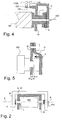
- Fig. 4 shows an example mounting possibility of the holder H directly to another wall GW of the housing.
- the further wall GW is a wall GW, which extends parallel to the axis of rotation of the spindle nut SM.
- the holder H is bent away from the bearing portion and extends parallel to the further wall GW.
- this has a longitudinal slot HS, through which the threaded shank of a screw HSR is guided to screw the screw HSR in a threaded bore GB of the further wall GW.
- this makes possible an alignment of the holder H in the axial direction X and in particular a biasing with a desired voltage against the arrangement of elastic element E, bearing bushing L and spindle nut SM.
- this holder H is thus a housing directly associated with the holder and not a holder H, which is also designed as a holder for the spindle nut SM and the entire housing to an external component.
- Fig. 5 shows a further exemplary arrangement of the holder H on the wall W of the housing.
- the holder H itself consists of such an elastic material that the holder H presses with its inside wall directly with a chip force F against the bearing bush L in the direction of the spindle nut SM.
- the holder H is correspondingly attached directly to the wall W itself, for example, fastened by means of a screw or soldered connection.
- FIG. 6 shows an alternative embodiment of the bearing bush L.
- This bearing bush L differs from the two-part bearing bush L sketched in FIG. 3 in that between the walls of the end faces S1, S2 in the interior an elastic element E *, in particular in the form of a helical spring , is used.
- This elastic element E * pushes apart the two bearing bush elements L 1, L 2 and thus assumes the function of the elastic element E used at the end side of the bearing bush L in the overall arrangement according to, for example, FIG. 1.
Abstract
Description
Die Erfindung bezieht sich auf eine Spindelmutter-Lageranordnung, bei welcher eine Spindelmutter mit ihrer Stirnseite um die Längsachse rotierbar in einer Wandung eines Gehäuses gelagert ist. Durch die Wandung führt eine Durchgangsöffnung hindurch, um eine Welle durch die Wandung und durch eine Durchgangsöffnung in der Spindelmutter sowie in Eingriff mit der Spindelmutter hindurchzuführen. Die Wandung ist dabei die Wandung eines Gehäuses, in welchem die Spindelmutter aufgenommen ist und welches als Getriebegehäuse eines Spindelantriebs ausgebildet ist.The invention relates to a spindle nut bearing arrangement in which a spindle nut is mounted with its end face rotatable about the longitudinal axis in a wall of a housing. Through the wall passes through a through hole to pass a shaft through the wall and through a through hole in the spindle nut and in engagement with the spindle nut. The wall is the wall of a housing in which the spindle nut is received and which is designed as a gear housing of a spindle drive.
Nachteilhaft bei solchen Anordnungen ist, dass üblicherweise zwischen den Stirnseiten der Spindelmutter und den benachbarten Wandungen ein Abstand besteht, so dass die Spindelmutter im Gehäuse in axialer Richtung der Spindelmutter unerwünschtes Spiel hat.A disadvantage of such arrangements is that there is usually a distance between the end faces of the spindle nut and the adjacent walls, so that the spindle nut in the housing in the axial direction of the spindle nut has undesirable play.
Die Aufgabe der Erfindung besteht darin, eine Spindelmutter-Lageranordnung vorzuschlagen, welche eine möglichst spielfreie Lagerung der Spindelmutter in dem Gehäuse bzw. zwischen zwei Wandungen eines Gehäuses ermöglicht.The object of the invention is to provide a spindle nut bearing assembly, which allows a backlash-free as possible storage of the spindle nut in the housing or between two walls of a housing.
Diese Aufgabe wird durch die Spindelmutter-Lageranordnung mit den Merkmalen des Patentanspruchs 1 gelöst.This object is achieved by the spindle nut bearing arrangement having the features of
Bevorzugt wird demgemäss eine Spindelmutter-Lageranordnung mit einer Wandung mit einer Wandungsbreite und einer Durchgangsöffnung durch die Wandung hindurch, einer Lagerbuchse, welche in axialer Richtung unter Belassung eines Spiels mit einer Länge größer als der Breite der Wandung durch die Durchgangsöffnung führt und in axialer Richtung bewegbar in der Durchgangsöffnung gelagert ist, einer Spindelmutter, deren Stirnseite an einer ersten Stirnseite der Lagerbuchse innenseitig der Wandung anliegt, und einer Halterung, welche eine zweite Stirnseite der Lagerbuchse gegen die Spindelmutter abstützt, wobei die Spindelmutter in Richtung von der Wandung weg elastisch beaufschlagt ist. Erfindungsgemäß ist die Lagerbuchse axial beweglich.Accordingly, a spindle nut bearing arrangement with a wall having a wall width and a passage opening through the wall, a bearing bush which leads in the axial direction while leaving a clearance having a length greater than the width of the wall through the through opening, and can be moved in the axial direction is preferred is mounted in the passage opening, a spindle nut whose end side on a first end side of the bearing bush inside the wall rests, and a holder, which supports a second end face of the bearing bush against the spindle nut, wherein the spindle nut is acted upon elastically in the direction away from the wall. According to the bearing bush is axially movable.
Vorteilhafte Ausgestaltungen sind Gegenstand abhängiger Ansprüche.Advantageous embodiments are the subject of dependent claims.
Bevorzugt wird insbesondere eine Spindelmutter-Lageranordnung, bei der ein elastisches Element zwischen der Halterung und der zweiten Stirnseite der Lagerbuchse angeordnet ist und die Lagerbuchse gegen die Spindelmutter spannt.In particular, a spindle nut bearing arrangement is preferred in which an elastic element is arranged between the holder and the second end face of the bearing bush and biases the bearing bush against the spindle nut.
Bevorzugt wird insbesondere eine Spindelmutter-Lageranordnung, bei der ein elastisches Element zwischen der Lagerbuchse und der Spindelmutter angeordnet ist und die Spindelmutter von der Lagerbuchse weg spannt.In particular, a spindle nut bearing arrangement is preferred in which an elastic element is arranged between the bearing bush and the spindle nut and biases the spindle nut away from the bearing bush.
Bevorzugt wird insbesondere eine Spindelmutter-Lageranordnung, bei der das elastische Element aus einem Elastomer besteht.In particular, a spindle nut bearing arrangement is preferred in which the elastic element consists of an elastomer.
Bevorzugt wird insbesondere eine Spindelmutter-Lageranordnung, bei der die Lagerbuche stirnseitig Kragen aufweist, wobei die Länge der Lagerbuchse sich zwischen den Kragen erstreckt.In particular, a spindle nut bearing arrangement is preferred in which the bearing bush has collars on the front side, wherein the length of the bearing bush extends between the collars.
Bevorzugt wird insbesondere eine Spindelmutter-Lageranordnung, bei der die Wandung eine Gehäusewandung eines Gehäuses zur Aufnahme der Spindelmutter ist und die Halterung ein Spindelantriebhalter ist.In particular, a spindle nut bearing arrangement is preferred in which the wall is a housing wall of a housing for receiving the spindle nut and the holder is a spindle drive holder.
Bevorzugt wird insbesondere eine Spindelmutter-Lageranordnung, bei der die Spindelmutter beidseitig durch eine solche Anordnung gelagert ist.In particular, a spindle nut bearing arrangement is preferred, in which the spindle nut is supported on both sides by such an arrangement.
Bevorzugt wird insbesondere eine Spindelmutter-Lageranordnung, bei der die Lagerbuchse aus zwei zylindrischen Lagerbuchsenelementen besteht, von denen das erste Lagerbuchsenelement mit seinem zylindrischen Außenumfang im zylindrischen Innenumfang des zweiten Lagerbuchsenelements rotierfähig gelagert ist.In particular, a spindle nut bearing arrangement is preferred in which the bearing bush consists of two cylindrical bearing bush elements consists, of which the first bearing bush element is rotatably mounted with its cylindrical outer circumference in the cylindrical inner periphery of the second bearing bush element.
Bevorzugt wird insbesondere eine Spindelmutter-Lageranordnung, bei der eines oder beide der Lagerbuchsenelemente einen Kragen aufweisen.In particular, a spindle nut bearing arrangement is preferred in which one or both of the bearing bush elements have a collar.
Bevorzugt wird insbesondere eine Spindelmutter-Lageranordnung, bei der durch die Anordnung aus Halterung, Lagerbuchse und elastischem Element eine Wellendurchtrittsöffnung zum Durchführen einer Spindelwelle führt.In particular, a spindle nut bearing arrangement is preferred, in which a shaft passage opening leads to the passage of a spindle shaft as a result of the arrangement consisting of holder, bearing bush and elastic element.
Bevorzugt wird insbesondere eine Spindelmutter-Lageranordnung, bei der die Halterung aus einem elastischen Material besteht und die Lagerbuchse gegen die Spindelmutter spannt.In particular, a spindle nut bearing arrangement is preferred, in which the holder consists of an elastic material and biases the bearing bush against the spindle nut.
Ein Ausführungsbeispiel der Erfindung wird nachfolgend anhand der Zeichnung näher erläutert. Dabei wird davon ausgegangen, dass die Spindelmutter-Lageranordnung vorzugsweise zur Sitzlängsverstellung in Kraftfahrzeugen eingesetzt ist. Es zeigen:
- Fig. 1
- eine Teilschnittansicht durch einen vergrößerten Ausschnitt einer Spindelmutter-Lageranordnung;
- Fig. 2
- schematisch eine aufgeschnittene Wandung eines Gehäuses mit Spindelmutter-Lageranordnungen in den gegenüberliegenden Wandungen und eine diese einspannenden Halterung;
- Fig. 3
- eine aus zwei Elementen zusammengesetzte Lagerbuchse;
- Fig. 4
- eine beispielhafte Befestigung der Halterung an dem Gehäuse;
- Fig. 5
- eine weitere beispielhafte Anordnung zur Befestigung der Halterung an dem Gehäuse; und
- Fig. 6
- eine alternative zweiteilig ausgebildete Lagerbuchse in Schnittansicht.
- Fig. 1
- a partial sectional view through an enlarged section of a spindle nut bearing assembly;
- Fig. 2
- schematically a cut-wall of a housing with spindle nut bearing assemblies in the opposite walls and a holder clamping them;
- Fig. 3
- a composite of two elements bearing bush;
- Fig. 4
- an exemplary attachment of the holder to the housing;
- Fig. 5
- another exemplary arrangement for attaching the holder to the housing; and
- Fig. 6
- an alternative two-piece bearing bush in a sectional view.
Fig.1 zeigt eine Spindelmutter-Lageranordnung in Teilschnittansicht. In üblicher Art und Weise ist eine Spindelmutter SM zwischen zwei Wandungen W, von denen nur eine skizziert ist, gelagert, wobei die Spindelmutter SM um ihre Längsachse X rotierbar gelagert ist. Durch die Wandung W führt eine Durchgangsöffnung WO hindurch.1 shows a spindle nut bearing arrangement in partial sectional view. In the usual way, a spindle nut SM between two walls W, of which only one is sketched, stored, wherein the spindle nut SM is mounted rotatably about its longitudinal axis X. Through the wall W performs a through-hole WO through.
In der Durchgangsöffnung WO ist eine Lagerbuchse L eingesetzt, welche mit ihrer ersten Stirnseite S1 an einer gegenüberliegenden Stirnseite SMS der Spindelmutter SM anliegt. Die Lagerbuchse L weist stirnseitig jeweils einen Kragen K auf, wobei gegebenenfalls einer oder beide der Kragen K auch entfallen können. Eine Länge l der Lagerbuchse L in axialer Richtung, d.h. in der Richtung, in der die Lagerbuchse L durch die Durchgangsöffnung'WO hindurchführt, ist dabei größer als eine Breite b der Wandung W. Bei der dargestellten Ausführungsform handelt es sich bei der Länge 1 um die Strecke zwischen den beiden Kragen K. Durch diese Anordnung verbleibt in axialer Richtung ein Spiel Δ entsprechend der Differenz aus der Länge 1 der Lagerbuchse L und der Breite b der Wandung W.In the through-hole WO, a bearing bush L is inserted, which rests with its first end face S1 on an opposite end face SMS of the spindle nut SM. The bushing L has the front side in each case a collar K, wherein optionally one or both of the collar K can also be omitted. A length l of the bushing L in the axial direction, i. in the direction in which the bearing bushing L passes through the passage opening WO, is greater than a width b of the wall W. In the illustrated embodiment, the
An einer zweiten Stirnseite S2 der Lagerbuchse L bzw. an deren entsprechendem zweiten Kragen K liegt unter Zwischenschaltung eines elastischen Elements E eine Halterung H an.At a second end face S2 of the bearing bush L or at the corresponding second collar K is a holder H with the interposition of an elastic element E.
Die Halterung H ist dabei relativ zu der Wandung W des Gehäuses in axialer Richtung zur Spindelmutter SM vorgespannt. Dadurch wird die Lagerbuchse L mit ihrer ersten Stirnseite S1 gegen die Stirnseite SMS der Spindelmutter SM elastisch vorgespannt, wobei durch das Spiel Δ ein eventuell vorhandenes Spiel zwischen der Stirnseite SMS der Spindelmutter SM und der innenseitigen Oberfläche der Wandung W aufgrund der Vorspannung ausgeglichen wird. Zwar bleibt gegebenenfalls zwischen der Stirnseite SMS der Spindelmutter SM und der Innenseite der Wandung W ein Abstand, jedoch handelt es sich nicht um einen Abstand, welcher eine Bewegung der Spindelmutter SM in axialer Richtung, also ein freies Spiel ermöglicht. Durch die Ausbildung des elastischen Elements E aus insbesondere einem Elastomer ist die Spindelmutter SM relativ zu der Wandung W in axialer Richtung elastisch abgestützt.The holder H is biased relative to the wall W of the housing in the axial direction to the spindle nut SM. Thus, the bearing bush L is elastically biased with its first face S1 against the face SMS of the spindle nut SM, which is compensated by the game Δ any existing game between the face SMS of the spindle nut SM and the inside surface of the wall W due to the bias. Although, if necessary, between the face SMS of the spindle nut SM and the inside of the wall W a distance, but it is not a distance which allows movement of the spindle nut SM in the axial direction, so a free play. Due to the design of the elastic element E in particular an elastomer, the spindle nut SM is elastically supported relative to the wall W in the axial direction.
Zum Einführen einer Spindelwelle SW führt durch die gesamte Anordnung längs der zentralen Rotationsachse X eine Wellendurchtrittsöffnung O hindurch, so dass eine Spindelwelle SW durch die Halterung H, das elastische Element E und die Lagerbuchse L hindurch in die Spindelmutter SM eingesetzt werden kann.For introducing a spindle shaft SW, a shaft passage opening O passes through the entire arrangement along the central axis of rotation X, so that a spindle shaft SW can be inserted through the holder H, the elastic element E and the bearing bush L into the spindle nut SM.
Fig. 2 stellt schematisch eine Spindelmutter SM dar, welche in ihrer axialen Richtung X beidseitig mit einer solchen Spindelmutter-Lageranordnung in zwei Wandungen W eines Gehäuses G gelagert ist. Die Halterung H umspannt dabei mit zwei entsprechenden Auslegern die Anordnung aus jeweils pro Seite einem elastischen Element E, einer Lagerbuchse L und der dazwischen eingesetzten Spindelmutter SM. Dadurch, dass die in axialer Richtung X verstellbare Länge 1 der beiden Lagerbuchsen größer als die entsprechenden Breiten b der beiden Wandungen W ist, ist die Spindelmutter SM trotz einer Beabstandung ihrer Stirnseiten SMS von den Innenseiten der Wandungen W spielfrei innerhalb des Gehäuses G gelagert.Fig. 2 shows schematically a spindle nut SM, which is mounted in its axial direction X on both sides with such a spindle nut bearing assembly in two walls W of a housing G. The holder H spans with two corresponding arms the arrangement of one per side elastic element E, a bearing bushing L and the spindle nut inserted therebetween SM. Due to the fact that the
Prinzipiell kann die Lagerbuchse L mit nur einem Kragen K oder ganz ohne Kragen K an den stirnseitigen Endabschnitten ausgebildet sein, um die Lagerbuchse L in eine Durchgangsöffnung WO in der Wandung W einführen zu können, wenn der Durchmesser der Durchgangsöffnung WO kleiner als der Außendurchmesser der entsprechenden Kragen K ausgebildet ist. Möglich ist auch eine schlitzförmige Durchgangsöffnung von einer Seitenwandung der Wandung W bis zu dem als Lagerbereich für die Lagerbuchse L ausgebildeten Abschnitt, um eine Lagerbusche L mit zwei Kragen K in den Lagerabschnitt einsetzen zu können.In principle, the bearing bushing L may be formed with only one collar K or no collar K at the front end portions to introduce the bushing L in a through hole WO in the wall W, when the diameter of the through hole WO smaller than the outer diameter of the corresponding Collar K is formed. Also possible is a slot-shaped passage opening from a side wall of the wall W up to the storage area for the bearing bush L. formed portion to use a bearing bush L with two collar K in the bearing section can.
Besonders bevorzugt mit Blick auf eine Durchgangsöffnung WO mit kleinerem Durchmesser als dem Außendurchmesser der Kragen K der Lagerbuchse L wird jedoch eine zweiteilige Lagerbuchse L mit einem ersten und einem zweiten Lagerbuchsenelement L1, L2, wie dies in Fig. 3 dargestellt ist. Die beiden Lagerbuchsenelemente L1, L2 bestehen beide aus einem zylinderförmigen Abschnitt, wobei in axialer Richtung X die Länge 1 zumindest eines der Lagerbuchsenelemente L2 der Länge 1 der Lagerbuchse L in axialer Richtung X entspricht. Das andere Lagerbuchsenelement L1 kann insbesondere eine kürzere Länge aufweisen. Das andere, erste Lagerbuchsenelement L1 weist einen Außendurchmesser des zylindrischen Abschnitts auf, welcher kleiner oder vorzugsweise nahezu gleich dem Innendurchmesser des zylindrischen Abschnitts des zweiten Lagerbuchsenelements L2 ist, so dass die beiden Lagerbuchsenelemente L1, L2 zusammengesteckt werden können und dabei um ihre Längsachse zueinander rotieren können. Dies ermöglicht eine Herabsetzung des Reibungswiderstands bei einer Rotation der Spindelmutter SM zwischen der Lagerbuchse L und der Wandung der Durchgangsöffnung WO in der Wandung W. Eine solche Anordnung ermöglicht eine einfache Montage der Lagerbuchse L, indem die beiden Lagerbuchsenelemente L1, L2 von den beiden Seiten der Wandung W aus in deren Durchgangsöffnung WO eingesetzt und zusammengesteckt werden.However, with particular regard to a passage opening WO with a smaller diameter than the outer diameter of the collar K of the bearing bush L, a two-part bearing bush L with a first and a second bearing bush element L1, L2, as shown in Fig. 3. The two bearing bush elements L1, L2 both consist of a cylindrical section, wherein in the axial direction X, the
Fig. 4 zeigt eine beispielhafte Befestigungsmöglichkeit der Halterung H direkt an einer weiteren Wandung GW des Gehäuses. Bei der weiteren Wandung GW handelt es sich um eine Wandung GW, welche sich parallel zur Rotationsachse der Spindelmutter SM erstreckt. Die Halterung H ist von dem Lagerabschnitt beabstandet gebogen und verläuft parallel zu der weiteren Wandung GW. Zur Befestigung der Halterung H weist diese einen Längsschlitz HS auf, durch welchen der Gewindeschaft einer Schraube HSR geführt wird, um die Schraube HSR in eine Gewindebohrung GB der weiteren Wandung GW einzuschrauben. Dies ermöglicht ein Ausrichten der Halterung H in axialer Richtung X und insbesondere ein Vorspannen mit einer gewünschten Spannung gegen die Anordnung aus elastischem Element E, Lagerbuchse L und Spindelmutter SM. Bei dieser Halterung H handelt es sich somit um eine dem Gehäuse direkt zugeordnete Halterung und nicht um eine Halterung H, welche zugleich als Halterung für die Spindelmutter SM und das gesamte Gehäuse an einer externen Komponente ausgebildet ist.Fig. 4 shows an example mounting possibility of the holder H directly to another wall GW of the housing. The further wall GW is a wall GW, which extends parallel to the axis of rotation of the spindle nut SM. The holder H is bent away from the bearing portion and extends parallel to the further wall GW. For fixing the holder H, this has a longitudinal slot HS, through which the threaded shank of a screw HSR is guided to screw the screw HSR in a threaded bore GB of the further wall GW. this makes possible an alignment of the holder H in the axial direction X and in particular a biasing with a desired voltage against the arrangement of elastic element E, bearing bushing L and spindle nut SM. In this holder H is thus a housing directly associated with the holder and not a holder H, which is also designed as a holder for the spindle nut SM and the entire housing to an external component.
Fig. 5 zeigt eine weitere beispielhafte Anordnung der Halterung H an der Wandung W des Gehäuses. Bei dieser Ausführungsform besteht die Halterung H selber aus einem derart elastischen Material, dass die Halterung H mit ihrer innenseitigen Wandung direkt mit einer Spankraft F gegen die Lagerbuchse L in Richtung der Spindelmutter SM drückt. Die Halterung H ist entsprechend direkt an der Wandung W selber befestigt, beispielsweise mittels einer Schraubverbindung oder Lötverbindung befestigt.Fig. 5 shows a further exemplary arrangement of the holder H on the wall W of the housing. In this embodiment, the holder H itself consists of such an elastic material that the holder H presses with its inside wall directly with a chip force F against the bearing bush L in the direction of the spindle nut SM. The holder H is correspondingly attached directly to the wall W itself, for example, fastened by means of a screw or soldered connection.
Fig. 6 zeigt eine alternative Ausgestaltung der Lagerbuchse L. Diese Lagerbuchse L unterscheidet sich von der in Fig. 3 skizzierten zweiteiligen Lagerbuchse L dadurch, dass zwischen den Wandungen der Stirnseiten S1, S2 im Innenraum ein elastisches Element E*, insbesondere in Form einer Schraubenfeder, eingesetzt ist. Dieses elastische Element E* drückt die beiden Lagerbuchsenelemente L1, L2 auseinander und übernimmt somit die Funktion des stirnseitig der Lagerbuchse L in der Gesamtanordnung eingesetzten elastischen Elements E gemäß beispielsweise Fig. 1.FIG. 6 shows an alternative embodiment of the bearing bush L. This bearing bush L differs from the two-part bearing bush L sketched in FIG. 3 in that between the walls of the end faces S1, S2 in the interior an elastic element E *, in particular in the form of a helical spring , is used. This elastic element E * pushes apart the two bearing
Umsetzbar ist somit eine Vielzahl von Varianten, bei denen das freie Spiel Δ der Spindelmutter SM im Gehäuse G über zwei beidseitig angebrachte Lagerbuchsen, die über ihre H-Form im Gehäuse des Getriebes aufgenommen sind, dadurch herausgenommen wird, dass über ein elastisches Element die Lagerbuchsen auf Anschlag zur Spindelmutter gedrückt werden. Dazu weisen die Lagerbuchsen gegenüber der Gehäusedicke bzw. Breite der Wandungen ein Spiel auf, welches ein solches axiales Verschieben der Lagerbuchsen zulässt. Das elastische Element ist als Elastomerteil vorzugsweise von außen über den Halter des Spindelantriebs abgestützt. Die Spindelmutter sollte vorzugsweise mit halbgloboidischer Verzahnung mit zylindrischem Anteil ausgebildet sein, so dass Anlaufscheiben entfallen können.Can therefore be implemented a variety of variants in which the free play Δ the spindle nut SM in the housing G via two bearing bushes mounted on both sides, which are taken on their H-shape in the housing of the transmission, characterized in that via an elastic element, the bearing bushes pressed against stop to the spindle nut. For this purpose, the bearing bushes with respect to the housing thickness or width of the walls a game, which allows such axial displacement of the bushings. The elastic element is preferably supported as an elastomer part from the outside via the holder of the spindle drive. The spindle nut should preferably be formed with halbgloboidischer toothing with a cylindrical portion, so that thrust washers can be omitted.
Claims (12)
Applications Claiming Priority (1)
| Application Number | Priority Date | Filing Date | Title |
|---|---|---|---|
| DE102004059538A DE102004059538B3 (en) | 2004-12-09 | 2004-12-09 | Arrangement of spindle nut and bearing, comprising elastic element inserted between holding element and bearing sleeve |
Publications (3)
| Publication Number | Publication Date |
|---|---|
| EP1669618A2 true EP1669618A2 (en) | 2006-06-14 |
| EP1669618A3 EP1669618A3 (en) | 2007-12-05 |
| EP1669618B1 EP1669618B1 (en) | 2008-08-20 |
Family
ID=35511676
Family Applications (1)
| Application Number | Title | Priority Date | Filing Date |
|---|---|---|---|
| EP05019315A Not-in-force EP1669618B1 (en) | 2004-12-09 | 2005-09-06 | Bearing arrangement for spindle nut |
Country Status (6)
| Country | Link |
|---|---|
| US (1) | US8113073B2 (en) |
| EP (1) | EP1669618B1 (en) |
| CN (1) | CN100526682C (en) |
| AT (1) | ATE405756T1 (en) |
| DE (2) | DE102004059538B3 (en) |
| ES (1) | ES2311913T3 (en) |
Families Citing this family (3)
| Publication number | Priority date | Publication date | Assignee | Title |
|---|---|---|---|---|
| DE102007023329A1 (en) * | 2007-05-16 | 2008-11-20 | Ims Gear Gmbh | Transmission for an adjusting device, in particular a motor vehicle adjusting device, with clearance compensation |
| FR3071784B1 (en) * | 2017-09-29 | 2019-10-18 | Faurecia Sieges D'automobile | SCREW ADJUSTMENT MECHANISM, SLIDE COMPRISING SUCH AN ADJUSTING MECHANISM AND SEAT COMPRISING SUCH A SLIDER. |
| CN107701711A (en) * | 2017-11-18 | 2018-02-16 | 苏州金牛精密机械有限公司 | A kind of gear clearance adjustment mechanism |
Citations (4)
| Publication number | Priority date | Publication date | Assignee | Title |
|---|---|---|---|---|
| JPS57171115A (en) * | 1981-04-13 | 1982-10-21 | Niigata Eng Co Ltd | Bearing |
| DE3327946A1 (en) * | 1983-08-03 | 1985-02-21 | Schoppe & Faeser Gmbh, 4950 Minden | Linear actuator driven by an electric motor with a fixed end position. |
| WO2001027482A1 (en) * | 1999-10-14 | 2001-04-19 | Steyr Daimler Puch Fahrzeugtechnik Ag & Co Kg | Arrangement of bearings of a high-speed shaft |
| DE10308028A1 (en) * | 2003-02-24 | 2004-09-02 | C. Rob. Hammerstein Gmbh & Co. Kg | Spindle gear for adjusting devices in motor vehicle seats |
Family Cites Families (14)
| Publication number | Priority date | Publication date | Assignee | Title |
|---|---|---|---|---|
| US3122936A (en) * | 1964-03-03 | dykes | ||
| US3822024A (en) * | 1972-11-07 | 1974-07-02 | Eastman Kodak Co | Card loading mechanism for a photographic copying machine |
| US4036330A (en) * | 1974-12-18 | 1977-07-19 | The B. F. Goodrich Company | Disc brake |
| US4022300A (en) * | 1976-08-19 | 1977-05-10 | Dayton-Walther Corporation | Mechanical disc brake |
| DE2709592C2 (en) * | 1977-03-03 | 1979-04-26 | Kraftwerk Union Ag, 4330 Muelheim | Device for turning and transporting the nuts of several screw bolts arranged on a bolt circle |
| US4406352A (en) * | 1980-12-01 | 1983-09-27 | Rockwell International Corporation | Disc brake actuator |
| US4442725A (en) * | 1981-05-26 | 1984-04-17 | Shigiya Machinery Works, Ltd. | Shock absorbing apparatus for travelling a table or tool rest in machine tools |
| US4498350A (en) * | 1982-09-20 | 1985-02-12 | Eaton Corporation | Shifting mechanism |
| FR2580759B1 (en) * | 1985-04-18 | 1990-02-23 | Marchal Equip Auto | DEVICE FOR CONTROLLING THE MOVEMENT OF AN ELEMENT, PARTICULARLY A SEAT OR PARTS OF A SEAT OF A MOTOR VEHICLE, RELATIVE TO A CONSTRUCTION |
| US5251986A (en) * | 1992-08-10 | 1993-10-12 | Grumman Aerospace Corporation | Bushing assembly |
| DE4434401C1 (en) * | 1994-09-16 | 1995-11-16 | Mannesmann Ag | Path accommodation gear in thrust drive |
| US20010029797A1 (en) * | 2000-04-27 | 2001-10-18 | Thomson Saginaw Ball Screw Company, L.L.C. | Multiple stage, multiple extend, speed reducing ball screw linear actuator and method of constructing and operating the actuator |
| JP2002046039A (en) * | 2000-08-01 | 2002-02-12 | Smc Corp | Electric actuator |
| CN2628808Y (en) * | 2003-05-19 | 2004-07-28 | 王秋勇 | Screw auxiliaries capable of automatic spacing protection |
-
2004
- 2004-12-09 DE DE102004059538A patent/DE102004059538B3/en not_active Expired - Fee Related
-
2005
- 2005-09-06 DE DE502005005090T patent/DE502005005090D1/en active Active
- 2005-09-06 EP EP05019315A patent/EP1669618B1/en not_active Not-in-force
- 2005-09-06 ES ES05019315T patent/ES2311913T3/en active Active
- 2005-09-06 AT AT05019315T patent/ATE405756T1/en not_active IP Right Cessation
- 2005-10-26 CN CN200510114154.4A patent/CN100526682C/en not_active Expired - Fee Related
- 2005-12-09 US US11/298,921 patent/US8113073B2/en not_active Expired - Fee Related
Patent Citations (4)
| Publication number | Priority date | Publication date | Assignee | Title |
|---|---|---|---|---|
| JPS57171115A (en) * | 1981-04-13 | 1982-10-21 | Niigata Eng Co Ltd | Bearing |
| DE3327946A1 (en) * | 1983-08-03 | 1985-02-21 | Schoppe & Faeser Gmbh, 4950 Minden | Linear actuator driven by an electric motor with a fixed end position. |
| WO2001027482A1 (en) * | 1999-10-14 | 2001-04-19 | Steyr Daimler Puch Fahrzeugtechnik Ag & Co Kg | Arrangement of bearings of a high-speed shaft |
| DE10308028A1 (en) * | 2003-02-24 | 2004-09-02 | C. Rob. Hammerstein Gmbh & Co. Kg | Spindle gear for adjusting devices in motor vehicle seats |
Also Published As
| Publication number | Publication date |
|---|---|
| EP1669618B1 (en) | 2008-08-20 |
| ES2311913T3 (en) | 2009-02-16 |
| US8113073B2 (en) | 2012-02-14 |
| US20060123938A1 (en) | 2006-06-15 |
| EP1669618A3 (en) | 2007-12-05 |
| ATE405756T1 (en) | 2008-09-15 |
| DE502005005090D1 (en) | 2008-10-02 |
| DE102004059538B3 (en) | 2006-01-26 |
| CN1786520A (en) | 2006-06-14 |
| CN100526682C (en) | 2009-08-12 |
Similar Documents
| Publication | Publication Date | Title |
|---|---|---|
| EP2951053B1 (en) | Spindle gear box for an adjusting device in a vehicle and a vehicle seat | |
| EP0892724B1 (en) | Fastening device | |
| EP1679223B1 (en) | Gear for an adjusting device | |
| DE3738924C2 (en) | ||
| EP2184029A2 (en) | Tension screw for cog regulation | |
| DE202004016321U1 (en) | Train-push rod | |
| EP2459425B1 (en) | Assembly made of a compensating tank and a master cylinder for a hydraulic motor vehicle brake system | |
| EP2951052A1 (en) | Spindle gear unit for an adjusting mechanism in a motor vehicle and vehicle seat | |
| EP0918671B1 (en) | Electric drive unit | |
| EP1010595B1 (en) | Vehicle pedal | |
| DE102018100458B4 (en) | Transmission housing unit and gear unit with wedge-shaped compensation element for axial play compensation | |
| WO2006048285A1 (en) | Fastening system, especially for a heat exchanger | |
| EP1669618B1 (en) | Bearing arrangement for spindle nut | |
| EP2605939B1 (en) | Windshield wiping device | |
| EP1676761B1 (en) | Windscreen wiper device | |
| EP1910139A1 (en) | Windscreen wiper device, in particular for a motor vehicle | |
| DE19735753A1 (en) | Torsion bar arrangement | |
| DE19939255A1 (en) | Motor vehicle seat arrangement has at least one end of drive motor attached to bearer via frame element prevented from rotating in motor shaft rotation direction but able to move axially | |
| DE102018131864A1 (en) | Bearing unit for a worm shaft of a steering gear | |
| DE19906693C1 (en) | Actuator, in particular for heating, ventilation or air conditioning flaps in a motor vehicle | |
| DE102019005341A1 (en) | Positioning device for arranging a first component relative to a further component of a motor vehicle | |
| DE102012107857B4 (en) | bearing bush | |
| EP2424083B1 (en) | Electric motor and method for its production | |
| EP2067652A2 (en) | Adapter element and adjustment drive with adapter element | |
| DE102020001422A1 (en) | Adjustment unit for adjusting an alignment of a chassis component attached to a vehicle chassis |
Legal Events
| Date | Code | Title | Description |
|---|---|---|---|
| PUAI | Public reference made under article 153(3) epc to a published international application that has entered the european phase |
Free format text: ORIGINAL CODE: 0009012 |
|
| AK | Designated contracting states |
Kind code of ref document: A2 Designated state(s): AT BE BG CH CY CZ DE DK EE ES FI FR GB GR HU IE IS IT LI LT LU LV MC NL PL PT RO SE SI SK TR |
|
| AX | Request for extension of the european patent |
Extension state: AL BA HR MK YU |
|
| PUAL | Search report despatched |
Free format text: ORIGINAL CODE: 0009013 |
|
| AK | Designated contracting states |
Kind code of ref document: A3 Designated state(s): AT BE BG CH CY CZ DE DK EE ES FI FR GB GR HU IE IS IT LI LT LU LV MC NL PL PT RO SE SI SK TR |
|
| AX | Request for extension of the european patent |
Extension state: AL BA HR MK YU |
|
| RIC1 | Information provided on ipc code assigned before grant |
Ipc: F16H 57/02 20060101ALI20071026BHEP Ipc: B60N 2/06 20060101ALI20071026BHEP Ipc: F16C 25/04 20060101AFI20060324BHEP Ipc: F16H 25/20 20060101ALI20071026BHEP |
|
| 17P | Request for examination filed |
Effective date: 20080115 |
|
| GRAP | Despatch of communication of intention to grant a patent |
Free format text: ORIGINAL CODE: EPIDOSNIGR1 |
|
| GRAS | Grant fee paid |
Free format text: ORIGINAL CODE: EPIDOSNIGR3 |
|
| GRAA | (expected) grant |
Free format text: ORIGINAL CODE: 0009210 |
|
| AKX | Designation fees paid |
Designated state(s): AT BE BG CH CY CZ DE DK EE ES FI FR GB GR HU IE IS IT LI LT LU LV MC NL PL PT RO SE SI SK TR |
|
| AK | Designated contracting states |
Kind code of ref document: B1 Designated state(s): AT BE BG CH CY CZ DE DK EE ES FI FR GB GR HU IE IS IT LI LT LU LV MC NL PL PT RO SE SI SK TR |
|
| REG | Reference to a national code |
Ref country code: GB Ref legal event code: FG4D Free format text: NOT ENGLISH |
|
| REG | Reference to a national code |
Ref country code: CH Ref legal event code: EP |
|
| REG | Reference to a national code |
Ref country code: IE Ref legal event code: FG4D Free format text: LANGUAGE OF EP DOCUMENT: GERMAN |
|
| REF | Corresponds to: |
Ref document number: 502005005090 Country of ref document: DE Date of ref document: 20081002 Kind code of ref document: P |
|
| PG25 | Lapsed in a contracting state [announced via postgrant information from national office to epo] |
Ref country code: IS Free format text: LAPSE BECAUSE OF FAILURE TO SUBMIT A TRANSLATION OF THE DESCRIPTION OR TO PAY THE FEE WITHIN THE PRESCRIBED TIME-LIMIT Effective date: 20081220 Ref country code: NL Free format text: LAPSE BECAUSE OF FAILURE TO SUBMIT A TRANSLATION OF THE DESCRIPTION OR TO PAY THE FEE WITHIN THE PRESCRIBED TIME-LIMIT Effective date: 20080820 Ref country code: LT Free format text: LAPSE BECAUSE OF FAILURE TO SUBMIT A TRANSLATION OF THE DESCRIPTION OR TO PAY THE FEE WITHIN THE PRESCRIBED TIME-LIMIT Effective date: 20080820 |
|
| REG | Reference to a national code |
Ref country code: ES Ref legal event code: FG2A Ref document number: 2311913 Country of ref document: ES Kind code of ref document: T3 |
|
| PG25 | Lapsed in a contracting state [announced via postgrant information from national office to epo] |
Ref country code: LV Free format text: LAPSE BECAUSE OF FAILURE TO SUBMIT A TRANSLATION OF THE DESCRIPTION OR TO PAY THE FEE WITHIN THE PRESCRIBED TIME-LIMIT Effective date: 20080820 Ref country code: FI Free format text: LAPSE BECAUSE OF FAILURE TO SUBMIT A TRANSLATION OF THE DESCRIPTION OR TO PAY THE FEE WITHIN THE PRESCRIBED TIME-LIMIT Effective date: 20080820 Ref country code: SI Free format text: LAPSE BECAUSE OF FAILURE TO SUBMIT A TRANSLATION OF THE DESCRIPTION OR TO PAY THE FEE WITHIN THE PRESCRIBED TIME-LIMIT Effective date: 20080820 |
|
| BERE | Be: lapsed |
Owner name: IMS GEAR G.M.B.H. Effective date: 20080930 |
|
| REG | Reference to a national code |
Ref country code: IE Ref legal event code: FD4D |
|
| PG25 | Lapsed in a contracting state [announced via postgrant information from national office to epo] |
Ref country code: BG Free format text: LAPSE BECAUSE OF FAILURE TO SUBMIT A TRANSLATION OF THE DESCRIPTION OR TO PAY THE FEE WITHIN THE PRESCRIBED TIME-LIMIT Effective date: 20081120 Ref country code: IE Free format text: LAPSE BECAUSE OF FAILURE TO SUBMIT A TRANSLATION OF THE DESCRIPTION OR TO PAY THE FEE WITHIN THE PRESCRIBED TIME-LIMIT Effective date: 20080820 Ref country code: DK Free format text: LAPSE BECAUSE OF FAILURE TO SUBMIT A TRANSLATION OF THE DESCRIPTION OR TO PAY THE FEE WITHIN THE PRESCRIBED TIME-LIMIT Effective date: 20080820 Ref country code: MC Free format text: LAPSE BECAUSE OF NON-PAYMENT OF DUE FEES Effective date: 20080930 |
|
| PG25 | Lapsed in a contracting state [announced via postgrant information from national office to epo] |
Ref country code: SK Free format text: LAPSE BECAUSE OF FAILURE TO SUBMIT A TRANSLATION OF THE DESCRIPTION OR TO PAY THE FEE WITHIN THE PRESCRIBED TIME-LIMIT Effective date: 20080820 Ref country code: CZ Free format text: LAPSE BECAUSE OF FAILURE TO SUBMIT A TRANSLATION OF THE DESCRIPTION OR TO PAY THE FEE WITHIN THE PRESCRIBED TIME-LIMIT Effective date: 20080820 Ref country code: RO Free format text: LAPSE BECAUSE OF FAILURE TO SUBMIT A TRANSLATION OF THE DESCRIPTION OR TO PAY THE FEE WITHIN THE PRESCRIBED TIME-LIMIT Effective date: 20080820 |
|
| PLBE | No opposition filed within time limit |
Free format text: ORIGINAL CODE: 0009261 |
|
| STAA | Information on the status of an ep patent application or granted ep patent |
Free format text: STATUS: NO OPPOSITION FILED WITHIN TIME LIMIT |
|
| 26N | No opposition filed |
Effective date: 20090525 |
|
| PG25 | Lapsed in a contracting state [announced via postgrant information from national office to epo] |
Ref country code: BE Free format text: LAPSE BECAUSE OF NON-PAYMENT OF DUE FEES Effective date: 20080930 Ref country code: EE Free format text: LAPSE BECAUSE OF FAILURE TO SUBMIT A TRANSLATION OF THE DESCRIPTION OR TO PAY THE FEE WITHIN THE PRESCRIBED TIME-LIMIT Effective date: 20080820 |
|
| PG25 | Lapsed in a contracting state [announced via postgrant information from national office to epo] |
Ref country code: AT Free format text: LAPSE BECAUSE OF NON-PAYMENT OF DUE FEES Effective date: 20080906 |
|
| PG25 | Lapsed in a contracting state [announced via postgrant information from national office to epo] |
Ref country code: SE Free format text: LAPSE BECAUSE OF FAILURE TO SUBMIT A TRANSLATION OF THE DESCRIPTION OR TO PAY THE FEE WITHIN THE PRESCRIBED TIME-LIMIT Effective date: 20081120 |
|
| REG | Reference to a national code |
Ref country code: CH Ref legal event code: PL |
|
| GBPC | Gb: european patent ceased through non-payment of renewal fee |
Effective date: 20090906 |
|
| PG25 | Lapsed in a contracting state [announced via postgrant information from national office to epo] |
Ref country code: PL Free format text: LAPSE BECAUSE OF FAILURE TO SUBMIT A TRANSLATION OF THE DESCRIPTION OR TO PAY THE FEE WITHIN THE PRESCRIBED TIME-LIMIT Effective date: 20080820 |
|
| PG25 | Lapsed in a contracting state [announced via postgrant information from national office to epo] |
Ref country code: HU Free format text: LAPSE BECAUSE OF FAILURE TO SUBMIT A TRANSLATION OF THE DESCRIPTION OR TO PAY THE FEE WITHIN THE PRESCRIBED TIME-LIMIT Effective date: 20090221 Ref country code: LU Free format text: LAPSE BECAUSE OF NON-PAYMENT OF DUE FEES Effective date: 20080906 Ref country code: CY Free format text: LAPSE BECAUSE OF FAILURE TO SUBMIT A TRANSLATION OF THE DESCRIPTION OR TO PAY THE FEE WITHIN THE PRESCRIBED TIME-LIMIT Effective date: 20080820 |
|
| PG25 | Lapsed in a contracting state [announced via postgrant information from national office to epo] |
Ref country code: TR Free format text: LAPSE BECAUSE OF FAILURE TO SUBMIT A TRANSLATION OF THE DESCRIPTION OR TO PAY THE FEE WITHIN THE PRESCRIBED TIME-LIMIT Effective date: 20080820 |
|
| PG25 | Lapsed in a contracting state [announced via postgrant information from national office to epo] |
Ref country code: GR Free format text: LAPSE BECAUSE OF FAILURE TO SUBMIT A TRANSLATION OF THE DESCRIPTION OR TO PAY THE FEE WITHIN THE PRESCRIBED TIME-LIMIT Effective date: 20081121 Ref country code: LI Free format text: LAPSE BECAUSE OF NON-PAYMENT OF DUE FEES Effective date: 20090930 Ref country code: CH Free format text: LAPSE BECAUSE OF NON-PAYMENT OF DUE FEES Effective date: 20090930 |
|
| PG25 | Lapsed in a contracting state [announced via postgrant information from national office to epo] |
Ref country code: GB Free format text: LAPSE BECAUSE OF NON-PAYMENT OF DUE FEES Effective date: 20090906 |
|
| PGFP | Annual fee paid to national office [announced via postgrant information from national office to epo] |
Ref country code: IT Payment date: 20100924 Year of fee payment: 6 |
|
| PGFP | Annual fee paid to national office [announced via postgrant information from national office to epo] |
Ref country code: DE Payment date: 20101027 Year of fee payment: 6 |
|
| PG25 | Lapsed in a contracting state [announced via postgrant information from national office to epo] |
Ref country code: PT Free format text: LAPSE BECAUSE OF FAILURE TO SUBMIT A TRANSLATION OF THE DESCRIPTION OR TO PAY THE FEE WITHIN THE PRESCRIBED TIME-LIMIT Effective date: 20080820 |
|
| PGFP | Annual fee paid to national office [announced via postgrant information from national office to epo] |
Ref country code: FR Payment date: 20111005 Year of fee payment: 7 Ref country code: ES Payment date: 20110923 Year of fee payment: 7 |
|
| REG | Reference to a national code |
Ref country code: FR Ref legal event code: ST Effective date: 20130531 |
|
| PG25 | Lapsed in a contracting state [announced via postgrant information from national office to epo] |
Ref country code: DE Free format text: LAPSE BECAUSE OF NON-PAYMENT OF DUE FEES Effective date: 20130403 |
|
| PG25 | Lapsed in a contracting state [announced via postgrant information from national office to epo] |
Ref country code: FR Free format text: LAPSE BECAUSE OF NON-PAYMENT OF DUE FEES Effective date: 20121001 Ref country code: IT Free format text: LAPSE BECAUSE OF NON-PAYMENT OF DUE FEES Effective date: 20120906 |
|
| REG | Reference to a national code |
Ref country code: DE Ref legal event code: R119 Ref document number: 502005005090 Country of ref document: DE Effective date: 20130403 |
|
| REG | Reference to a national code |
Ref country code: ES Ref legal event code: FD2A Effective date: 20131018 |
|
| PG25 | Lapsed in a contracting state [announced via postgrant information from national office to epo] |
Ref country code: ES Free format text: LAPSE BECAUSE OF NON-PAYMENT OF DUE FEES Effective date: 20120907 |