EP1669618A2 - Ensemble palier pour écrou de broche - Google Patents
Ensemble palier pour écrou de broche Download PDFInfo
- Publication number
- EP1669618A2 EP1669618A2 EP05019315A EP05019315A EP1669618A2 EP 1669618 A2 EP1669618 A2 EP 1669618A2 EP 05019315 A EP05019315 A EP 05019315A EP 05019315 A EP05019315 A EP 05019315A EP 1669618 A2 EP1669618 A2 EP 1669618A2
- Authority
- EP
- European Patent Office
- Prior art keywords
- spindle nut
- bearing
- bearing bush
- wall
- holder
- Prior art date
- Legal status (The legal status is an assumption and is not a legal conclusion. Google has not performed a legal analysis and makes no representation as to the accuracy of the status listed.)
- Granted
Links
Images

Classifications
-
- B—PERFORMING OPERATIONS; TRANSPORTING
- B60—VEHICLES IN GENERAL
- B60N—SEATS SPECIALLY ADAPTED FOR VEHICLES; VEHICLE PASSENGER ACCOMMODATION NOT OTHERWISE PROVIDED FOR
- B60N2/00—Seats specially adapted for vehicles; Arrangement or mounting of seats in vehicles
- B60N2/02—Seats specially adapted for vehicles; Arrangement or mounting of seats in vehicles the seat or part thereof being movable, e.g. adjustable
- B60N2/04—Seats specially adapted for vehicles; Arrangement or mounting of seats in vehicles the seat or part thereof being movable, e.g. adjustable the whole seat being movable
- B60N2/06—Seats specially adapted for vehicles; Arrangement or mounting of seats in vehicles the seat or part thereof being movable, e.g. adjustable the whole seat being movable slidable
- B60N2/067—Seats specially adapted for vehicles; Arrangement or mounting of seats in vehicles the seat or part thereof being movable, e.g. adjustable the whole seat being movable slidable by linear actuators, e.g. linear screw mechanisms
-
- F—MECHANICAL ENGINEERING; LIGHTING; HEATING; WEAPONS; BLASTING
- F16—ENGINEERING ELEMENTS AND UNITS; GENERAL MEASURES FOR PRODUCING AND MAINTAINING EFFECTIVE FUNCTIONING OF MACHINES OR INSTALLATIONS; THERMAL INSULATION IN GENERAL
- F16C—SHAFTS; FLEXIBLE SHAFTS; ELEMENTS OR CRANKSHAFT MECHANISMS; ROTARY BODIES OTHER THAN GEARING ELEMENTS; BEARINGS
- F16C27/00—Elastic or yielding bearings or bearing supports, for exclusively rotary movement
- F16C27/06—Elastic or yielding bearings or bearing supports, for exclusively rotary movement by means of parts of rubber or like materials
- F16C27/063—Sliding contact bearings
-
- F—MECHANICAL ENGINEERING; LIGHTING; HEATING; WEAPONS; BLASTING
- F16—ENGINEERING ELEMENTS AND UNITS; GENERAL MEASURES FOR PRODUCING AND MAINTAINING EFFECTIVE FUNCTIONING OF MACHINES OR INSTALLATIONS; THERMAL INSULATION IN GENERAL
- F16C—SHAFTS; FLEXIBLE SHAFTS; ELEMENTS OR CRANKSHAFT MECHANISMS; ROTARY BODIES OTHER THAN GEARING ELEMENTS; BEARINGS
- F16C27/00—Elastic or yielding bearings or bearing supports, for exclusively rotary movement
- F16C27/08—Elastic or yielding bearings or bearing supports, for exclusively rotary movement primarily for axial load, e.g. for vertically-arranged shafts
-
- F—MECHANICAL ENGINEERING; LIGHTING; HEATING; WEAPONS; BLASTING
- F16—ENGINEERING ELEMENTS AND UNITS; GENERAL MEASURES FOR PRODUCING AND MAINTAINING EFFECTIVE FUNCTIONING OF MACHINES OR INSTALLATIONS; THERMAL INSULATION IN GENERAL
- F16H—GEARING
- F16H25/00—Gearings comprising primarily only cams, cam-followers and screw-and-nut mechanisms
- F16H25/18—Gearings comprising primarily only cams, cam-followers and screw-and-nut mechanisms for conveying or interconverting oscillating or reciprocating motions
- F16H25/20—Screw mechanisms
- F16H25/2003—Screw mechanisms with arrangements for taking up backlash
-
- F—MECHANICAL ENGINEERING; LIGHTING; HEATING; WEAPONS; BLASTING
- F16—ENGINEERING ELEMENTS AND UNITS; GENERAL MEASURES FOR PRODUCING AND MAINTAINING EFFECTIVE FUNCTIONING OF MACHINES OR INSTALLATIONS; THERMAL INSULATION IN GENERAL
- F16H—GEARING
- F16H25/00—Gearings comprising primarily only cams, cam-followers and screw-and-nut mechanisms
- F16H25/18—Gearings comprising primarily only cams, cam-followers and screw-and-nut mechanisms for conveying or interconverting oscillating or reciprocating motions
- F16H25/20—Screw mechanisms
- F16H25/24—Elements essential to such mechanisms, e.g. screws, nuts
-
- F—MECHANICAL ENGINEERING; LIGHTING; HEATING; WEAPONS; BLASTING
- F16—ENGINEERING ELEMENTS AND UNITS; GENERAL MEASURES FOR PRODUCING AND MAINTAINING EFFECTIVE FUNCTIONING OF MACHINES OR INSTALLATIONS; THERMAL INSULATION IN GENERAL
- F16H—GEARING
- F16H57/00—General details of gearing
- F16H57/02—Gearboxes; Mounting gearing therein
- F16H57/021—Shaft support structures, e.g. partition walls, bearing eyes, casing walls or covers with bearings
- F16H57/022—Adjustment of gear shafts or bearings
- F16H2057/0221—Axial adjustment
-
- Y—GENERAL TAGGING OF NEW TECHNOLOGICAL DEVELOPMENTS; GENERAL TAGGING OF CROSS-SECTIONAL TECHNOLOGIES SPANNING OVER SEVERAL SECTIONS OF THE IPC; TECHNICAL SUBJECTS COVERED BY FORMER USPC CROSS-REFERENCE ART COLLECTIONS [XRACs] AND DIGESTS
- Y10—TECHNICAL SUBJECTS COVERED BY FORMER USPC
- Y10T—TECHNICAL SUBJECTS COVERED BY FORMER US CLASSIFICATION
- Y10T74/00—Machine element or mechanism
- Y10T74/18—Mechanical movements
- Y10T74/18568—Reciprocating or oscillating to or from alternating rotary
- Y10T74/18576—Reciprocating or oscillating to or from alternating rotary including screw and nut
- Y10T74/18728—Backlash
-
- Y—GENERAL TAGGING OF NEW TECHNOLOGICAL DEVELOPMENTS; GENERAL TAGGING OF CROSS-SECTIONAL TECHNOLOGIES SPANNING OVER SEVERAL SECTIONS OF THE IPC; TECHNICAL SUBJECTS COVERED BY FORMER USPC CROSS-REFERENCE ART COLLECTIONS [XRACs] AND DIGESTS
- Y10—TECHNICAL SUBJECTS COVERED BY FORMER USPC
- Y10T—TECHNICAL SUBJECTS COVERED BY FORMER US CLASSIFICATION
- Y10T74/00—Machine element or mechanism
- Y10T74/19—Gearing
- Y10T74/19623—Backlash take-up
-
- Y—GENERAL TAGGING OF NEW TECHNOLOGICAL DEVELOPMENTS; GENERAL TAGGING OF CROSS-SECTIONAL TECHNOLOGIES SPANNING OVER SEVERAL SECTIONS OF THE IPC; TECHNICAL SUBJECTS COVERED BY FORMER USPC CROSS-REFERENCE ART COLLECTIONS [XRACs] AND DIGESTS
- Y10—TECHNICAL SUBJECTS COVERED BY FORMER USPC
- Y10T—TECHNICAL SUBJECTS COVERED BY FORMER US CLASSIFICATION
- Y10T74/00—Machine element or mechanism
- Y10T74/19—Gearing
- Y10T74/1987—Rotary bodies
- Y10T74/19893—Sectional
- Y10T74/19898—Backlash take-up
- Y10T74/19902—Screw and nut
Definitions
- the invention relates to a spindle nut bearing arrangement in which a spindle nut is mounted with its end face rotatable about the longitudinal axis in a wall of a housing. Through the wall passes through a through hole to pass a shaft through the wall and through a through hole in the spindle nut and in engagement with the spindle nut.
- the wall is the wall of a housing in which the spindle nut is received and which is designed as a gear housing of a spindle drive.
- a disadvantage of such arrangements is that there is usually a distance between the end faces of the spindle nut and the adjacent walls, so that the spindle nut in the housing in the axial direction of the spindle nut has undesirable play.
- the object of the invention is to provide a spindle nut bearing assembly, which allows a backlash-free as possible storage of the spindle nut in the housing or between two walls of a housing.
- a spindle nut bearing arrangement with a wall having a wall width and a passage opening through the wall, a bearing bush which leads in the axial direction while leaving a clearance having a length greater than the width of the wall through the through opening, and can be moved in the axial direction is preferred is mounted in the passage opening, a spindle nut whose end side on a first end side of the bearing bush inside the wall rests, and a holder, which supports a second end face of the bearing bush against the spindle nut, wherein the spindle nut is acted upon elastically in the direction away from the wall.
- the bearing bush is axially movable.
- a spindle nut bearing arrangement is preferred in which an elastic element is arranged between the holder and the second end face of the bearing bush and biases the bearing bush against the spindle nut.
- a spindle nut bearing arrangement is preferred in which an elastic element is arranged between the bearing bush and the spindle nut and biases the spindle nut away from the bearing bush.
- a spindle nut bearing arrangement is preferred in which the elastic element consists of an elastomer.
- a spindle nut bearing arrangement is preferred in which the bearing bush has collars on the front side, wherein the length of the bearing bush extends between the collars.
- a spindle nut bearing arrangement is preferred in which the wall is a housing wall of a housing for receiving the spindle nut and the holder is a spindle drive holder.
- a spindle nut bearing arrangement is preferred, in which the spindle nut is supported on both sides by such an arrangement.
- a spindle nut bearing arrangement is preferred in which the bearing bush consists of two cylindrical bearing bush elements consists, of which the first bearing bush element is rotatably mounted with its cylindrical outer circumference in the cylindrical inner periphery of the second bearing bush element.
- a spindle nut bearing arrangement is preferred in which one or both of the bearing bush elements have a collar.
- a spindle nut bearing arrangement is preferred, in which a shaft passage opening leads to the passage of a spindle shaft as a result of the arrangement consisting of holder, bearing bush and elastic element.
- a spindle nut bearing arrangement is preferred, in which the holder consists of an elastic material and biases the bearing bush against the spindle nut.
- FIG. 1 shows a spindle nut bearing arrangement in partial sectional view.
- a spindle nut SM between two walls W, of which only one is sketched, stored, wherein the spindle nut SM is mounted rotatably about its longitudinal axis X.
- Through the wall W performs a through-hole WO through.
- a bearing bush L is inserted, which rests with its first end face S1 on an opposite end face SMS of the spindle nut SM.
- the bushing L has the front side in each case a collar K, wherein optionally one or both of the collar K can also be omitted.
- a length l of the bushing L in the axial direction i. in the direction in which the bearing bushing L passes through the passage opening WO, is greater than a width b of the wall W.
- the length 1 is the distance between the two collars K.
- a holder H At a second end face S2 of the bearing bush L or at the corresponding second collar K is a holder H with the interposition of an elastic element E.
- the holder H is biased relative to the wall W of the housing in the axial direction to the spindle nut SM.
- the bearing bush L is elastically biased with its first face S1 against the face SMS of the spindle nut SM, which is compensated by the game ⁇ any existing game between the face SMS of the spindle nut SM and the inside surface of the wall W due to the bias.
- the face SMS of the spindle nut SM and the inside of the wall W a distance, but it is not a distance which allows movement of the spindle nut SM in the axial direction, so a free play.
- the spindle nut SM Due to the design of the elastic element E in particular an elastomer, the spindle nut SM is elastically supported relative to the wall W in the axial direction.
- a shaft passage opening O passes through the entire arrangement along the central axis of rotation X, so that a spindle shaft SW can be inserted through the holder H, the elastic element E and the bearing bush L into the spindle nut SM.
- Fig. 2 shows schematically a spindle nut SM, which is mounted in its axial direction X on both sides with such a spindle nut bearing assembly in two walls W of a housing G.
- the holder H spans with two corresponding arms the arrangement of one per side elastic element E, a bearing bushing L and the spindle nut inserted therebetween SM. Due to the fact that the length 1 of the two bearing bushes which can be adjusted in the axial direction X is greater than the corresponding widths b of the two walls W, the spindle nut SM is supported without play within the housing G despite a spacing of its end faces SMS from the inner sides of the walls W.
- the bearing bushing L may be formed with only one collar K or no collar K at the front end portions to introduce the bushing L in a through hole WO in the wall W, when the diameter of the through hole WO smaller than the outer diameter of the corresponding Collar K is formed. Also possible is a slot-shaped passage opening from a side wall of the wall W up to the storage area for the bearing bush L. formed portion to use a bearing bush L with two collar K in the bearing section can.
- the two bearing bush elements L1, L2 both consist of a cylindrical section, wherein in the axial direction X, the length 1 corresponds to at least one of the bearing bush elements L2 of length 1 of the bearing bush L in the axial direction X.
- the other bearing bush element L1 may in particular have a shorter length.
- the other, first bushing element L1 has an outer diameter of the cylindrical portion, which is smaller or preferably almost equal to the inner diameter of the cylindrical portion of the second bearing sleeve element L2, so that the two bearing bush elements L1, L2 can be put together and thereby rotate about their longitudinal axis to each other , This allows a reduction in the frictional resistance in a rotation of the spindle nut SM between the bearing bush L and the wall of the through hole WO in the wall W.
- Such an arrangement allows easy mounting of the bearing bush L by the two bearing bush elements L1, L2 from the two sides of the Wall W from being inserted and plugged into the through hole WO.
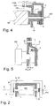
- Fig. 4 shows an example mounting possibility of the holder H directly to another wall GW of the housing.
- the further wall GW is a wall GW, which extends parallel to the axis of rotation of the spindle nut SM.
- the holder H is bent away from the bearing portion and extends parallel to the further wall GW.
- this has a longitudinal slot HS, through which the threaded shank of a screw HSR is guided to screw the screw HSR in a threaded bore GB of the further wall GW.
- this makes possible an alignment of the holder H in the axial direction X and in particular a biasing with a desired voltage against the arrangement of elastic element E, bearing bushing L and spindle nut SM.
- this holder H is thus a housing directly associated with the holder and not a holder H, which is also designed as a holder for the spindle nut SM and the entire housing to an external component.
- Fig. 5 shows a further exemplary arrangement of the holder H on the wall W of the housing.
- the holder H itself consists of such an elastic material that the holder H presses with its inside wall directly with a chip force F against the bearing bush L in the direction of the spindle nut SM.
- the holder H is correspondingly attached directly to the wall W itself, for example, fastened by means of a screw or soldered connection.
- FIG. 6 shows an alternative embodiment of the bearing bush L.
- This bearing bush L differs from the two-part bearing bush L sketched in FIG. 3 in that between the walls of the end faces S1, S2 in the interior an elastic element E *, in particular in the form of a helical spring , is used.
- This elastic element E * pushes apart the two bearing bush elements L 1, L 2 and thus assumes the function of the elastic element E used at the end side of the bearing bush L in the overall arrangement according to, for example, FIG. 1.
Applications Claiming Priority (1)
| Application Number | Priority Date | Filing Date | Title |
|---|---|---|---|
| DE102004059538A DE102004059538B3 (de) | 2004-12-09 | 2004-12-09 | Spindelmutter-Lageranordnung |
Publications (3)
| Publication Number | Publication Date |
|---|---|
| EP1669618A2 true EP1669618A2 (fr) | 2006-06-14 |
| EP1669618A3 EP1669618A3 (fr) | 2007-12-05 |
| EP1669618B1 EP1669618B1 (fr) | 2008-08-20 |
Family
ID=35511676
Family Applications (1)
| Application Number | Title | Priority Date | Filing Date |
|---|---|---|---|
| EP05019315A Not-in-force EP1669618B1 (fr) | 2004-12-09 | 2005-09-06 | Ensemble palier pour écrou de broche |
Country Status (6)
| Country | Link |
|---|---|
| US (1) | US8113073B2 (fr) |
| EP (1) | EP1669618B1 (fr) |
| CN (1) | CN100526682C (fr) |
| AT (1) | ATE405756T1 (fr) |
| DE (2) | DE102004059538B3 (fr) |
| ES (1) | ES2311913T3 (fr) |
Families Citing this family (3)
| Publication number | Priority date | Publication date | Assignee | Title |
|---|---|---|---|---|
| DE102007023329A1 (de) | 2007-05-16 | 2008-11-20 | Ims Gear Gmbh | Getriebe für eine Verstelleinrichtung, insbesondere eine Kfz-Verstelleinrichtung, mit Spielausgleich |
| FR3071784B1 (fr) * | 2017-09-29 | 2019-10-18 | Faurecia Sieges D'automobile | Mecanisme de reglage a vis, glissiere comportant un tel mecanisme de reglage et siege comportant une telle glissiere. |
| CN107701711A (zh) * | 2017-11-18 | 2018-02-16 | 苏州金牛精密机械有限公司 | 一种齿轮间隙调整机构 |
Citations (4)
| Publication number | Priority date | Publication date | Assignee | Title |
|---|---|---|---|---|
| JPS57171115A (en) * | 1981-04-13 | 1982-10-21 | Niigata Eng Co Ltd | Bearing |
| DE3327946A1 (de) * | 1983-08-03 | 1985-02-21 | Schoppe & Faeser Gmbh, 4950 Minden | Durch einen endlagenfesten elektromotor angetriebener schubantrieb |
| WO2001027482A1 (fr) * | 1999-10-14 | 2001-04-19 | Steyr Daimler Puch Fahrzeugtechnik Ag & Co Kg | Systeme de paliers pour arbre a vitesse de rotation elevee |
| DE10308028A1 (de) * | 2003-02-24 | 2004-09-02 | C. Rob. Hammerstein Gmbh & Co. Kg | Spindelgetriebe für Verstellvorrichtungen in Kraftfahrzeugsitzen |
Family Cites Families (14)
| Publication number | Priority date | Publication date | Assignee | Title |
|---|---|---|---|---|
| US3122936A (en) * | 1964-03-03 | dykes | ||
| US3822024A (en) * | 1972-11-07 | 1974-07-02 | Eastman Kodak Co | Card loading mechanism for a photographic copying machine |
| US4036330A (en) * | 1974-12-18 | 1977-07-19 | The B. F. Goodrich Company | Disc brake |
| US4022300A (en) * | 1976-08-19 | 1977-05-10 | Dayton-Walther Corporation | Mechanical disc brake |
| DE2709592C2 (de) * | 1977-03-03 | 1979-04-26 | Kraftwerk Union Ag, 4330 Muelheim | Vorrichtung zum Drehen und Transportieren der Muttern mehrerer auf einem Lochkreis angeordneter Schraubenbolzen |
| US4406352A (en) * | 1980-12-01 | 1983-09-27 | Rockwell International Corporation | Disc brake actuator |
| US4442725A (en) * | 1981-05-26 | 1984-04-17 | Shigiya Machinery Works, Ltd. | Shock absorbing apparatus for travelling a table or tool rest in machine tools |
| US4498350A (en) * | 1982-09-20 | 1985-02-12 | Eaton Corporation | Shifting mechanism |
| FR2580759B1 (fr) * | 1985-04-18 | 1990-02-23 | Marchal Equip Auto | Dispositif de commande du deplacement d'un element, notamment d'un siege ou des parties d'un siege d'un vehicule automobile, par rapport a un bati |
| US5251986A (en) * | 1992-08-10 | 1993-10-12 | Grumman Aerospace Corporation | Bushing assembly |
| DE4434401C1 (de) * | 1994-09-16 | 1995-11-16 | Mannesmann Ag | Wegaufnehmergetriebe in einem Schubantrieb |
| US20010029797A1 (en) * | 2000-04-27 | 2001-10-18 | Thomson Saginaw Ball Screw Company, L.L.C. | Multiple stage, multiple extend, speed reducing ball screw linear actuator and method of constructing and operating the actuator |
| JP2002046039A (ja) * | 2000-08-01 | 2002-02-12 | Smc Corp | 電動アクチュエーター |
| CN2628808Y (zh) * | 2003-05-19 | 2004-07-28 | 王秋勇 | 可自动限位保护的丝杆副 |
-
2004
- 2004-12-09 DE DE102004059538A patent/DE102004059538B3/de not_active Expired - Fee Related
-
2005
- 2005-09-06 AT AT05019315T patent/ATE405756T1/de not_active IP Right Cessation
- 2005-09-06 DE DE502005005090T patent/DE502005005090D1/de active Active
- 2005-09-06 EP EP05019315A patent/EP1669618B1/fr not_active Not-in-force
- 2005-09-06 ES ES05019315T patent/ES2311913T3/es active Active
- 2005-10-26 CN CN200510114154.4A patent/CN100526682C/zh not_active Expired - Fee Related
- 2005-12-09 US US11/298,921 patent/US8113073B2/en not_active Expired - Fee Related
Patent Citations (4)
| Publication number | Priority date | Publication date | Assignee | Title |
|---|---|---|---|---|
| JPS57171115A (en) * | 1981-04-13 | 1982-10-21 | Niigata Eng Co Ltd | Bearing |
| DE3327946A1 (de) * | 1983-08-03 | 1985-02-21 | Schoppe & Faeser Gmbh, 4950 Minden | Durch einen endlagenfesten elektromotor angetriebener schubantrieb |
| WO2001027482A1 (fr) * | 1999-10-14 | 2001-04-19 | Steyr Daimler Puch Fahrzeugtechnik Ag & Co Kg | Systeme de paliers pour arbre a vitesse de rotation elevee |
| DE10308028A1 (de) * | 2003-02-24 | 2004-09-02 | C. Rob. Hammerstein Gmbh & Co. Kg | Spindelgetriebe für Verstellvorrichtungen in Kraftfahrzeugsitzen |
Also Published As
| Publication number | Publication date |
|---|---|
| EP1669618B1 (fr) | 2008-08-20 |
| DE102004059538B3 (de) | 2006-01-26 |
| DE502005005090D1 (de) | 2008-10-02 |
| US20060123938A1 (en) | 2006-06-15 |
| CN1786520A (zh) | 2006-06-14 |
| CN100526682C (zh) | 2009-08-12 |
| US8113073B2 (en) | 2012-02-14 |
| EP1669618A3 (fr) | 2007-12-05 |
| ES2311913T3 (es) | 2009-02-16 |
| ATE405756T1 (de) | 2008-09-15 |
Similar Documents
| Publication | Publication Date | Title |
|---|---|---|
| EP2951053B1 (fr) | Transmission a broche et un dispositif de réglage d'un véhicule et siège de véhicule | |
| EP0892724B1 (fr) | Dispositif de fixation | |
| EP1679223B1 (fr) | Transmission pour un dispositif de réglage | |
| DE3738924C2 (fr) | ||
| EP2184029A2 (fr) | Vis à allongement pour la régulation de dents | |
| DE202004016321U1 (de) | Zug-Druck-Stange | |
| EP2459425B1 (fr) | Ensemble constitué d'un réservoir de compensation et d'un maître-cylindre pour un système de freinage hydraulique d'un véhicule à moteur | |
| EP2951052A1 (fr) | Transmission à broche destinée à un dispositif de réglage d'un véhicule à moteur et d'un siège de véhicule | |
| EP0918671B1 (fr) | Unite d'entrainement electrique | |
| EP1010595B1 (fr) | Pédale d'un véhicule | |
| DE102018100458B4 (de) | Getriebegehäuseeinheit und Getriebeeinheit mit keilförmigem Ausgleichselement zum Axialspielausgleich | |
| WO2006048285A1 (fr) | Systeme de fixation notamment destine a un echangeur thermique | |
| EP1669618B1 (fr) | Ensemble palier pour écrou de broche | |
| EP2605939B1 (fr) | Dispositif d'essuie-glace | |
| EP1676761B1 (fr) | Dispositif d'essuie-glace | |
| WO2007012551A1 (fr) | Dispositif d'essuie-glace, en particulier pour vehicule automobile | |
| DE19735753A1 (de) | Drehstabanordnung | |
| DE19939255A1 (de) | Fahrzeugsitzvorrichtung | |
| DE102018131864A1 (de) | Lagereinheit für eine Schneckenwelle eines Lenkgetriebes | |
| DE19906693C1 (de) | Stellantrieb, insbesondere für Heizungs-, Lüftungs-, oder Klimaklappen im Kfz | |
| DE102019005341A1 (de) | Positionierungseinrichtung zur Anordnung eines ersten Bauteils relativ zu einem weiteren Bauteil eines Kraftwagens | |
| DE102012107857B4 (de) | Lagerbuchse | |
| EP2424083B1 (fr) | Moteur électrique et son procédé de fabrication | |
| EP2067652A2 (fr) | Elément d'adaptateur et mécanisme de réglage doté d'un élément d'adaptateur | |
| DE102020001422A1 (de) | Einstelleinheit zur Einstellung einer Ausrichtung eines an einem Fahrzeugchassis befestigten Fahrwerkbauteils |
Legal Events
| Date | Code | Title | Description |
|---|---|---|---|
| PUAI | Public reference made under article 153(3) epc to a published international application that has entered the european phase |
Free format text: ORIGINAL CODE: 0009012 |
|
| AK | Designated contracting states |
Kind code of ref document: A2 Designated state(s): AT BE BG CH CY CZ DE DK EE ES FI FR GB GR HU IE IS IT LI LT LU LV MC NL PL PT RO SE SI SK TR |
|
| AX | Request for extension of the european patent |
Extension state: AL BA HR MK YU |
|
| PUAL | Search report despatched |
Free format text: ORIGINAL CODE: 0009013 |
|
| AK | Designated contracting states |
Kind code of ref document: A3 Designated state(s): AT BE BG CH CY CZ DE DK EE ES FI FR GB GR HU IE IS IT LI LT LU LV MC NL PL PT RO SE SI SK TR |
|
| AX | Request for extension of the european patent |
Extension state: AL BA HR MK YU |
|
| RIC1 | Information provided on ipc code assigned before grant |
Ipc: F16H 57/02 20060101ALI20071026BHEP Ipc: B60N 2/06 20060101ALI20071026BHEP Ipc: F16C 25/04 20060101AFI20060324BHEP Ipc: F16H 25/20 20060101ALI20071026BHEP |
|
| 17P | Request for examination filed |
Effective date: 20080115 |
|
| GRAP | Despatch of communication of intention to grant a patent |
Free format text: ORIGINAL CODE: EPIDOSNIGR1 |
|
| GRAS | Grant fee paid |
Free format text: ORIGINAL CODE: EPIDOSNIGR3 |
|
| GRAA | (expected) grant |
Free format text: ORIGINAL CODE: 0009210 |
|
| AKX | Designation fees paid |
Designated state(s): AT BE BG CH CY CZ DE DK EE ES FI FR GB GR HU IE IS IT LI LT LU LV MC NL PL PT RO SE SI SK TR |
|
| AK | Designated contracting states |
Kind code of ref document: B1 Designated state(s): AT BE BG CH CY CZ DE DK EE ES FI FR GB GR HU IE IS IT LI LT LU LV MC NL PL PT RO SE SI SK TR |
|
| REG | Reference to a national code |
Ref country code: GB Ref legal event code: FG4D Free format text: NOT ENGLISH |
|
| REG | Reference to a national code |
Ref country code: CH Ref legal event code: EP |
|
| REG | Reference to a national code |
Ref country code: IE Ref legal event code: FG4D Free format text: LANGUAGE OF EP DOCUMENT: GERMAN |
|
| REF | Corresponds to: |
Ref document number: 502005005090 Country of ref document: DE Date of ref document: 20081002 Kind code of ref document: P |
|
| PG25 | Lapsed in a contracting state [announced via postgrant information from national office to epo] |
Ref country code: IS Free format text: LAPSE BECAUSE OF FAILURE TO SUBMIT A TRANSLATION OF THE DESCRIPTION OR TO PAY THE FEE WITHIN THE PRESCRIBED TIME-LIMIT Effective date: 20081220 Ref country code: NL Free format text: LAPSE BECAUSE OF FAILURE TO SUBMIT A TRANSLATION OF THE DESCRIPTION OR TO PAY THE FEE WITHIN THE PRESCRIBED TIME-LIMIT Effective date: 20080820 Ref country code: LT Free format text: LAPSE BECAUSE OF FAILURE TO SUBMIT A TRANSLATION OF THE DESCRIPTION OR TO PAY THE FEE WITHIN THE PRESCRIBED TIME-LIMIT Effective date: 20080820 |
|
| REG | Reference to a national code |
Ref country code: ES Ref legal event code: FG2A Ref document number: 2311913 Country of ref document: ES Kind code of ref document: T3 |
|
| PG25 | Lapsed in a contracting state [announced via postgrant information from national office to epo] |
Ref country code: LV Free format text: LAPSE BECAUSE OF FAILURE TO SUBMIT A TRANSLATION OF THE DESCRIPTION OR TO PAY THE FEE WITHIN THE PRESCRIBED TIME-LIMIT Effective date: 20080820 Ref country code: FI Free format text: LAPSE BECAUSE OF FAILURE TO SUBMIT A TRANSLATION OF THE DESCRIPTION OR TO PAY THE FEE WITHIN THE PRESCRIBED TIME-LIMIT Effective date: 20080820 Ref country code: SI Free format text: LAPSE BECAUSE OF FAILURE TO SUBMIT A TRANSLATION OF THE DESCRIPTION OR TO PAY THE FEE WITHIN THE PRESCRIBED TIME-LIMIT Effective date: 20080820 |
|
| BERE | Be: lapsed |
Owner name: IMS GEAR G.M.B.H. Effective date: 20080930 |
|
| REG | Reference to a national code |
Ref country code: IE Ref legal event code: FD4D |
|
| PG25 | Lapsed in a contracting state [announced via postgrant information from national office to epo] |
Ref country code: BG Free format text: LAPSE BECAUSE OF FAILURE TO SUBMIT A TRANSLATION OF THE DESCRIPTION OR TO PAY THE FEE WITHIN THE PRESCRIBED TIME-LIMIT Effective date: 20081120 Ref country code: IE Free format text: LAPSE BECAUSE OF FAILURE TO SUBMIT A TRANSLATION OF THE DESCRIPTION OR TO PAY THE FEE WITHIN THE PRESCRIBED TIME-LIMIT Effective date: 20080820 Ref country code: DK Free format text: LAPSE BECAUSE OF FAILURE TO SUBMIT A TRANSLATION OF THE DESCRIPTION OR TO PAY THE FEE WITHIN THE PRESCRIBED TIME-LIMIT Effective date: 20080820 Ref country code: MC Free format text: LAPSE BECAUSE OF NON-PAYMENT OF DUE FEES Effective date: 20080930 |
|
| PG25 | Lapsed in a contracting state [announced via postgrant information from national office to epo] |
Ref country code: SK Free format text: LAPSE BECAUSE OF FAILURE TO SUBMIT A TRANSLATION OF THE DESCRIPTION OR TO PAY THE FEE WITHIN THE PRESCRIBED TIME-LIMIT Effective date: 20080820 Ref country code: CZ Free format text: LAPSE BECAUSE OF FAILURE TO SUBMIT A TRANSLATION OF THE DESCRIPTION OR TO PAY THE FEE WITHIN THE PRESCRIBED TIME-LIMIT Effective date: 20080820 Ref country code: RO Free format text: LAPSE BECAUSE OF FAILURE TO SUBMIT A TRANSLATION OF THE DESCRIPTION OR TO PAY THE FEE WITHIN THE PRESCRIBED TIME-LIMIT Effective date: 20080820 |
|
| PLBE | No opposition filed within time limit |
Free format text: ORIGINAL CODE: 0009261 |
|
| STAA | Information on the status of an ep patent application or granted ep patent |
Free format text: STATUS: NO OPPOSITION FILED WITHIN TIME LIMIT |
|
| 26N | No opposition filed |
Effective date: 20090525 |
|
| PG25 | Lapsed in a contracting state [announced via postgrant information from national office to epo] |
Ref country code: BE Free format text: LAPSE BECAUSE OF NON-PAYMENT OF DUE FEES Effective date: 20080930 Ref country code: EE Free format text: LAPSE BECAUSE OF FAILURE TO SUBMIT A TRANSLATION OF THE DESCRIPTION OR TO PAY THE FEE WITHIN THE PRESCRIBED TIME-LIMIT Effective date: 20080820 |
|
| PG25 | Lapsed in a contracting state [announced via postgrant information from national office to epo] |
Ref country code: AT Free format text: LAPSE BECAUSE OF NON-PAYMENT OF DUE FEES Effective date: 20080906 |
|
| PG25 | Lapsed in a contracting state [announced via postgrant information from national office to epo] |
Ref country code: SE Free format text: LAPSE BECAUSE OF FAILURE TO SUBMIT A TRANSLATION OF THE DESCRIPTION OR TO PAY THE FEE WITHIN THE PRESCRIBED TIME-LIMIT Effective date: 20081120 |
|
| REG | Reference to a national code |
Ref country code: CH Ref legal event code: PL |
|
| GBPC | Gb: european patent ceased through non-payment of renewal fee |
Effective date: 20090906 |
|
| PG25 | Lapsed in a contracting state [announced via postgrant information from national office to epo] |
Ref country code: PL Free format text: LAPSE BECAUSE OF FAILURE TO SUBMIT A TRANSLATION OF THE DESCRIPTION OR TO PAY THE FEE WITHIN THE PRESCRIBED TIME-LIMIT Effective date: 20080820 |
|
| PG25 | Lapsed in a contracting state [announced via postgrant information from national office to epo] |
Ref country code: HU Free format text: LAPSE BECAUSE OF FAILURE TO SUBMIT A TRANSLATION OF THE DESCRIPTION OR TO PAY THE FEE WITHIN THE PRESCRIBED TIME-LIMIT Effective date: 20090221 Ref country code: LU Free format text: LAPSE BECAUSE OF NON-PAYMENT OF DUE FEES Effective date: 20080906 Ref country code: CY Free format text: LAPSE BECAUSE OF FAILURE TO SUBMIT A TRANSLATION OF THE DESCRIPTION OR TO PAY THE FEE WITHIN THE PRESCRIBED TIME-LIMIT Effective date: 20080820 |
|
| PG25 | Lapsed in a contracting state [announced via postgrant information from national office to epo] |
Ref country code: TR Free format text: LAPSE BECAUSE OF FAILURE TO SUBMIT A TRANSLATION OF THE DESCRIPTION OR TO PAY THE FEE WITHIN THE PRESCRIBED TIME-LIMIT Effective date: 20080820 |
|
| PG25 | Lapsed in a contracting state [announced via postgrant information from national office to epo] |
Ref country code: GR Free format text: LAPSE BECAUSE OF FAILURE TO SUBMIT A TRANSLATION OF THE DESCRIPTION OR TO PAY THE FEE WITHIN THE PRESCRIBED TIME-LIMIT Effective date: 20081121 Ref country code: LI Free format text: LAPSE BECAUSE OF NON-PAYMENT OF DUE FEES Effective date: 20090930 Ref country code: CH Free format text: LAPSE BECAUSE OF NON-PAYMENT OF DUE FEES Effective date: 20090930 |
|
| PG25 | Lapsed in a contracting state [announced via postgrant information from national office to epo] |
Ref country code: GB Free format text: LAPSE BECAUSE OF NON-PAYMENT OF DUE FEES Effective date: 20090906 |
|
| PGFP | Annual fee paid to national office [announced via postgrant information from national office to epo] |
Ref country code: IT Payment date: 20100924 Year of fee payment: 6 |
|
| PGFP | Annual fee paid to national office [announced via postgrant information from national office to epo] |
Ref country code: DE Payment date: 20101027 Year of fee payment: 6 |
|
| PG25 | Lapsed in a contracting state [announced via postgrant information from national office to epo] |
Ref country code: PT Free format text: LAPSE BECAUSE OF FAILURE TO SUBMIT A TRANSLATION OF THE DESCRIPTION OR TO PAY THE FEE WITHIN THE PRESCRIBED TIME-LIMIT Effective date: 20080820 |
|
| PGFP | Annual fee paid to national office [announced via postgrant information from national office to epo] |
Ref country code: FR Payment date: 20111005 Year of fee payment: 7 Ref country code: ES Payment date: 20110923 Year of fee payment: 7 |
|
| REG | Reference to a national code |
Ref country code: FR Ref legal event code: ST Effective date: 20130531 |
|
| PG25 | Lapsed in a contracting state [announced via postgrant information from national office to epo] |
Ref country code: DE Free format text: LAPSE BECAUSE OF NON-PAYMENT OF DUE FEES Effective date: 20130403 |
|
| PG25 | Lapsed in a contracting state [announced via postgrant information from national office to epo] |
Ref country code: FR Free format text: LAPSE BECAUSE OF NON-PAYMENT OF DUE FEES Effective date: 20121001 Ref country code: IT Free format text: LAPSE BECAUSE OF NON-PAYMENT OF DUE FEES Effective date: 20120906 |
|
| REG | Reference to a national code |
Ref country code: DE Ref legal event code: R119 Ref document number: 502005005090 Country of ref document: DE Effective date: 20130403 |
|
| REG | Reference to a national code |
Ref country code: ES Ref legal event code: FD2A Effective date: 20131018 |
|
| PG25 | Lapsed in a contracting state [announced via postgrant information from national office to epo] |
Ref country code: ES Free format text: LAPSE BECAUSE OF NON-PAYMENT OF DUE FEES Effective date: 20120907 |