EP1669596A2 - Dispositif de ventilation pour le moyeu de rotor d'une éolienne - Google Patents
Dispositif de ventilation pour le moyeu de rotor d'une éolienne Download PDFInfo
- Publication number
- EP1669596A2 EP1669596A2 EP05023831A EP05023831A EP1669596A2 EP 1669596 A2 EP1669596 A2 EP 1669596A2 EP 05023831 A EP05023831 A EP 05023831A EP 05023831 A EP05023831 A EP 05023831A EP 1669596 A2 EP1669596 A2 EP 1669596A2
- Authority
- EP
- European Patent Office
- Prior art keywords
- nozzle
- plant according
- wind energy
- cup
- energy plant
- Prior art date
- Legal status (The legal status is an assumption and is not a legal conclusion. Google has not performed a legal analysis and makes no representation as to the accuracy of the status listed.)
- Granted
Links
- 238000009423 ventilation Methods 0.000 claims description 13
- XLYOFNOQVPJJNP-UHFFFAOYSA-N water Substances O XLYOFNOQVPJJNP-UHFFFAOYSA-N 0.000 claims description 4
- 230000002093 peripheral effect Effects 0.000 claims 1
- 230000000694 effects Effects 0.000 description 3
- 230000007613 environmental effect Effects 0.000 description 2
- 239000007788 liquid Substances 0.000 description 2
- 239000002245 particle Substances 0.000 description 2
- 238000005452 bending Methods 0.000 description 1
- 238000001816 cooling Methods 0.000 description 1
- 230000001419 dependent effect Effects 0.000 description 1
- 239000000428 dust Substances 0.000 description 1
- 238000004146 energy storage Methods 0.000 description 1
- 239000000463 material Substances 0.000 description 1
- 230000001105 regulatory effect Effects 0.000 description 1
- 230000007704 transition Effects 0.000 description 1
Images

Classifications
-
- F—MECHANICAL ENGINEERING; LIGHTING; HEATING; WEAPONS; BLASTING
- F03—MACHINES OR ENGINES FOR LIQUIDS; WIND, SPRING, OR WEIGHT MOTORS; PRODUCING MECHANICAL POWER OR A REACTIVE PROPULSIVE THRUST, NOT OTHERWISE PROVIDED FOR
- F03D—WIND MOTORS
- F03D1/00—Wind motors with rotation axis substantially parallel to the air flow entering the rotor
- F03D1/06—Rotors
- F03D1/065—Rotors characterised by their construction elements
- F03D1/0691—Rotors characterised by their construction elements of the hub
-
- F—MECHANICAL ENGINEERING; LIGHTING; HEATING; WEAPONS; BLASTING
- F03—MACHINES OR ENGINES FOR LIQUIDS; WIND, SPRING, OR WEIGHT MOTORS; PRODUCING MECHANICAL POWER OR A REACTIVE PROPULSIVE THRUST, NOT OTHERWISE PROVIDED FOR
- F03D—WIND MOTORS
- F03D80/00—Details, components or accessories not provided for in groups F03D1/00 - F03D17/00
- F03D80/60—Cooling or heating of wind motors
-
- F—MECHANICAL ENGINEERING; LIGHTING; HEATING; WEAPONS; BLASTING
- F05—INDEXING SCHEMES RELATING TO ENGINES OR PUMPS IN VARIOUS SUBCLASSES OF CLASSES F01-F04
- F05B—INDEXING SCHEME RELATING TO WIND, SPRING, WEIGHT, INERTIA OR LIKE MOTORS, TO MACHINES OR ENGINES FOR LIQUIDS COVERED BY SUBCLASSES F03B, F03D AND F03G
- F05B2260/00—Function
- F05B2260/60—Fluid transfer
- F05B2260/602—Drainage
-
- F—MECHANICAL ENGINEERING; LIGHTING; HEATING; WEAPONS; BLASTING
- F05—INDEXING SCHEMES RELATING TO ENGINES OR PUMPS IN VARIOUS SUBCLASSES OF CLASSES F01-F04
- F05B—INDEXING SCHEME RELATING TO WIND, SPRING, WEIGHT, INERTIA OR LIKE MOTORS, TO MACHINES OR ENGINES FOR LIQUIDS COVERED BY SUBCLASSES F03B, F03D AND F03G
- F05B2260/00—Function
- F05B2260/60—Fluid transfer
- F05B2260/64—Aeration, ventilation, dehumidification or moisture removal of closed spaces
-
- Y—GENERAL TAGGING OF NEW TECHNOLOGICAL DEVELOPMENTS; GENERAL TAGGING OF CROSS-SECTIONAL TECHNOLOGIES SPANNING OVER SEVERAL SECTIONS OF THE IPC; TECHNICAL SUBJECTS COVERED BY FORMER USPC CROSS-REFERENCE ART COLLECTIONS [XRACs] AND DIGESTS
- Y02—TECHNOLOGIES OR APPLICATIONS FOR MITIGATION OR ADAPTATION AGAINST CLIMATE CHANGE
- Y02E—REDUCTION OF GREENHOUSE GAS [GHG] EMISSIONS, RELATED TO ENERGY GENERATION, TRANSMISSION OR DISTRIBUTION
- Y02E10/00—Energy generation through renewable energy sources
- Y02E10/70—Wind energy
- Y02E10/72—Wind turbines with rotation axis in wind direction
Definitions
- the present invention relates to a device for ventilating a Rotomabe a wind turbine.
- the power absorbed by the rotor from the wind is limited by the setting angle (pitch angle) of the rotor blades and is often regulated in their value.
- the equipment required for changing the pitch angle ie in particular servo motors, control, energy storage, etc., are often located in the hub. These devices, as well as other components in the hub, must be protected as much as possible from negative environmental influences.
- the invention has for its object to provide a ventilation device of a Rotomabe in a wind turbine, on the one hand a ensures adequate ventilation and on the other hand prevents the ingress of water, dust and the like.
- the object of the invention is achieved by a wind energy plant with a ventilation device of the rotor hub, wherein the ventilation has a cup-shaped element and a tubular neck.
- the cup-shaped element has a bottom and a circumferential side wall.
- the tubular nozzle leads into an interior of the rotor hub.
- the cup-shaped element is held in front of an inlet opening of the nozzle in such a way that the inlet opening is shielded laterally by the side wall. This ensures that the incoming air flow must pass past the side wall of the cup-shaped element in the interior and from here, reversing its direction of movement enters the interior of the Rotomabe.
- the nozzle is arranged substantially on the axis of rotation of the hub. This ensures on the one hand that the air flow entering through the pipe is directed directly onto the hub. On the other hand, this positioning also ensures that a dynamic pressure forming in front of the rotor hub directs the inflowing air into the rotor hub via the cup-shaped element, into it and from there via the connecting piece with sufficient pressure. Also allows the Ventilation device according to the invention a pressure equalization in the wing during the tower passage in the rotation of the rotor blades. As a result, the pump effect occurring in the wings can be compensated and the stress on the wing material can be further reduced.
- the cross section of the inlet opening in the nozzle increases, for this purpose, the wall of the nozzle is inclined outwards.
- the wall of the nozzle rotates about its longitudinal axis. Entering liquid or particles are moved by the centrifugal force of the inlet opening at an outwardly inclined wall.
- the cup-shaped element has an inner diameter which is greater than the outer diameter of the nozzle. If the cup-shaped element and the neck are rotationally symmetrical, they can be arranged with their axis of symmetry on the axis of rotation of the rotor hub, so that they also rotate about the rotation axis during operation of the wind turbine.
- a wall element which has a recess with a central opening, on which the nozzle is placed or through which the nozzle extends.
- the nozzle can be placed only on the opening of the wall element or pass through the wall element, to guide the air flow deeper into the Rotomabe.
- the wall element outside of the recess is flat.
- the base of the cup-shaped element is preferably in a height with the wall element.
- the cup-shaped element held in the recess of the wall element forms with its base in this embodiment essentially a plane with the wall element.
- the wall element is articulated via at least one arm to a frame pivotally.
- the arm preferably forms a hatch, which can be closed by the pivotable wall element.
- fastening means are preferably provided on the frame and / or on the wall element in order to close the central hatch.
- the edge of the wall element is bent along a circumferential bending line.
- the edge of the wall element is arranged at a distance from a jacket of the rotor hub, so that an outlet channel for the air is formed from the interior of the rotor hub.
- the nozzle extends beyond the wall element into the interior of the rotor hub in order to convey the air into the interior of the rotor hub.
- an elastic hose can be attached to the end of the nozzle, passes through the air deeper into the interior of the rotor hub.
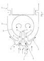
- FIG. 1 shows a schematic view of a rotor hub 101, which is surrounded by a sheathing 102.
- the sheath is referred to below as a spinner.
- Rotomabe 101 and spinner 102 rotate relative to the nacelle 103.
- the ventilation of the hub takes place from the front, that is, from the direction from which the air flows.
- the vent has a cup-shaped closure 104, which is arranged in front of an inlet opening in the nozzle 108.
- the nozzle 108 protrudes through a bottom element 105 into the interior of the rotor hub.
- the air flow swirls and then emerges again, as indicated by the flow arrow 114, through a further air channel 107 between wall element 105 and spinner 102, cf. Air flow 115.
- This effect is assisted by the air flowing past the hub, which develops a suction effect in the region of the outlet opening for the air flow 115 and increases the air throughput.
- the air channels 106 and 107 are preferably formed so that they can be easily opened or pushed aside to allow access from the interior of the spinner 102 into an interior of the Rotomabe 101.
- Fig. 1 it can be seen that the cross-sectional area increases towards the inlet opening. As a result, the air is facilitated in the interior. In addition, any moisture that has entered is forwarded by the centrifugal force from the inlet opening, as well as by the slope 109 of the bottom element. It can also be seen in FIG. 1 that the wall 116 of the attachment 104 is inclined inwards, so that a wider entrance into the air channel is present for the air flow 112.
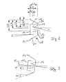
- Fig. 2 shows the geometric structure of the ventilation system.
- the cup-shaped element has a circular shape.
- the side wall 12 is inclined inwards by about 5 °.
- the cup-shaped element 10 is arranged in front of an inlet opening 14 of a nozzle 16.
- the nozzle wall 16 is open at an angle of about 15 ° relative to the central axis to the outside, so that in total the nozzle 16 has the shape of a truncated cone.
- the nozzle 16 is arranged in a wall element 18 which has a bottom element 20 in a depression.
- the nozzle 16 is centrally located on the bottom 20 of the recess.
- Adjacent to the base side walls 22 are provided, which are also inclined relative to the horizontal.
- the side walls 22 go into a region 24, which is shown in Fig. 2 only in approach.
- the distance between the free edge 26 of the nozzle 16 and transition from wall element to side wall 22 then results exactly as twice the width of the side wall 22.
- the nozzle 16 has an opening angle in the example of about 15 °, the nozzle 16 in the diameter of 1.0 reduced to 0.5. Also in the axial direction have certain Conditions proved to be particularly advantageous.
- the extent of the recess in the axial direction is 1.5, wherein the cover 10 is immersed approximately at half the depth.
- the nozzle 16 protrudes by approximately one unit of length so that there is an overlap of the side wall 12 and the nozzle 16 in the axial direction of 0.25.
- Fig. 3 shows the inclination, also referred to as tilt, with respect to the horizontal.
- the nozzle 16 and the cover 10 are inclined by the same angle ⁇ .
- the angle ⁇ is usually between 3 ° and 7 °, preferably a tilt angle of 5 ° is selected.
- the limitation of the opening is even with a tilt so dimensioned that water is rejected and can run off.
- the inclination of the nozzle 16 is indicated in Fig. 3 with the angle ⁇ , while the inclination of the side wall 22 has been marked with the angle ⁇ . To ensure a run, the following applies: ⁇ > ⁇ and ⁇ > ⁇
- Fig. 4 shows a perspective view of the ventilation system according to the invention, which is integrated in an access hatch for the rotor hub.
- the access hatch is located in the tip of the Rotomabe, or their housing.
- the access hatch has a wall plate 28, with a central opening 30 and fasteners 32 along the circumference.
- L-shaped locking projections 34 are mounted with a slot-shaped recess 36.
- a hatch 39 is hinged to a frame 40 pivotally.
- the hatch 39 opens inwards.
- the hatch frame 40 can be secured in the recesses 36.
- a handle 50 is provided in the region of the fastening pins 42.
- Fig. 5 shows the hatch cover 39 from the inside, with a square frame 54 of the air inlet is clearly visible. On the frame 54, a filter 52 can be set, which additionally prevents the entry of dirt and water.
- FIG. 6 shows a cross section in which it can be clearly seen that the side walls 56 of the attached cup element 46 project beyond the inlet opening 58 of the socket 60.
Applications Claiming Priority (1)
| Application Number | Priority Date | Filing Date | Title |
|---|---|---|---|
| DE102004058776A DE102004058776B3 (de) | 2004-12-07 | 2004-12-07 | Vorrichtung zur Belüftung einer Rotornabe einer Windenergieanlage |
Publications (3)
| Publication Number | Publication Date |
|---|---|
| EP1669596A2 true EP1669596A2 (fr) | 2006-06-14 |
| EP1669596A3 EP1669596A3 (fr) | 2008-09-03 |
| EP1669596B1 EP1669596B1 (fr) | 2010-01-13 |
Family
ID=35355873
Family Applications (1)
| Application Number | Title | Priority Date | Filing Date |
|---|---|---|---|
| EP05023831A Not-in-force EP1669596B1 (fr) | 2004-12-07 | 2005-11-02 | Dispositif de ventilation pour le moyeu de rotor d'une éolienne |
Country Status (6)
| Country | Link |
|---|---|
| US (1) | US7513736B2 (fr) |
| EP (1) | EP1669596B1 (fr) |
| AT (1) | ATE455245T1 (fr) |
| DE (2) | DE102004058776B3 (fr) |
| ES (1) | ES2335594T3 (fr) |
| NO (1) | NO331131B1 (fr) |
Cited By (6)
| Publication number | Priority date | Publication date | Assignee | Title |
|---|---|---|---|---|
| EP1884659A2 (fr) * | 2006-07-31 | 2008-02-06 | General Electric Company | Dispositif de ventilation pour le moyeu de rotor d'une éolienne |
| WO2008098574A1 (fr) * | 2007-02-12 | 2008-08-21 | Vestas Wind Systems A/S | Eolienne, procédé pour créer au moins une ouverture dans le nez de rotor sur le moyeu d'un rotor d'éolienne et utilisation d'une éolienne |
| WO2010022724A3 (fr) * | 2008-08-28 | 2010-09-10 | Vestas Wind Systems A/S | Filtrage de débris dans des éoliennes |
| CN101943139A (zh) * | 2010-09-27 | 2011-01-12 | 中国计量学院 | 用于风力发电机组的自适应型防风沙装置 |
| WO2011012683A3 (fr) * | 2009-07-29 | 2011-10-20 | Suzlon Energy Gmbh | Boîtier pour une turbine éolienne |
| CN106286155A (zh) * | 2016-08-29 | 2017-01-04 | 优利康达(天津)科技有限公司 | 一种电机导流罩 |
Families Citing this family (18)
| Publication number | Priority date | Publication date | Assignee | Title |
|---|---|---|---|---|
| DE102006055091A1 (de) * | 2006-11-21 | 2008-05-29 | Repower Systems Ag | Schott einer Windenergieanlage |
| US20090035148A1 (en) * | 2007-08-02 | 2009-02-05 | General Electric Company | Wind Turbine Blade Drainage |
| US8186940B2 (en) | 2007-09-05 | 2012-05-29 | General Electric Company | Ventilation arrangement |
| DE102007043503B4 (de) * | 2007-09-12 | 2015-12-24 | Ssb Wind Systems Gmbh & Co. Kg | Schaltschrank für eine Windkraftanlage |
| JP4898621B2 (ja) * | 2007-10-05 | 2012-03-21 | 三菱重工業株式会社 | 風力発電装置 |
| DE102007052276B3 (de) | 2007-10-31 | 2009-01-15 | Nordex Energy Gmbh | Vorrichtung zur Belüftung einer Rotornabe einer Windenergieanlage |
| DE102009019453B3 (de) * | 2008-05-13 | 2010-09-30 | Suzlon Energy Gmbh | Schaltschrank für eine Windturbine |
| CN102084129A (zh) * | 2008-06-24 | 2011-06-01 | 维斯塔斯风力系统有限公司 | 用于风轮机轮毂的轮毂封闭件 |
| JP5148517B2 (ja) * | 2009-01-07 | 2013-02-20 | 三菱重工業株式会社 | 風力発電装置 |
| KR20110050705A (ko) * | 2009-02-27 | 2011-05-16 | 미츠비시 쥬고교 가부시키가이샤 | 풍력 발전 장치 |
| JP5001999B2 (ja) * | 2009-12-16 | 2012-08-15 | 三菱重工業株式会社 | 風力発電装置 |
| CA2738004A1 (fr) * | 2011-01-28 | 2012-07-28 | Mitsubishi Heavy Industries, Ltd. | Generateur eolien |
| ITTO20110140U1 (it) * | 2011-12-15 | 2013-06-16 | Gate Srl | Gruppo di ventilazione per uno scambiatore di calore, particolarmente per un autoveicolo |
| KR101325687B1 (ko) * | 2012-03-08 | 2013-11-05 | 삼성중공업 주식회사 | 빗물 유입 방지 구조 및 이를 구비한 풍력 발전기 |
| EP2724022B1 (fr) * | 2012-07-31 | 2015-04-08 | Mitsubishi Heavy Industries, Ltd. | Éolienne avec système de ventilation |
| US9657719B2 (en) | 2014-06-16 | 2017-05-23 | General Electric Company | Ventilation arrangement |
| CN105863953B (zh) * | 2016-03-24 | 2019-01-11 | 北京金风科创风电设备有限公司 | 风力发电机叶片、风力发电机散热装置及风力发电机组 |
| CN106438228B (zh) * | 2016-10-08 | 2018-12-07 | 北京金风科创风电设备有限公司 | 风力发电机组的机舱散热机构及散热方法 |
Citations (3)
| Publication number | Priority date | Publication date | Assignee | Title |
|---|---|---|---|---|
| JPS5865977A (ja) * | 1981-10-14 | 1983-04-19 | Hitachi Ltd | 風力発電装置の冷却機構 |
| EP1375913A1 (fr) * | 2002-06-28 | 2004-01-02 | High Technology Investments B.V. | Eolienne avec générateur à disque |
| US20040160063A1 (en) * | 1999-05-12 | 2004-08-19 | Marcel Le Nabour | Wind machine with slanted blades |
Family Cites Families (3)
| Publication number | Priority date | Publication date | Assignee | Title |
|---|---|---|---|---|
| AU573349B2 (en) * | 1984-06-26 | 1988-06-02 | F F Seeley Nominees Pty Ltd | Fan motor/rotor arrangement |
| FR2621554B1 (fr) * | 1987-10-07 | 1990-01-05 | Snecma | Capot d'entree non tournant de turboreacteur a fixation centrale et turboreacteur ainsi equipe |
| FR2760492B1 (fr) * | 1997-03-10 | 2001-11-09 | Jeumont Ind | Systeme de production d'energie electrique associe a une eolienne |
-
2004
- 2004-12-07 DE DE102004058776A patent/DE102004058776B3/de not_active Expired - Fee Related
-
2005
- 2005-11-02 AT AT05023831T patent/ATE455245T1/de not_active IP Right Cessation
- 2005-11-02 ES ES05023831T patent/ES2335594T3/es active Active
- 2005-11-02 DE DE502005008861T patent/DE502005008861D1/de active Active
- 2005-11-02 EP EP05023831A patent/EP1669596B1/fr not_active Not-in-force
- 2005-11-18 US US11/282,555 patent/US7513736B2/en not_active Expired - Fee Related
- 2005-12-06 NO NO20055788A patent/NO331131B1/no not_active IP Right Cessation
Patent Citations (3)
| Publication number | Priority date | Publication date | Assignee | Title |
|---|---|---|---|---|
| JPS5865977A (ja) * | 1981-10-14 | 1983-04-19 | Hitachi Ltd | 風力発電装置の冷却機構 |
| US20040160063A1 (en) * | 1999-05-12 | 2004-08-19 | Marcel Le Nabour | Wind machine with slanted blades |
| EP1375913A1 (fr) * | 2002-06-28 | 2004-01-02 | High Technology Investments B.V. | Eolienne avec générateur à disque |
Cited By (11)
| Publication number | Priority date | Publication date | Assignee | Title |
|---|---|---|---|---|
| EP1884659A2 (fr) * | 2006-07-31 | 2008-02-06 | General Electric Company | Dispositif de ventilation pour le moyeu de rotor d'une éolienne |
| EP1884659A3 (fr) * | 2006-07-31 | 2012-11-07 | General Electric Company | Dispositif de ventilation pour le moyeu de rotor d'une éolienne |
| CN101117942B (zh) * | 2006-07-31 | 2013-02-13 | 通用电气公司 | 用于风力涡轮机转子毂的通风装置 |
| WO2008098574A1 (fr) * | 2007-02-12 | 2008-08-21 | Vestas Wind Systems A/S | Eolienne, procédé pour créer au moins une ouverture dans le nez de rotor sur le moyeu d'un rotor d'éolienne et utilisation d'une éolienne |
| US8021121B2 (en) | 2007-02-12 | 2011-09-20 | Vestas Wind Systems A/S | Wind turbine, a method for establishing at least one aperture in the spinner of the hub of a wind turbine rotor and use of a wind turbine |
| CN101652564B (zh) * | 2007-02-12 | 2012-07-11 | 维斯塔斯风力系统有限公司 | 风轮机、在风轮机转子的轮毂上的轮毂罩中建立至少一个孔口的方法及风轮机的使用 |
| WO2010022724A3 (fr) * | 2008-08-28 | 2010-09-10 | Vestas Wind Systems A/S | Filtrage de débris dans des éoliennes |
| US8961110B2 (en) | 2008-08-28 | 2015-02-24 | Vestas Wind Systems A/S | Filtering of debris in wind turbines |
| WO2011012683A3 (fr) * | 2009-07-29 | 2011-10-20 | Suzlon Energy Gmbh | Boîtier pour une turbine éolienne |
| CN101943139A (zh) * | 2010-09-27 | 2011-01-12 | 中国计量学院 | 用于风力发电机组的自适应型防风沙装置 |
| CN106286155A (zh) * | 2016-08-29 | 2017-01-04 | 优利康达(天津)科技有限公司 | 一种电机导流罩 |
Also Published As
| Publication number | Publication date |
|---|---|
| DE502005008861D1 (de) | 2010-03-04 |
| NO20055788L (no) | 2006-06-08 |
| DE102004058776B3 (de) | 2006-07-13 |
| EP1669596B1 (fr) | 2010-01-13 |
| US20060120862A1 (en) | 2006-06-08 |
| NO331131B1 (no) | 2011-10-17 |
| US7513736B2 (en) | 2009-04-07 |
| EP1669596A3 (fr) | 2008-09-03 |
| NO20055788D0 (no) | 2005-12-06 |
| ES2335594T3 (es) | 2010-03-30 |
| ATE455245T1 (de) | 2010-01-15 |
Similar Documents
| Publication | Publication Date | Title |
|---|---|---|
| EP1669596B1 (fr) | Dispositif de ventilation pour le moyeu de rotor d'une éolienne | |
| DE810500C (de) | Windturbine | |
| DE3419964C2 (de) | Spritzkopf eines Hochdruckreinigungsgerätes | |
| DE112009000712B4 (de) | Haubenleitschaufeln eines Motorkühllüfters mit offenen Flügeln | |
| DE2103035B2 (de) | Lufteinlaß für Gasturbinentriebwerke | |
| DE102012007405A1 (de) | Arbeitsgerät | |
| DE102015000732A1 (de) | Blasgerät | |
| EP2055941B1 (fr) | Dispositif de ventilation pour le moyeu de rotor d'une éolienne | |
| EP3348804B1 (fr) | Réservoir de lubrifiant pour un système hydraulique | |
| CH637031A5 (en) | Aeration arrangement at a device immersed in a liquid | |
| EP0045736A1 (fr) | Dispositif pour séparer les poussières d'un courant d'air | |
| AT503184B1 (de) | Unterschlächtiges wasserrad | |
| DE2847672C2 (de) | Rotor zur Umwandlung von Windkraft in elektrische und mechanische Energie | |
| DE102011108512B4 (de) | Windkraftanlage | |
| DE102010009793A1 (de) | Windkraftanlage | |
| EP2927476A1 (fr) | Rotor et turbine à entraînement fluidique dotée de rotor | |
| DE102007058274A1 (de) | Mantelstromwindkonverter und Verfahren zum Betrieb desselben | |
| DE112017004377T5 (de) | Windturbinenanlage | |
| DE202012011189U1 (de) | Vorrichtung zur Energieerzeugung | |
| DE102019220089A1 (de) | Düsenelement für einen Strahlventilator und Strahlventilator | |
| EP3425117B1 (fr) | Dispositif de génération d'un écoulement rotationnel pour un dispositif de franchissement piscicole | |
| DE10052209B4 (de) | Staubsaugerfilter | |
| AT510208B1 (de) | Windkraftanlage | |
| DE102016112876A1 (de) | Durchströmwindkraftanlage | |
| EP3001028A1 (fr) | Cône pour un moyeu de rotor |
Legal Events
| Date | Code | Title | Description |
|---|---|---|---|
| PUAI | Public reference made under article 153(3) epc to a published international application that has entered the european phase |
Free format text: ORIGINAL CODE: 0009012 |
|
| AK | Designated contracting states |
Kind code of ref document: A2 Designated state(s): AT BE BG CH CY CZ DE DK EE ES FI FR GB GR HU IE IS IT LI LT LU LV MC NL PL PT RO SE SI SK TR |
|
| AX | Request for extension of the european patent |
Extension state: AL BA HR MK YU |
|
| PUAL | Search report despatched |
Free format text: ORIGINAL CODE: 0009013 |
|
| AK | Designated contracting states |
Kind code of ref document: A3 Designated state(s): AT BE BG CH CY CZ DE DK EE ES FI FR GB GR HU IE IS IT LI LT LU LV MC NL PL PT RO SE SI SK TR |
|
| AX | Request for extension of the european patent |
Extension state: AL BA HR MK YU |
|
| RIC1 | Information provided on ipc code assigned before grant |
Ipc: F03D 11/00 20060101ALI20080729BHEP Ipc: F03D 1/06 20060101AFI20051201BHEP |
|
| 17P | Request for examination filed |
Effective date: 20090221 |
|
| AKX | Designation fees paid |
Designated state(s): AT BE BG CH CY CZ DE DK EE ES FI FR GB GR HU IE IS IT LI LT LU LV MC NL PL PT RO SE SI SK TR |
|
| GRAP | Despatch of communication of intention to grant a patent |
Free format text: ORIGINAL CODE: EPIDOSNIGR1 |
|
| GRAS | Grant fee paid |
Free format text: ORIGINAL CODE: EPIDOSNIGR3 |
|
| GRAA | (expected) grant |
Free format text: ORIGINAL CODE: 0009210 |
|
| AK | Designated contracting states |
Kind code of ref document: B1 Designated state(s): AT BE BG CH CY CZ DE DK EE ES FI FR GB GR HU IE IS IT LI LT LU LV MC NL PL PT RO SE SI SK TR |
|
| REG | Reference to a national code |
Ref country code: GB Ref legal event code: FG4D Free format text: NOT ENGLISH |
|
| REG | Reference to a national code |
Ref country code: CH Ref legal event code: EP |
|
| REG | Reference to a national code |
Ref country code: IE Ref legal event code: FG4D |
|
| REF | Corresponds to: |
Ref document number: 502005008861 Country of ref document: DE Date of ref document: 20100304 Kind code of ref document: P |
|
| REG | Reference to a national code |
Ref country code: ES Ref legal event code: FG2A Ref document number: 2335594 Country of ref document: ES Kind code of ref document: T3 |
|
| REG | Reference to a national code |
Ref country code: NL Ref legal event code: VDEP Effective date: 20100113 |
|
| LTIE | Lt: invalidation of european patent or patent extension |
Effective date: 20100113 |
|
| PG25 | Lapsed in a contracting state [announced via postgrant information from national office to epo] |
Ref country code: LT Free format text: LAPSE BECAUSE OF FAILURE TO SUBMIT A TRANSLATION OF THE DESCRIPTION OR TO PAY THE FEE WITHIN THE PRESCRIBED TIME-LIMIT Effective date: 20100113 Ref country code: IS Free format text: LAPSE BECAUSE OF FAILURE TO SUBMIT A TRANSLATION OF THE DESCRIPTION OR TO PAY THE FEE WITHIN THE PRESCRIBED TIME-LIMIT Effective date: 20100513 Ref country code: NL Free format text: LAPSE BECAUSE OF FAILURE TO SUBMIT A TRANSLATION OF THE DESCRIPTION OR TO PAY THE FEE WITHIN THE PRESCRIBED TIME-LIMIT Effective date: 20100113 |
|
| PG25 | Lapsed in a contracting state [announced via postgrant information from national office to epo] |
Ref country code: LV Free format text: LAPSE BECAUSE OF FAILURE TO SUBMIT A TRANSLATION OF THE DESCRIPTION OR TO PAY THE FEE WITHIN THE PRESCRIBED TIME-LIMIT Effective date: 20100113 Ref country code: PL Free format text: LAPSE BECAUSE OF FAILURE TO SUBMIT A TRANSLATION OF THE DESCRIPTION OR TO PAY THE FEE WITHIN THE PRESCRIBED TIME-LIMIT Effective date: 20100113 Ref country code: SI Free format text: LAPSE BECAUSE OF FAILURE TO SUBMIT A TRANSLATION OF THE DESCRIPTION OR TO PAY THE FEE WITHIN THE PRESCRIBED TIME-LIMIT Effective date: 20100113 Ref country code: FI Free format text: LAPSE BECAUSE OF FAILURE TO SUBMIT A TRANSLATION OF THE DESCRIPTION OR TO PAY THE FEE WITHIN THE PRESCRIBED TIME-LIMIT Effective date: 20100113 |
|
| PG25 | Lapsed in a contracting state [announced via postgrant information from national office to epo] |
Ref country code: GR Free format text: LAPSE BECAUSE OF FAILURE TO SUBMIT A TRANSLATION OF THE DESCRIPTION OR TO PAY THE FEE WITHIN THE PRESCRIBED TIME-LIMIT Effective date: 20100414 Ref country code: SE Free format text: LAPSE BECAUSE OF FAILURE TO SUBMIT A TRANSLATION OF THE DESCRIPTION OR TO PAY THE FEE WITHIN THE PRESCRIBED TIME-LIMIT Effective date: 20100113 Ref country code: CY Free format text: LAPSE BECAUSE OF FAILURE TO SUBMIT A TRANSLATION OF THE DESCRIPTION OR TO PAY THE FEE WITHIN THE PRESCRIBED TIME-LIMIT Effective date: 20100113 Ref country code: EE Free format text: LAPSE BECAUSE OF FAILURE TO SUBMIT A TRANSLATION OF THE DESCRIPTION OR TO PAY THE FEE WITHIN THE PRESCRIBED TIME-LIMIT Effective date: 20100113 Ref country code: RO Free format text: LAPSE BECAUSE OF FAILURE TO SUBMIT A TRANSLATION OF THE DESCRIPTION OR TO PAY THE FEE WITHIN THE PRESCRIBED TIME-LIMIT Effective date: 20100113 |
|
| PLBE | No opposition filed within time limit |
Free format text: ORIGINAL CODE: 0009261 |
|
| STAA | Information on the status of an ep patent application or granted ep patent |
Free format text: STATUS: NO OPPOSITION FILED WITHIN TIME LIMIT |
|
| PG25 | Lapsed in a contracting state [announced via postgrant information from national office to epo] |
Ref country code: BG Free format text: LAPSE BECAUSE OF FAILURE TO SUBMIT A TRANSLATION OF THE DESCRIPTION OR TO PAY THE FEE WITHIN THE PRESCRIBED TIME-LIMIT Effective date: 20100413 Ref country code: SK Free format text: LAPSE BECAUSE OF FAILURE TO SUBMIT A TRANSLATION OF THE DESCRIPTION OR TO PAY THE FEE WITHIN THE PRESCRIBED TIME-LIMIT Effective date: 20100113 Ref country code: CZ Free format text: LAPSE BECAUSE OF FAILURE TO SUBMIT A TRANSLATION OF THE DESCRIPTION OR TO PAY THE FEE WITHIN THE PRESCRIBED TIME-LIMIT Effective date: 20100113 |
|
| 26N | No opposition filed |
Effective date: 20101014 |
|
| PG25 | Lapsed in a contracting state [announced via postgrant information from national office to epo] |
Ref country code: DK Free format text: LAPSE BECAUSE OF FAILURE TO SUBMIT A TRANSLATION OF THE DESCRIPTION OR TO PAY THE FEE WITHIN THE PRESCRIBED TIME-LIMIT Effective date: 20100113 |
|
| PG25 | Lapsed in a contracting state [announced via postgrant information from national office to epo] |
Ref country code: IT Free format text: LAPSE BECAUSE OF FAILURE TO SUBMIT A TRANSLATION OF THE DESCRIPTION OR TO PAY THE FEE WITHIN THE PRESCRIBED TIME-LIMIT Effective date: 20100113 |
|
| BERE | Be: lapsed |
Owner name: NORDEX ENERGY G.M.B.H. Effective date: 20101130 |
|
| PG25 | Lapsed in a contracting state [announced via postgrant information from national office to epo] |
Ref country code: MC Free format text: LAPSE BECAUSE OF NON-PAYMENT OF DUE FEES Effective date: 20101130 |
|
| REG | Reference to a national code |
Ref country code: CH Ref legal event code: PL |
|
| PG25 | Lapsed in a contracting state [announced via postgrant information from national office to epo] |
Ref country code: CH Free format text: LAPSE BECAUSE OF NON-PAYMENT OF DUE FEES Effective date: 20101130 Ref country code: LI Free format text: LAPSE BECAUSE OF NON-PAYMENT OF DUE FEES Effective date: 20101130 |
|
| PG25 | Lapsed in a contracting state [announced via postgrant information from national office to epo] |
Ref country code: BE Free format text: LAPSE BECAUSE OF NON-PAYMENT OF DUE FEES Effective date: 20101130 |
|
| PGFP | Annual fee paid to national office [announced via postgrant information from national office to epo] |
Ref country code: IE Payment date: 20111121 Year of fee payment: 7 |
|
| REG | Reference to a national code |
Ref country code: AT Ref legal event code: MM01 Ref document number: 455245 Country of ref document: AT Kind code of ref document: T Effective date: 20101102 |
|
| PG25 | Lapsed in a contracting state [announced via postgrant information from national office to epo] |
Ref country code: AT Free format text: LAPSE BECAUSE OF NON-PAYMENT OF DUE FEES Effective date: 20101102 |
|
| PG25 | Lapsed in a contracting state [announced via postgrant information from national office to epo] |
Ref country code: HU Free format text: LAPSE BECAUSE OF FAILURE TO SUBMIT A TRANSLATION OF THE DESCRIPTION OR TO PAY THE FEE WITHIN THE PRESCRIBED TIME-LIMIT Effective date: 20100714 Ref country code: LU Free format text: LAPSE BECAUSE OF NON-PAYMENT OF DUE FEES Effective date: 20101102 |
|
| PG25 | Lapsed in a contracting state [announced via postgrant information from national office to epo] |
Ref country code: TR Free format text: LAPSE BECAUSE OF FAILURE TO SUBMIT A TRANSLATION OF THE DESCRIPTION OR TO PAY THE FEE WITHIN THE PRESCRIBED TIME-LIMIT Effective date: 20100113 |
|
| PGFP | Annual fee paid to national office [announced via postgrant information from national office to epo] |
Ref country code: ES Payment date: 20121122 Year of fee payment: 8 Ref country code: GB Payment date: 20121122 Year of fee payment: 8 |
|
| PGFP | Annual fee paid to national office [announced via postgrant information from national office to epo] |
Ref country code: FR Payment date: 20121217 Year of fee payment: 8 |
|
| PG25 | Lapsed in a contracting state [announced via postgrant information from national office to epo] |
Ref country code: PT Free format text: LAPSE BECAUSE OF NON-PAYMENT OF DUE FEES Effective date: 20100113 |
|
| REG | Reference to a national code |
Ref country code: IE Ref legal event code: MM4A |
|
| PG25 | Lapsed in a contracting state [announced via postgrant information from national office to epo] |
Ref country code: IE Free format text: LAPSE BECAUSE OF NON-PAYMENT OF DUE FEES Effective date: 20121102 |
|
| PGFP | Annual fee paid to national office [announced via postgrant information from national office to epo] |
Ref country code: DE Payment date: 20140113 Year of fee payment: 9 |
|
| GBPC | Gb: european patent ceased through non-payment of renewal fee |
Effective date: 20131102 |
|
| REG | Reference to a national code |
Ref country code: FR Ref legal event code: ST Effective date: 20140731 |
|
| PG25 | Lapsed in a contracting state [announced via postgrant information from national office to epo] |
Ref country code: GB Free format text: LAPSE BECAUSE OF NON-PAYMENT OF DUE FEES Effective date: 20131102 Ref country code: FR Free format text: LAPSE BECAUSE OF NON-PAYMENT OF DUE FEES Effective date: 20131202 |
|
| REG | Reference to a national code |
Ref country code: DE Ref legal event code: R119 Ref document number: 502005008861 Country of ref document: DE |
|
| REG | Reference to a national code |
Ref country code: ES Ref legal event code: FD2A Effective date: 20150709 |
|
| PG25 | Lapsed in a contracting state [announced via postgrant information from national office to epo] |
Ref country code: ES Free format text: LAPSE BECAUSE OF NON-PAYMENT OF DUE FEES Effective date: 20131103 |
|
| PG25 | Lapsed in a contracting state [announced via postgrant information from national office to epo] |
Ref country code: DE Free format text: LAPSE BECAUSE OF NON-PAYMENT OF DUE FEES Effective date: 20150602 |