EP1668614B1 - Verfahren und system zur bereitstellung von warnungen bezüglich einer bevorstehenden fahrzeugkollision - Google Patents
Verfahren und system zur bereitstellung von warnungen bezüglich einer bevorstehenden fahrzeugkollision Download PDFInfo
- Publication number
- EP1668614B1 EP1668614B1 EP04770524A EP04770524A EP1668614B1 EP 1668614 B1 EP1668614 B1 EP 1668614B1 EP 04770524 A EP04770524 A EP 04770524A EP 04770524 A EP04770524 A EP 04770524A EP 1668614 B1 EP1668614 B1 EP 1668614B1
- Authority
- EP
- European Patent Office
- Prior art keywords
- driven vehicle
- velocity
- collision
- vehicle
- driver
- Prior art date
- Legal status (The legal status is an assumption and is not a legal conclusion. Google has not performed a legal analysis and makes no representation as to the accuracy of the status listed.)
- Expired - Lifetime
Links
- 238000000034 method Methods 0.000 title claims abstract description 36
- 239000013598 vector Substances 0.000 claims abstract description 107
- 230000033001 locomotion Effects 0.000 claims abstract description 15
- 238000005070 sampling Methods 0.000 claims abstract description 14
- 230000000116 mitigating effect Effects 0.000 claims description 20
- 238000001514 detection method Methods 0.000 claims description 6
- 230000035515 penetration Effects 0.000 claims description 5
- 239000002131 composite material Substances 0.000 claims description 4
- 238000012545 processing Methods 0.000 claims description 3
- 230000003213 activating effect Effects 0.000 claims description 2
- 230000005540 biological transmission Effects 0.000 claims description 2
- 230000000977 initiatory effect Effects 0.000 claims 1
- 230000001965 increasing effect Effects 0.000 abstract description 3
- 230000003247 decreasing effect Effects 0.000 abstract description 2
- 230000008859 change Effects 0.000 description 25
- 238000013459 approach Methods 0.000 description 5
- 230000007704 transition Effects 0.000 description 5
- 230000001133 acceleration Effects 0.000 description 3
- 230000004044 response Effects 0.000 description 3
- 230000000007 visual effect Effects 0.000 description 3
- 230000009471 action Effects 0.000 description 2
- 230000004397 blinking Effects 0.000 description 2
- 230000001939 inductive effect Effects 0.000 description 2
- 238000013507 mapping Methods 0.000 description 2
- 230000035484 reaction time Effects 0.000 description 2
- 238000000926 separation method Methods 0.000 description 2
- 230000006978 adaptation Effects 0.000 description 1
- 230000034303 cell budding Effects 0.000 description 1
- 238000004891 communication Methods 0.000 description 1
- 230000001419 dependent effect Effects 0.000 description 1
- 230000000881 depressing effect Effects 0.000 description 1
- 238000013461 design Methods 0.000 description 1
- 238000006073 displacement reaction Methods 0.000 description 1
- 230000002349 favourable effect Effects 0.000 description 1
- 238000005259 measurement Methods 0.000 description 1
- 238000012986 modification Methods 0.000 description 1
- 230000004048 modification Effects 0.000 description 1
- 230000000149 penetrating effect Effects 0.000 description 1
- 238000002360 preparation method Methods 0.000 description 1
- 238000011160 research Methods 0.000 description 1
Images


Classifications
-
- B—PERFORMING OPERATIONS; TRANSPORTING
- B60—VEHICLES IN GENERAL
- B60R—VEHICLES, VEHICLE FITTINGS, OR VEHICLE PARTS, NOT OTHERWISE PROVIDED FOR
- B60R21/00—Arrangements or fittings on vehicles for protecting or preventing injuries to occupants or pedestrians in case of accidents or other traffic risks
- B60R21/01—Electrical circuits for triggering passive safety arrangements, e.g. airbags, safety belt tighteners, in case of vehicle accidents or impending vehicle accidents
- B60R21/013—Electrical circuits for triggering passive safety arrangements, e.g. airbags, safety belt tighteners, in case of vehicle accidents or impending vehicle accidents including means for detecting collisions, impending collisions or roll-over
-
- B—PERFORMING OPERATIONS; TRANSPORTING
- B62—LAND VEHICLES FOR TRAVELLING OTHERWISE THAN ON RAILS
- B62D—MOTOR VEHICLES; TRAILERS
- B62D15/00—Steering not otherwise provided for
- B62D15/02—Steering position indicators ; Steering position determination; Steering aids
- B62D15/025—Active steering aids, e.g. helping the driver by actively influencing the steering system after environment evaluation
- B62D15/0265—Automatic obstacle avoidance by steering
-
- B—PERFORMING OPERATIONS; TRANSPORTING
- B62—LAND VEHICLES FOR TRAVELLING OTHERWISE THAN ON RAILS
- B62D—MOTOR VEHICLES; TRAILERS
- B62D15/00—Steering not otherwise provided for
- B62D15/02—Steering position indicators ; Steering position determination; Steering aids
- B62D15/029—Steering assistants using warnings or proposing actions to the driver without influencing the steering system
-
- G—PHYSICS
- G01—MEASURING; TESTING
- G01S—RADIO DIRECTION-FINDING; RADIO NAVIGATION; DETERMINING DISTANCE OR VELOCITY BY USE OF RADIO WAVES; LOCATING OR PRESENCE-DETECTING BY USE OF THE REFLECTION OR RERADIATION OF RADIO WAVES; ANALOGOUS ARRANGEMENTS USING OTHER WAVES
- G01S13/00—Systems using the reflection or reradiation of radio waves, e.g. radar systems; Analogous systems using reflection or reradiation of waves whose nature or wavelength is irrelevant or unspecified
- G01S13/88—Radar or analogous systems specially adapted for specific applications
- G01S13/93—Radar or analogous systems specially adapted for specific applications for anti-collision purposes
- G01S13/931—Radar or analogous systems specially adapted for specific applications for anti-collision purposes of land vehicles
-
- G—PHYSICS
- G08—SIGNALLING
- G08G—TRAFFIC CONTROL SYSTEMS
- G08G1/00—Traffic control systems for road vehicles
- G08G1/16—Anti-collision systems
- G08G1/164—Centralised systems, e.g. external to vehicles
-
- G—PHYSICS
- G08—SIGNALLING
- G08G—TRAFFIC CONTROL SYSTEMS
- G08G1/00—Traffic control systems for road vehicles
- G08G1/16—Anti-collision systems
- G08G1/166—Anti-collision systems for active traffic, e.g. moving vehicles, pedestrians, bikes
-
- G—PHYSICS
- G08—SIGNALLING
- G08G—TRAFFIC CONTROL SYSTEMS
- G08G1/00—Traffic control systems for road vehicles
- G08G1/16—Anti-collision systems
- G08G1/167—Driving aids for lane monitoring, lane changing, e.g. blind spot detection
-
- B—PERFORMING OPERATIONS; TRANSPORTING
- B60—VEHICLES IN GENERAL
- B60R—VEHICLES, VEHICLE FITTINGS, OR VEHICLE PARTS, NOT OTHERWISE PROVIDED FOR
- B60R21/00—Arrangements or fittings on vehicles for protecting or preventing injuries to occupants or pedestrians in case of accidents or other traffic risks
- B60R21/01—Electrical circuits for triggering passive safety arrangements, e.g. airbags, safety belt tighteners, in case of vehicle accidents or impending vehicle accidents
- B60R21/013—Electrical circuits for triggering passive safety arrangements, e.g. airbags, safety belt tighteners, in case of vehicle accidents or impending vehicle accidents including means for detecting collisions, impending collisions or roll-over
- B60R21/0134—Electrical circuits for triggering passive safety arrangements, e.g. airbags, safety belt tighteners, in case of vehicle accidents or impending vehicle accidents including means for detecting collisions, impending collisions or roll-over responsive to imminent contact with an obstacle, e.g. using radar systems
-
- B—PERFORMING OPERATIONS; TRANSPORTING
- B60—VEHICLES IN GENERAL
- B60W—CONJOINT CONTROL OF VEHICLE SUB-UNITS OF DIFFERENT TYPE OR DIFFERENT FUNCTION; CONTROL SYSTEMS SPECIALLY ADAPTED FOR HYBRID VEHICLES; ROAD VEHICLE DRIVE CONTROL SYSTEMS FOR PURPOSES NOT RELATED TO THE CONTROL OF A PARTICULAR SUB-UNIT
- B60W50/00—Details of control systems for road vehicle drive control not related to the control of a particular sub-unit, e.g. process diagnostic or vehicle driver interfaces
- B60W50/08—Interaction between the driver and the control system
- B60W50/14—Means for informing the driver, warning the driver or prompting a driver intervention
- B60W2050/146—Display means
-
- B—PERFORMING OPERATIONS; TRANSPORTING
- B60—VEHICLES IN GENERAL
- B60W—CONJOINT CONTROL OF VEHICLE SUB-UNITS OF DIFFERENT TYPE OR DIFFERENT FUNCTION; CONTROL SYSTEMS SPECIALLY ADAPTED FOR HYBRID VEHICLES; ROAD VEHICLE DRIVE CONTROL SYSTEMS FOR PURPOSES NOT RELATED TO THE CONTROL OF A PARTICULAR SUB-UNIT
- B60W2554/00—Input parameters relating to objects
- B60W2554/40—Dynamic objects, e.g. animals, windblown objects
- B60W2554/404—Characteristics
- B60W2554/4041—Position
-
- B—PERFORMING OPERATIONS; TRANSPORTING
- B60—VEHICLES IN GENERAL
- B60W—CONJOINT CONTROL OF VEHICLE SUB-UNITS OF DIFFERENT TYPE OR DIFFERENT FUNCTION; CONTROL SYSTEMS SPECIALLY ADAPTED FOR HYBRID VEHICLES; ROAD VEHICLE DRIVE CONTROL SYSTEMS FOR PURPOSES NOT RELATED TO THE CONTROL OF A PARTICULAR SUB-UNIT
- B60W2554/00—Input parameters relating to objects
- B60W2554/80—Spatial relation or speed relative to objects
-
- B—PERFORMING OPERATIONS; TRANSPORTING
- B60—VEHICLES IN GENERAL
- B60W—CONJOINT CONTROL OF VEHICLE SUB-UNITS OF DIFFERENT TYPE OR DIFFERENT FUNCTION; CONTROL SYSTEMS SPECIALLY ADAPTED FOR HYBRID VEHICLES; ROAD VEHICLE DRIVE CONTROL SYSTEMS FOR PURPOSES NOT RELATED TO THE CONTROL OF A PARTICULAR SUB-UNIT
- B60W30/00—Purposes of road vehicle drive control systems not related to the control of a particular sub-unit, e.g. of systems using conjoint control of vehicle sub-units
- B60W30/08—Active safety systems predicting or avoiding probable or impending collision or attempting to minimise its consequences
- B60W30/09—Taking automatic action to avoid collision, e.g. braking and steering
-
- B—PERFORMING OPERATIONS; TRANSPORTING
- B60—VEHICLES IN GENERAL
- B60W—CONJOINT CONTROL OF VEHICLE SUB-UNITS OF DIFFERENT TYPE OR DIFFERENT FUNCTION; CONTROL SYSTEMS SPECIALLY ADAPTED FOR HYBRID VEHICLES; ROAD VEHICLE DRIVE CONTROL SYSTEMS FOR PURPOSES NOT RELATED TO THE CONTROL OF A PARTICULAR SUB-UNIT
- B60W30/00—Purposes of road vehicle drive control systems not related to the control of a particular sub-unit, e.g. of systems using conjoint control of vehicle sub-units
- B60W30/14—Adaptive cruise control
- B60W30/16—Control of distance between vehicles, e.g. keeping a distance to preceding vehicle
-
- G—PHYSICS
- G01—MEASURING; TESTING
- G01S—RADIO DIRECTION-FINDING; RADIO NAVIGATION; DETERMINING DISTANCE OR VELOCITY BY USE OF RADIO WAVES; LOCATING OR PRESENCE-DETECTING BY USE OF THE REFLECTION OR RERADIATION OF RADIO WAVES; ANALOGOUS ARRANGEMENTS USING OTHER WAVES
- G01S13/00—Systems using the reflection or reradiation of radio waves, e.g. radar systems; Analogous systems using reflection or reradiation of waves whose nature or wavelength is irrelevant or unspecified
- G01S13/88—Radar or analogous systems specially adapted for specific applications
- G01S13/93—Radar or analogous systems specially adapted for specific applications for anti-collision purposes
- G01S13/931—Radar or analogous systems specially adapted for specific applications for anti-collision purposes of land vehicles
- G01S2013/932—Radar or analogous systems specially adapted for specific applications for anti-collision purposes of land vehicles using own vehicle data, e.g. ground speed, steering wheel direction
-
- G—PHYSICS
- G01—MEASURING; TESTING
- G01S—RADIO DIRECTION-FINDING; RADIO NAVIGATION; DETERMINING DISTANCE OR VELOCITY BY USE OF RADIO WAVES; LOCATING OR PRESENCE-DETECTING BY USE OF THE REFLECTION OR RERADIATION OF RADIO WAVES; ANALOGOUS ARRANGEMENTS USING OTHER WAVES
- G01S13/00—Systems using the reflection or reradiation of radio waves, e.g. radar systems; Analogous systems using reflection or reradiation of waves whose nature or wavelength is irrelevant or unspecified
- G01S13/88—Radar or analogous systems specially adapted for specific applications
- G01S13/93—Radar or analogous systems specially adapted for specific applications for anti-collision purposes
- G01S13/931—Radar or analogous systems specially adapted for specific applications for anti-collision purposes of land vehicles
- G01S2013/9321—Velocity regulation, e.g. cruise control
-
- G—PHYSICS
- G01—MEASURING; TESTING
- G01S—RADIO DIRECTION-FINDING; RADIO NAVIGATION; DETERMINING DISTANCE OR VELOCITY BY USE OF RADIO WAVES; LOCATING OR PRESENCE-DETECTING BY USE OF THE REFLECTION OR RERADIATION OF RADIO WAVES; ANALOGOUS ARRANGEMENTS USING OTHER WAVES
- G01S13/00—Systems using the reflection or reradiation of radio waves, e.g. radar systems; Analogous systems using reflection or reradiation of waves whose nature or wavelength is irrelevant or unspecified
- G01S13/88—Radar or analogous systems specially adapted for specific applications
- G01S13/93—Radar or analogous systems specially adapted for specific applications for anti-collision purposes
- G01S13/931—Radar or analogous systems specially adapted for specific applications for anti-collision purposes of land vehicles
- G01S2013/9322—Radar or analogous systems specially adapted for specific applications for anti-collision purposes of land vehicles using additional data, e.g. driver condition, road state or weather data
-
- G—PHYSICS
- G01—MEASURING; TESTING
- G01S—RADIO DIRECTION-FINDING; RADIO NAVIGATION; DETERMINING DISTANCE OR VELOCITY BY USE OF RADIO WAVES; LOCATING OR PRESENCE-DETECTING BY USE OF THE REFLECTION OR RERADIATION OF RADIO WAVES; ANALOGOUS ARRANGEMENTS USING OTHER WAVES
- G01S13/00—Systems using the reflection or reradiation of radio waves, e.g. radar systems; Analogous systems using reflection or reradiation of waves whose nature or wavelength is irrelevant or unspecified
- G01S13/88—Radar or analogous systems specially adapted for specific applications
- G01S13/93—Radar or analogous systems specially adapted for specific applications for anti-collision purposes
- G01S13/931—Radar or analogous systems specially adapted for specific applications for anti-collision purposes of land vehicles
- G01S2013/9325—Radar or analogous systems specially adapted for specific applications for anti-collision purposes of land vehicles for inter-vehicle distance regulation, e.g. navigating in platoons
Definitions
- the present invention relates to the field of traffic safety systems. More particularly, the invention relates to a system for warning a driver of a vehicle from impending collisions with other vehicles or objects present in his vicinity.
- Collision avoidance is a basic requirement of all drivers of ground vehicles, such as automobiles, trucks, motorcycles (hereinafter referred to as “vehicles”) while driving to a desired destination.
- vehicle such as automobiles, trucks, motorcycles
- the basic collision avoidance maneuvers of a given vehicle A include a stopping maneuver S in its current lane and a lane change maneuver L by which driven vehicle A safely merges with vehicles B and C in the neighboring lane.
- US 5,34,206 discloses a method for avoiding a collision between a motor vehicle and obstacles in the path of the vehicle by forming a radar map of the area in front of the vehicle, reconstructing the geometry of the road, identifying its edges, detecting the position and speed of the vehicle with respect to the road, determining the presumed path of the vehicle on the basis of the road geometry and the maneuver being carried out by the vehicle at that instant, detecting objects on the radar map found lying in the presumed path of the motor vehicle and displaying the map found in a perspective representation, ignoring objects which are off the road and indicating objects in the path of the vehicle in a different manner according to their hazard and if appropriate, generating alarms of an acoustic type.
- EP 1223093 discloses a braking control system that includes a control unit which is electronically connected to an object detector and a host vehicle speed sensor for automatically controlling, depending on a host vehicle speed and a relative distance, a braking force needed for an automatic braking operation.
- the control unit detects the presence or absence of a driver's intention for lane-changing.
- the control unit inhibits preliminary braking control, initiated prior to the driver's braking action, or reduces the degree of limitation on supplementary braking control, through which a value of a controlled quantity is brought closer to a target deceleration rate needed for collision-avoidance.
- US 5,529,138 discloses an automobile collision avoidance system based on laser radars for aiding in avoidance of automobile collisions.
- the system detects the location, the direction of movement, the speed and the size of all obstacles specifically and precisely.
- a steering wheel rotation sensor or a laser gyroscope is utilized to give information of system-equipped vehicle's directional change.
- the system compares the predicted collision time with the minimal allowable time to determine the imminency of a collision, and when determined, provides a warning.
- An optional automatic braking device is used when the vehicle user fails to respond to a warning.
- a wheel skidding detecting system based on a discrepancy between the directional change rate predicted by a steering wheel rotation sensor and the actual directional change rate detected by a laser gyroscope is also disclosed.
- US 5,870,303 discloses a method for controlling the maneuvers of a robotic vehicle in the presence of obstacles by using a three-dimensional configuration space which propagates cost waves in configuration space and using budding search strategy.
- Obstacle avoidance by automated vehicles that merge with neighboring traffic has been achieved by first producing a gap in a neighboring lane and then executing a lane change maneuver into the produced gap [Godbole et al, "Design of Emergency Maneuvers for Automated Highway System: Obstacle Avoidance Problem," CDC 1997].
- the drawback of such an approach is that the driven vehicle is dependent upon the maneuvers of neighboring vehicles with which the driven car communicates and which may not accurately perform the maneuver requested by the driven vehicle.
- the minimum clearing distance, beyond which an obstacle cannot be avoided at a given initial speed is determined.
- a lane change maneuver is generally the most desirable option since traffic flow is least disturbed, such a maneuver may not be immediately feasible, depending on the distance to the obstacle, speed of the driven vehicle, and the volume of traffic in the neighboring lanes. If a lane change maneuver is not feasible, a full stop is generally the best alternative. However, if the initial speed and distance from the obstacle are insufficient for a full stop, the driven vehicle needs to decelerate until the traffic conditions allow a lane change maneuver to take place. Once the driven vehicle approaches the obstacle within the minimum clearing distance, a collision is unavoidable.
- the minimum clearing distance CD is the longitudinal distance along the X-axis, which represents the initial direction of driven vehicle A, from initial position X o of driven vehicle A until intersection point 10, at which a vertex of driven vehicle A intersects a vertex of the stationary obstacle O as driven vehicle A follows an optimal lane transition maneuver until final position X f .
- An optimal lane transition maneuver is a maneuver that minimizes longitudinal displacement of driven vehicle A without collision while taking into account the initial speed ⁇ o , vehicle dynamics, and road conditions. Similarly, an optimal lane transition maneuver may be carried out for a moving obstacle, as well.
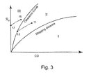
- Fig. 3 graphically illustrates three regimes of vehicular driving conditions in terms of the difficulty in avoiding a collision with a detected obstacle.
- Each regime is representative of various combinations of vehicular speed and minimum clearing distance from the obstacle (hereinafter referred to as "states").
- the clearance curve is representative of the relationship between initial speed ⁇ o and minimum clearance distance CD for an optimal lane transition maneuver, which may be generated while considering the driver's reaction time, as well as the motion of the obstacle.
- the clearance curve delimits the boundary of safe states of a driven vehicle (Region II), which result in avoidance of the obstacle, from states which result in an unavoidable collision (Region III).
- the stopping distance curve delimiting the boundary of various states of a driven vehicle which facilitate deceleration thereof to a full stop without colliding with the obstacle (Region I) is also illustrated.
- Region I When the obstacle is detected in Region I, sufficient time remains for a full stop or a lane change maneuver without changing speed.
- Region II e.g. at point 11
- the driven vehicle may decelerate, e.g. from point 11 to point 13, and then perform an optimal lane transition maneuver, after which the state of the driven vehicle corresponds to the clearance curve.
- Region III e.g.
- the driven vehicle is precluded from performing a lane change maneuver, and is recommended to remain in the current lane and to decelerate at the maximum deceleration.
- the driven vehicle avoids a more dangerous collision and is involved in a head-on collision at a lower speed, e.g. at point 17, at which speed the driven vehicle is generally designed to withstand the resulting impact such as by means of a bumper. If the driven car were to perform a lane change maneuver in Region III, a more dangerous off-center collision or loss of control is liable to result.
- a velocity obstacle is a set of absolute velocity vectors of a driven vehicle that result, at a future time, in a collision with a given moving obstacle.
- FIG. 4 the initial position of a driven vehicle and a moving obstacle are indicated by points A and B, respectively, while circle B represents the obstacle.
- the initial velocity vectors of driven vehicle A and moving obstacle B are generated and are indicated by V A and V B , respectively.
- the relative velocity vector between A and B is indicated by V AB .
- a planar sector (hereinafter referred to as a "collision cone"), which is representative of all possible relative velocity vectors V AB and having an apex coinciding with A, is then generated.
- Collision cone 20 is bounded by lines R and F which originate at A and are tangent to circle B. Therefore any relative velocity vector V AB coinciding with collision cone 20 will result in a collision and any relative velocity vector V AB not coinciding with collision cone 20 will result in collision-free motion, assuming that obstacle B maintains its current shape and speed.
- velocity obstacle (VO) 25 is produced, which is representative of all possible absolute velocity vectors V A having an apex coinciding with A' at the end of vector V B . Since the illustrated V A penetrates VO 25, such an absolute velocity will result in a collision.
- a plurality of velocity obstacles e.g. VO 25 and 26, for a corresponding number of obstacles, e.g. B and B 1 , may be generated, as shown in Fig. 6 .
- Any absolute velocity vector V A that is outside of all of the velocity obstacles, such as the absolute velocity vector V A illustrated in Fig. 6 the end of which coincides with border R' of VO 25 at point 29, will result in collision-free motion, assuming that the obstacles maintain their current shape and speed. Therefore, any velocities of driven vehicle A that that may be represented by a vector that elongates starting at point A and terminates inside the overlapping region between VOs 25 and 26, will result in a collision with obstacle B or B1.
- a VO may be truncated at a predetermined time horizon th. As shown in Fig. 7 , VO 25 is truncated at predetermined th such that truncated portion 28 is made to be non-displayable. As the remaining portion of VO 25 is shown to be not penetrated by absolute velocity vector V A , this velocity of A therefore, no longer presents a reasonable risk of collision with obstacle B, within t h .
- the prior art methods may provide information regarding the likelihood of a collision, the prior art methods are incapable of determining in real time the most preferred maneuver among a plurality of possible collision avoidance maneuvers. Also, the prior art methods determine a single collision avoidance maneuver for given velocity vectors of a driven vehicle and obstacle, respectively. However, the velocity vectors of the driven vehicle and obstacles are frequently varied in an unpredictable fashion such that the single generated collision avoidance maneuver ceases to be a feasible possibility for preventing a collision. Furthermore, the prior art methods are incapable of determining an optimal collision mitigating maneuver once it is apparent that a collision with the driven vehicle is unavoidable.
- the present invention is directed to a method for transmitting a warning signal to a driver of a driven vehicle regarding an impending collision with a moving and/or stationary object in the vicinity of said drives vehicle.
- the method comprise the steps set forth in claim 1.
- the time to collision may be determined when collision is unavoidable.
- the velocity changes may include changes in direction and/or absolute speed of the driven vehicle.
- the ranges of feasible velocity changes that can be reached within a performance time interval are determined according to the performance capability of the driven vehicle.
- the invention is also directed to a method for determining an optimal collision, mitigating maneuver to be executed by a driver, according to claim 5.
- a pre-crash mode may be initiated whereby vehicular safety accessories are activated.
- One or more airbags may be inflated within the interior of the driven vehicle and/or at the exterior of the driven vehicle, e.g., to extend the bumper.
- the velocity obstacle may be an LVO or an NLVO.
- the method of the present invention may be performed by comparing the relative size of a velocity obstacle, a relatively large velocity obstacle indicating that the corresponding detected vehicle is substantially larger and more massive than the driven vehicle and/or by comparing the relative depth of penetration of one velocity vector within the corresponding velocity obstacles.
- the time to collision of the driven vehicle with each of the detected vehicles may also be compared, when a longer time to collision being indicative of a lower magnitude of impact.
- An optimal collision, mitigating maneuver may be determined by-generating a Velocity obstacle, with respect to the position of the driven vehicle, for each detected vehicle at an initial time of detection; generating a velocity frame delimiting the range of velocity vectors attainable by the driven vehicle in a performance time interval subsequent to the initial time; generating a set of velocity obstacles for each detected vehicle at each sampling time interval subsequent to the initial time, until the end of said performance time interval; superimposing said generated velocity frame on each of said sets, whereby to generate a composite representation; determining which of said generated composite representations includes a region of a velocity obstacle having a lowest predicted magnitude of impact; and determining an optimal collision mitigating maneuver by generating a velocity vector directed from the end of said velocity vector of the driven vehicle to said region having a lowest predicted magnitude of impact.
- the invention is also directed to a system for transmitting a warning signal to a driver of a driven vehicle regarding an impending collision with a detected vehicle in the vicinity of said driven vehicle, according to claim 17.
- the system may further comprise at least one safety accessory, e.g., at least one airbag or an extendible bumper, for mitigating the impact of collision between the driven vehicle and a detected vehicle and means for activating said at least one safety accessory following transmission of said warning signal.
- the system may further comprise control components for temporarily controlling the operation of the driven vehicle during a slave mode, upon consent of the driver, means for overriding the slave mode, an indicator for alerting the driver when the driven vehicle is set in a slave mode, or a screen for displaying a clearance curve generated at an instantaneous sampling time interval and delimiting the boundary of safe states of the driven vehicle from states which result in an unavoidable collision, an instantaneous state of the driven vehicle with respect to the clearance curve being displayable by means of said screen.
- the present invention is a method and system for providing warnings for in-lane and lane change impending collisions, and/or for determining the most optimal collision avoidance maneuver, from a plurality of possible collision avoidance maneuvers for a driven vehicle, the paths of which are generated by an on-board vehicular navigational system.
- the most optimal collision avoidance maneuver is generally a maneuver that is associated with the lowest risk of collision. If the navigational system determines that a collision is unavoidable, a warning is displayed which alerts the driver of the imminence of collision and sets an airbag system into a pre-crash mode, to minimize damage to the driven vehicle.
- the navigational system comprises a suitable number and type of sensors, as well known to those skilled in the art, for accurately determining the navigational conditions, including velocity vector, acceleration, distance from the driven vehicle, and trajectory, of vehicles which are within a predetermined distance from the driven vehicle (hereinafter referred to as "detected vehicles"), as well as for determining the motion of the driven vehicle.
- the computational power of the navigational system is sufficiently high to generate velocity obstacles based on the instantaneous motion of both the driven and detected vehicles at a significantly faster rate than the response time of the drivers of the given vehicles.
- FIGs. 8-12 illustrate various principles and assumptions associated with the method of the invention.
- each vehicle is approximated by a basic circle, with the length of diameter D of a basic circle corresponding to the relative size of the vehicle.
- Vehicle A is designated as the vehicle for which a driver initiated collision avoidance maneuver is desired (hereinafter referred to as the "driven vehicle"), i.e. its driver is assisted by a computerized navigational system to carry out a collision avoidance maneuver.
- a detected vehicle which is within the detection range of the sensors in communication with the driven vehicle navigational system, is designated as B. When more than one vehicle is detected, each detected vehicle is designated by a different subscript.
- the center of each basic circle represents the position of the corresponding vehicle, such that the distance between centers 31 and 32 of basic circles A and B, respectively, is proportional to the actual distance between driven vehicle A and detected vehicle B at the time when the latter is detected (hereinafter referred to as the "initial time").
- the navigational system At the initial time, the navigational system generates velocity vectors V A and V B for driven vehicle A and detected vehicle B, respectively, such that the origin of each velocity vector is positioned at the center of the corresponding basic circle.
- the length of each generated velocity vector is representative of its magnitude.
- the designation of a vector such as V A or V ⁇ ⁇ is interchangeable.
- basic circle 35 of detected vehicle B is enlarged by a factor of 2, as a margin of safety, to a circle 36 having a diameter of 2D (hereinafter referred to as an "enlarged circle") with a center at point 32.
- the basic circle of driven vehicle A is compressed to point 31.
- the following description and illustrations of the method of the invention therefore relate to an enlarged circle B and a compressed circle A, the latter being referred to hereinafter as "A" for brevity.
- the enlarged circle has been enlarged by a factor of 2 assuming that both the detected and driven vehicles of approximately similar size.
- the relative size between the detected and driven vehicles is significantly different, other enlargement factors may be implemented. For example, if the driven vehicle is a truck and the detected vehicle is a private car, the enlargement factor may be as large as 5.
- a larger vehicle may be represented by several circles used for representing the smaller cars.
- Compressing circle A provides a point of reference for generating a relative velocity cone.
- Relative velocity cone 30 bounded by lines R and F which originate at A and are tangent to enlarged circle 36 is then generated.
- Relative velocity cone 30 is representative of all possible relative velocity vectors associated with vehicle A that will result in a collision with vehicle B.
- relative velocity vector V A1B is generated from the relative difference between absolute velocity vector V A1 originating from A and absolute velocity vector V B originating from the center of B, which is copied and positioned in such a way that its origin coincides with A, as shown in Fig. 9A .
- relative velocity vector V A1B is directed outwardly from the boundaries of relative cone 30, indicating that driven vehicle A will not collide with detected vehicle when driven at absolute velocity vector V A1 .
- relative velocity vector V A2B generated from the relative difference between absolute velocity vector V A2 and absolute velocity vector V B penetrates the boundaries of relative cone 30, indicating that driven vehicle A will collide with detected vehicle when driven at absolute velocity vector V A2 .
- use of a relative velocity cone advantageously provides a fast, simple and reliable geometric method of determining whether the driven vehicle is liable to be involved in a collision when being driven at the instantaneous velocity vector.
- Fig. 10 illustrates the generation of a linear velocity obstacle (LVO).
- An LVO is representative of all possible absolute velocity vectors generated at the initial time which are associated with, and originate from, detected vehicle A and are liable to cause a collision with detected vehicle B. Since the detected vehicle is assumed to maintain a linear path at a constant velocity, the generated velocity obstacle is independent of time and its borders are straight lines (linear).
- LVO 40 is produced by adding velocity vector V B to each possible relative velocity vector that is included within relative velocity cone 30. While relative velocity vector V A1B does not penetrate relative velocity cone 30, absolute velocity vector V A1 does not penetrate LVO 40. Conversely, while relative velocity vector V A2B penetrates relative velocity cone 30, absolute velocity vector V A2 penetrates LVO 40.
- Fig, 12 illustrates a situation wherein two vehicles B1 and B2 being driven at a velocity vector of V B1 and V B2 , respectively, are in the detection range of driven vehicle A.
- Two LVOs 45 and 46 are generated from velocity vectors V B1 and V B2 , respectively.
- Absolute velocity vector V A is shown to pass through LVO 46, indicating that driven vehicle A will be driven faster than detected vehicle B2 and therefore will not collide therewith.
- the penetration of an LVO by an absolute velocity vector is indicative of the occurrence of a collision only when the magnitude of the vector is such that it ends inside LVO 45.
- the end of absolute velocity vector V A is outside LVO 45 and therefore, will not collide with detected vehicle B1.
- Figs. 13 and 14 illustrate another embodiment of the invention wherein iterations of driver initiated collision avoidance or collision mitigating maneuvers are performed, such that a most optimal collision avoidance maneuver (MOCAM) or most optimal collision mitigating maneuver (MOCMT) is determined for each of a plurality of time intervals (each of which is referred to herein as a "performance time interval").
- MOCAM most optimal collision avoidance maneuver
- MOCMT most optimal collision mitigating maneuver
- a velocity frame is generated which delimits the range of velocity vectors which is attainable by the driven vehicle in a subsequent performance time interval.
- the change in velocity vector which is attainable by the driven vehicle in a performance time interval is a function of the dynamic constraints thereof such as acceleration and deceleration, road conditions, and driver reaction time.
- a suitable performance time interval which defines the size of a corresponding velocity frame, is one that is sufficiently short so that the driven and detected vehicles move insignificantly within the given performance time interval ⁇ T, yet is sufficiently long so as to allow a driver to change the instantaneous velocity vector of the vehicle.
- the driven vehicle is directed, in accordance with the determined MOCAM or MOCMT, to a point included within the velocity frame.
- Velocity frame 105 is generated after the generation of a linear velocity obstacle at the initial time to, which is designated as LVO(t o ).
- LVO(t o ) is based on absolute velocity vector V B (t o ) and the locations of both driven vehicle A and detected vehicle B at to.
- Velocity frame 105 is representative of the range of absolute velocity vectors attainable by driven vehicle A during the initial performance time interval, which is referred to by t o + ⁇ T.
- the shape and size of the velocity frame 105 are approximated by a rectangle, but in reality, it may assume a different shape, depending on e.g., vehicle characteristics (e.g., steering capability as well as kinematic and dynamic parameters.
- the region between the adjacent borders of the velocity frame and the LVO is representative of the range of velocity vectors generated within a performance time interval ⁇ T by which a collision may be avoided.
- the width of velocity frame 105 is greater than that of the LVO in regions C and D, indicating that a velocity vector coinciding with region C or D will result in collision-free motion. Accordingly, the velocity vector of the driven vehicle may be changed from V A1 (t o ) to V A2 (t o + ⁇ T), which penetrates region C, or to V A3 (t o + ⁇ T), which penetrates region D.
- V A2 (t o + ⁇ T) the choice of velocity vector t o V A2 (t o + ⁇ T) is preferable since region C which is penetrated thereby encompasses a greater range of velocity vectors than region D. Many of the velocity vectors encompassed by region C are also more distantly separated from the borders of the LVO than those encompassed by region D. V A2 (t o + ⁇ T) penetrating region C therefore presents a velocity vector having a lower risk of collision due to human error than V A3 (t o + ⁇ T).
- the selection between V A3 and V A1 also determines the way vehicle A will pass in front or behind vehicle B, respectively. Reference to a velocity frame 105 therefore assists a driver in choosing a change in a vehicular velocity vector which is suitable for avoiding a collision.
- Fig. 14 illustrates a situation wherein the generated velocity frame 106 is completely encompassed by the LVO, indicating that the corresponding driven vehicle can attain a smaller change in its absolute velocity vector V A1 (t o ) during a performance time interval ⁇ T than that associated with velocity frame 105 of Fig. 13 - Since velocity frame 106 is completely encompassed by the LVO, selecting a velocity being within this frame may eventually result in a collision. However, V A2 (t o + ⁇ T) is preferable than V A3 (t o + ⁇ T), since region E of velocity frame penetrated thereby is much closer to the border of the LVO and thus improves the chance to find a collision free velocity within the next ⁇ T. Therefore, velocity frame 106 is also indicative of the most optimal collision mitigating maneuver.
- an LVO is repeatedly regenerated during time intervals shorter than the selected performance time interval, to take into account abrupt changes in motion by the driven vehicle and/or the detected vehicles.
- a time interval is herein referred to as a "sampling time interval" and designated as ⁇ t.
- the configuration of an LVO may be considerably altered after one or two sampling time intervals due an abrupt change in motion, such as acceleration or a lane change maneuver, and therefore may more accurately reflect an optimal driver initiated collision avoidance or collision mitigating maneuver.
- a velocity frame generated in the vicinity of the end of velocity vector V A1 (t o ) may be superimposed over a plurality of LVOs, e.g. LVO(t o + ⁇ t), LVO(t o +2 ⁇ t), each of which is generated one after the other, until the conclusion of the selected performance time interval ⁇ T, and may reveal different possible driver initiated collision avoidance or collision mitigating maneuvers.
- the MOCAM or MOCMT are determined based on the plurality of LVOs which are generated during the selected performance time interval.
- another velocity frame is generated which is based on the instantaneous velocity vectors of the driven and detected vehicles.
- a collision free velocity may be selected if a larger performance time interval is selected.
- the velocity frame may extend outwardly from the borders of the instantaneously generated LVO, indicating that regions G and H would result in collision-free motion.
- a collision avoidance maneuver during one sampling time interval may prove to be a collision inducing maneuver during another sampling time interval.
- the navigational system determines the MOCAM or MOCMT based on the ratio between ⁇ T and ⁇ t.
- Non-Linear Velocity Obstacles NLVOs
- an LVO is based on the assumption that each detected vehicle moves in an essentially linear path and has a substantially constant velocity. However, if the path of these obstacles is non-linear, a similar accurate set of warnings may be provided by generating an NLVO.
- Fig. 15 illustrates a situation wherein a detected vehicle B moves along a curved path C(t), which represents the location of the geometrical center thereof as a function of time.
- NLVOs indicate at an initial time to, similar to LVOs, whether a collision is impending, albeit within the time horizon t h .
- it is required to determine a range of linear velocity vectors Va(t o ) generated at the initial time, for which driven vehicle A will collide with detected vehicle B at time t.
- Such a range of collision inducing velocity vectors is represented by NLVO(t).
- detected vehicle B is located at point C(to).
- detected vehicle B is located at C(t).
- the geometrical dimensions of detected vehicle B are represented by enlarged circle B(t), which is the collection of all points P(t) at time t.
- V ⁇ a (t) is a velocity vector of A at time to that would result in a collision at time t with point P ⁇ 1 (t).
- the enlarged circle B(t) is mapped, i.e. compressed, to another circle NLVO(t).
- the mapped circle NLVO(T) is generated within the cone bounded by lines tangent to the enlarged circle B(t) and originating from driven vehicle A(to).
- NLVO(t) constitutes the instantaneous portion of the NLVO.
- This mapping is repeated for different values of t.
- the result is a collection of different overlapping circles having a decreasing radius and distance from A, as the value of t increases.
- NLVO(t) is a curved cone where both the border lines M 1 and M 2 and the central axis of NLVO(t) converge to point A for increasing values of t.
- Border lines M 1 and M 2 are the collection of all points m 1 (t) and m 2 (t) which coincide with the circumference of a mapped circle and can be approximated to be essentially perpendicular to the central axis of NLVO(t)).
- the curved velocity cone NLVO(t) is generally truncated at a time horizon th corresponding to mapped circle NLVO(t h ), which is representative of a collision that is of a negligible risk .
- th is predetermined to be typically several times the response time of a driver and vehicle, so that the driver may respond sufficiently quickly in order to execute a collision avoidance maneuver.
- a NLVO(t) is similarly repeatedly generated during subsequent time intervals for stationary obstacles (e.g., trees, safety fences, stalled vehicles, etc.), as well as for moving obstacles (such as detected vehicles) in the detection range of A.
- a rectangular velocity frame may be generated, as described hereinabove with respect to Figs. 13 and 14 , and superimposed over each NLVO which is generated during the selected performance time interval, in order to determine a MOCAM or MOCMT.
- the border lines of NLVO(t) may be determined by generating a plurality of circles NLVO(t) for different values of t, up to t h , as described hereinabove. However, in order to reduce the computational time, it is also possible to calculate only the values m 1 (t) and m 2 (t). This is shown in Fig. 17 .
- the linear velocity vector of detected vehicle B at point C(t) is the vector V ⁇ B (t).
- V ⁇ B (t) the vector V ⁇ B (t).
- the resulting linear mapping is the two osculation points m' 1 (t) and m' 2 ( t ), which are then translated by V B ( t ) back to the outline of NLVO(t). This way, only the osculation points m 1 ( t ) and m 2 (t) need to be calculated in order to obtain NLVO(t).
- Fig. 18 shows a plurality of generated NLVOs that corresponds to detected vehicles B1-B3 in the vicinity of driven vehicle A.
- the three moving detected vehicles B1-B3 have three corresponding NLVOs, NLVO1(t)- NLVO3(t), respectively. From the location of A, two possible velocities are drawn, V ⁇ 3 and V ⁇ 4 .
- V ⁇ 3 penetrates NLVO3 (t) at point P3 and V ⁇ ⁇ 4 penetrates NLVO3(t) at point P4. Each penetration point is on the circumference of a corresponding mapped circle, which represents a different time duration.
- V ⁇ 3 penetrates NLVO3(t) at time duration t 3 and V ⁇ 4 penetrates NLVO3(t) at time duration t4. Therefore, the time to collision for each velocity can be directly obtained from the NLVOs, based on the time duration which generated the given mapped circle. Determination of the time to collision is extremely important in order to determine a driver initiated MOCAM or MOCMT. For example, when the navigational system determines that a collision is nearly or completely unavoidable, the time to collision provides the driver with an indication when a safety accessory, which will be described hereinafter, should be activated.
- Fig. 20 schematically illustrates a common situation, in which a stationary obstacle blocks a lane of a road having two lanes.
- the moving direction is to the right.
- B 0 is a stalled vehicle in lanel
- A is the driven vehicle moving at a velocity vector of V ⁇ ⁇
- B1-B3 are the detected vehicles moving at linear velocity v-ectors of V ⁇ b1 , V ⁇ b 2 and V ⁇ b3 , respectively.
- the navigational system transmits to the driver warnings of escalating severity.
- an LVO is generated and then truncated in accordance with a predetermined time horizon, so that a collision of negligible risk will not be taken into account.
- Velocity vector V A ends outside of the truncated LVO at the initial time, and therefore a warning will not be transmitted to the driver.
- a subsequent time interval whether a sampling time interval or a performance time interval, another truncated LVO is generated, which is truncated at a shorter time horizon, e.g. 15 seconds.
- the instantaneous velocity vector of the driven vehicle at this subsequent time interval ends on the border of the truncated LVO.
- a first warning signal is transmitted to the driver, informing him that he is too close to the obstacle.
- an additional truncated LVO is generated, which is truncated at a shorter time horizon, e.g. 7 seconds.
- the instantaneous velocity vector of the driven vehicle at this next subsequent time interval ends on the border of the additional truncated LVO.
- a second warning signal of increased severity e.g. "a collision is about to take place” is enunciated.
- other warnings of escalating severity such as accompanied with blinking lights or audible signals, are transmitted as the time to collision is continuously shortened.
- the warning signals are preferably not continuously transmitted, so that they will not be ignored by the driver.
- Fig. 21 schematically illustrates the generated LVOs of corresponding detected vehicles B0-B3.
- LVOs are generated, for the sake of simplicity, even though NLVOs can be generated as well.
- Rectangular velocity frame 108 shows the collection of feasible velocity changes that driven vehicle A can attain within time interval t o + ⁇ t.
- the LVOs correspond to the longest time horizon Th0.
- collision is expected within Th0, since the driver cannot perform a lane changing collision avoidance maneuver since detected vehicles LVO0-LVO3 completely block lane 2.
- the generation of LVOs 1-3 can be repeated for shorter time horizons, such that the driver receives a more severe warning as a shorter time horizon is approached.
- a shorter time horizon may reveal new options for lane changing by virtue of the truncated LVOs.
- performance of collision avoidance maneuver in such a shorter time horizon needs to be performed quickly.
- the driver may try to stop or may signal the drivers of B1-B3 by honking to open a greater gap between adjacent detected vehicles. By opening a greater gap between adjacent detected vehicles, the location of the LVOs that block lane 2 is shifted relative to lane 2.
- a greater gap is shown in Fig. 22 .
- the driver of driven vehicle A may attempt a lane changing maneuver.
- the orientation of the LVOs is changed, so that the driver may try switching over to lane 2.
- a slave mode may be initiated whereby the navigational system controls the driven vehicle just for the time needed to perform a lane change maneuver and then informs the driver by means of a visual or audible signal to take over again. For safety reasons, the driver always has the option to take over or to override the slave mode.
- V ⁇ 1 the driver wishes to change lane by changing the velocity to V ⁇ 1 , it is possible to define a range of collision-free angles (directions of V ⁇ 1 ) ⁇ , representing, e.g., the angle between the extreme collision free velocities Va, as shown in Fig. 22A .
- a larger ⁇ indicates that Lane2 is more vacant. If ⁇ is too small and the system detects an intention of the driver to switch to lane 2 (e.g., by blinking), the driver will receive a warning signal, for indicating that lane 2 is not sufficiently vacant and that it is dangerous to try changing lane at that moment.
- the navigational system 110 comprises sensors 112 for determining the navigational conditions of the driven and detected vehicles, an on-board computer 114 for acquiring and processing data from sensors 112, display 115 for displaying information of interest to the driver such as a clearance curve for the instantaneous time interval, driver-assisted navigation recommendations, and warnings in an escalating degree of severity if the driven vehicle is approaching the time of collision, control components 116 for controlling the operation of the driven vehicle during a slave mode, indicators 118 for alerting the driver when the driven vehicle is set in e.g. a slave or pre-crash mode, and safety accessories 119 such as an airbag or an extendible bumper.
- sensors 112 for determining the navigational conditions of the driven and detected vehicles
- an on-board computer 114 for acquiring and processing data from sensors 112
- display 115 for displaying information of interest to the driver such as a clearance curve for the instantaneous time interval, driver-assisted navigation recommendations, and warnings in an escalating degree of severity if the driven vehicle
- the display 115 e.g. a screen, is suitable for generating a repeatedly changing clearance curve.
- display 115A displays the clearance and stopping distance curves on the dashboard of the driven vehicle.
- the instantaneous state of the driven vehicle is displayed e.g. at point 121.
- the driver may advantageously notice which maneuver is be carried out. Therefore, if the state of the driven vehicle is in Region I, the driver knows that he should preferably brake rather than having to accelerate and pass a detected vehicle while changing its state to that of Region II.
- the driver also sees the instantaneous state of the driven vehicle relative to the clearance and stopping distance curves. It is also possible to show on display 115 the VOs of the neighboring vehicles, marked or unmarked as posing a collision thereat, as well as visual warning signs.
- Previous maneuvers are also displayable.
- the instantaneous state of the driven vehicle is that of Region I
- the driver may realize by viewing display 115A that the driven vehicle previously was in Region II, e.g. at point 123 and returned to Region I, indicating that the driven vehicle was unable to merge with vehicles in the neighboring lane due to the high volume of traffic in that lane.
- Other traffic tendencies are also noticeable such as noticeable dwelling time in both Regions I and II, indicating relative ease in passing from one lane to another.
- reference to an absolute linear or non-linear velocity obstacle advantageously provides a fast, simple and reliable geometric method of determining whether the driven vehicle is liable to be involved in a collision when being driven at the instantaneous velocity vector.
- a prioritized list of options is generated for each time interval and is subsequently displayed to the driver.
- One option may be to brake to 40 km/h and one may be to pass a car on the left at a speed of 90 km/h.
- This list of options is repeatedly updated after each subsequent time interval, in response to the maneuvers executed by the driven and detected vehicles.
- the navigational system determines that the driver has selected the least favorable option resulting in a nearly inevitable collision, the navigational system sets the engine of the driven vehicle to a slave mode.
- a slave mode the navigational system, and not the driver, controls operation of the engine of the driven vehicle in such a way so as to avoid the nearly inevitable collision. Therefore, if the navigational system determines that e.g. the driven vehicle must advance to the left at a speed of 70 km/h, the depressing of the brake pedal will not cause the vehicle to decelerate.
- the driver is afforded the flexibility of overriding the slave mode, if he so desires, at any time, by noticing a collision avoidance maneuver which is unnoticed by the navigational system.
- the navigational system will immediately enunciate a warning that the driven vehicle is liable to be involved in a collision if the slave mode is overridden and that the driver is requested to reconsider his actions.
- the airbags may be slowly inflated within the interior of the driven vehicle in preparation of the imminent collision. In other embodiments, airbags are inflated externally to the driven vehicle or the bumpers are extended, in order to absorb the impact of the collision.
- the MOCAM of a driven vehicle is determined by first generating in step 71 the velocity vector of the driven vehicle and of each detected vehicle, with the relative separation of the origin of each velocity vector being proportional to the instantaneous relative separation of each vehicle at the time of detection, which constitutes the initial time of MOCAM determination.
- Each detected vehicle is indicated by a circle having a diameter which is representative of the relative size thereof.
- a relative velocity cone is then generated for each detected vehicle in step 73 having an apex coinciding with the position of the driven vehicle and bounded by lines which are tangent to the circle corresponding to each detected vehicle.
- Each collision cone is then added to the corresponding velocity vector of each detected vehicle, whereby each collision cone is translated a distance characteristics of the corresponding velocity vector to generate a velocity obstacle in step 75.
- a VO is representative of the range of absolute velocity vectors of the driven vehicle that would result in a collision with the corresponding detected vehicle.
- Each VO is truncated in step 77 at a predetermined time horizon, e.g. of 20 seconds, such that the remaining truncated portion of the VO is representative of a realistic time to collision with the driven vehicle.
- the overlapping of two adjacent VOs is indicative of a driven vehicle velocity vector which would result in a collision with one of the two corresponding detected vehicles.
- each path from the driven vehicle which is unobstructed by an absolute velocity cone is representative of a possible driver initiated collision avoidance maneuver that is to coincide with the corresponding path.
- Possible driver initiated collision avoidance maneuvers are generated in step 81.
- the MOCAM is then determined in step 85 based on, for example, the unobstructed path having the broadest angular range or by means of a velocity frame.
- the navigational system determines in step 82 if there exists any dynamically feasible driver initiated collision avoidance maneuver that can slow down or stop in lane, or merge with the neighboring traffic. If no feasible maneuver is found, then a collision warning signal is generated in step 91.
- the collision warning signal which may be an audible signal or a visual signal which is displayable on the dashboard, alerts the driver that the driven car will be involved in a collision within the a time period less than that of the selected time horizon.
- the generation of a collision warning signal sets the driven car into a pre-crash mode in step 93, whereupon the driver is then urgently requested to decelerate the driven vehicle to a maximum extent, to minimize damage to the driven vehicle.
- an airbag system is activated, whereby airbags are inflated both within the interior of the vehicle to protect the passengers and at the exterior of the vehicle to minimize damage to the driven vehicle. It will be appreciated that a pre-crash mode will be invoked even if the driven vehicle does not initiate the collision, such as when a detected vehicle is about to cut in front of the driven vehicle from the right, at a distance of less than the minimum clearance distance of the driven vehicle.
- the navigational system can select a collision mitigating maneuver in step 97. For example, if the driven vehicle is predicted to collide with either a car or with a truck, the navigational system transmits a signal which urgently requests the driver to perform a collision minimizing maneuver.
Landscapes
- Engineering & Computer Science (AREA)
- Physics & Mathematics (AREA)
- General Physics & Mathematics (AREA)
- Mechanical Engineering (AREA)
- Radar, Positioning & Navigation (AREA)
- Remote Sensing (AREA)
- Combustion & Propulsion (AREA)
- Transportation (AREA)
- Chemical & Material Sciences (AREA)
- Electromagnetism (AREA)
- Computer Networks & Wireless Communication (AREA)
- Traffic Control Systems (AREA)
- Emergency Alarm Devices (AREA)
- Air Bags (AREA)
Claims (23)
- Verfahren zur Übertragung eines Warnsignals an einen Fahrer eines gefahrenen Fahrzeugs (A) bezüglich einer bevorstehenden Kollision mit sich bewegenden und/oder stationären Objekten (B) in der Nähe des gefahrenen Fahrzeugs (A), das Folgendes umfasst:a) Ausstattung des gefahrenen Fahrzeugs (A) mit Mitteln zur Erfassung aktualisierter Daten bezüglich Position, Geschwindigkeitsvektor und prognostiziertem Bewegungspfad jedes der sich bewegenden und/oder stationären Objekte (B) in der Nähe des gefahrenen Fahrzeugs (A),b) Bestimmung einer Reihe eines oder mehrerer Zeithorizonte (th) entsprechend den Eigenschaften des Fahrzeugs und Fahrers und des umgebenden Verkehrs, undc) für einen ausgewählten längsten Zeithorizont der bestimmten Reihe von Zeithorizonten (th):c.1) Erzeugung eines Lineargeschwindigkeits-Hindernisses LVO und/oder eines Nicht-Lineargeschwindigkeits-Hindernisses NLVO jedes der sich bewegenden und/oder stationären Objekte,c.2) Auswahl eines Abtast-Zeitintervalls (Dt), nach dem ein aktualisierter LVO und/oder NLVO erzeugt wird,c.3) Bestimmung einer Bandbreite von erreichbaren Geschwindigkeitsvektor-Änderungen für das gefahrene Fahrzeug (A), die innerhalb eines Leistungs-Zeitintervalls (DT) erreichbar sind,c.4) Bereitstellung an den Fahrer, nach einem solchen Abtast-Zeitintervall (Dt), von Informationen bezüglich erreichbarer Geschwindigkeitsvektor-Änderungen für das Leistungs-Zeitintervall (DT),c.5) Erfassung dynamische Parameter, welche die Bewegung des gefahrenen Fahrzeugs innerhalb des Leistungs-Zeitintervalls (DT) darstellen, und Berechnung eines aktualisierten Geschwindigkeitsvektors für das gefahrene Fahrzeug (A),c.6) immer dann, wenn der aktualisierte Geschwindigkeitsvektor mindestens ein LVO oder NLVO durchdringt, Erzeugung eines Warnsignal mit dem geringsten Schweregrad, der die relative Gefahr einer Kollision mit den sich bewegenden und/oder stationären Objekten (B) in der Nähe des gefahrenen Fahrzeugs (A) widerspiegelt und der dem längsten Zeithorizont entspricht,d) Wiederholung der Schritte c-1) bis c-6) oben für einen anschließenden Zeithorizont der Reihe von Zeithorizonten (th) , der kürzer ist als der zuvor ausgewählte Zeithorizont, und Erzeugung eines Warnsignals mit einem höheren Schweregrad, unde) Wiederholung des Schritts d) oben für die restlichen Zeithorizonte der Reihe von Zeithorizonten (th).
- Verfahren gemäß Anspruch 1, das weiter Folgendes umfasst: immer dann, wenn der aktualisierte Geschwindigkeitsvektor mindestens ein LVO oder NLVO durchdringt, Bestimmung der Zeit bis zur Kollision mit dem Objekt, das dem LVO oder NLVO entspricht.
- Verfahren gemäß Anspruch 1, worin die Geschwindigkeitsänderungen Änderungen in der Richtung und/oder in der absoluten Geschwindigkeit des gefahrenen Fahrzeugs sind.
- Verfahren gemäß Anspruch 1, worin die Bandbreite von erreichbaren Geschwindigkeitsänderungen, die innerhalb eines Leistungs-Zeitintervalls durchgeführt werden könnten, entsprechend der Leistungsfähigkeit des gefahrenen Fahrzeugs bestimmt wird.
- Verfahren zur Bestimmung eines optimalen kollisionsabschwächenden Manövers, das von einem Fahrer auszuführen ist, Folgendes umfassend:a) Bereitstellung eines Navigationssystems, das von einem gefahrenen Fahrzeug getragen wird, um Navigationsbedingungen des gefahrenen Fahrzeugs und detektierter Fahrzeuge zu erfassen, um Daten im Zusammenhang mit den erfassten Navigationsbedingungen zu verarbeiten und um im Zusammenhang mit den verarbeiteten Daten Informationen von Interesse an den Fahrer zu übermitteln,b) Erzeugung, auf der Grundlage der verarbeiteten Daten, eines. Geschwindigkeits-Hindernisses, das jedem der detektierten -Fahrzeuge entspricht, wobei jedes der erzeugten Geschwindigkeits-Hindernisse für einen Satz möglicher Geschwindigkeitsvektoren stellvertretend ist, der mit der Bewegung des gefahrenen Fahrzeugs verknüpft ist, die zu einer Kollision mit einem entsprechenden detektierten Fahrzeug führen würden,c) Bestimmung möglicher vom Fahrer initiierter Kollisions-Ausweichmanöver, die auszuführen sind entlang einem unversperrten Pfad, der einem Freiraum in der Nähe eines oder mehrerer der Geschwindigkeits-Hindernisse entspricht,d) Bestimmung, dass eine Kollision zwischen dem gefahrenen Fahrzeug und einem der detektierten Fahrzeuge unvermeidbar ist, sobald Geschwindigkeits-Hindernisse alle Fahrspuren in der Nähe des detektierten Fahrzeugs vollständig versperren,e) Vergleichen, für verschiedene Bereiche jedes der Geschwindigkeits-Hindernisse, einer prognostizierten Stärke des Aufpralls einer Kollision zwischen dem gefahrenen Fahrzeug und einem der detektierten Fahrzeuge,f) Ermittlung eines optimalen kollisionsabschwächenden Manövers, wobei ein ausgewählter Geschwindigkeitsvektor, der mit der Bewegung des gefahrenen Fahrzeugs verknüpft ist, auf eine Bandbreite eines Geschwindigkeits-Hindernisses zu richten ist, der zu einer Kollision zwischen dem gefahrenen Fahrzeug und einem der detektierten Fahrzeuge führen würde, welche eine geringste prognostizierte Stärke des Aufpralls hätte, undg) Übertragung des ermittelten optimalen kollisionsabschwächenden Manövers an den Fahrer.
- Verfahren gemäß Anspruch 5, das weiter, nach Schritt d), die Initiierung eines Vor-Aufprall-Modus umfasst, wodurch Sicherheitszubehör des Fahrzeugs aktiviert wird.
- Verfahren gemäß Anspruch 6, worin ein oder mehrere Airbags aufgeblasen werden.
- Verfahren gemäß Anspruch 7, worin ein oder mehrere Airbags im Inneren des gefahrenen Fahrzeugs aufgeblasen werden.
- Verfahren gemäß Anspruch 7, worin ein oder mehrere Airbags am Äußeren des gefahrenen Fahrzeugs aufgeblasen werden.
- Verfahren gemäß Anspruch 6, worin eine Stoßstange ausgefahren wird.
- Verfahren gemäß Anspruch 5, worin das Geschwindigkeits-Hindernis ein Lineargeschwindigkeits-Hindernis LVO ist.
- Verfahren gemäß Anspruch 5, worin das Geschwindigkeits-Hindernis ein Nicht-Lineargeschwindigkeits-Hindernis NLVO ist.
- Verfahren gemäß Anspruch 5, worin Schritt e) durchgeführt wird durch Vergleichen der relativen Größe eines Geschwindigkeits-Hindernisses, wobei ein relativ großes Geschwindigkeits-Hindernis anzeigt, dass das entsprechende detektierte Fahrzeug wesentlich größer und massiver ist als das gefahrene Fahrzeug.
- Verfahren gemäß Anspruch 5, worin Schritt e) durchgeführt wird durch Vergleichen der relativen Eindringtiefe eines Geschwindigkeitsvektors in die entsprechenden Geschwindigkeits-Hindernisse.
- Verfahren gemäß Anspruch 5, worin Schritt e) durchgeführt wird durch Vergleichen der Zeit bis zur Kollision des gefahrenen Fahrzeugs mit jedem der detektierten Fahrzeuge, wobei eine längere Zeit bis zur Kollision eine niedrigere Aufprallstärke anzeigt.
- Verfahren gemäß Anspruch 5, worin ein optimales kollisionsabschwächendes Manöver ermittelt wird durchh) Erzeugung eines Geschwindigkeits-Hindernisses, in Bezug auf die Position des gefahrenen Fahrzeugs, für jedes detektierte Fahrzeug zu einem ersten Zeitpunkt der Detektierung,i) Erzeugung eines Geschwindigkeitsrahmens, welcher die bandbreite von Geschwindigkeitsvektoren begrenzt, die von dem gefahrenen Fahrzeug in einem Leistungs-Zeitintervall nach dem ersten Zeitpunkt erreichbar sind,j) Erzeugung eines Satzes von Geschwindigkeits-Hindernissen für jedes detektierte Fahrzeug in jedem Abtast-Zeitintervall nach dem ersten Zeitpunkt, bis zum Ende des Leistungs-Zeitintervalls,k) Überlagerung jedes der Sätze durch den erzeugten Geschwindigkeitsrahmen, wodurch eine zusammengesetzte Darstellung erzeugt wird,l) Bestimmung, welche der erzeugten zusammengesetzten Darstellungen einen Bereich eines Geschwindigkeits-Hindernisses einschließt, der eine niedrigste prognostizierte Aufprallstärke hat, undm) Bestimmung eines optimalen kollisionsabschwächenden Manövers durch Erzeugung eines Geschwindigkeitsvektors, der vom Ende des Geschwindigkeitsvektors des gefahrenen Fahrzeugs auf den Bereich gerichtet wird, der eine niedrigste prognostizierte Aufprallstärke hat.
- System zum Senden eines Warnsignals an einen Fahrer eines gefahrenen Fahrzeugs bezüglich einer bevorstehenden Kollision mit einem detektierten Fahrzeug in der Nähe des gefahrenen Fahrzeugs, Folgendes umfassend:a) Sensoren (112) zur Bestimmung der Navigationsbedingungen gefahrener (A) und detektierter Fahrzeuge (B),b) einen Bordcomputer (114), programmiert, um folgende Operationen durchzuführen:i. Verarbeitung von Daten, die mit den erfassten Navigationsbedingungen zusammenhängen,ii. Erzeugung, auf der Grundlage der verarbeiteten Daten, eines Geschwindigkeits-Hindernisses für jedes der detektierten Fahrzeuge (B), wobei jedes der erzeugten Geschwindigkeits-Hindernisse für einen Satz möglicher Geschwindigkeitsvektoren stellvertretend ist, der mit der Bewegung des gefahrenen Fahrzeugs verknüpft ist, die zu einer Kollision mit einem entsprechenden detektierten Fahrzeug führen würden,iii. Bestimmung, dass eine Kollision zwischen dem gefahrenen Fahrzeug (A) und einem der detektierten Fahrzeuge (B) unvermeidbar ist, sobald Geschwindigkeits-Hindernisse alle Fahrspuren in der Nähe des erfassten Fahrzeugs vollständig versperren, undiv. Senden eines Warnsignals an den Fahrer mit zunehmendem Schweregrad bezüglich der Gefahr einer Kollision zwischen dem gefahrenen Fahrzeug und einem der detektierten Fahrzeuge, undc) einen Empfänger und/oder eine Anzeige zum Empfangen des Warnsignals.
- System gemäß Anspruch 17, das weiter Folgendes umfasst: mindestens ein Sicherheitszubehörteil (119) zum Abschwächen der Stärke der Kollision zwischen dem gefahrenen Fahrzeug (A) und einem detektierten Fahrzeug (B) und Mittel zur Aktivierung des mindestens einen Sicherheitszubehörteils (119), nach Übertragung des Warnsignals.
- System gemäß Anspruch 18, wobei mindestens ein Sicherheitszubehörteil ein Airbag oder eine ausfahrbare Stoßstange ist.
- System gemäß Anspruch 17, das weiter Steuerungskomponenten (116) zur vorübergehenden Steuerung des Betriebs des gefahrenen Fahrzeugs (A) in einem Slave-Modus bei Zustimmung des Fahrers umfasst.
- System gemäß Anspruch 20, das weiter Mittel zur Aufhebung des Slave-Modus umfasst.
- System gemäß Anspruch 17, das weiter einen Anzeiger zur Benachrichtigung des Fahrers, wenn das gefahrene Fahrzeug in einen Slave-Modus versetzt wird, umfasst.
- System gemäß Anspruch 17, das weiter einen Bildschirm (115) zur Anzeige einer Abstandskurve umfasst, die in einem momentanen Abtast-Zeitintervall erzeugt wird und die Grenze sicherer Zustände des gefahrenen Fahrzeugs von Zuständen abgrenzt, welche zu einer unvermeidbaren Kollision führen, wobei ein momentaner Zustand des gefahrenen Fahrzeugs im Verhältnis zur Abstandskurve mit Hilfe des Bildschirms angezeigt werden kann.
Applications Claiming Priority (2)
| Application Number | Priority Date | Filing Date | Title |
|---|---|---|---|
| US50294203P | 2003-09-16 | 2003-09-16 | |
| PCT/IL2004/000853 WO2005027076A1 (en) | 2003-09-16 | 2004-09-15 | Method and system for providing warnings concerning an imminent vehicular collision |
Publications (2)
| Publication Number | Publication Date |
|---|---|
| EP1668614A1 EP1668614A1 (de) | 2006-06-14 |
| EP1668614B1 true EP1668614B1 (de) | 2008-08-20 |
Family
ID=34312426
Family Applications (1)
| Application Number | Title | Priority Date | Filing Date |
|---|---|---|---|
| EP04770524A Expired - Lifetime EP1668614B1 (de) | 2003-09-16 | 2004-09-15 | Verfahren und system zur bereitstellung von warnungen bezüglich einer bevorstehenden fahrzeugkollision |
Country Status (5)
| Country | Link |
|---|---|
| US (1) | US7797107B2 (de) |
| EP (1) | EP1668614B1 (de) |
| AT (1) | ATE405911T1 (de) |
| DE (1) | DE602004016011D1 (de) |
| WO (1) | WO2005027076A1 (de) |
Families Citing this family (110)
| Publication number | Priority date | Publication date | Assignee | Title |
|---|---|---|---|---|
| JP4811201B2 (ja) * | 2005-12-06 | 2011-11-09 | 日産自動車株式会社 | 走路境界線検出装置、および走路境界線検出方法 |
| WO2007102367A1 (ja) | 2006-02-28 | 2007-09-13 | Toyota Jidosha Kabushiki Kaisha | 物体進路予測方法、装置、プログラム、および自動運転システム |
| US20080183360A1 (en) * | 2006-05-08 | 2008-07-31 | Yizhen Zhang | Vehicle collision avoidance and warning |
| US7813877B2 (en) * | 2006-10-30 | 2010-10-12 | Toyota Motor Engineering & Manufacturing North America, Inc. | Relevancy check for vehicle safety messages using a path history |
| JP4400634B2 (ja) * | 2007-02-28 | 2010-01-20 | トヨタ自動車株式会社 | 衝突予測装置 |
| EP2144217B1 (de) * | 2007-03-29 | 2013-08-14 | Toyota Jidosha Kabushiki Kaisha | Vorrichtung zur erfassung einer kollisionsmöglichkeit und verfahren zur erfassung einer kollisionsmöglichkeit |
| JP4450023B2 (ja) | 2007-07-12 | 2010-04-14 | トヨタ自動車株式会社 | 自車両危険度取得装置 |
| US8355539B2 (en) * | 2007-09-07 | 2013-01-15 | Sri International | Radar guided vision system for vehicle validation and vehicle motion characterization |
| US8605947B2 (en) * | 2008-04-24 | 2013-12-10 | GM Global Technology Operations LLC | Method for detecting a clear path of travel for a vehicle enhanced by object detection |
| EP2169500B1 (de) * | 2008-09-25 | 2012-04-04 | Volvo Car Corporation | Verfahren zur Beurteilung des Fahrzeugverlaufs in einer Straßenumgebung und Verlaufsbeurteilungssystem |
| JP5167051B2 (ja) * | 2008-09-30 | 2013-03-21 | 富士重工業株式会社 | 車両の運転支援装置 |
| DE102009002335B3 (de) * | 2009-04-09 | 2010-08-19 | Jost-Werke Gmbh | Verfahren und Steuerungssystem für eine Verschiebeeinrichtung mit Abstandsmessung zum Erfassen von Hindernissen |
| JP5407764B2 (ja) * | 2009-10-30 | 2014-02-05 | トヨタ自動車株式会社 | 運転支援装置 |
| US20110161060A1 (en) * | 2009-12-29 | 2011-06-30 | Changkyu Kim | Optimization-Based exact formulation and solution of crowd simulation in virtual worlds |
| US8706298B2 (en) * | 2010-03-17 | 2014-04-22 | Raytheon Company | Temporal tracking robot control system |
| WO2011125168A1 (ja) * | 2010-04-05 | 2011-10-13 | トヨタ自動車株式会社 | 車両の衝突判定装置 |
| US8467956B2 (en) | 2010-10-18 | 2013-06-18 | Telenav, Inc. | Navigation system with lane-level mechanism and method of operation thereof |
| US8818704B2 (en) | 2010-10-18 | 2014-08-26 | Telenav, Inc. | Navigation system with road object detection mechanism and method of operation thereof |
| DE102010050167B4 (de) * | 2010-10-30 | 2012-10-25 | Audi Ag | Verfahren und Vorrichtung zur Bestimmung eines plausiblen Fahrstreifens zur Führung eines Fahrzeugs sowie Kraftwagen |
| US8799201B2 (en) | 2011-07-25 | 2014-08-05 | Toyota Motor Engineering & Manufacturing North America, Inc. | Method and system for tracking objects |
| DE102011084204A1 (de) * | 2011-10-10 | 2013-04-11 | Robert Bosch Gmbh | Verfahren zum Ansteuern von Sicherheitsaktuatorik eines Kraftfahrzeugs |
| JP2013097676A (ja) * | 2011-11-02 | 2013-05-20 | Honda Elesys Co Ltd | 到達時間推定装置、到達時間推定方法、到達時間推定プログラム、及び情報提示装置 |
| DE102012206725A1 (de) * | 2012-04-24 | 2013-10-24 | Ford Global Technologies, Llc | Verfahren und Vorrichtung zum Versetzen eines autonom fahrenden Kraftfahrzeugs in einen sicheren Zustand |
| US8849515B2 (en) * | 2012-07-24 | 2014-09-30 | GM Global Technology Operations LLC | Steering assist in driver initiated collision avoidance maneuver |
| US9950708B1 (en) * | 2012-11-02 | 2018-04-24 | Waymo Llc | Adaptation of autonomous driving behaviour based on occupant presence and position |
| US9424607B2 (en) * | 2013-09-20 | 2016-08-23 | Elwha Llc | Systems and methods for insurance based upon status of vehicle software |
| US10169821B2 (en) | 2013-09-20 | 2019-01-01 | Elwha Llc | Systems and methods for insurance based upon status of vehicle software |
| US9238467B1 (en) * | 2013-12-20 | 2016-01-19 | Lytx, Inc. | Automatic engagement of a driver assistance system |
| TWI499528B (zh) * | 2014-01-10 | 2015-09-11 | Ind Tech Res Inst | 車輛碰撞預警裝置與方法 |
| US9199642B2 (en) | 2014-01-21 | 2015-12-01 | Elwha Llc | Vehicle collision management responsive to traction conditions in an avoidance path |
| US9139202B2 (en) * | 2014-01-21 | 2015-09-22 | Elwha Llc | Vehicle collision management responsive to adverse circumstances in an avoidance path |
| US9809219B2 (en) * | 2014-01-29 | 2017-11-07 | Continental Automotive Systems, Inc. | System for accommodating a pedestrian during autonomous vehicle operation |
| US9785152B2 (en) | 2014-02-07 | 2017-10-10 | Crown Equipment Corporation | Systems, methods, and mobile client devices for supervising industrial vehicles |
| KR102200121B1 (ko) * | 2014-02-17 | 2021-01-08 | 삼성전자 주식회사 | 차량 흐름 예측 방법 및 장치 |
| US9555801B2 (en) * | 2014-03-05 | 2017-01-31 | Denso International America, Inc. | Active steering safety system |
| US10354330B1 (en) | 2014-05-20 | 2019-07-16 | State Farm Mutual Automobile Insurance Company | Autonomous feature use monitoring and insurance pricing |
| US10373259B1 (en) | 2014-05-20 | 2019-08-06 | State Farm Mutual Automobile Insurance Company | Fully autonomous vehicle insurance pricing |
| US10599155B1 (en) | 2014-05-20 | 2020-03-24 | State Farm Mutual Automobile Insurance Company | Autonomous vehicle operation feature monitoring and evaluation of effectiveness |
| US9972054B1 (en) | 2014-05-20 | 2018-05-15 | State Farm Mutual Automobile Insurance Company | Accident fault determination for autonomous vehicles |
| US11669090B2 (en) | 2014-05-20 | 2023-06-06 | State Farm Mutual Automobile Insurance Company | Autonomous vehicle operation feature monitoring and evaluation of effectiveness |
| US9812021B2 (en) * | 2014-06-25 | 2017-11-07 | Amazon Technologies, Inc. | Object avoidance for automated aerial vehicles |
| DE102014212898A1 (de) * | 2014-07-03 | 2016-01-07 | Robert Bosch Gmbh | Verfahren zum Ermitteln einer Notfall-Trajektorie und Verfahren zum teilautomatisierten oder automatisierten Führen eines Ego-Fahrzeugs |
| US9786154B1 (en) | 2014-07-21 | 2017-10-10 | State Farm Mutual Automobile Insurance Company | Methods of facilitating emergency assistance |
| US10241509B1 (en) | 2014-11-13 | 2019-03-26 | State Farm Mutual Automobile Insurance Company | Autonomous vehicle control assessment and selection |
| DE102014017594A1 (de) * | 2014-11-27 | 2016-06-02 | GM Global Technology Operations LLC (n. d. Ges. d. Staates Delaware) | Verfahren zur Durchführung eines Ausweichmanövers, Computerprogrammprodukt sowie Kraftfahrzeug |
| JP6246392B2 (ja) * | 2014-12-09 | 2017-12-13 | 三菱電機株式会社 | 衝突リスク算出装置、衝突リスク表示装置、車体制御装置 |
| KR20170117098A (ko) | 2015-02-10 | 2017-10-20 | 라이더 시스템즈 엘엘씨 | 자동차에 대한 근접성 인식 시스템 |
| JP6115579B2 (ja) * | 2015-02-16 | 2017-04-19 | トヨタ自動車株式会社 | 衝突回避装置 |
| DE102015104547A1 (de) * | 2015-03-26 | 2016-09-29 | Knorr-Bremse Systeme für Nutzfahrzeuge GmbH | Verfahren zur Auslösung eines selbsttätigen Notbremsvorgangs mit variabler Warnzeitdauer |
| US10031522B2 (en) | 2015-05-27 | 2018-07-24 | Dov Moran | Alerting predicted accidents between driverless cars |
| EP3304520B1 (de) | 2015-05-27 | 2023-09-20 | Dov Moran | Alarmierung von prognostizierten unfällen zwischen fahrerlosen autos |
| US11107365B1 (en) | 2015-08-28 | 2021-08-31 | State Farm Mutual Automobile Insurance Company | Vehicular driver evaluation |
| JP6350468B2 (ja) * | 2015-09-18 | 2018-07-04 | トヨタ自動車株式会社 | 運転支援装置 |
| JP6567376B2 (ja) * | 2015-09-25 | 2019-08-28 | パナソニック株式会社 | 装置 |
| US10665115B2 (en) | 2016-01-05 | 2020-05-26 | California Institute Of Technology | Controlling unmanned aerial vehicles to avoid obstacle collision |
| US11461912B2 (en) | 2016-01-05 | 2022-10-04 | California Institute Of Technology | Gaussian mixture models for temporal depth fusion |
| US11441916B1 (en) | 2016-01-22 | 2022-09-13 | State Farm Mutual Automobile Insurance Company | Autonomous vehicle trip routing |
| US10324463B1 (en) | 2016-01-22 | 2019-06-18 | State Farm Mutual Automobile Insurance Company | Autonomous vehicle operation adjustment based upon route |
| US11719545B2 (en) | 2016-01-22 | 2023-08-08 | Hyundai Motor Company | Autonomous vehicle component damage and salvage assessment |
| US10395332B1 (en) | 2016-01-22 | 2019-08-27 | State Farm Mutual Automobile Insurance Company | Coordinated autonomous vehicle automatic area scanning |
| US10134278B1 (en) | 2016-01-22 | 2018-11-20 | State Farm Mutual Automobile Insurance Company | Autonomous vehicle application |
| US11242051B1 (en) | 2016-01-22 | 2022-02-08 | State Farm Mutual Automobile Insurance Company | Autonomous vehicle action communications |
| US10503168B1 (en) | 2016-01-22 | 2019-12-10 | State Farm Mutual Automotive Insurance Company | Autonomous vehicle retrieval |
| US9701307B1 (en) | 2016-04-11 | 2017-07-11 | David E. Newman | Systems and methods for hazard mitigation |
| JP6938903B2 (ja) * | 2016-12-14 | 2021-09-22 | 株式会社デンソー | 車両における衝突回避装置および衝突回避方法 |
| US20180281856A1 (en) | 2017-03-31 | 2018-10-04 | Ford Global Technologies, Llc | Real time lane change display |
| JP6791032B2 (ja) * | 2017-06-16 | 2020-11-25 | トヨタ自動車株式会社 | 衝突前制御実施装置 |
| DE102017113516B4 (de) | 2017-06-20 | 2019-02-14 | Valeo Schalter Und Sensoren Gmbh | Ultraschall-Sensorvorrichtung für ein Kraftfahrzeug zur Freigabe eines automatischen Bremsvorgangs |
| JP2019034575A (ja) * | 2017-08-10 | 2019-03-07 | オムロン株式会社 | 運転者状態把握装置、運転者状態把握システム、及び運転者状態把握方法 |
| WO2019070839A1 (en) * | 2017-10-05 | 2019-04-11 | California Institute Of Technology | SIMULTANEOUS REPRESENTATION OF MOBILE AND STATIC OBSTACLES FOR AUTOMATICALLY CONTROLLED VEHICLES |
| DE102017011140A1 (de) * | 2017-12-01 | 2019-06-06 | Lucas Automotive Gmbh | Steuerungssystem und Steuerungsverfahren zum Führen eines Kraftfahrzeugs und zum Vermeiden einer Kollision mit einem anderen Kraftfahrzeug |
| DE102017223486A1 (de) * | 2017-12-21 | 2019-06-27 | Continental Teves Ag & Co. Ohg | Verfahren und System zum Vermeiden von lateralen Kollisionen |
| FR3077547A1 (fr) * | 2018-02-08 | 2019-08-09 | Renault S.A.S | Systeme et procede de detection d'un risque de collision entre un vehicule automobile et un objet secondaire situe sur les voies de circulation adjacentes audit vehicule lors d'un changement de voie |
| US11351989B2 (en) * | 2018-04-11 | 2022-06-07 | Hyundai Motor Company | Vehicle driving controller, system including the same, and method thereof |
| WO2019202735A1 (ja) * | 2018-04-20 | 2019-10-24 | 三菱電機株式会社 | 運転監視装置および運転監視プログラム |
| US11231715B2 (en) * | 2018-05-22 | 2022-01-25 | King Fahd University Of Petroleum And Minerals | Method and system for controlling a vehicle |
| US11287814B2 (en) * | 2018-08-07 | 2022-03-29 | GM Global Technology Operations LLC | Lane change detection system and method for an autonomous vehicle |
| US11124185B2 (en) | 2018-11-13 | 2021-09-21 | Zoox, Inc. | Perception collision avoidance |
| DE102018220127A1 (de) * | 2018-11-23 | 2020-05-28 | Ford Global Technologies, Llc | Spurwechselassistenzsystem |
| US11104332B2 (en) | 2018-12-12 | 2021-08-31 | Zoox, Inc. | Collision avoidance system with trajectory validation |
| US10816635B1 (en) | 2018-12-20 | 2020-10-27 | Autonomous Roadway Intelligence, Llc | Autonomous vehicle localization system |
| US10820349B2 (en) | 2018-12-20 | 2020-10-27 | Autonomous Roadway Intelligence, Llc | Wireless message collision avoidance with high throughput |
| US12530970B2 (en) | 2018-12-26 | 2026-01-20 | Zoox, Inc. | Collision avoidance system |
| KR102681062B1 (ko) * | 2019-01-28 | 2024-07-05 | 주식회사 에이치엘클레무브 | 충돌 방지 장치, 시스템 및 방법 |
| US11560153B2 (en) | 2019-03-07 | 2023-01-24 | 6 River Systems, Llc | Systems and methods for collision avoidance by autonomous vehicles |
| US11327507B2 (en) | 2019-04-12 | 2022-05-10 | Waymo Llc | Exception handling for autonomous vehicles |
| US11689616B2 (en) | 2019-05-25 | 2023-06-27 | International Business Machines Corporation | Optimization of delivery of blocks |
| US10939471B2 (en) | 2019-06-13 | 2021-03-02 | David E. Newman | Managed transmission of wireless DAT messages |
| US10820182B1 (en) | 2019-06-13 | 2020-10-27 | David E. Newman | Wireless protocols for emergency message transmission |
| US10713950B1 (en) | 2019-06-13 | 2020-07-14 | Autonomous Roadway Intelligence, Llc | Rapid wireless communication for vehicle collision mitigation |
| FR3097820B1 (fr) * | 2019-06-25 | 2021-08-20 | Valeo Vision | Procede de prevention d’une collision d’un vehicule automobile avec un objet mettant en œuvre un module lumineux |
| US11124196B2 (en) * | 2019-07-02 | 2021-09-21 | Mitsubishi Electric Research Laboratories, Inc. | Receding horizon state estimator |
| US11427146B2 (en) * | 2019-07-10 | 2022-08-30 | Pony Ai Inc. | Collision protection |
| US11383704B2 (en) * | 2019-08-16 | 2022-07-12 | Ford Global Technologies, Llc | Enhanced vehicle operation |
| KR20210042188A (ko) * | 2019-10-08 | 2021-04-19 | 현대자동차주식회사 | 차량 및 그 제어방법 |
| EP3886076B1 (de) * | 2020-03-27 | 2025-09-10 | Aptiv Technologies AG | Warnsystem für ein host-kraftfahrzeug |
| US11679761B2 (en) * | 2020-04-03 | 2023-06-20 | Baidu Usa Llc | Forward collision warning alert system for autonomous driving vehicle safety operator |
| JP2021174436A (ja) * | 2020-04-30 | 2021-11-01 | 株式会社デンソー | 制御装置 |
| JP2023550018A (ja) * | 2020-10-27 | 2023-11-30 | 現代自動車株式会社 | ミニマルリスクマニューバを遂行するための車両及び前記車両の作動方法 |
| US11153780B1 (en) | 2020-11-13 | 2021-10-19 | Ultralogic 5G, Llc | Selecting a modulation table to mitigate 5G message faults |
| US20220183068A1 (en) | 2020-12-04 | 2022-06-09 | David E. Newman | Rapid Uplink Access by Parallel Signaling on a 5G Random-Access Channel |
| CN112805763B (zh) * | 2021-01-29 | 2022-04-22 | 华为技术有限公司 | 一种道路预警的方法、装置和系统 |
| US12227176B2 (en) * | 2021-03-01 | 2025-02-18 | Toyota Motor North America, Inc. | Transport-related object avoidance |
| US12004118B2 (en) | 2021-03-01 | 2024-06-04 | Toyota Motor North America, Inc. | Detection of aberration on transport |
| US12065158B2 (en) * | 2021-08-09 | 2024-08-20 | Lyft, Inc. | Systems and methods for detecting an environment external to a personal mobile vehicle in a fleet management system |
| US12252127B2 (en) * | 2022-04-19 | 2025-03-18 | Aptiv Technologies AG | Dynamically calculating lane change trajectories |
| CN115123216B (zh) * | 2022-08-05 | 2025-06-06 | 国汽智控(北京)科技有限公司 | 车辆避障方法、装置、车辆、设备及存储介质 |
| CN115497336B (zh) * | 2022-08-30 | 2024-07-05 | 中汽创智科技有限公司 | 一种车辆碰撞预警方法、装置及存储介质 |
| US12366914B2 (en) * | 2023-05-31 | 2025-07-22 | Apple Inc. | Dynamic proximity boundary for detecting proximate objects |
| CN117799602A (zh) * | 2023-12-26 | 2024-04-02 | 大陆软件系统开发中心(重庆)有限公司 | 车辆避撞的方法、装置、设备以及存储介质 |
Family Cites Families (14)
| Publication number | Priority date | Publication date | Assignee | Title |
|---|---|---|---|---|
| US5870303A (en) * | 1987-11-20 | 1999-02-09 | Philips Electronics North America Corporation | Method and apparatus for controlling maneuvers of a vehicle |
| IT1240974B (it) * | 1990-07-05 | 1993-12-27 | Fiat Ricerche | Metodo e apparecchiatura per evitare la collisione di un autoveicolo contro ostacoli. |
| US5529138A (en) * | 1993-01-22 | 1996-06-25 | Shaw; David C. H. | Vehicle collision avoidance system |
| US5983161A (en) * | 1993-08-11 | 1999-11-09 | Lemelson; Jerome H. | GPS vehicle collision avoidance warning and control system and method |
| DE4426090C2 (de) | 1994-01-14 | 1997-10-23 | Franz Mueller | Einrichtungen zum Schutz für die Fahrzeuginsassen und die Karosserie in einem Kraftfahrzeug |
| US5594414A (en) * | 1994-08-02 | 1997-01-14 | Namngani; Abdulatif | Collision probability detection system |
| US6561301B1 (en) * | 1998-02-24 | 2003-05-13 | Kabushiki Kaisha Toyota Chuo Kenkyusho | Collision discriminating apparatus for vehicles |
| US6785610B2 (en) * | 1999-12-21 | 2004-08-31 | Lockheed Martin Corporation | Spatial avoidance method and apparatus |
| JP3800007B2 (ja) | 2001-01-09 | 2006-07-19 | 日産自動車株式会社 | 制動制御装置 |
| US20020117340A1 (en) * | 2001-01-31 | 2002-08-29 | Roger Stettner | Laser radar based collision avoidance system for stationary or moving vehicles, automobiles, boats and aircraft |
| US6864783B2 (en) * | 2002-07-25 | 2005-03-08 | Ford Global Technologies, Llc | Potential collision detection and reversing aid system |
| US6691034B1 (en) * | 2002-07-30 | 2004-02-10 | The Aerospace Corporation | Vehicular trajectory collision avoidance maneuvering method |
| JP3779280B2 (ja) * | 2003-03-28 | 2006-05-24 | 富士通株式会社 | 衝突予測装置 |
| US7089114B1 (en) * | 2003-07-03 | 2006-08-08 | Baojia Huang | Vehicle collision avoidance system and method |
-
2004
- 2004-09-05 US US10/571,977 patent/US7797107B2/en active Active
- 2004-09-15 AT AT04770524T patent/ATE405911T1/de not_active IP Right Cessation
- 2004-09-15 DE DE602004016011T patent/DE602004016011D1/de not_active Expired - Lifetime
- 2004-09-15 EP EP04770524A patent/EP1668614B1/de not_active Expired - Lifetime
- 2004-09-15 WO PCT/IL2004/000853 patent/WO2005027076A1/en not_active Ceased
Also Published As
| Publication number | Publication date |
|---|---|
| US7797107B2 (en) | 2010-09-14 |
| EP1668614A1 (de) | 2006-06-14 |
| WO2005027076A1 (en) | 2005-03-24 |
| US20070080825A1 (en) | 2007-04-12 |
| ATE405911T1 (de) | 2008-09-15 |
| DE602004016011D1 (de) | 2008-10-02 |
Similar Documents
| Publication | Publication Date | Title |
|---|---|---|
| EP1668614B1 (de) | Verfahren und system zur bereitstellung von warnungen bezüglich einer bevorstehenden fahrzeugkollision | |
| CN103171554B (zh) | 利用侧方和后方传感器控制车辆间距离的系统和方法 | |
| US5521579A (en) | Method for providing guiding assistance for a vehicle in changing lane | |
| EP2435283B1 (de) | Fahrzeugsteuervorrichtung; fahrzeug, und fahrzeugsteuerverfahren | |
| CN104736409B (zh) | 用于促使驾驶风格统一的方法和系统 | |
| US9552730B2 (en) | Method for the computer-assisted processing of the vicinity of a vehicle | |
| US7375620B2 (en) | Speed-sensitive rear obstacle detection and avoidance system | |
| US9481369B2 (en) | Cruise control system for determining object as target for cruise control | |
| WO2021131597A1 (ja) | 車両制御システム、および、車両制御方法 | |
| CN107472237B (zh) | 自适应巡航控制系统和包括自适应巡航控制系统的车辆 | |
| US20040172185A1 (en) | Driving assist system for vehicle | |
| US20220144259A1 (en) | Method and control device for vehicle collision prevention | |
| US12084052B2 (en) | System and method of predicting and displaying a side blind zone entry alert | |
| US12472974B2 (en) | Vehicle collision avoidance system and method | |
| EP2208654B1 (de) | Verfahren und System zur Vermeidung der Kollision eines Fahrzeugs mit einem Ziel | |
| US12515674B2 (en) | Vehicle control device for suppressing unnecessary lane-change operation | |
| JP7719640B2 (ja) | 車両の運転支援装置 | |
| US20250058799A1 (en) | Vehicle control device | |
| CN111469835A (zh) | 基于拓扑地图的车辆辅助驾驶系统和方法 | |
| JP2004224093A (ja) | 車両の自動速度制御装置 | |
| JP6633957B2 (ja) | 周辺リスク表示装置 | |
| JPH1131299A (ja) | 車両用走行制御装置 | |
| CN112440985A (zh) | 用于运行自动化车辆的方法、设备和机器可读的存储介质 | |
| US12311928B2 (en) | Method for controlling secondary collision avoidance of vehicle | |
| KR20240169156A (ko) | 차량의 충돌 위험 판단 시스템 및 방법 |
Legal Events
| Date | Code | Title | Description |
|---|---|---|---|
| PUAI | Public reference made under article 153(3) epc to a published international application that has entered the european phase |
Free format text: ORIGINAL CODE: 0009012 |
|
| 17P | Request for examination filed |
Effective date: 20060411 |
|
| AK | Designated contracting states |
Kind code of ref document: A1 Designated state(s): AT BE BG CH CY CZ DE DK EE ES FI FR GB GR HU IE IT LI LU MC NL PL PT RO SE SI SK TR |
|
| 17Q | First examination report despatched |
Effective date: 20060802 |
|
| DAX | Request for extension of the european patent (deleted) | ||
| GRAP | Despatch of communication of intention to grant a patent |
Free format text: ORIGINAL CODE: EPIDOSNIGR1 |
|
| GRAS | Grant fee paid |
Free format text: ORIGINAL CODE: EPIDOSNIGR3 |
|
| GRAA | (expected) grant |
Free format text: ORIGINAL CODE: 0009210 |
|
| AK | Designated contracting states |
Kind code of ref document: B1 Designated state(s): AT BE BG CH CY CZ DE DK EE ES FI FR GB GR HU IE IT LI LU MC NL PL PT RO SE SI SK TR |
|
| REG | Reference to a national code |
Ref country code: GB Ref legal event code: FG4D |
|
| REG | Reference to a national code |
Ref country code: CH Ref legal event code: EP |
|
| REG | Reference to a national code |
Ref country code: IE Ref legal event code: FG4D |
|
| REF | Corresponds to: |
Ref document number: 602004016011 Country of ref document: DE Date of ref document: 20081002 Kind code of ref document: P |
|
| PG25 | Lapsed in a contracting state [announced via postgrant information from national office to epo] |
Ref country code: ES Free format text: LAPSE BECAUSE OF FAILURE TO SUBMIT A TRANSLATION OF THE DESCRIPTION OR TO PAY THE FEE WITHIN THE PRESCRIBED TIME-LIMIT Effective date: 20081201 Ref country code: NL Free format text: LAPSE BECAUSE OF FAILURE TO SUBMIT A TRANSLATION OF THE DESCRIPTION OR TO PAY THE FEE WITHIN THE PRESCRIBED TIME-LIMIT Effective date: 20080820 |
|
| PG25 | Lapsed in a contracting state [announced via postgrant information from national office to epo] |
Ref country code: AT Free format text: LAPSE BECAUSE OF FAILURE TO SUBMIT A TRANSLATION OF THE DESCRIPTION OR TO PAY THE FEE WITHIN THE PRESCRIBED TIME-LIMIT Effective date: 20080820 Ref country code: FI Free format text: LAPSE BECAUSE OF FAILURE TO SUBMIT A TRANSLATION OF THE DESCRIPTION OR TO PAY THE FEE WITHIN THE PRESCRIBED TIME-LIMIT Effective date: 20080820 Ref country code: SI Free format text: LAPSE BECAUSE OF FAILURE TO SUBMIT A TRANSLATION OF THE DESCRIPTION OR TO PAY THE FEE WITHIN THE PRESCRIBED TIME-LIMIT Effective date: 20080820 |
|
| PG25 | Lapsed in a contracting state [announced via postgrant information from national office to epo] |
Ref country code: BE Free format text: LAPSE BECAUSE OF FAILURE TO SUBMIT A TRANSLATION OF THE DESCRIPTION OR TO PAY THE FEE WITHIN THE PRESCRIBED TIME-LIMIT Effective date: 20080820 |
|
| PG25 | Lapsed in a contracting state [announced via postgrant information from national office to epo] |
Ref country code: BG Free format text: LAPSE BECAUSE OF FAILURE TO SUBMIT A TRANSLATION OF THE DESCRIPTION OR TO PAY THE FEE WITHIN THE PRESCRIBED TIME-LIMIT Effective date: 20081120 Ref country code: DK Free format text: LAPSE BECAUSE OF FAILURE TO SUBMIT A TRANSLATION OF THE DESCRIPTION OR TO PAY THE FEE WITHIN THE PRESCRIBED TIME-LIMIT Effective date: 20080820 Ref country code: MC Free format text: LAPSE BECAUSE OF NON-PAYMENT OF DUE FEES Effective date: 20080930 |
|
| REG | Reference to a national code |
Ref country code: CH Ref legal event code: PL |
|
| PG25 | Lapsed in a contracting state [announced via postgrant information from national office to epo] |
Ref country code: SK Free format text: LAPSE BECAUSE OF FAILURE TO SUBMIT A TRANSLATION OF THE DESCRIPTION OR TO PAY THE FEE WITHIN THE PRESCRIBED TIME-LIMIT Effective date: 20080820 Ref country code: RO Free format text: LAPSE BECAUSE OF FAILURE TO SUBMIT A TRANSLATION OF THE DESCRIPTION OR TO PAY THE FEE WITHIN THE PRESCRIBED TIME-LIMIT Effective date: 20080820 Ref country code: CZ Free format text: LAPSE BECAUSE OF FAILURE TO SUBMIT A TRANSLATION OF THE DESCRIPTION OR TO PAY THE FEE WITHIN THE PRESCRIBED TIME-LIMIT Effective date: 20080820 |
|
| REG | Reference to a national code |
Ref country code: IE Ref legal event code: MM4A |
|
| PLBE | No opposition filed within time limit |
Free format text: ORIGINAL CODE: 0009261 |
|
| STAA | Information on the status of an ep patent application or granted ep patent |
Free format text: STATUS: NO OPPOSITION FILED WITHIN TIME LIMIT |
|
| 26N | No opposition filed |
Effective date: 20090525 |
|
| GBPC | Gb: european patent ceased through non-payment of renewal fee |
Effective date: 20081120 |
|
| PG25 | Lapsed in a contracting state [announced via postgrant information from national office to epo] |
Ref country code: IE Free format text: LAPSE BECAUSE OF NON-PAYMENT OF DUE FEES Effective date: 20080915 Ref country code: EE Free format text: LAPSE BECAUSE OF FAILURE TO SUBMIT A TRANSLATION OF THE DESCRIPTION OR TO PAY THE FEE WITHIN THE PRESCRIBED TIME-LIMIT Effective date: 20080820 |
|
| PG25 | Lapsed in a contracting state [announced via postgrant information from national office to epo] |
Ref country code: IT Free format text: LAPSE BECAUSE OF FAILURE TO SUBMIT A TRANSLATION OF THE DESCRIPTION OR TO PAY THE FEE WITHIN THE PRESCRIBED TIME-LIMIT Effective date: 20080820 |
|
| PG25 | Lapsed in a contracting state [announced via postgrant information from national office to epo] |
Ref country code: CH Free format text: LAPSE BECAUSE OF NON-PAYMENT OF DUE FEES Effective date: 20080930 Ref country code: LI Free format text: LAPSE BECAUSE OF NON-PAYMENT OF DUE FEES Effective date: 20080930 |
|
| PG25 | Lapsed in a contracting state [announced via postgrant information from national office to epo] |
Ref country code: GB Free format text: LAPSE BECAUSE OF NON-PAYMENT OF DUE FEES Effective date: 20081120 |
|
| PG25 | Lapsed in a contracting state [announced via postgrant information from national office to epo] |
Ref country code: SE Free format text: LAPSE BECAUSE OF FAILURE TO SUBMIT A TRANSLATION OF THE DESCRIPTION OR TO PAY THE FEE WITHIN THE PRESCRIBED TIME-LIMIT Effective date: 20081120 |
|
| PG25 | Lapsed in a contracting state [announced via postgrant information from national office to epo] |
Ref country code: PL Free format text: LAPSE BECAUSE OF FAILURE TO SUBMIT A TRANSLATION OF THE DESCRIPTION OR TO PAY THE FEE WITHIN THE PRESCRIBED TIME-LIMIT Effective date: 20080820 |
|
| PG25 | Lapsed in a contracting state [announced via postgrant information from national office to epo] |
Ref country code: CY Free format text: LAPSE BECAUSE OF FAILURE TO SUBMIT A TRANSLATION OF THE DESCRIPTION OR TO PAY THE FEE WITHIN THE PRESCRIBED TIME-LIMIT Effective date: 20080820 Ref country code: HU Free format text: LAPSE BECAUSE OF FAILURE TO SUBMIT A TRANSLATION OF THE DESCRIPTION OR TO PAY THE FEE WITHIN THE PRESCRIBED TIME-LIMIT Effective date: 20090221 Ref country code: LU Free format text: LAPSE BECAUSE OF NON-PAYMENT OF DUE FEES Effective date: 20080915 |
|
| PG25 | Lapsed in a contracting state [announced via postgrant information from national office to epo] |
Ref country code: TR Free format text: LAPSE BECAUSE OF FAILURE TO SUBMIT A TRANSLATION OF THE DESCRIPTION OR TO PAY THE FEE WITHIN THE PRESCRIBED TIME-LIMIT Effective date: 20080820 |
|
| PG25 | Lapsed in a contracting state [announced via postgrant information from national office to epo] |
Ref country code: GR Free format text: LAPSE BECAUSE OF FAILURE TO SUBMIT A TRANSLATION OF THE DESCRIPTION OR TO PAY THE FEE WITHIN THE PRESCRIBED TIME-LIMIT Effective date: 20081121 |
|
| PG25 | Lapsed in a contracting state [announced via postgrant information from national office to epo] |
Ref country code: PT Free format text: LAPSE BECAUSE OF FAILURE TO SUBMIT A TRANSLATION OF THE DESCRIPTION OR TO PAY THE FEE WITHIN THE PRESCRIBED TIME-LIMIT Effective date: 20080820 |
|
| PGFP | Annual fee paid to national office [announced via postgrant information from national office to epo] |
Ref country code: FR Payment date: 20130910 Year of fee payment: 10 |
|
| REG | Reference to a national code |
Ref country code: FR Ref legal event code: ST Effective date: 20150529 |
|
| PG25 | Lapsed in a contracting state [announced via postgrant information from national office to epo] |
Ref country code: FR Free format text: LAPSE BECAUSE OF NON-PAYMENT OF DUE FEES Effective date: 20140930 |
|
| PGFP | Annual fee paid to national office [announced via postgrant information from national office to epo] |
Ref country code: DE Payment date: 20160916 Year of fee payment: 13 |
|
| REG | Reference to a national code |
Ref country code: DE Ref legal event code: R119 Ref document number: 602004016011 Country of ref document: DE |
|
| PG25 | Lapsed in a contracting state [announced via postgrant information from national office to epo] |
Ref country code: DE Free format text: LAPSE BECAUSE OF NON-PAYMENT OF DUE FEES Effective date: 20180404 |