EP1668271B1 - Schwingungsisolierungshalterung und -verfahren - Google Patents
Schwingungsisolierungshalterung und -verfahren Download PDFInfo
- Publication number
- EP1668271B1 EP1668271B1 EP04743550A EP04743550A EP1668271B1 EP 1668271 B1 EP1668271 B1 EP 1668271B1 EP 04743550 A EP04743550 A EP 04743550A EP 04743550 A EP04743550 A EP 04743550A EP 1668271 B1 EP1668271 B1 EP 1668271B1
- Authority
- EP
- European Patent Office
- Prior art keywords
- force
- spring
- vibrations
- vibration isolation
- mounting
- Prior art date
- Legal status (The legal status is an assumption and is not a legal conclusion. Google has not performed a legal analysis and makes no representation as to the accuracy of the status listed.)
- Not-in-force
Links
Images


Classifications
-
- B—PERFORMING OPERATIONS; TRANSPORTING
- B64—AIRCRAFT; AVIATION; COSMONAUTICS
- B64C—AEROPLANES; HELICOPTERS
- B64C1/00—Fuselages; Constructional features common to fuselages, wings, stabilising surfaces or the like
- B64C1/06—Frames; Stringers; Longerons ; Fuselage sections
- B64C1/066—Interior liners
-
- B—PERFORMING OPERATIONS; TRANSPORTING
- B64—AIRCRAFT; AVIATION; COSMONAUTICS
- B64C—AEROPLANES; HELICOPTERS
- B64C1/00—Fuselages; Constructional features common to fuselages, wings, stabilising surfaces or the like
- B64C1/40—Sound or heat insulation, e.g. using insulation blankets
-
- F—MECHANICAL ENGINEERING; LIGHTING; HEATING; WEAPONS; BLASTING
- F16—ENGINEERING ELEMENTS AND UNITS; GENERAL MEASURES FOR PRODUCING AND MAINTAINING EFFECTIVE FUNCTIONING OF MACHINES OR INSTALLATIONS; THERMAL INSULATION IN GENERAL
- F16F—SPRINGS; SHOCK-ABSORBERS; MEANS FOR DAMPING VIBRATION
- F16F13/00—Units comprising springs of the non-fluid type as well as vibration-dampers, shock-absorbers, or fluid springs
-
- F—MECHANICAL ENGINEERING; LIGHTING; HEATING; WEAPONS; BLASTING
- F16—ENGINEERING ELEMENTS AND UNITS; GENERAL MEASURES FOR PRODUCING AND MAINTAINING EFFECTIVE FUNCTIONING OF MACHINES OR INSTALLATIONS; THERMAL INSULATION IN GENERAL
- F16F—SPRINGS; SHOCK-ABSORBERS; MEANS FOR DAMPING VIBRATION
- F16F15/00—Suppression of vibrations in systems; Means or arrangements for avoiding or reducing out-of-balance forces, e.g. due to motion
- F16F15/02—Suppression of vibrations of non-rotating, e.g. reciprocating systems; Suppression of vibrations of rotating systems by use of members not moving with the rotating systems
- F16F15/04—Suppression of vibrations of non-rotating, e.g. reciprocating systems; Suppression of vibrations of rotating systems by use of members not moving with the rotating systems using elastic means
-
- F—MECHANICAL ENGINEERING; LIGHTING; HEATING; WEAPONS; BLASTING
- F16—ENGINEERING ELEMENTS AND UNITS; GENERAL MEASURES FOR PRODUCING AND MAINTAINING EFFECTIVE FUNCTIONING OF MACHINES OR INSTALLATIONS; THERMAL INSULATION IN GENERAL
- F16F—SPRINGS; SHOCK-ABSORBERS; MEANS FOR DAMPING VIBRATION
- F16F2230/00—Purpose; Design features
- F16F2230/08—Sensor arrangement
Definitions
- the present invention generally relates to a vibration isolation mount and a vibration isolation method.
- an elastomer does not behave as a classical stiffness isolator because its stiffness increases with increasing frequency. This can produce a much higher transmission than the classical spring at frequencies well above the isolation frequency.
- elastomers are notoriously temperature sensitive which can compromise the performance.
- US 5,000,415 discloses an active vibration isolation system including piezoelectric transducers for applying a force to correct for detected vibrations.
- an active vibration isolation mount for mounting a first member to a second member and for reducing the transmission of vibrations from the first member to the second member.
- Spring means are arranged to lie between the first and second member when the mount is inserted between the first and second members.
- Sensing means sense vibration in the first member and force means are provided for applying a controlling force to the second member in dependence upon vibrations sensed by the sensing means in order to reduce vibrations in the second member.
- the spring means provides a delay between the first and second members which gives advanced warning of the vibration transmitted to the second member. This delay is equal to or greater than a delay incurred in the application of the controlling force by the force means in response to the vibrations in the first member.
- the vibrations transmitted from the first member to the second member through the spring means are delayed by an amount which is sufficient to provide for a control signal to be actively generated for the active control of the force means to apply a controlling force in order to reduce vibrations in the second member.
- the provision of the delay in the impulse response of the spring means provides for the feedforward control of the application of the controlling force to the second member.
- the active vibration mount is provided as a unit having first mounting means for mounting to the first member and second mounting means for mounting to the second member.
- the spring means is arranged between the first and second mounting means and the force means applies the controlling force to the second mounting means.
- the sensing means is arranged to sense vibrations in the first mounting means.
- the present invention enables the application of the force by the force means and the action of the spring means to be in parallel between the first and second mounting means.
- the force means and the spring means can be arranged substantially concentrically or axially symmetrically.
- a single coaxial spring arrangement can be used or multiple spring arrangements arranged symmetrically with one or more force arrangements.
- the spring means preferably has a stiffness in a direction extending between the mounting means but does not vary substantially with the frequency of the vibrations.
- the spring means has a configuration which is selected to provide the required delay.
- the mass per unit length and/or length of the spring or springs can be selected to provide the required delay.
- the required delay in the spring means is required because of the control system delay which is typically incurred by the response of the sensing means, force means and control means.
- the sensing means, spring means and force means are adapted to provide broadband vibration isolation, i.e. the control system is a broadband control system.
- the spring means has a high static stiffness.
- Stiff mounting comprises mounting with sufficient stiffness to support the static loads with an acceptable displacement.
- the vibrations detected by the sensing means can reduce, for example, as a result of the tuned vibration absorber action of the mass on the spring means. In such conditions the vibrations detected by the sensing means reduce and thus potentially the active control of the application of the controlling force would cause a reduction in the application of such a controlling force.
- an error sensing means is provided for sensing vibrations in the second member.
- the error sensing means thus provides a feedback signal for control of the application of the controlling force.
- the force means is responsive to the sensed vibrations in the second member by virtue of a control signal from the control means which responds to the vibrations.
- the control system comprises a combined feedforward and feedback control system which prevents loss of the reference signal caused by occurrences such as the tuned vibration absorber action of the mass on the spring.
- the spring means can comprise any suitable spring member or spring arrangement which can provide required impulse delay between the first and second members.
- a spring arrangement can comprise one or a number of springs such as helical springs or leaf springs. Conveniently, such springs are conventionally made of metal.
- the present invention is not, however, limited to any particular form of spring arrangement.
- the force means is mechanically coupled between the first and second members (or the first and second mounting means) to apply the controlling force to the second member.
- the force means can comprise an electromagnetic actuator comprising a coil member coupled to the first mounting means or first member and a magnetic member coupled to the second mounting means or second member.
- the magnetic member is substantially heavier than the coil member and provides a blocking mass connected to the second member or second mounting means.
- a coil member and magnetic member are coupled by coupling means providing low stiffness in a direction extending between the first and second mounting means and a high stiffness in a perpendicular direction.
- a lumped blocking mass additional to or in place of the magnetic member can be provided coupled to the second mounting means or second member.
- a reactive inertial mass is provided and the force means is connected between the mass and the second mounting means or second member to apply the controlling force to the second mounting means or second member.
- the force means can comprise an electromagnetic actuator comprising a coil member and a magnetic member, wherein the coil member or the magnetic member comprises the mass.
- the magnetic member comprises the mass and the coil member is coupled to the second mounting means or second member.
- the coil member and magnetic member can be coupled by coupling means providing low stiffness in a first direction extending between the first and second mounting means or first and second members and high stiffness in a perpendicular direction.
- the present invention also provides an active vibration isolation mount arrangement comprising the active vibration mount and control means for generating the control signal in response to the vibrations sensed by the sensing means.
- the present invention also provides an active vibration isolation mount arrangement comprising a plurality of the active vibration isolation mounts and control means for generating the control signals for the force means in response to the vibrations sensed by each respective sensing means.
- the active vibration isolation mount arrangement provides for a single central active control of a number of mounts.
- One aspect of the present invention also provides a method of controlling vibrations as defined in claim 27 transmitted from a first member to a second member when the second member is mounted on the first member using a spring arrangement providing a delay in transmission of an impulse between the first and second members. Vibrations in the first member are sensed and the force is applied on the second member in response to the sensed vibrations to reduce vibrations in the second member.
- the spring arrangement provides a delay equal to or greater than a delay in the provision of the force in response to the vibrations in the first member.
- One embodiment provides a method of isolating a trim panel mounted on an aircraft frame from vibrations in the aircraft frame caused by subsonic boundary layer noise using a trim mount having a spring arrangement providing a delay in transmission of an impulse between the trim panel and the aircraft frame. Vibrations in the aircraft frame are sensed and a force is applied to the trim panel in response to the sensed vibrations to reduce vibrations in the trim panel.
- the spring arrangement provides a delay equal to or greater than a delay in the provision of the force in response to the vibrations in the aircraft frame.
- the present invention also provides a method of designing an active mount arrangement for mounting a first member to a second member comprising selecting a sensor for sensing vibrations in the first member, designing an actuator arrangement for providing a force on the second member, selecting an active force controller for controlling the actuator in response to the sensed vibrations to reduce vibrations in the second member, and designing a spring member for provision between the first and second members to provide a delay in transmission of an impulse between the first and second members equal to or greater than a delay incurred by the sensor, the actuator and the active force controller in the provision of the force in response to the vibrations in the first member.
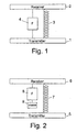
- FIG. 1 illustrates the principles of a first embodiment of the present invention. Vibrations in a transmitter 1 are transmitted to a receiver 2 via a spring coupling 3.
- the spring coupling 3 provides for the mounting of the receiver 2 on the transmitter 1 and provides for a stiff static mount.
- a force actuation arrangement 4 is provided coupled between the transmitter 1 and the receiver 2 in parallel with the spring arrangement 3-Thus in accordance with the principles of this embodiment of the present invention, the vibrations transmitted from the transmitter 1 to the receiver 2 via the spring arrangement 3 are actively controlled by the application of a force to the receiver 2 by the force actuation arrangement 4.
- FIG. 2 illustrates the principles of a second embodiment of the present invention. Vibrations in a transmitter 5 are transmitted to a receiver 6 via a spring arrangement 7.
- the receiver 6 is statically mounted on the transmitter 5 via the spring arrangement 7.
- a force actuation arrangement 8 is provided coupled to the receiver 6.
- a mass 9 is provided coupled to the force actuation arrangement 8.
- the force applied is an inertial force.
- This embodiment of the present invention has the benefit of avoiding a direct connection between the receiver 6 and transmitter 5 through the force actuation arrangement. This, unlike the embodiment of Figure 1 , does not provide a secondary vibration path. However, this embodiment relies on an inertial force.
- Figure 3 is a graph illustrating the transmission response with frequency of a conventional elastomeric mount, a spring mount, and an active mount, all three with the same static stiffness in accordance with an embodiment of the present invention.
- the elastomeric mount however suffers from a frequency dependant stiffness which causes high transmission in the mid and high frequency regions.
- a vibration isolation mount provides for some vibration isolation at high frequencies.
- the elastomeric mount however suffers from resonance at low frequencies and at these frequencies the transmission is high.
- a spring mount provides for an improved isolation at high frequencies.
- a spring mount suffers from strong resonance at low frequencies which, in the example shown in Figure 3 , peaks at 200Hz. Resonance occurs when the isolators' stiffness reacts against the receiving mass.
- the resonant frequency F R is given by:
- the resonant frequency can be shifted to lower frequencies and an improved high frequency isolation can be achieved by increasing the mass, i.e. the blocking mass.
- the mass i.e. the blocking mass.
- the resonant frequency merely moves to lower frequencies but is still present.
- Embodiments of the present invention aim to actively control the vibrations at the low frequency region in order to provide or improve isolation at low frequencies and to ameliorate the effects of resonance in a spring-type mount.
- the effect of the removal of the resonance effect in an active mount in accordance with an embodiment of the present invention is illustrated in Figure 3 .
- the active force controller operates in parallel with the spring arrangement.
- Figure 4 illustrates an embodiment of the present invention in accordance with the principles of the embodiment of Figure 1 in which a transmitting member 10 is mounted to a receiving member 20 by a mount arrangement comprising a spring arrangement 30 illustrated as a helical spring in this embodiment, arranged concentrically around a force actuator 40 connected between the transmitting 10 and the receiving member 20.
- a spring arrangement 30 illustrated as a helical spring in this embodiment, arranged concentrically around a force actuator 40 connected between the transmitting 10 and the receiving member 20.
- FIG 5 illustrates another embodiment of the present invention in accordance with the principles of the embodiment of Figure 2 in which a transmitting member 50 is mounted to a receiving member 60 by a mount arrangement comprising a spring arrangement 70 arranged concentrically around a force actuator 80 which is coupled between the receiving member 60 and a mass 90 which is also arranged concentrically within the spring arrangement 70.
- FIG. 6 illustrates an alternative embodiment of the present invention in accordance with the principles of the embodiment of Figure 1 in which a transmitting member 11 is mounted to a receiving member 21 by a mount arrangement comprising a spring arrangement 31 arranged concentrically within a force actuator 41 connected between the transmitting member 11 and the receiving member 21.
- Figure 7 illustrates an alternative embodiment to the present invention in accordance with the principles of the embodiment of Figure 2 in which a transmitting member 51 is coupled to a receiving member 61 via a spring arrangement 71.
- the spring arrangement 71 is arranged concentrically within a force actuator 81 and a mass 91.
- the force actuator 81 is coupled between the mass 91 and the receiving member 61 to apply a controlling force to the receiving member 61.
- the force actuator will generally require a mass against which to react.
- an electromagnetic actuator there are two mutually moving components comprising a coil member and a magnet member. Either one of these can act as the mass.
- the magnet member comprises a magnetic circuit surrounding the coil member to provide the electromotive force. It is thus convenient for the magnet member to form the mass for providing the inertial force.
- the force actuation arrangement is primarily controlled in accordance with vibrations detected by a reference sensor associated with the transmitting member to provide signals indicative of vibrations to be transmitted through the spring arrangement.
- the control of the force actuation comprises a feedforward control system. Feedforward control systems are well known in the art and require advanced notice of a vibration upstream for control downstream.
- the spring arrangement provides for the delay to enable the reference sensor to detect an upstream vibration component for cancellation downstream, i.e. at the receiving member.
- the spring arrangement can comprise any suitable spring arrangement to provide the delay.
- the spring arrangement can comprise a helical spring or a leaf spring. Any arrangement which preferably provides a stiffness that does not substantially vary with frequency can be used.
- the present invention is not limited to the use of metal springs.
- one of the properties of the spring which provides the delay is the mass per unit length. The length of the spring will also effect the delay. These properties can be independent of the stiffness.
- a light spring can provide the same stiffness as a heavy spring. However, a heavy or long spring provides for a longer delay than a light or short spring.
- a stiff spring is required to provide for a strong static coupling, and the mass per unit length or length is required to be large enough to provide the required delay for feedforward vibration control.
- Other factors that affect the delay in a spring arrangement are other shape and configuration parameters.
- FIG 8 is a schematic diagram of an embodiment of the present invention in accordance with the principles of the embodiment of Figure 1 .
- An active mount 100 is arranged between a transmitting member 12 and a receiving member 22 to mount the receiving member 22 to the transmitting member 12.
- the mount 100 includes couplings 105 and 106 for coupling the mount 100 to the receiving member 22 and the transmitting member 12 respectively.
- a blocking mass 104 is mounted on the coupling 105.
- a spring arrangement 32 is provided between the coupling 106 and the blocking means 104 to stiffly statically mount the receiving member 22 to the transmitting member 12.
- a force actuator arrangement 42 is provided coupled between the blocking mass 104 and the coupling 106 in order to provide the controlling force on the receiving member 22.
- a reference sensor 102 is mounted on the coupling 106 in order to detect vibrations in the transmitting member which are transmitted through the spring arrangement 32 to the receiving member 22.
- a controller 101 is provided for receiving the output of the reference sensor 102 in order for generating a controlling signal to control the force actuator arrangement 42.
- An error sensor 103 is mounted on the coupling 105 for detecting vibrations in the receiving member 22. The output of the error sensor 103 is input to the controller 101 to provide a feedback signal for control of the force actuator arrangement 42.
- the force actuator arrangement is controlled by a controller 101 which carries out a feedforward and feedback control.
- FIG 9 illustrates an embodiment of the present invention in accordance with the principles of the embodiment of Figure 2 .
- a mount 110 mounts a receiving member 62 to a transmitting member 52.
- the mount includes couplings 114 and 115 for coupling the mount 110 to the receiving member 62 and the transmitting member 52 respectively.
- a blocking mass 116 is mounted on the coupling 114.
- a spring arrangement 72 is coupled between the coupling 115 and the blocking mass 116.
- a force actuator 82 is provided coupled to the blocking mass 116 to provide a force to the receiving member 62.
- An inertial mass 92 is provided coupled to the force actuator 82 to enable the force actuator 82 to apply an inertial force to the receiving member 62.
- a controller 111 is provided for generating control signals to control the force actuator 82.
- a reference sensor 112 is mounted on the coupling 115 to detect vibrations in the transmitting member.
- the controller 111 receives signals from the reference sensor 112 and controls the force actuator 82 accordingly.
- An error sensor 113 is mounted on the coupling 114 to detect vibrations in the receiving member 62.
- the controller 111 receives the signals from the error sensor 113 in order to control the force actuator 82 accordingly.
- the controller 111 performs a combined feedforward and feedback control.
- the error sensors can comprise a number of sensors arranged in any suitable position to detect vibrations in the receiving member 62 and the transmitting member 52 respectively. Conveniently, the sensors are arranged within the mount 100 and 110. However, the sensors can be provided for direct mounting on the receiving member 62 and/or the transmitting member 52.
- Figures 8 and 9 are schematic and although the spring and force actuator are illustrated as being side-by-side, they can be positioned in any suitable arrangement for providing for parallel actuation. Conveniently, in order to avoid shear forces between the force applied by the force actuation and the force applied by vibrations through the spring arrangement, the force actuator and the spring arrangement are arranged concentrically as for example illustrated in Figures 4 to 7 .
- the controllers 101 and 111 perform a combined feedforward and feedback control, i.e. an adaptive feedforward control system.
- the controller thus conveniently comprises a programmable device for performing a control algorithm.
- control algorithms are well-known in the art (see for example " Adaptive Signal Processing" by B. Widrow and S. D. Stearns, Prentice Hall Signal Processing Series, (1985 ).
- adaptive feedforward control systems rely on the reference signal not being corrupted by the controlling force. However, this is often not the case due to leakage back of corrupting control signals. This is particularly the case in the example of the embodiment of Figure 1 .
- the controllers 101 and 111 can thus carry out a control algorithm such as that described in UK patent application no. GB 0311085.5 .
- controllers 101 and 111 are illustrated as residing within the mounts 100 and 110, the controllers can be provided separately, i.e. one per mount, or centrally, i.e. one per plurality of mounts.
- the actuator can comprise any suitable actuator such as an electromagnetic actuator, a piezo electric actuator, a hydraulic actuator, a magnetostrictive actuator, an electrostatic actuator, a pneumatic actuator or a thermal expansive actuator.
- a mount is illustrated in Figures 10, 11 and 12 , which comprises a specific detailed embodiment of the schematic embodiment illustrated in Figure 1 .
- the mount 200 comprises a cap 201 for mounting to a receiving member and a coil frame 202 for mounting to a transmitting member.
- the coil frame is cup-shaped and carries an annular coil 203 within an annular channel 204 on an external circumference of the coil frame 202.
- the coil frame 202 is mounted coaxially with the cap 201 and is provided with an aperture 205 for receiving a spring seat 206.
- the spring seat 206 has an inner threaded portion 207 and an annular recess 208 for receiving a helical spring 209.
- the helical spring 209 sits in the annular recess 208, the spring seat 206 and extends axially towards the cap 201.
- the cap 201 is provided with an annular recess 210 for receiving the other end of the helical spring.
- the cap 201 is also provided with an inner threaded portion 211.
- the inner threaded portions 207 and 211 provide for the coupling of the mount 200 to a transmitting member and a receiving member respectively.
- the cap 201 lies within a spring seat sleeve 212 which extends coaxially with the spring 209 towards the spring seat 206.
- a magnet 213 is provided around a circumferential position of a spring seat sleeve adjacent to the magnet 213 there is provided an annular iron member 214 arranged to lie at an inner circumferential position to the coil 203.
- the annular iron member 204 lies to one side of the magnet 213.
- To the other side of the magnet 213 lies a second annular iron member 215 which extends away from the spring seat sleeve 212 and curves around to extend over an end of the coil frame at a distant radial position.
- a third iron member 216 is provided and comprises an annular member lying adjacent to the coil 203 and extending away from the coil 203.
- the second and third iron member 215 and 216 meet each other and are connected at their outer radial positions to form an annular cavity 217 at four quadrant positions around the circumference of the second and third iron members 215 and 216, resilient members 218 are provided for supporting support arm 219.
- the four support arms 219 extend radially from the coil frame 202 and are held in place by a locking ring 220.
- a seal 221 is provided between the coil frame 202 and the third iron member 216 to seal the gap between the coil 203 and the third iron member 216 to thus provide a seal on the unit.
- the helical spring 209 provides for the strong static coupling between the two sides of the mount 200 to thus enable the strong passive coupling of first member to the second member.
- the coil 203 is mechanically coupled to the coil frame 202 which in turn is coupled to the first member, i.e. a transmitting member.
- the first member i.e. a transmitting member.
- the spring 209 provides for a reduction of the transmission vibrations along the axis.
- the application of current to the coil 203 will generate a force which is applied between the coil frame and cap.
- Relative movement between the coil 203 carried on the coil frame 202 and the iron members 214, 215, 216, magnet, spring seat sleeve and cap 201 causes the bending of the support arms 219.
- the support arms 219 have a low stiffness in the axial direction and a strong stiffness in the perpendicular direction. Thus they provide for strong support of the magnetic components in the magnetic circuit formed by the iron members 213, 214 and 215 relative to the coil frame 202. They also provide the stiffness in a shear direction.
- the support arms 219 are mounted in the resilient members 218 to allow for the change in radial length of the support arms 219 caused by the relative axial displacement of the coil frame 202 and the magnetic circuit comprised of the iron members 214, 215 and 216.
- sensor rings 222 and 223 of piezo electric material is provided within the mount for sensing vibrations.
- a first piezo electric sensor 223 is provided in the coil frame 222 for sensing vibrations coming from the first member i.e. the feedforward or reference signal and a second piezo electric sensor 222 is provided in the second iron member 215 for sensing vibrations in the second member i.e. the feedback or error signal.
- the piezo electric sensors 222 and 223 are annular and substantially concentric with the axis of the mount. This enables the sensors to detect the axial vibrations in the first and second members. Any axially symmetric sensing arrangement can be used in place of the ring sensors 222 and 223.
- this embodiment of the present invention provides for a coaxial spring mount and electromagnetic actuator acting between the two sides of the mount.
- the electromagnetic actuator is formed by the coil 203 lying within a magnetic circuit comprised of the iron members 214, 215 and 216 and the magnet 213.
- the coil 213 has an axial length which is greater than the axial length of the third iron member 216. The reason for this is to ensure that the coil 203 always lies within the magnetic field provided between the third iron member 216 and the first iron member 214, i.e. to ensure no edge effects caused by an edge of the coil 203 entering into the field region between the third iron member 216 and the first iron member 214.
- the coil 203 is shown as being sufficiently long in the axial direction so as to ensure no edge ever enters the region between the third iron member and the first iron member, in an alternative embodiment the coil 203 can be shorter in axial length than the third iron member so that an edge of the coil never leaves the field region between the third iron member and the first iron member.
- the magnetic circuit comprised of the iron members 214, 215 and 216 comprises a more massive component than the coil 203 and the coil frame 202.
- the iron members 214, 215 and 216 and the magnet 213 comprise a mass which is coupled to the cap 201 and provides a blocking mass on the receiving end of the mount.
- the mount 200 when the mount 200 is coupled to first and second members to provide active vibration isolation therebetween, the mount 200 is attached by screws to the first and second members.
- the screws thread into the threaded portions 207 and 211.
- the attachment of the mount to the second member is by way of a rotational decoupling device e.g. a pin or ball joint to allow for the shear rotational decoupling of the mounting of the second member to the first member while still supporting shear loads.
- a grommet can be used, which can for example be made out of rubber, for attachment to the second member, i.e. for attachment around the screw threaded into the threaded portion 211.
- the rubber grommet between the thread fitted into the threaded portion 211 and the second member allows for bending, i.e. rotation about any axis and effectively provides a pin joint at the receiving end.
- the mounting of the coil frame 202 via the threaded portion 207 to the first member is stiff.
- a controller for controlling the actuation of the electromagnetic actuator in this embodiment of the present invention can be provided separately or attached to the mount 200.
- An annular casing plate is provided on an axis coaxially with a spring seat 302, a cup-shaped casing body 303 is provided coupled to the casing plate 301 to provide a housing.
- a helical spring 304 extends along the axis.
- the helical spring 304 sits at one end within an annular recess 305 within the spring seat 302.
- the other end of the helical spring 304 lies in annular recess 306 in a second spring seat 307.
- the second spring seat 307 is connected to a cup-shaped coil frame 308.
- the coil frame 308 extends axially over the spring 304.
- An annular coil 309 lies at an outer circumferential position at an axial position along the coil frame 308.
- a magnetic circuit is suspended from the axial end of the coil frame 308 on support arms 310.
- the support arms 310 radially extend from quadrant positions at the axial end of the coil frame 308 and are locked in place at an inner radial position thereof by a locking ring 311.
- the support arms 310 are mounted in resilient members 312.
- the resilient members 312 lie within and support the magnetic circuit. Resilient members 312 are held between a first magnetic member 313 and a second magnetic member 314.
- the first magnetic member 313 comprises a generally annular member extending radially inwards towards the coil 309 to lie adjacent the coil 309.
- the second magnetic member 314 comprises an annular member extending radially inwardly from the resilient members 312 to a radial position inward of the coil frame 308.
- An annular magnet 315 is provided adjacent to the radially inner portion of the second magnetic member 314.
- a third magnetic member 316 comprises an annular member which lies adjacent to the magnet 315 in an axial position.
- the first magnet member 313 and the third magnet member 316 lie in radially opposed positions either side of the annular coil 309.
- the magnetic circuit is relatively heavy compared to the coil frame and the coil and it thus provides the inertial mass suspended by the support arms.
- the electromagnetic actuator includes the inertial mass.
- the resilient members 312 are provided to allow for the radial length variations of the support arms 310 as the electromagnetic actuator causes the relative movement of the magnetic circuit and the coil 309.
- the support arms 310 are low in stiffness in the axial direction and strong in stiffness in the radial direction, thereby providing for support for the magnetic circuit and the inertial mass which in this embodiment comprise the same components.
- a coil frame 308 is connected to a base 317, support arms 318 radially extend from the base 317 and are held to the base 317 at inner radial positions thereof by a locking ring 319. At their outer radial ends the support arms 318 are connected to a resilient support ring 320 which sits on the casing body 303 and is locked in place thereon by a locking ring 321.
- the base 317 is for coupling to the receiving member via a threaded portion 322 to provide for rotation along the axis, the bolt threaded into the threaded portion 322 is threaded through a grommet in the second member so that there is a resilient grommet connection between the second member and the base 317 to provide a pin joint.
- a hole is provided in the casing to allow a bolt to be inserted into a threaded portion 323 in the spring seat 302. The connection made to the transmitting member by the bolt is fixed to provide a solid connection between the casing plate 301 and the spring seat 302 and the transmitting member.
- a reference sensor 331 in the form of a piezoelectric ring is provided mounted on the casing plate 301.
- An error sensor 330 in the form of a piezoelectric ring is provided mounted on the coil frame 308.
- the electromagnetic actuator lies coaxially about the spring.
- the inertial mass lies concentrically around the spring and in this embodiment the inertial mass comprises the magnetic circuit of the electromagnetic actuator.
- the electromagnetic actual components are not physically connected to the transmitting member. There is no coupling with any axial stiffness between the base 317 and the casing plate 301 and the spring seat 302.
- the support arms 318 provide for the axially stiff decoupling of the body 317 and the casing plate 301 (and the spring seat 302). There is thus no axially stiff coupling between the two sides of the mount 300.
- the present invention is primarily concerned with the reduction of transmission of vibrations in a direction perpendicular between two objects or members.
- the present invention has application where it is necessary to mount two bodies and it is desirable to prevent the transfer of vibrations from one body to the other while firmly mounting the bodies together.
- the present invention has particular application in the aircraft industry for the mounting of trim panels to the aircraft air frame.
- boundary layer field pressure fluctuations When an aircraft is flying, around the skin of the aircraft there is generated boundary layer field pressure fluctuations. These pressure fluctuations are generally subsonic and thus they are not well coupled between the airframe and the cabin via the air/insulation gap therebetween. They are instead primarily transmitted through the trim panel mounts which in the prior art have comprised elastomeric members.
- the embodiments of the present invention have a broadband frequency capability and are thus ideally suited to the control of vibrations generated by the turbulent boundary layer pressure variations.
- the active vibration isolation mounts can replace some or all of the conventional passive mounts to provide a reduction of the transmission of vibrations from the airframe to the trim panels.
- Each mount can be controlled independently by a controller either provided with a mount in the unit, or provided separately. Alternatively, a plurality of mounts can be controlled from a single controller.
- a controller receives the reference (feedforward) and error (feedback) signals from the sensors and generates respective control signals. Each mount is controlled independently.
- the mounts can be used as engine mounts for an engine that operates over a wide range of frequencies.
- the use of the active vibration isolation mounts will reduce the transmission of vibrations from the engine to the framework in which the engine is mounted.
- the provision of the active control in the active vibration mount enables control of low frequencies. When an engine is started up, as it begins to start, if no active control is provided, then severe vibration can be transmitted to the framework holding the engine.
- the active vibration isolation mount reduces this vibration.
- the active vibration mount is particularly useful for an engine which is repeatedly started and stopped and thus generates a broad range of vibration frequencies. It can also be used as a mount in an environment subject to broadband combustion flow noise.
- the present invention encompasses not just the active vibration mount and its method of operation, but also the design and manufacture of such a mount.
- sensors must be selected, the actuator must be designed to apply the force to the receiving member and the spring arrangement must be designed to lie between the transmitting member and the receiving member and to provide the necessary delay between the transmitting member and the receiving member to allow for the feedforward control of the generation of the controlling force on the receiving member.
- the design of the mount requires the designing of the spring arrangement to provide such a delay.
- Some of the parameters that can affect delay are the mass per unit length, the length of the spring, the shape of the spring, and the type of spring configuration.
- the spring arrangement comprises a helical spring
- the spring is chosen to provide a mass per unit length and length which is sufficient to provide the required delay.
- a typical delay required for feedforward active control is 200 ⁇ sec. This can readily be achieved by selecting a spring having an appropriate mass per unit length.
- the selection of the spring requires the selection of a spring having a force per unit displacement which remains substantially constant with frequency. Embodiments which use metal springs provide such a requisite response.
- the present invention encompasses any other form of spring means which can provide the required physical behaviour.
- This embodiment of the invention also includes the selection of an appropriate blocking mass and an inertial mass, where used, to provide for efficient vibration isolation.
- the mass, shape and mass distribution or number of masses can be designed appropriately.
- a passive vibration isolation mount is illustrated schematically in figure 16 .
- a first member 1000 is a member through or from which vibrations can be transmitted to a second member 1001 by a mount 1005 for mounting the second member 1001 to the first member in a spaced relationship.
- the mount comprises a spring arrangement 1002 which is coupled at one end thereof to the first member 1000 and a blocking mass 1003 which is positioned between the second member 1001 and the spring arrangement 1003 so as to lie at the other end of the spring arrangement 1002.
- the spring arrangement 1002 provides a spring force between the first member 1000 and second member 1001 via the blocking mass 1003.
- Mounting arrangements 1006 and 1007 are provided for mounting the mount 1005 to the first member 1000 and the second member 1001 respectively.
- the blocking mass 1003 comprises a mass provided in or adjacent to a region between the second member 1001 and the second mounting arrangement 1007 to increase the localised mass of the second member 1001 at the point of mounting of the mount to the second member 1001. This increases the efficiency of the mount.
- the blocking mass can comprise a single mass or a distribution of masses arranged substantially coaxially with the spring arrangement.
- a spring member can be a leaf spring, a coil spring or any other spring material or structure to provide a spring force.
- a vibration absorber is illustrated schematically in figure 17 .
- a blocking mass 2003 is mounted to a member 2001 by a mounting arrangement 2005.
- a spring arrangement 2002 is mounted at one end thereof on the blocking mass 2003.
- the blocking mass 2003 comprises a mass provided in or adjacent to a region between the member 2001 and the vibration absorber to increase the localised mass of the member 2001 at the point of mounting of the absorber to the member 2001. This increases the efficiency of the vibration absorber.
- the blocking mass can comprise a single mass or a distribution of masses arranged substantially coaxially with the spring arrangement.
- This arrangement provides a tuned vibration absorber which more efficiently couples to the member 2001 to absorb vibrations in the member.
- a spring member can be a leaf spring, a coil spring or any other spring material or structure to provide a spring force.
Landscapes
- Engineering & Computer Science (AREA)
- General Engineering & Computer Science (AREA)
- Mechanical Engineering (AREA)
- Aviation & Aerospace Engineering (AREA)
- Physics & Mathematics (AREA)
- Acoustics & Sound (AREA)
- Vibration Prevention Devices (AREA)
- Auxiliary Devices For And Details Of Packaging Control (AREA)
- Motor Or Generator Frames (AREA)
Claims (62)
- Aktive Schwingungsisolierungshalterung (100) für das Befestigen eines ersten Elementes (12) an einem zweiten Element (22) und für das Reduzieren der Übertragung von Schwingungen vom ersten Element (12) zum zweiten Element (22), wobei die aktive Schwingungsisolierungshalterung (100) aufweist:ein erstes Befestigungsmittel (106) für das Befestigen am ersten Element (12);ein zweites Befestigungsmittel (105) für das Befestigen am zweiten Element (22);ein Federmittel (32), das zwischen dem ersten und dem zweiten Befestigungsmittel (106, 105) angeordnet ist;ein Messmittel (102) für das Messen der Schwingungen im ersten Element (12); undein Kraftmittel (42) für das Anwenden einer Steuerungskraft auf das zweite Befestigungsmittel (105) als Reaktion auf ein Steuersignal vom Steuerungsmittel (101), das auf die Schwingungen anspricht, die vom Messmittel (102) gemessen werden;dadurch gekennzeichnet, dass das Federmittel (32) ausgeführt ist, um eine Verzögerung zwischen dem ersten und dem zweiten Befestigungsmittel (106, 105) bereitzustellen, die gleich oder größer ist als eine Verzögerung bei der Anwendung der Steuerungskraft durch das Kraftmittel (42) als Reaktion auf die Schwingungen im ersten Element (12).
- Aktive Schwingungsisolierungshalterung nach Anspruch 1, bei der das Messmittel (102) angeordnet ist, um Schwingungen im ersten Befestigungsmittel (106) zu messen.
- Aktive Schwingungsisolierungshalterung nach Anspruch 1 oder Anspruch 2, bei der das Kraftmittel (42) und das Federmittel (32) parallel funktionieren.
- Aktive Schwingungsisolierungshalterung nach einem der vorhergebenden Ansprüche, bei der das Kraftmittel (42) und das Federmittel (32) im Wesentlichen konzentrisch oder symmetrisch um eine Richtung angeordnet sind, die sich zwischen dem ersten und dem zweiten Befestigungsmittel (106, 105) erstreckt.
- Aktive Schwingungsisolierungshalterung nach einem der vorhergehenden Ansprüche, bei der das Federmitel (32) eine Steifigkeit in einer ersten Richtung aufweist, die sich zwischen dem ersten Befestigungsmittel (106) und dem zweiten Befestigungsmittel (105) erstreckt, die nicht im Wesentliche mit der Frequenz der Schwingungen variiert.
- Aktive Schwingungsisolierungshalterung nach einem der vorhergehenden Ansprüche, bei der das Federmittel (32) eine Masse pro Längeneinheit und eine Länge aufweist, die ausgewählt werden, um die Verzögerung zu liefern.
- aktive Schwingungsisolierungshalterung nach einem der vorhergehenden Ansprüche, bei der die Verzögerung bei der Anwendung der Steuerungskraft durch das Kraftmittel (42) die Verzögerung ist, die durch das Messmittel (102), das Kraftmittel (42) und das Steuerungsmittel (101) gebracht wird.
- Aktive Schwingungsisolierungshalterung nach einem der vorhergehenden Ansprüche, bei der das Messmittel (102), das Federmittel (32) und das Kraftmittel (42) ausgeführt sind, um eine Breitbandschwingungsisolierung zu liefern.
- Aktive Schwingungsisolierungshalterung nach einem der vorhergehenden Ansprüche, bei der das Federmittel (32) eine hohe statische Steifigkeit aufweist, um eine statische steife Befestigung des zweiten Elementes (105) am ersten Element (106) zu bewirken.
- Aktive Schwingungsisolierungshalterung nach einem der vorhergehenden Ansprüche, die ein Fehlermessmittel (103) für das Messen von Schwingungen im zweiten Element (105) einschließt, wobei das Kraftmittel (42) ausgeführt ist, um eine Steuerungskraft auf das zweite Befestigungsmittel (105) als Reaktion auf ein Steuersignal vom Steuerungsmittel (101) anzuwenden, das auf die Schwingungen anspricht, die durch das Messmittel (102) und das Fehlermessmittel (103) gemessen werden.
- Aktive Schwingungsisolierungshalterung nach einem der vorhergehenden Ansprüche, bei der das Federmittel (32) mindestens eine Feder aufweist.
- Aktive Schwingungsisolierungshalterung nach einem der vorhergehenden Ansprüche, bei der das Federmittel (32) mindestens eine Schraubenfeder aufweist.
- Aktive Schwingungsisolierungshalterung nach einem der vorhergehenden Ansprüche, bei der das Kraftmittel (42) zwischen dem ersten Befestigungsmittel (106) und dem zweiten Befestigungsmittel (105) geschaltet ist, um die Steuerungskraft auf das zweite Befestigungsmittel (105) anzuwenden.
- Aktive Schwingungsisolierungshalterung nach Anspruch 13, bei der das Kraftmittel (42) ein elektromagnetisches Betätigungselement aufweist.
- Aktive Schwingungsisolierungshalterung nach Anspruch 14, bei der das elektromagnetische Betätigungselement ein Spulenelement, das mit dem ersten Befestigungsmittel (106) gekoppelt ist, und ein magnetisches Element aufweist, das mit dem zweiten Befestigungsmittel (105) gekoppelt ist.
- Aktive Schwingungsisolierungshalterung nach Anspruch 15, bei der das magnetische Element schwerer ist als das Spulenelement und eine Blockiermasse liefert, die mit dem zweiten Befestigungsmittel (105) verbunden ist.
- Aktive Schwingungsisolierungshalterung nach Anspruch 15 oder Anspruch 16, bei der das Spulenelement und das magnetische Element durch ein Kopplungsmitlel gekoppelt sind, das eine geringe Steifigkeit in einer ersten Richtung, die sich zwischen dem ersten und dem zweiten Befestigungsmittel (106, 105) erstreckt, und eine hohe Steifigkeit in einer senkrechten Richtung liefert.
- Aktive Schwingungsisolierungshalterung nach einem der Ansprüche 13 bis 17, die eine Blockiermasse einschließt, die mit dem zweiten Befestigungsmittel (105) gekoppelt ist.
- Aktive Schwingungsisolierungshalterung nach einem der Ansprüche 1 bis 12, die eine Blockiermasse einschließt, wobei das Kraftmittel (42) zwischen der Blockiermasse und dem zweiten Befestigungsmittel (105) geschaltet ist, um die Steuerungskraft auf das zweite Befestigungsmittel (105) anzuwenden.
- Aktive Schwingungsisolierungshalterung nach Anspruch 19, bei der das Kraftmittel (42) ein elektromagnetisches Betätigungselement aufweist.
- Aktive Schwingungsisolierungshalterung nach Anspruch 20, bei der das elektromagnetische Betätigungselement ein Spulenelement und ein magnetisches Element aufweist und das Spulenelement oder das magnetische Element die Blockiermasse aufweist.
- Aktive Schwingungsisolierungshalterung nach Anspruch 21, bei der das magnetische Element die Blockiermasse aufweist und das Spurenelement mit dem zweiten Befestigungsmittel (105) gekoppelt ist.
- Aktive Schwingungsisolierungshalterung nach Anspruch 21 oder Anspruch 22, bei der das Spulenelement und das magnetische Element durch ein Kopplungsmittel gekoppelt sind, das eine geringe Steifigkeit in einer ersten Richtung, die sich zwischen dem ersten und dem zweiten Befestigungsmittel (106, 105) erstreckt, und eine hohe Steifigkeit in einer senkrechten Richtung liefert.
- Aktive Schwingungsisolierungshaterung nach einem der vorhergehenden Ansprüche, bei der das zweite Befestigungsmittel (105) ein Drehgelenk für das Befestigen am zweiten Element einschließe um die Halterung vom zweiten Element für alle Schwingungsarten mit Ausnahme der Schwingung in der Richtung zwischen dem ersten und dem zweiten Element (12, 22) zu isolieren.
- Aktive Schwingungsisolierungshalterungsanordnung, die aufweist: eine aktive Schwingungsisolierungshalterung (100) nach einem der vorhergehenden Ansprüche; und ein Steuerungsmittel (101) für das Erzeugen des Steuersignals als Reaktion auf die Schwingungen, die vom Messmittel (102) gemessen wurden.
- Aktive Schwingungsisolierungshalterungsanordnung, die aufweist: eine Vielzahl von aktiven Schwingungsisolierungshalterungen (100) nach einem der Ansprüche 1 bis 24; und ein Steuerungsmittel (101) für das Erzeugen von Steuersignalen für die Kraftmittel als Reaktion auf die Schwingungen, die von einem jeden entsprechenden Messmittel (102) gemessen wurden.
- Verfahren zum Steuern der Schwingungen, die von einem ersten Element (12) auf ein zweites Element (22) übertragen werden, wenn das zweite Element (22) am ersten Element (12) bei Verwendung einer Federanordnung (32) befestigt ist, die eine Verzögerung bei der Übertragung eines Impulses zwischen dem ersten und dem zweiten Element (12, 22) liefert, wobei das Verfahren die folgenden Schritte aufweist:Messen der Schwingungen im ersten Element (12); undAnwenden einer Kraft am zweiten Element (22) als Reaktion auf die gemessenen Schwingungen, um die Schwingungen im zweiten Element (22) zu reduzieren;dadurch gekennzeichnet, dass die Federanordnung (32) eine Verzögerung gleich einer oder größer als eine Verzögerung bei der Bereitstellung der Kraft als Reaktion auf die Schwingungen im ersten Element liefert.
- Verfahren nach Anspruch 27, bei dem die Federanordnung (32) am ersten Element (12) bei Verwendung eines ersten Befestigungsmittels (106) befestigt ist und das Messen den Schritt des Messens der Schwingungen im ersten Befestigungsmittel (106) aufweist.
- Verfahren nach Anspruch 27 oder Anspruch 28, bei dem die Kraft und die Federanordnung (32) parallel funktionieren.
- Verfahren nach einem der Ansprüche 27 bis 29, bei dem die Kraft im Wesentlichen konzentrisch mit der Federanordnung (32) angewandt wird.
- Verfahren nach einem der Ansprüche 27 bis 30, bei dem die Federanordnung (32) so ausgewählt wird, dass sie eine Steifigkeit in einer ersten Richtung aufweist, die sich zwischen einer Befestigungsposition am ersten Element (12) und einer Befestigungsposition am zweiten Element (22) erstreckt, die nicht im Wesentlichen mit der Frequenz der Schwingungen variiert.
- Verfahren nach einem der Ansprüche 27 bis 31, bei dem die Federanordnung (32) so ausgewählt wird, dass sie eine Masse pro Längeneinheit und eine Länge aufweist, um die Verzögerung zu liefern.
- Verfahren nach einem der Ansprüche 27 bis 32, bei dem die Verzögerung bei der Anwendung der Steuerungskraft die Verzögerung ist, die durch das Messen gebracht wird, und die Abwendung der Kraft als Reaktion auf die Schwingungen im ersten Element (12).
- Verfahren nach einem der Ansprüche 27 bis 33, bei dem eine Breitbandschwingungsisolierung gclicfcrt wird.
- Verfahren nach einem der Ansprüche 27 bis 34, bei dem die Federanordnung (32) so ausgewählt wird, dass sic eine hohe statische Stcifigkcit aufweist, um die statische steife Befestigung des zweiten Elementes (22) am ersten Element (12) zu bewirken.
- Verfahren nach einem der Ansprüche 27 bis 35, das den Schritt des Messens von Schwingungen im zweiten Element (22) einschließt, wobei die Kraft auf das zweite Element (22) als Reaktion auf die Schwingungen, die im ersten Element (12) gemessen werden, und die Schwingungen angewandt wird, die im zweiten Element (22) gemessen werden.
- Verfahren nach einem der Ansprüche 27 bis 36, bei dem die Federanordnung (32) mindestens eine Feder aufweist.
- Verfahren nach einem der Ansprüche 27 bis 37, bei dem die Federanordnung (32) mindestens eine Schraubenfeder aufweist.
- Verfahren nach einem der Ansprüche 27 bis 38, bei dem die Kraft vom ersten Element (12) auf das zweite Element (22) abgewandt wird.
- Verfahren nach Anspruch 39, bei dem die Kraft bei Benutzung eines elektromagnetischen Betätigungselementes angewandt wird.
- Verfahren nach Anspruch 40, bei dem das elektromagnetische Betätigungselement ein Spulenelement, das mit dem ersten Element (12) gekoppelt ist, und ein magnetisches Element aufweist, das mit dem zweiten Element (22) gekoppelt ist.
- Verfahren nach Anspruch 41, bei dem das magnetische Element schwerer ist als das Spulenelement und eine Blockiermasse liefert, die mit dem zweiten Element (22) verbunden ist.
- Verfahren nach Anspruch 40 oder Anspruch 41, bei dem das Spulenelement und das magnetische Element durch ein Kopplungsmittel gekoppelt sind, das eine niedrige Steifigkeit in einer ersten Richtung, die sich zwischen dem ersten und dem zweiten Element (12, 22) erstreckt, und eine hohe Steifigkeit in einer senkrechten Richtung liefert.
- Verfahren nach einem der Ansprüche 39 bis 43, bei dem eine Blockiermasse mit dem zweiten Element (22) gekoppelt ist.
- Verfahren nach einem der Ansprüche 27 bis 38, bei dem die Kraft von einer Blockiermasse auf das zweite Element (22) angewandt wird.
- Verfahren nach Anspruch 45, bei dem die Kraft bei Benutzung eines elektromagnetischen Betätigungselementes angewandt wird.
- Verfahren nach Anspruch 46, bei dem das elektromagnetische Betätigungselement ein Spulenelement und ein magnetisches Element aufweist und das Spulenelement oder das magnetische Element eine träge Masse aufweist.
- Verfahren nach Anspruch 47, bei dem das magnetische Element die träge Masse aufweist und das Spulenelement mit dem zweiten Element (22) gekoppelt ist.
- Verfahren nach Anspruch 47 oder Anspruch 48, bei dem das Spulenelement und das magnetische Element durch ein Kupplungsmittel gekoppelt sind, das eine niedrige Steifigkeit in einer ersten Richtung, die sich zwischen dem ersten und dem zweiten Element (12, 22) ersteckt, und eine hohe Steifigkeit in einer senkrechten Richtung liefert.
- Aktives Schwingungsisolierungsverfahren, das ein Verfahren nach einem der Ansprüche 27 bis 48 aufweist und ein Steuersignal als Reaktion auf die gemessenen Schwingungen für das Steuern der Anwendung der Kraft erzeugt.
- Verfahren nach einem der Ansprüche 27 bis 50 für das Isolieren einer Trimmfläche (Trim-Panel), die an einem Flugzeugkörper montiert ist, von Schwingungen im Flugzeugkörper, die durch ein Unterschallgrenzschichtgeräusch hervorgerufen werden, indem eine Trimmhalterung benutzt wird, die eine Federanordnung (32) einschließt, um eine Verzögerung bei der Übertragung eines Impulses zwischen der Trimmfläche und dem Flugzeugkörper zu bewirken, wobei das erste Element der Flugzeugkörper und das zweite Element die Trimmfläche sind.
- Verfahren nach Anspruch 51, bei dem eine Federanordnung (32) am Flugzeugkörper bei Verwerdung einer ersten Halterung befestigt ist, und wobei das Messen den Schritt des Messens von Schwingungen in der ersten Halterung aufweist.
- Verfahren für das Konstruieren einer aktiven Halterungsanordnung für das Befestigen eines ersten Elementes (12) an einem zweiten Element (22), das die folgenden Schritte aufweist:Auswählen eines Sensors (102) für das Messen von Schwingungen im ersten Element (12);Konstruieren einer Betätigungselementanordnung (42) für das Liefern einer Kraft am zweiten Element (22);Auswählen eines aktiven Kraftreglers (101) für das Steuern des Betätigungselementes (42) als Reaktion auf die gemessenen Schwingungen, um die Schwingungen im zweiten Element (22) zu reduzieren; undKonstruieren eines Federelementes (32) für eine Bereitstellung zwischen dem ersten und dem zweiten Element (12, 22), um eine Verzögerung bei der Übertragung eines Impulses zwischen dem ersten und dem zweiten Element (12, 22) gleich einer oder größer als eine Verzögerung zu bewirken, die durch den Sensor (102), das Betätigungselement (42) und den aktiven Kraftregler (101) bei der Bereitstellung der Kraft als Reaktion auf die Schwingungen im ersten Element (12) gebracht wird.
- Verfahren nach Anspruch 53, bei dem der aktive Kraftregler (101) and das Federelement (32) so konstruiert sind, dass sie parallel funktionieren.
- Verfahren nach Anspruch 53 oder Anspruch 54, bei dem der aktive Kraftregler (101) und das Federelement (32) so konstruiert sind, dass sie im Wesentlichen konzentrisch liegen.
- Verfahren nach einem der Ansprüche 53 bis 55, bei dem das Federelement (32) so konstruiert ist, dass es eine Steifigkeit in einer ersten Richtung aufweist, die sich zwischen dem ersten Element (12) und dem zweiten Element (22) erstreckt, die nicht im Wesentlichen mit der Frequenz der Schwingungen variiert.
- Verfahren nach einem der Ansprüche 53 bis 56, bei dem das Federelement (32) so konstruiert ist, dass es eine Masse pro Längeneinheit und eine Länge aufweist, um die Verzögerung zu liefern.
- Verfahren nach einem der Ansprüche 53 bis 57, bei dem die Verzögerung die Verzögerung ist, die durch den Sensor (102), den aktiven Kraftregler (101) und das Betätigungselement (42) gebracht wird.
- Verfahren nach einem der Ansprüche 53 bis 58, bei dem der Sensor (102), das Federelement, der aktive Kraftregler (101) und das Betätigungselement (42) ausgeführt sind, um eine Breitbandschwingungsisolierung zu liefern.
- Verfahren nach einem der Ansprüche 53 bis 59, bei dem das Federelement (32) so konstruiert ist, dass es eine hohe statische Steifigkeit aufweist, um die statische steife Befestigung des ersten Elementes (12) am zweiten Element (22) zu bewirken.
- Verfahren nach einem der Ansprüche 53 bis 60, bei dem das Betätigungselement (42) so konstruiert ist, dass es zwischen dem ersten Element (12) und dem zweiten Element (22) geschaltet ist, um die Kraft auf das zweite Element (22) anzuwenden.
- verfahren nach einem der Ansprüche 53 bis 61, das die Schritte des Auswählens einer Blockiermasse und des Konstruierens des Betätigungselementes (42) so einschließt, dass es zwischen die Blockiermasse und das zweite Element (22) geschaltet wird, um die Kraft auf das zweite Element (22) anzuwenden.
Applications Claiming Priority (2)
| Application Number | Priority Date | Filing Date | Title |
|---|---|---|---|
| GB0318690A GB2404716B (en) | 2003-08-08 | 2003-08-08 | A vibration isolation mount and method |
| PCT/GB2004/003220 WO2005017386A2 (en) | 2003-08-08 | 2004-07-26 | A vibration isolation mount and method |
Publications (2)
| Publication Number | Publication Date |
|---|---|
| EP1668271A2 EP1668271A2 (de) | 2006-06-14 |
| EP1668271B1 true EP1668271B1 (de) | 2009-01-14 |
Family
ID=27839912
Family Applications (1)
| Application Number | Title | Priority Date | Filing Date |
|---|---|---|---|
| EP04743550A Not-in-force EP1668271B1 (de) | 2003-08-08 | 2004-07-26 | Schwingungsisolierungshalterung und -verfahren |
Country Status (6)
| Country | Link |
|---|---|
| US (1) | US7665708B2 (de) |
| EP (1) | EP1668271B1 (de) |
| AT (1) | ATE421051T1 (de) |
| DE (1) | DE602004019119D1 (de) |
| GB (1) | GB2404716B (de) |
| WO (1) | WO2005017386A2 (de) |
Cited By (1)
| Publication number | Priority date | Publication date | Assignee | Title |
|---|---|---|---|---|
| EP3106710A1 (de) | 2015-06-15 | 2016-12-21 | Airbus Defence and Space GmbH | Schwingungsdämpfervorrichtung |
Families Citing this family (38)
| Publication number | Priority date | Publication date | Assignee | Title |
|---|---|---|---|---|
| US7983813B2 (en) | 2004-10-29 | 2011-07-19 | Bose Corporation | Active suspending |
| US8095268B2 (en) * | 2004-10-29 | 2012-01-10 | Bose Corporation | Active suspending |
| US8439299B2 (en) | 2005-12-21 | 2013-05-14 | General Electric Company | Active cancellation and vibration isolation with feedback and feedforward control for an aircraft engine mount |
| EP1870614B1 (de) * | 2006-06-23 | 2010-10-20 | Integrated Dynamics Engineering GmbH | Aktives Schwingungsisolationssystem mit verbesserter Sensoren-/Aktorenabstimmung |
| GB2447231B (en) * | 2007-03-05 | 2012-03-07 | Ultra Electronics Ltd | Active tuned vibration absorber |
| WO2008116897A1 (de) | 2007-03-27 | 2008-10-02 | Basf Se | Verfahren zur herstellung von farblosen isocyanuraten von diisocyanaten |
| EP2020263B1 (de) * | 2007-07-27 | 2014-05-07 | F.Hoffmann-La Roche Ag | Etikett zur Ausrichtungserkennung, Trägerstruktur für einen Reagenzbehälter und Analysegerät |
| US7962261B2 (en) | 2007-11-12 | 2011-06-14 | Bose Corporation | Vehicle suspension |
| US8037821B2 (en) * | 2008-04-24 | 2011-10-18 | Raytheon Company | Methods and apparatus for reducing the transmission of mechanical waves |
| US20100030384A1 (en) * | 2008-07-29 | 2010-02-04 | Technical Manufacturing Corporation | Vibration Isolation System With Design For Offloading Payload Forces Acting on Actuator |
| WO2010046327A1 (de) | 2008-10-22 | 2010-04-29 | Basf Se | Verfahren zur herstellung farbloser polyisocyanate |
| GB2478790B (en) * | 2010-03-19 | 2016-06-15 | Univ Southampton | Apparatus and method of vibration control |
| DE102010048243A1 (de) * | 2010-10-12 | 2012-04-12 | Airbus Operations Gmbh | Haltevorrichtung für Innenverkleidungsteile einer Flugzeugzelle und Befestigungssystem mit solchen Haltevorrichtungen |
| US8534594B2 (en) | 2011-04-11 | 2013-09-17 | Gulfstream Aerospace Corporation | Vibration isolation system using electrical cables as mass |
| US9068815B1 (en) * | 2011-11-09 | 2015-06-30 | Sturman Industries, Inc. | Position sensors and methods |
| EP2639475B1 (de) * | 2012-03-16 | 2015-04-29 | Wölfel Beratende Ingenieure GmbH & Co. KG | Tilgeranordnung |
| US8899393B2 (en) | 2012-06-08 | 2014-12-02 | Technical Manufacturing Corporation | Active vibration isolation system |
| CN102734379B (zh) * | 2012-06-09 | 2013-12-11 | 哈尔滨工业大学 | 基于电磁与静压气浮复合支撑的主动隔振装置 |
| JP6002049B2 (ja) * | 2013-01-16 | 2016-10-05 | 本田技研工業株式会社 | 能動型防振支持装置の制御装置 |
| US9617918B2 (en) | 2014-01-13 | 2017-04-11 | The Boeing Company | Bracket for mounting/removal of actuators for active vibration control |
| US9174739B2 (en) | 2014-01-13 | 2015-11-03 | The Boeing Company | Active vibration control system |
| EP2998611B1 (de) * | 2014-09-18 | 2019-07-24 | Integrated Dynamics Engineering GmbH | Schwingungsisolator mit pneumatischer Feder |
| US10184539B2 (en) | 2014-09-30 | 2019-01-22 | Technical Manufacturing Corporation | Vibration isolation system |
| US9846425B2 (en) | 2015-03-31 | 2017-12-19 | Bose Corporation | Retrieving pre-determined controller parameters to isolate vibrations in an authorized payload |
| US9618077B2 (en) | 2015-07-23 | 2017-04-11 | Honeywell International Inc. | Isolators including main spring linear guide systems |
| EP3260732B1 (de) * | 2016-06-23 | 2019-03-27 | Integrated Dynamics Engineering GmbH | Pneumatischer aktor sowie verfahren zum betrieb eines aktiven schwingungsisolationssystem |
| AT518871B1 (de) * | 2016-08-26 | 2018-02-15 | Univ Wien Tech | Vorrichtung zur schwingungsisolierten aufhängung einer last |
| JP7225210B2 (ja) | 2017-08-15 | 2023-02-20 | テクニカル・マニュファクチャリング・コーポレイション | 床フィードフォワード補助を備えた精密振動絶縁システム |
| CN107654552B (zh) * | 2017-08-31 | 2019-07-16 | 哈尔滨工程大学 | 一种采用压电片进行对中性调节的准零刚度隔振器 |
| US10752298B2 (en) | 2018-08-31 | 2020-08-25 | Cnh Industrial America Llc | Vibration dampening system for a work vehicle with elastomeric dampers |
| US10710645B2 (en) | 2018-08-31 | 2020-07-14 | Cnh Industrial America Llc | Vibration dampening system for a work vehicle with chassis dampers |
| US10960936B2 (en) | 2018-08-31 | 2021-03-30 | Cnh Industrial America Llc | Vibration dampening system for a work vehicle with cab dampers |
| US11422210B2 (en) * | 2019-10-10 | 2022-08-23 | Honeywell International Inc. | Apparatuses, systems, and methods for weight detection |
| EP3848613A1 (de) | 2020-01-10 | 2021-07-14 | Siemens Aktiengesellschaft | An einer rahmenkonstruktion elastisch befestigte elektrische maschine |
| WO2022171842A1 (en) * | 2021-02-12 | 2022-08-18 | FSD Active Limited | Vibration control |
| CN114291248B (zh) * | 2021-10-28 | 2023-11-10 | 镇江市逸帆航空部件有限公司 | 一种具有减振功能的机舱用吸音板 |
| CN115571378B (zh) * | 2022-10-09 | 2024-05-07 | 沈阳航空航天大学 | 一种用于在轨航天器微振动的复合式振动控制装置 |
| CN116816863B (zh) * | 2023-08-31 | 2023-11-28 | 山西氢电科技有限公司 | 能量智能控制装置、控制系统及缓冲控制方法 |
Family Cites Families (19)
| Publication number | Priority date | Publication date | Assignee | Title |
|---|---|---|---|---|
| US3490556A (en) * | 1968-01-15 | 1970-01-20 | Mc Donnell Douglas Corp | Aircraft cabin noise reduction system with tuned vibration absorbers |
| NL7105264A (de) * | 1971-04-19 | 1972-10-23 | ||
| AU7190981A (en) * | 1980-06-22 | 1982-03-04 | Kazuto Seto | Vibration isolation type handle device |
| US4531699A (en) * | 1982-07-15 | 1985-07-30 | The Boeing Company | Active vibration isolator |
| JPH07106005B2 (ja) * | 1988-12-02 | 1995-11-13 | 川崎重工業株式会社 | 車両のリニアモータ支持装置 |
| DE3902603C2 (de) * | 1989-01-28 | 1994-01-27 | Continental Ag | Elastische Lagerung, insbesondere Kraftfahrzeug-Motorlager |
| US5000415A (en) * | 1989-11-08 | 1991-03-19 | Newport Corporation | Active vibration isolation systems |
| GB9015983D0 (en) * | 1990-07-20 | 1990-09-05 | Anvt Europ Limited | Electromagnetic actuator |
| WO1994018616A1 (en) * | 1993-02-09 | 1994-08-18 | Noise Cancellation Technologies, Inc. | High transmission loss panel |
| US5427347A (en) * | 1993-04-08 | 1995-06-27 | Lord Corporation | Apparatus for controlling active mounts |
| JPH08247218A (ja) * | 1995-03-07 | 1996-09-24 | Komatsu Ltd | 回転軸の回転変動およびねじり振動抑制装置 |
| US5582385A (en) * | 1995-04-27 | 1996-12-10 | The Lubrizol Corporation | Method for controlling motion using an adjustable damper |
| US5713438A (en) * | 1996-03-25 | 1998-02-03 | Lord Corporation | Method and apparatus for non-model based decentralized adaptive feedforward active vibration control |
| JPH09280307A (ja) * | 1996-04-10 | 1997-10-28 | Nissan Motor Co Ltd | 車両用能動型振動制御装置 |
| US6378672B1 (en) * | 1998-10-13 | 2002-04-30 | Canon Kabushiki Kaisha | Active vibration isolation device and its control method |
| BR0008384A (pt) * | 1999-02-22 | 2003-08-26 | Cooper Tire & Rubber Co | Aparelho para atenuação de vibrações usando atuação eletrônica e eletromagnética |
| DE19930725C1 (de) * | 1999-07-05 | 2001-01-25 | Freudenberg Carl Fa | Lager |
| GB2367110A (en) * | 2000-09-15 | 2002-03-27 | Ultra Electronics Ltd | A vibration isolation mount |
| DE10361481B4 (de) * | 2003-07-22 | 2006-08-17 | Fraunhofer-Gesellschaft zur Förderung der angewandten Forschung e.V. | Modulare Schnittstelle zum Dämpfen mechanischer Schwingungen |
-
2003
- 2003-08-08 GB GB0318690A patent/GB2404716B/en not_active Expired - Lifetime
-
2004
- 2004-07-26 WO PCT/GB2004/003220 patent/WO2005017386A2/en active Application Filing
- 2004-07-26 EP EP04743550A patent/EP1668271B1/de not_active Not-in-force
- 2004-07-26 AT AT04743550T patent/ATE421051T1/de not_active IP Right Cessation
- 2004-07-26 DE DE602004019119T patent/DE602004019119D1/de active Active
-
2006
- 2006-02-06 US US11/348,508 patent/US7665708B2/en active Active
Cited By (1)
| Publication number | Priority date | Publication date | Assignee | Title |
|---|---|---|---|---|
| EP3106710A1 (de) | 2015-06-15 | 2016-12-21 | Airbus Defence and Space GmbH | Schwingungsdämpfervorrichtung |
Also Published As
| Publication number | Publication date |
|---|---|
| WO2005017386A3 (en) | 2005-04-21 |
| ATE421051T1 (de) | 2009-01-15 |
| US7665708B2 (en) | 2010-02-23 |
| DE602004019119D1 (de) | 2009-03-05 |
| GB2404716A (en) | 2005-02-09 |
| GB2404716B (en) | 2007-07-25 |
| GB0318690D0 (en) | 2003-09-10 |
| EP1668271A2 (de) | 2006-06-14 |
| WO2005017386A2 (en) | 2005-02-24 |
| US20070001354A1 (en) | 2007-01-04 |
Similar Documents
| Publication | Publication Date | Title |
|---|---|---|
| EP1668271B1 (de) | Schwingungsisolierungshalterung und -verfahren | |
| EP2180203B1 (de) | Schwingungsisolatoren | |
| CA2665700C (en) | Vibration-attenuating hard-mounted pylon | |
| US5884736A (en) | Active dual reaction mass absorber for vibration control | |
| EP1249633A2 (de) | Schwingungsisolator | |
| RU2303722C1 (ru) | Виброизолятор с переменной структурой демпфирования | |
| JP2010112555A5 (de) | ||
| WO1998044275A9 (en) | Active dual reaction mass absorber for vibration control | |
| JP2009115312A (ja) | 防振デバイス、およびこの防振デバイスを具備する車両 | |
| JP3978908B2 (ja) | 防振支持装置 | |
| US7114711B2 (en) | Smart isolation mounts with continuous structural elements featuring vibration energy management | |
| GB2432403A (en) | Vibration isolation mount | |
| EP1571369B1 (de) | Flüssigkeits- und Elastomereinrichtung mit diskretem Volumenkompensator und sekündärem Angleichselement | |
| GB2432404A (en) | Vibration isolation mount and vibration absorber | |
| EP1857706B1 (de) | Montagevorrichtung für ein schwingunsempfindliches Modul | |
| CN208364669U (zh) | 刚度及阻尼可调的半主动隔振系统 | |
| Hansmann et al. | Tuneable spring element for an adaptable vibration absorber | |
| EP3848606A1 (de) | Verriegelungsisolator und verfahren zum isolieren eines systems | |
| JP4236752B2 (ja) | 支持マウント | |
| JP3690220B2 (ja) | 能動型制振器 | |
| JP3409685B2 (ja) | 防振支持装置 | |
| WO2005015048A2 (en) | Vibration isolator with reflective external travel restrictor and compressive snubber | |
| JPH10252817A (ja) | 防振支持装置 | |
| JP3412500B2 (ja) | 防振支持装置 | |
| JP3846086B2 (ja) | 防振支持装置及びそれを搭載した車両 |
Legal Events
| Date | Code | Title | Description |
|---|---|---|---|
| PUAI | Public reference made under article 153(3) epc to a published international application that has entered the european phase |
Free format text: ORIGINAL CODE: 0009012 |
|
| 17P | Request for examination filed |
Effective date: 20060123 |
|
| AK | Designated contracting states |
Kind code of ref document: A2 Designated state(s): AT BE BG CH CY CZ DE DK EE ES FI FR GB GR HU IE IT LI LU MC NL PL PT RO SE SI SK TR |
|
| R17D | Deferred search report published (corrected) |
Effective date: 20060330 |
|
| DAX | Request for extension of the european patent (deleted) | ||
| 17Q | First examination report despatched |
Effective date: 20070222 |
|
| GRAP | Despatch of communication of intention to grant a patent |
Free format text: ORIGINAL CODE: EPIDOSNIGR1 |
|
| RBV | Designated contracting states (corrected) |
Designated state(s): AT BE BG CH CY CZ DE DK EE ES FI FR GR HU IE IT LI LU MC NL PL PT RO SE SI SK TR |
|
| GRAS | Grant fee paid |
Free format text: ORIGINAL CODE: EPIDOSNIGR3 |
|
| RBV | Designated contracting states (corrected) |
Designated state(s): AT BE BG CH CY CZ DE DK EE ES FI FR GR HU IE IT LI LU MC NL PL PT RO SE SI SK TR |
|
| GRAA | (expected) grant |
Free format text: ORIGINAL CODE: 0009210 |
|
| AK | Designated contracting states |
Kind code of ref document: B1 Designated state(s): AT BE BG CH CY CZ DE DK EE ES FI FR GR HU IE IT LI LU MC NL PL PT RO SE SI SK TR |
|
| REG | Reference to a national code |
Ref country code: CH Ref legal event code: EP |
|
| REG | Reference to a national code |
Ref country code: IE Ref legal event code: FG4D |
|
| REF | Corresponds to: |
Ref document number: 602004019119 Country of ref document: DE Date of ref document: 20090305 Kind code of ref document: P |
|
| PG25 | Lapsed in a contracting state [announced via postgrant information from national office to epo] |
Ref country code: NL Free format text: LAPSE BECAUSE OF FAILURE TO SUBMIT A TRANSLATION OF THE DESCRIPTION OR TO PAY THE FEE WITHIN THE PRESCRIBED TIME-LIMIT Effective date: 20090114 |
|
| NLV1 | Nl: lapsed or annulled due to failure to fulfill the requirements of art. 29p and 29m of the patents act | ||
| PG25 | Lapsed in a contracting state [announced via postgrant information from national office to epo] |
Ref country code: ES Free format text: LAPSE BECAUSE OF FAILURE TO SUBMIT A TRANSLATION OF THE DESCRIPTION OR TO PAY THE FEE WITHIN THE PRESCRIBED TIME-LIMIT Effective date: 20090425 Ref country code: FI Free format text: LAPSE BECAUSE OF FAILURE TO SUBMIT A TRANSLATION OF THE DESCRIPTION OR TO PAY THE FEE WITHIN THE PRESCRIBED TIME-LIMIT Effective date: 20090114 Ref country code: SI Free format text: LAPSE BECAUSE OF FAILURE TO SUBMIT A TRANSLATION OF THE DESCRIPTION OR TO PAY THE FEE WITHIN THE PRESCRIBED TIME-LIMIT Effective date: 20090114 |
|
| PG25 | Lapsed in a contracting state [announced via postgrant information from national office to epo] |
Ref country code: AT Free format text: LAPSE BECAUSE OF FAILURE TO SUBMIT A TRANSLATION OF THE DESCRIPTION OR TO PAY THE FEE WITHIN THE PRESCRIBED TIME-LIMIT Effective date: 20090114 Ref country code: PL Free format text: LAPSE BECAUSE OF FAILURE TO SUBMIT A TRANSLATION OF THE DESCRIPTION OR TO PAY THE FEE WITHIN THE PRESCRIBED TIME-LIMIT Effective date: 20090114 Ref country code: SE Free format text: LAPSE BECAUSE OF FAILURE TO SUBMIT A TRANSLATION OF THE DESCRIPTION OR TO PAY THE FEE WITHIN THE PRESCRIBED TIME-LIMIT Effective date: 20090414 |
|
| PG25 | Lapsed in a contracting state [announced via postgrant information from national office to epo] |
Ref country code: BE Free format text: LAPSE BECAUSE OF FAILURE TO SUBMIT A TRANSLATION OF THE DESCRIPTION OR TO PAY THE FEE WITHIN THE PRESCRIBED TIME-LIMIT Effective date: 20090114 |
|
| PG25 | Lapsed in a contracting state [announced via postgrant information from national office to epo] |
Ref country code: EE Free format text: LAPSE BECAUSE OF FAILURE TO SUBMIT A TRANSLATION OF THE DESCRIPTION OR TO PAY THE FEE WITHIN THE PRESCRIBED TIME-LIMIT Effective date: 20090114 Ref country code: CZ Free format text: LAPSE BECAUSE OF FAILURE TO SUBMIT A TRANSLATION OF THE DESCRIPTION OR TO PAY THE FEE WITHIN THE PRESCRIBED TIME-LIMIT Effective date: 20090114 Ref country code: DK Free format text: LAPSE BECAUSE OF FAILURE TO SUBMIT A TRANSLATION OF THE DESCRIPTION OR TO PAY THE FEE WITHIN THE PRESCRIBED TIME-LIMIT Effective date: 20090114 |
|
| PLBE | No opposition filed within time limit |
Free format text: ORIGINAL CODE: 0009261 |
|
| STAA | Information on the status of an ep patent application or granted ep patent |
Free format text: STATUS: NO OPPOSITION FILED WITHIN TIME LIMIT |
|
| PG25 | Lapsed in a contracting state [announced via postgrant information from national office to epo] |
Ref country code: RO Free format text: LAPSE BECAUSE OF FAILURE TO SUBMIT A TRANSLATION OF THE DESCRIPTION OR TO PAY THE FEE WITHIN THE PRESCRIBED TIME-LIMIT Effective date: 20090114 Ref country code: SK Free format text: LAPSE BECAUSE OF FAILURE TO SUBMIT A TRANSLATION OF THE DESCRIPTION OR TO PAY THE FEE WITHIN THE PRESCRIBED TIME-LIMIT Effective date: 20090114 |
|
| 26N | No opposition filed |
Effective date: 20091015 |
|
| PG25 | Lapsed in a contracting state [announced via postgrant information from national office to epo] |
Ref country code: BG Free format text: LAPSE BECAUSE OF FAILURE TO SUBMIT A TRANSLATION OF THE DESCRIPTION OR TO PAY THE FEE WITHIN THE PRESCRIBED TIME-LIMIT Effective date: 20090414 |
|
| PG25 | Lapsed in a contracting state [announced via postgrant information from national office to epo] |
Ref country code: MC Free format text: LAPSE BECAUSE OF NON-PAYMENT OF DUE FEES Effective date: 20090731 |
|
| REG | Reference to a national code |
Ref country code: CH Ref legal event code: PL |
|
| PG25 | Lapsed in a contracting state [announced via postgrant information from national office to epo] |
Ref country code: LI Free format text: LAPSE BECAUSE OF NON-PAYMENT OF DUE FEES Effective date: 20090731 Ref country code: CH Free format text: LAPSE BECAUSE OF NON-PAYMENT OF DUE FEES Effective date: 20090731 |
|
| PG25 | Lapsed in a contracting state [announced via postgrant information from national office to epo] |
Ref country code: IE Free format text: LAPSE BECAUSE OF NON-PAYMENT OF DUE FEES Effective date: 20090726 |
|
| PG25 | Lapsed in a contracting state [announced via postgrant information from national office to epo] |
Ref country code: GR Free format text: LAPSE BECAUSE OF FAILURE TO SUBMIT A TRANSLATION OF THE DESCRIPTION OR TO PAY THE FEE WITHIN THE PRESCRIBED TIME-LIMIT Effective date: 20090415 |
|
| PG25 | Lapsed in a contracting state [announced via postgrant information from national office to epo] |
Ref country code: IT Free format text: LAPSE BECAUSE OF FAILURE TO SUBMIT A TRANSLATION OF THE DESCRIPTION OR TO PAY THE FEE WITHIN THE PRESCRIBED TIME-LIMIT Effective date: 20090114 |
|
| PG25 | Lapsed in a contracting state [announced via postgrant information from national office to epo] |
Ref country code: LU Free format text: LAPSE BECAUSE OF NON-PAYMENT OF DUE FEES Effective date: 20090726 |
|
| PG25 | Lapsed in a contracting state [announced via postgrant information from national office to epo] |
Ref country code: HU Free format text: LAPSE BECAUSE OF FAILURE TO SUBMIT A TRANSLATION OF THE DESCRIPTION OR TO PAY THE FEE WITHIN THE PRESCRIBED TIME-LIMIT Effective date: 20090715 |
|
| PG25 | Lapsed in a contracting state [announced via postgrant information from national office to epo] |
Ref country code: TR Free format text: LAPSE BECAUSE OF FAILURE TO SUBMIT A TRANSLATION OF THE DESCRIPTION OR TO PAY THE FEE WITHIN THE PRESCRIBED TIME-LIMIT Effective date: 20090114 |
|
| PG25 | Lapsed in a contracting state [announced via postgrant information from national office to epo] |
Ref country code: CY Free format text: LAPSE BECAUSE OF FAILURE TO SUBMIT A TRANSLATION OF THE DESCRIPTION OR TO PAY THE FEE WITHIN THE PRESCRIBED TIME-LIMIT Effective date: 20090114 |
|
| PG25 | Lapsed in a contracting state [announced via postgrant information from national office to epo] |
Ref country code: PT Free format text: LAPSE BECAUSE OF FAILURE TO SUBMIT A TRANSLATION OF THE DESCRIPTION OR TO PAY THE FEE WITHIN THE PRESCRIBED TIME-LIMIT Effective date: 20090614 |
|
| REG | Reference to a national code |
Ref country code: FR Ref legal event code: PLFP Year of fee payment: 13 |
|
| REG | Reference to a national code |
Ref country code: FR Ref legal event code: PLFP Year of fee payment: 14 |
|
| REG | Reference to a national code |
Ref country code: FR Ref legal event code: PLFP Year of fee payment: 15 |
|
| PGFP | Annual fee paid to national office [announced via postgrant information from national office to epo] |
Ref country code: FR Payment date: 20190619 Year of fee payment: 16 |
|
| PGFP | Annual fee paid to national office [announced via postgrant information from national office to epo] |
Ref country code: DE Payment date: 20190716 Year of fee payment: 16 |
|
| REG | Reference to a national code |
Ref country code: DE Ref legal event code: R119 Ref document number: 602004019119 Country of ref document: DE |
|
| PG25 | Lapsed in a contracting state [announced via postgrant information from national office to epo] |
Ref country code: FR Free format text: LAPSE BECAUSE OF NON-PAYMENT OF DUE FEES Effective date: 20200731 |
|
| PG25 | Lapsed in a contracting state [announced via postgrant information from national office to epo] |
Ref country code: DE Free format text: LAPSE BECAUSE OF NON-PAYMENT OF DUE FEES Effective date: 20210202 |