EP1667184A1 - Druck- oder Schiebeschalter oder kombinierter Druck- und Schiebeschalter für ein Kraftfahrzeug - Google Patents
Druck- oder Schiebeschalter oder kombinierter Druck- und Schiebeschalter für ein Kraftfahrzeug Download PDFInfo
- Publication number
- EP1667184A1 EP1667184A1 EP05026174A EP05026174A EP1667184A1 EP 1667184 A1 EP1667184 A1 EP 1667184A1 EP 05026174 A EP05026174 A EP 05026174A EP 05026174 A EP05026174 A EP 05026174A EP 1667184 A1 EP1667184 A1 EP 1667184A1
- Authority
- EP
- European Patent Office
- Prior art keywords
- recess
- housing
- switch according
- button holder
- holder element
- Prior art date
- Legal status (The legal status is an assumption and is not a legal conclusion. Google has not performed a legal analysis and makes no representation as to the accuracy of the status listed.)
- Granted
Links
- 230000002093 peripheral effect Effects 0.000 claims description 4
- 230000001960 triggered effect Effects 0.000 claims description 2
- 238000006073 displacement reaction Methods 0.000 description 4
- 230000000694 effects Effects 0.000 description 2
- 230000000712 assembly Effects 0.000 description 1
- 238000000429 assembly Methods 0.000 description 1
- 230000015572 biosynthetic process Effects 0.000 description 1
- 239000000428 dust Substances 0.000 description 1
- 238000005755 formation reaction Methods 0.000 description 1
- 238000000926 separation method Methods 0.000 description 1
Images

Classifications
-
- H—ELECTRICITY
- H01—ELECTRIC ELEMENTS
- H01H—ELECTRIC SWITCHES; RELAYS; SELECTORS; EMERGENCY PROTECTIVE DEVICES
- H01H13/00—Switches having rectilinearly-movable operating part or parts adapted for pushing or pulling in one direction only, e.g. push-button switch
- H01H13/70—Switches having rectilinearly-movable operating part or parts adapted for pushing or pulling in one direction only, e.g. push-button switch having a plurality of operating members associated with different sets of contacts, e.g. keyboard
- H01H13/702—Switches having rectilinearly-movable operating part or parts adapted for pushing or pulling in one direction only, e.g. push-button switch having a plurality of operating members associated with different sets of contacts, e.g. keyboard with contacts carried by or formed from layers in a multilayer structure, e.g. membrane switches
- H01H13/705—Switches having rectilinearly-movable operating part or parts adapted for pushing or pulling in one direction only, e.g. push-button switch having a plurality of operating members associated with different sets of contacts, e.g. keyboard with contacts carried by or formed from layers in a multilayer structure, e.g. membrane switches characterised by construction, mounting or arrangement of operating parts, e.g. push-buttons or keys
-
- H—ELECTRICITY
- H01—ELECTRIC ELEMENTS
- H01H—ELECTRIC SWITCHES; RELAYS; SELECTORS; EMERGENCY PROTECTIVE DEVICES
- H01H2233/00—Key modules
- H01H2233/05—Actuator part on body
Definitions
- the invention relates to a push or slide switch or a combined pressure and slide switch for a motor vehicle with at least one switching element, with an actuating knob, via which at least one switching function of the switching element can be triggered, with a housing within which the switching element is arranged and outside the operation knob is arranged, and a button holder member for supporting the operation knob, which is connected to the housing.
- the object underlying the invention was to provide a push or slide switch or combined pressure and slide switch for a motor vehicle, which can be produced in a particularly simple and cost-effective manner by a constructive assembly.
- This object is achieved in that a portion of the button holder element is passed through a recess of the housing and that the button holder element is locked by a displacement or rotation relative to the housing with the housing.
- the button holder element can advantageously be preassembled with the housing without any further connection means.
- the locking between the button holder element and the housing designed as non-positive and backlash-free or at least almost play-free connection, since so the pre-assembled components remain securely joined together until the final assembly, for example in a motor vehicle, even under the influence of mechanical effects.
- the recess of the housing has a region whose shape is designed to match the shape of the guided through the recess portion of the button holder element or even if the recess of the housing has an area whose shape Form of the guided through the recess portion of a, based on the orientation of a mounted button holder element, rotated relative to the housing button holder element corresponds.
- the recess has the shape of a slot.
- the contour of the region of the recess corresponding to a key-lock pairing exactly or at least substantially corresponds to the shape of the guided through the recess portion of the button holder element.
- the guided through the recess portion of the button holder element a key bit comparable to form a plurality of interconnected ribs, which pass through appropriately designed widening in the opening of the housing.
- the mechanical connection between the actuating button and the button holder element can advantageously be effected by latching connecting elements, which allow a rigid or movable connection of the actuating knob.
- the embodiment of the latching connection elements is in particular depending on whether the switch is designed as a slide switch, or whether he (also) realized pressure switching functions.
- the housing along the recess has a circumferential collar.
- the guided through the recess portion of the button holder member may be slidably mounted on the peripheral collar.
- an actuating knob is provided whose outer contour overlaps the peripheral collar, the interior of the housing is particularly well protected against the effects of dust and moisture.
- the switch may comprise a plurality, preferably two, switching elements, each switching element in turn being able to realize a plurality of switching functions, in particular also sliding shift and pressure switching functions.
- a plurality of switches may be connected by means of integrally connected housing or a common housing support to a switch assembly.
- buttons (4a, 4b) each consist of a flat base plate (12a, 12b) which integrally have integrally formed perpendicular to the base plate plane projections (13a, 13b).
- These formations (13a, 13b) each consist of a specially shaped section (5a, 5b), which is connected to the base plate (12a, 12b) via a narrower connecting section (14a, 14b).
- the recesses (6a, 6b) are designed as substantially slot-shaped openings, each with a to the housing (3) integrally formed collar (11 a, 11 b) are edged.
- each recess (6a, 6b) has a widened region (7a, 7b) whose contour is adapted to the shape of the section (5a, 5b) of the button holder element (4a, 4b) to be passed through the recess (6a, 6b).
- the region (7b) of the recess (6b) has the shape of a slot (8b); the section (5b) of the associated button holder element (4b) to be passed through the recess (6b) has a correspondingly adapted cross-sectional shape, so that the section (5b) can be passed through the recess (6b) precisely in this area.
- the recess (6a) has a region (7a) in which the recess (6a) has a plurality of slot-shaped widenings extending perpendicular to its longitudinal extent.
- the contour of this region (7a) also corresponds exactly to the shape of the section (5a) of the associated button-holder element to be passed through the recess (6a), the shape of the section (5a) being determined here by several interconnected ribs (10).
- the sections (5a, 5b) are thus adapted as in key-lock pairings in shape exactly the widened areas (7a, 7b) of the openings (6a, 6b), so that each section (5a, 5b) only in the him assigned area (7a, 7b) through an opening (6a, 6b) of the housing (3) can be passed and a confusion in the assignment of button holder elements (4a, 4b) to the openings (6a, 6b) is excluded during assembly.
- the button holder elements are now locked in relation to the housing (3), since the narrow connecting sections (14a, 14b) shown in FIG. 1 are now at the level of the recesses (6a, 6b) and the collars (11a, 11b) and the wider one Sections (5a, 5b) of the projections (13a, 13b) are supported on the collar (11 a, 11 b).
- switching elements (1 a, 1 a ', 1 b, 1 b') within the housing (3).
- the assembly of the switch assembly is completed by locking an operating knob (2a, 2b), each with a button holder element ( Figure 6).
- FIGS 7 and 8 illustrate the mounting stages shown in Figures 5 and 6 again with reference to two sectional drawings.
- the arrangement consisting of the switching elements 1a and 1a ', the button holder member 4a and the operation knob 2a are explained in more detail.
- the base plate (12a) of the button holder element (4a) has two openings (16a, 16a '), through which the switching plunger (15a, 15a') of the switching elements (1a, 1a ') are passed , The switching plunger continue to pass through the recess (6a) of the housing (3) to the actuating button (2a).
- the actuating button (2a) is rigidly or pivotally connected via a latching element (9) with the button holder element (4a).
- the switching plunger (15a, 15a') either at a force acting in the direction of the housing of the switching elements (1a, 1a ') or in a parallel displacement to Recess (6a) a switching function.
- a combination of both types of actuation can also be provided.
- a pressure switching function is realized by a pivotally connected to the button holder element (4a) operating button (2a), wherein upon pivoting of the actuating knob (2a) about a rotation axis perpendicular to the plane in the one direction of rotation of the switch plunger 15a of the switching element 1a and in the other direction the switch plunger 15a 'of the switching element 1a' is actuated.
- a slide switch function is achieved by a displacement of the actuating knob (2a) parallel to the housing surface.
- the button holder element (4a) connected to the actuating button (2a) acts as a slide switch in this case, which allows the actuating button (2a) to be displaced along the recess of the housing and possibly even by being carried in the apertures (16a, 16a ') of the housing Button holder element (4a) arranged switching plunger, the switching elements (1a, 1a ') directly operated.
- FIGS. 9 and 10 An alternative embodiment of a switch is shown in FIGS. 9 and 10.
- the through a recess (6c) of the housing (3c) guided through section (5c) of the button holder element is designed such that it can be passed through the recess in a first position relative to the housing (3c) ( Figure 9) and in a second, relative to the first layer rotated position due to its now greater transverse extent the width of the recess (6c) surmounted and thus locks the button holder element with the housing (3c).
Landscapes
- Switch Cases, Indication, And Locking (AREA)
- Switches With Compound Operations (AREA)
- Mechanical Control Devices (AREA)
- Slide Switches (AREA)
Abstract
Description
- Die Erfindung betrifft einen Druck- oder Schiebeschalter oder einen kombinierten Druck- und Schiebeschalter für ein Kraftfahrzeug mit mindestens einem Schaltelement, mit einem Betätigungsknopf, über den mindestens eine Schaltfunktion des Schaltelements auslösbar ist, mit einem Gehäuse, innerhalb dessen das Schaltelement angeordnet ist und außerhalb dessen der Betätigungsknopf angeordnet ist, und mit einem Knopfhalterelement zur Halterung des Betätigungsknopfs, das mit dem Gehäuse verbunden ist.
- Die der Erfindung zugrundeliegende Aufgabe bestand darin, einen Druck- oder Schiebeschalter oder kombinierten Druck- und Schiebeschalter für ein Kraftfahrzeug zu schaffen, der auf besonders einfache und kostengünstige Weise durch eine aufbauende Montage herstellbar ist.
- Diese Aufgabe wird erfindungsgemäß dadurch gelöst, daß ein Abschnitt des Knopfhalterelements durch eine Ausnehmung des Gehäuses hindurchgeführt ist und daß das Knopfhalterelement durch eine Verschiebung oder Verdrehung relativ zum Gehäuse mit dem Gehäuse verriegelt ist.
- Hierdurch kann das Knopfhalterelement vorteilhafterweise ohne weitere Verbindungsmittel mit dem Gehäuse vormontiert werden.
Vorteilhaft ist die Verriegelung zwischen dem Knopfhalterelement und dem Gehäuse als kraftschlüssige und spielfreie oder zumindest nahezu spielfreie Verbindung ausgeführt, da so die vormontierten Bauteile bis zur endgültigen Montage, beispielsweise in einem Kraftfahrzeug, auch unter dem Einfluß mechanischer Einwirkungen sicher zusammengefügt bleiben. - An die so gebildete Baugruppe sind der Betätigungsknopf auf der äußeren Gehäuseseite sowie die elektrischen Schaltelemente auf der inneren Gehäuseseite auf einfache Weise anfügbar.
- Zur Verriegelung des Knopfhalterelementes mit dem Gehäuse ist es vorteilhaft, wenn die Ausnehmung des Gehäuses einen Bereich aufweist, dessen Form passend zur Form des durch die Ausnehmung hindurchgeführten Abschnitts des Knopfhalterelements ausgeführt ist oder auch, wenn die Ausnehmung des Gehäuses einen Bereich aufweist, dessen Form der Form des durch die Ausnehmung hindurchgeführten Abschnitts eines, bezogen auf die Ausrichtung eines montierten Knopfhalterelement, gegenüber dem Gehäuse gedrehten Knopfhalterelement entspricht.
- In einer vorteilhaften Ausführung weist die Ausnehmung die Form eines Langlochs auf.
- In einer bevorzugten Ausführung ist vorgesehen, daß die Kontur des Bereiches der Ausnehmung entsprechend einer Schlüssel-Schloß-Paarung genau oder zumindest weitgehend der Form des durch die Ausnehmung hindurchgeführten Abschnitts des Knopfhalterelements entspricht. Hierdurch ist ein besonders lagegenaues Zusammenfügen von Knopfhalterelement und Gehäuse möglich.
- Hierzu kann der durch die Ausnehmung hindurchgeführte Abschnitt des Knopfhalterelements, einem Schlüsselbart vergleichbar, mehrere miteinander verbundene Rippen ausbilden, die entsprechend ausgebildete Verbreiterungen im Durchbruch des Gehäuses durchgreifen.
Die mechanische Verbindung zwischen dem Betätigungsknopf und dem Knopfhalterelement kann vorteilhaft durch Rastverbindungselemente erfolgen, die eine starre oder auch bewegliche Anbindung des Betätigungsknopfes ermöglichen. Die Ausgestaltung der Rastverbindungselemente ist insbesondere davon abhängig, ob der Schalter als Schiebeschalter ausgeführt ist, oder ob er (auch) Druckschaltfunktionen realisiert. - Vorteilhaft ist es, wenn das Gehäuse entlang der Ausnehmung einen umlaufenden Kragen aufweist.
- Bei Realisierung einer Schiebeschalterfunktion, kann der durch die Ausnehmung hindurchgeführte Abschnitt des Knopfhalterelements auf dem umlaufenden Kragen verschieblich angeordnet sein.
- Wird ein Betätigungsknopf vorgesehen, dessen Außenkontur den umlaufenden Kragen übergreift, so ist das Innere des Gehäuses besonders gut gegen Einflüsse von Staub und Feuchtigkeit geschützt.
- Vorteilhafterweise kann der Schalter mehrere, vorzugsweise zwei, Schaltelemente aufweisen, wobei jedes Schaltelement wiederum mehrere Schaltfunktionen, insbesondere auch Schiebeschalt- und Druckschaltfunktionen realisieren kann. Überdies können mehrere Schalter mittels einstückig verbundener Gehäuse oder eines gemeinsamen Gehäuseträgers zu einer Schalterbaugruppe verbunden sein.
- Bevorzugte Anwendungen des erfindungsgemäßen Schalters sind die Steuerung der Position eines Fahrzeugsitzes oder eines Schiebedachs, wobei die Verwendungsmöglichkeiten selbstverständlich nicht auf diese Anwendungen beschränkt sind.
Im folgenden werden Ausführungsbeispiele eines erfindungsgemäßen Schalters anhand der Zeichnung näher erläutert. In den Figuren dargestellt sind jeweils Schalterbaugruppen, welche zwei erfindungsgemäß aufgebaute Schalter aufweisen. -
- Figur 1
- Bestandteile einer Schalterbaugruppe vor der Montage,
- Figur 2 und 3
- verschiedene Ansichten der Schalterbaugruppe in einem ersten Montageschritt,
- Figuren 4 bis 6
- Ansichten der Schalterbaugruppe in weiteren Montageschritten,
- Figuren 7 und 8
- jeweils eine Schnittzeichnung durch die Schalterbaugruppe,
- Figuren 9 und 10
- eine alternative Ausführungsform einer Schalterbaugruppe in jeweils einem Montageschritt.
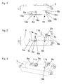
- Die Figur 1 zeigt das Gehäuse (3) einer Schalterbaugruppe mit zwei Knopfhalterelementen (4a, 4b) in einer Seitenansicht vor dem Zusammenfügen. Die Knopfhalterelemente (4a, 4b) bestehen jeweils aus einer ebenen Grundplatte (12a, 12b), die einstückig sich senkrecht zur Grundplattenebene erstreckende Anformungen (13a, 13b) aufweisen.
Diese Anformungen (13a, 13b) bestehen ihrerseits jeweils aus einem speziell geformten Abschnitt (5a, 5b), der über einen schmaleren Verbindungsabschnitt (14a, 14b) mit der Grundplatte (12a, 12b) verbunden ist. - Die Abschnitte (5a, 5b) werden, wie die Figuren 2 und 3 in zwei unterschiedlichen Ansichten zeigen, im nächsten Montageschritt durch jeweils eine Ausnehmung (6a, 6b) des Gehäuses (3) hindurchgeführt. Die Ausnehmungen (6a, 6b) sind als im wesentlichen schlitzförmige Durchbrüche ausgeführt, die jeweils mit einem an das Gehäuse (3) angeformten Kragen (11 a, 11 b) umrandet sind.
- Die Breite der Ausnehmungen (6a, 6b) ist jeweils über den größten Teil ihrer Länge geringer, als der Durchmesser des durch die Ausnehmung (6a, 6b) hindurchzuführenden Abschnitts (5a, 5b) des Knopfhalterelements (4a, 4b). Jede Ausnehmung (6a, 6b) weist jedoch einen verbreiterten Bereich (7a, 7b) auf, deren Kontur der Form des durch die Ausnehmung (6a, 6b) hindurchzuführenden Abschnitts (5a, 5b) des Knopfhalterelements (4a, 4b) angepaßt ist.
- So hat der Bereich (7b) der Ausnehmung (6b) die Form eines Langlochs (8b); der durch die Ausnehmung (6b) hindurchzuführende Abschnitt (5b) des zugehörigen Knopfhalterelements (4b) hat eine entsprechend angepaßte Querschnittsform, so daß der Abschnitt (5b) genau in diesem Bereich durch die Ausnehmung (6b) hindurchgeführt werden kann.
- Die Ausnehmung (6a) weist einem Bereich (7a) auf, in welchem die Ausnehmung (6a) mehrere sich senkrecht zu ihrer Längserstreckung erstreckende schlitzförmige Verbreiterungen aufweist. Die Kontur dieses Bereiches (7a) entspricht ebenfalls genau der Form des durch die Ausnehmung (6a) hindurchzuführenden Abschnitts (5a) des zugehörigen Knopfhalterelements, wobei die Form des Abschnitts (5a) hier durch mehrere miteinander verbundene Rippen (10) bestimmt wird.
- Die Abschnitte (5a, 5b) sind somit wie bei Schlüssel-Schloß-Paarungen in ihrer Form genau den verbreiterten Bereichen (7a, 7b) der Durchbrüche (6a, 6b) angepaßt, so daß jeder Abschnitt (5a, 5b) nur in dem ihm zugeordneten Bereich (7a, 7b) durch einen Durchbruch (6a, 6b) des Gehäuses (3) hindurchführbar ist und eine Verwechslung bei der Zuordnung von Knopfhalterelementen (4a, 4b) zu den Durchbrüchen (6a, 6b) bei der Montage ausgeschlossen ist.
- Im nächsten Montageschritt werden die Abschnitte (5a, 5b) ganz durch die Ausnehmungen (6a, 6b) des Gehäuses (3) hindurchgeführt und jeweils entlang des Kragens (11a, 11 b) in den mittleren Bereich der Ausnehmung (6a, 6b) verschoben. Hierdurch ergibt sich die in der Figur 4 dargestellte Anordnung.
- Die Knopfhalterelemente sind nun gegenüber dem Gehäuse (3) verriegelt, da sich die in der Figur 1 dargestellten schmalen Verbindungsabschnitte (14a, 14b) nun auf Höhe der Ausnehmungen (6a, 6b) und der Kragen (11a, 11 b) befinden und die breiteren Abschnitte (5a, 5b) der Anformungen (13a, 13b) sich auf den Kragen (11 a, 11 b) abstützen.
- Eine Trennung der so erreichten formschlüssigen Verbindungen zwischen dem Gehäuse (3) und den Knopfhalterelementen (4a, 4b) wäre in diesem Stadium der Montage noch dadurch möglich, daß die Abschnitte (5a, 5b) zu den verbreiterten Bereiche (7a, 7b) der Ausnehmungen (6a, 6b) zurückgeschoben werden.
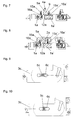
- Dies wird im nächsten Montageschritt, dargestellt in der Figur 5, durch die Anordnung von Schaltelementen (1 a, 1 a', 1 b, 1 b') innerhalb des Gehäuses (3) verhindert. Diese Schaltelemente (1 a, 1 a', 1 b, 1 b'), welche die elektrischen Funktionen des Schalters realisieren, sind im dargestellten Ausführungsbeispiel jeweils paarweise den Knopfhalterelementen (4a, 4b) zugeordnet, wobei die Schaltstößel (15a, 15a', 15b, 15b') der Schaltelemente (1 a, 1 a', 1 b, 1 b') beidseitig neben den Abschnitten (5a, 5b) der Knopfhalterelemente (4a, 4b) die Ausnehmungen (6a, 6b) durchragen.
- Die Montage der Schalterbaugruppe wird durch Verrasten eines Betätigungsknopfs (2a, 2b) mit jeweils einem Knopfhalterelement abgeschlossen (Figur 6).
- Die Figuren 7 und 8 verdeutlichen die in den Figuren 5 und 6 dargestellten Montagestadien nochmals anhand zweier Schnittzeichnungen. Beispielhaft soll hierzu die Anordnung, bestehend aus den Schaltelementen 1a und 1a', dem Knopfhalterelement 4a und dem Betätigungsknopf 2a näher erläutert werden.
- Wie aus den Figuren 7 und 8 hervorgeht, weist die Grundplatte (12a) des Knopfhalterelementes (4a) zwei Durchbrüche (16a, 16a') auf, durch die die Schaltstößel (15a, 15a') der Schaltelemente (1a, 1a') hindurchgeführt sind. Die Schaltstößel reichen weiterhin durch die Ausnehmung (6a) des Gehäuses (3) bis zum Betätigungsknopf (2a). Der Betätigungsknopf (2a) ist starr oder schwenkbar über ein Rastelement (9) mit dem Knopfhalterelement (4a) verbunden.
- Je nach Ausführung der Schaltelemente (1a, 1a') als Druck- oder Schiebeschalter ist, lösen die Schaltstößel (15a, 15a') entweder bei einer Krafteinwirkung in Richtung auf die Gehäuse der Schaltelemente (1a, 1a') oder bei einer Verschiebung parallel zur Ausnehmung (6a) eine Schaltfunktion aus. Auch eine Kombination beider Betätigungsarten kann vorgesehen sein. Eine Druckschaltfunktion wird dabei durch einen schwenkbar mit dem Knopfhalterelement (4a) verbundenen Betätigungsknopf (2a) realisiert, wobei bei einem Verschwenken des Betätigungsknopfes (2a) um eine Drehachse senkrecht zur Zeichnungsebene in der einen Drehrichtung der Schaltstößel 15a des Schaltelementes 1a und in der anderen Drehrichtung der Schaltstößel 15a' des Schaltelementes 1a' betätigt wird.
- Ein Schiebeschalterfunktion wird durch eine Verschiebung des Betätigungsknopfes (2a) parallel zur Gehäuseoberfläche erreicht. Das mit dem Betätigungsknopf (2a) verbundene Knopfhalterelement (4a) wirkt in diesem Fall als ein Schaltschieber, der die Verschiebung des Betätigungsknopfes (2a) entlang der Ausnehmung des Gehäuses ermöglicht und gegebenenfalls sogar durch Mitführen der in den Durchbrüchen (16a, 16a') des Knopfhalterelement (4a) angeordneten Schaltstößel die Schaltelemente (1a, 1a') direkt betätigt.
- Eine alternative Ausführungsform eines Schalters ist in den Figuren 9 und 10 dargestellt. Hierin ist der durch eine Ausnehmung (6c) des Gehäuses (3c) hindurchgeführte Abschnitt (5c) des Knopfhalterelementes derart ausgeführt, daß er in einer ersten Lage relativ zum Gehäuse (3c) durch die Ausnehmung hindurchgeführt werden kann (Figur 9) und sich in einer zweiten, relativ zur ersten Lage gedrehten Lage aufgrund seiner nun größeren Quererstreckung die Breite der Ausnehmung (6c) überragt und so das Knopfhalterelement mit dem Gehäuse (3c) verriegelt.
- Der Unterschied dieser Ausführungsform zur der zuvor diskutierten, liegt darin, daß hier die Verriegelung durch eine Drehung statt durch eine Verschiebung erreicht wird, wobei der Vorteil erzielt wird, daß die Ausnehmung (6c) keinen speziellen Bereich aufweisen muß, dessen Quererstreckung der Quererstreckung des Abschnitts (5c) im verriegelten Zustand entspricht.
-
- 1 a, 1a', 1b, 1b'
- Schaltelement
- 2a, 2b
- Betätigungsknopf
- 3, 3c
- Gehäuse
- 4a, 4b
- Knopfhalterelement
- 5a, 5b, 5c
- Abschnitt (des Knopfhalterelements)
- 6a, 6b, 6c
- Ausnehmung
- 7a, 7b
- Bereich (der Ausnehmung)
- 8a, 8b
- Langloch
- 9
- Rastelement
- 10
- Rippen
- 11a, 11 b
- Kragen
- 12a, 12b
- Grundplatte
- 13a, 13b
- Anformungen
- 14a, 14b
- Verbindungsabschnitte
- 15a, 15a'
- Schaltstößel
- 16a, 16a'
- Durchbrüche
Claims (16)
- Druck- oder Schiebeschalter oder kombinierter Druck- und Schiebeschalter für ein Kraftfahrzeug- mit mindestens einem Schaltelement (1a, 1a', 1b, 1 b'),- mit einem Betätigungsknopf (2a, 2b), über den mindestens eine Schaltfunktion des Schaltelements (1 a, 1a', 1 b, 1b') auslösbar ist,- mit einem Gehäuse (3, 3c), innerhalb dessen das Schaltelement (1a, 1a', 1 b, 1b') angeordnet ist und außerhalb dessen der Betätigungsknopf (2a, 2b) angeordnet ist,- und mit einem Knopfhalterelement (4a, 4b) zur Halterung des Betätigungsknopfs (2a, 2b), das mit dem Gehäuse (3, 3c) verbunden ist,dadurch gekennzeichnet,
daß ein Abschnitt (5a, 5b, 5c) des Knopfhalterelements (4a, 4b) durch eine Ausnehmung (6a, 6b, 6c) des Gehäuses (3, 3c) hindurchgeführt ist und daß das Knopfhalterelement (4a, 4b) durch eine Verschiebung oder Verdrehung relativ zum Gehäuse (3, 3c) mit dem Gehäuse (3, 3c) verriegelt ist. - Schalter nach Anspruch 1, dadurch gekennzeichnet, daß die Ausnehmung (6a, 6b) des Gehäuse (3) einen Bereich (7a, 7b) aufweist, dessen Form passend zur Form des durch die Ausnehmung (6a, 6b) hindurchgeführten Abschnitts (5a, 5b) des Knopfhalterelements (4a, 4b) ausgeführt ist.
- Schalter nach Anspruch 1, dadurch gekennzeichnet, daß die Ausnehmung (6c) des Gehäuses (3c) einen Bereich (7a, 7b) aufweist, dessen Form der Form des durch die Ausnehmung (6a, 6b) hindurchgeführten Abschnitts (5a, 5b) eines, bezogen auf die Ausrichtung eines montierten Knopfhalterelements (4a, 4b), gegenüber dem Gehäuse (3) gedrehten Knopfhalterelements (4a, 4b) entspricht.
- Schalter nach Anspruch 2 oder 3, dadurch gekennzeichnet, daß die Ausnehmung (6a, 6b) die Form eines Langlochs (8) aufweist.
- Schalter nach Anspruch 2 oder 3, dadurch gekennzeichnet, daß die Kontur des Bereiches (7a, 7b) der Ausnehmung (6a, 6b), entsprechend einer Schlüssel-Schloß-Paarung, genau oder zumindest weitgehend der Form des durch die Ausnehmung (6a, 6b) hindurchgeführten Abschnitts (5a, 5b) der Knopfhalterelement (4a, 4b) entspricht.
- Schalter nach Anspruch 1, dadurch gekennzeichnet, daß der durch die Ausnehmung (6a) hindurchgeführte Abschnitt (5a, 5c) mehrere miteinander verbundene Rippen (10) ausbildet.
- Schalter nach Anspruch 1, dadurch gekennzeichnet, daß der durch die Ausnehmung (6a, 6b) hindurchgeführte Abschnitt (5a, 5b) ein Rastelement (9) zur Verbindung des Abschnitt (5a, 5b) mit dem Betätigungsknopf (2a, 2b) aufweist.
- Schalter nach Anspruch 1, dadurch gekennzeichnet, daß das Gehäuse (3, 3c) entlang der Ausnehmung (6a, 6b, 6c) einen umlaufenden Kragen (11a, 11 b) aufweist.
- Schalter nach Anspruch 8, dadurch gekennzeichnet, daß der durch die Ausnehmung (6a, 6b, 6c) hindurchgeführte Abschnitt (5a, 5b, 5c) des Knopfhalterelements (4a, 4b) sich auf dem umlaufenden Kragen (11a, 11b) abstützt.
- Schalter nach Anspruch 9, dadurch gekennzeichnet, daß der durch die Ausnehmung (6a, 6b, 6c) hindurchgeführte Abschnitt (5a, 5b, 5c) des Knopfhalterelements (4a, 4b) auf dem umlaufenden Kragen (11a, 11 b) verschieblich ist.
- Schalter nach Anspruch 1, dadurch gekennzeichnet, daß der Schalter mehrere, vorzugsweise zwei, Schaltelemente (1 a, 1 a', 1 b, 1 b') aufweist.
- Schalter nach Anspruch 10 und 11, dadurch gekennzeichnet, daß die Schaltelemente (1 a, 1a', 1b, 1 b') zumindest jeweils eine Schiebeschaltfunktion realisieren und daß das Knopfhalterelement (4a, 4b) die Schiebebewegung des Betätigungsknopfes (2a, 2b) auf die Schaltelemente (1a, 1a', 1b, 1b') überträgt.
- Schalter nach Anspruch 8, dadurch gekennzeichnet, daß der Betätigungsknopf (2a, 2b) den umlaufenden Kragen (11a, 11 b) übergreift.
- Schalter nach Anspruch 1, dadurch gekennzeichnet, daß die Verriegelung zwischen dem Knopfhalterelement und dem Gehäuse spielfrei ausgeführt ist.
- Schalter nach Anspruch 1, dadurch gekennzeichnet, daß mehrere Schalter mittels einstückig verbundener Gehäuse (3, 3c) oder eines gemeinsamen Gehäuseträgers zu einer Schalterbaugruppe verbunden sind.
- Schalter nach Anspruch 1 oder 14, dadurch gekennzeichnet, daß die Schalter zur Steuerung der Position eines Fahrzeugsitzes oder eines Schiebedachs verwendet werden.
Applications Claiming Priority (1)
| Application Number | Priority Date | Filing Date | Title |
|---|---|---|---|
| DE102004058127A DE102004058127A1 (de) | 2004-12-02 | 2004-12-02 | Druck- oder Schiebeschalter oder kombinierter Druck- und Schiebeschalter für ein Kraftfahrzeug |
Publications (2)
| Publication Number | Publication Date |
|---|---|
| EP1667184A1 true EP1667184A1 (de) | 2006-06-07 |
| EP1667184B1 EP1667184B1 (de) | 2007-07-04 |
Family
ID=35520525
Family Applications (1)
| Application Number | Title | Priority Date | Filing Date |
|---|---|---|---|
| EP05026174A Expired - Lifetime EP1667184B1 (de) | 2004-12-02 | 2005-12-01 | Druck- oder Schiebeschalter oder kombinierter Druck- und Schiebeschalter für ein Kraftfahrzeug |
Country Status (4)
| Country | Link |
|---|---|
| EP (1) | EP1667184B1 (de) |
| AT (1) | ATE366459T1 (de) |
| DE (2) | DE102004058127A1 (de) |
| ES (1) | ES2288721T3 (de) |
Families Citing this family (1)
| Publication number | Priority date | Publication date | Assignee | Title |
|---|---|---|---|---|
| DE102007008909A1 (de) | 2007-02-23 | 2008-08-28 | Leopold Kostal Gmbh & Co. Kg | Schaltanordnung für ein Kraftfahrzeug |
Citations (2)
| Publication number | Priority date | Publication date | Assignee | Title |
|---|---|---|---|---|
| DE9208384U1 (de) * | 1992-06-23 | 1992-09-24 | Chen, Pao-Chin, Taipeh/T'ai-pei | Computertastenschalter |
| DE4327387A1 (de) * | 1993-08-14 | 1995-02-16 | Rafi Gmbh & Co | Halterung für elektrotechnische Bauelemente |
-
2004
- 2004-12-02 DE DE102004058127A patent/DE102004058127A1/de not_active Withdrawn
-
2005
- 2005-12-01 ES ES05026174T patent/ES2288721T3/es not_active Expired - Lifetime
- 2005-12-01 AT AT05026174T patent/ATE366459T1/de not_active IP Right Cessation
- 2005-12-01 EP EP05026174A patent/EP1667184B1/de not_active Expired - Lifetime
- 2005-12-01 DE DE502005000973T patent/DE502005000973D1/de not_active Expired - Lifetime
Patent Citations (2)
| Publication number | Priority date | Publication date | Assignee | Title |
|---|---|---|---|---|
| DE9208384U1 (de) * | 1992-06-23 | 1992-09-24 | Chen, Pao-Chin, Taipeh/T'ai-pei | Computertastenschalter |
| DE4327387A1 (de) * | 1993-08-14 | 1995-02-16 | Rafi Gmbh & Co | Halterung für elektrotechnische Bauelemente |
Also Published As
| Publication number | Publication date |
|---|---|
| ES2288721T3 (es) | 2008-01-16 |
| EP1667184B1 (de) | 2007-07-04 |
| ATE366459T1 (de) | 2007-07-15 |
| DE502005000973D1 (de) | 2007-08-16 |
| DE102004058127A1 (de) | 2006-06-14 |
Similar Documents
| Publication | Publication Date | Title |
|---|---|---|
| DE19919335B4 (de) | Vorrichtung zur lösbaren Verriegelung einer Kopfstütze | |
| EP1848903B1 (de) | Elektrische schalteinrichtung für ein kraftfahrzeug | |
| EP2188148B1 (de) | Verstelleinrichtung zur längsverstellung einer kraftfahrzeugkomponente | |
| DE102015219472B4 (de) | Längsverstellvorrichtung für einen Fahrzeugsitz, Schienenpaar und Fahrzeugsitz | |
| DE102016110340B3 (de) | Anordnung zum zeitweisen Vorspannen einer Teleskopgabel | |
| EP1451490B1 (de) | Schaltknauf | |
| EP1971503A1 (de) | Schalter, insbesondere lenkstockschalter für kraftfahrzeuge | |
| WO2019238172A1 (de) | SCHLIEßVORRICHTUNG FÜR EIN KRAFTFAHRZEUG | |
| EP1667184B1 (de) | Druck- oder Schiebeschalter oder kombinierter Druck- und Schiebeschalter für ein Kraftfahrzeug | |
| EP3754680B1 (de) | Schaltervorrichtung für ein gargerät mit einem durch eine tür verschliessbaren garraum und gargerät | |
| WO2015124129A1 (de) | Schaltanordnung für ein getriebe | |
| EP1251418B1 (de) | Arretiervorrichtung für zueinander bewegliche Maschinenteile | |
| EP2350500B1 (de) | Schaltvorrichtung für ein schaltgetriebe eines kraftfahrzeugs | |
| EP1385076B1 (de) | Drehschaltervorrichtung | |
| EP2055529B1 (de) | Schaltvorrichtung | |
| EP1139194B1 (de) | Wegeventil mit mechanischer Betätigungseinrichtung | |
| EP0647954B1 (de) | Drehantrieb | |
| DE102004032335B4 (de) | Elektrischer Schalter und Schalteranordnung | |
| DE879564C (de) | Schalter mit dreh-, kipp- oder verschiebbarem Schaltglied | |
| AT401123B (de) | Handbetätigter schalter mit einer verriegelung | |
| DE10261831A1 (de) | Aufprallweiches Betätigungselement zur Anordnung in einem Fahrzeug | |
| EP2135270B1 (de) | Schalteranordnung für ein kraftfahrzeug | |
| EP2504850B1 (de) | Elektrischer schalter | |
| DE102005018144B4 (de) | Elektrische Schalteranordnung | |
| EP1859986B1 (de) | Schalteranordnung, insbesondere zur Verstellung eines Fahrzeugsitzes |
Legal Events
| Date | Code | Title | Description |
|---|---|---|---|
| PUAI | Public reference made under article 153(3) epc to a published international application that has entered the european phase |
Free format text: ORIGINAL CODE: 0009012 |
|
| 17P | Request for examination filed |
Effective date: 20060227 |
|
| AK | Designated contracting states |
Kind code of ref document: A1 Designated state(s): AT BE BG CH CY CZ DE DK EE ES FI FR GB GR HU IE IS IT LI LT LU LV MC NL PL PT RO SE SI SK TR |
|
| AX | Request for extension of the european patent |
Extension state: AL BA HR MK YU |
|
| 17Q | First examination report despatched |
Effective date: 20060914 |
|
| AKX | Designation fees paid |
Designated state(s): AT BE BG CH CY CZ DE DK EE ES FI FR GB GR HU IE IS IT LI LT LU LV MC NL PL PT RO SE SI SK TR |
|
| GRAP | Despatch of communication of intention to grant a patent |
Free format text: ORIGINAL CODE: EPIDOSNIGR1 |
|
| GRAS | Grant fee paid |
Free format text: ORIGINAL CODE: EPIDOSNIGR3 |
|
| GRAA | (expected) grant |
Free format text: ORIGINAL CODE: 0009210 |
|
| AK | Designated contracting states |
Kind code of ref document: B1 Designated state(s): AT BE BG CH CY CZ DE DK EE ES FI FR GB GR HU IE IS IT LI LT LU LV MC NL PL PT RO SE SI SK TR |
|
| REG | Reference to a national code |
Ref country code: GB Ref legal event code: FG4D Free format text: NOT ENGLISH |
|
| REG | Reference to a national code |
Ref country code: CH Ref legal event code: EP |
|
| REG | Reference to a national code |
Ref country code: IE Ref legal event code: FG4D Free format text: LANGUAGE OF EP DOCUMENT: GERMAN |
|
| REF | Corresponds to: |
Ref document number: 502005000973 Country of ref document: DE Date of ref document: 20070816 Kind code of ref document: P |
|
| GBT | Gb: translation of ep patent filed (gb section 77(6)(a)/1977) |
Effective date: 20070822 |
|
| ET | Fr: translation filed | ||
| NLV1 | Nl: lapsed or annulled due to failure to fulfill the requirements of art. 29p and 29m of the patents act | ||
| REG | Reference to a national code |
Ref country code: ES Ref legal event code: FG2A Ref document number: 2288721 Country of ref document: ES Kind code of ref document: T3 |
|
| PG25 | Lapsed in a contracting state [announced via postgrant information from national office to epo] |
Ref country code: LT Free format text: LAPSE BECAUSE OF FAILURE TO SUBMIT A TRANSLATION OF THE DESCRIPTION OR TO PAY THE FEE WITHIN THE PRESCRIBED TIME-LIMIT Effective date: 20070704 Ref country code: FI Free format text: LAPSE BECAUSE OF FAILURE TO SUBMIT A TRANSLATION OF THE DESCRIPTION OR TO PAY THE FEE WITHIN THE PRESCRIBED TIME-LIMIT Effective date: 20070704 Ref country code: BG Free format text: LAPSE BECAUSE OF FAILURE TO SUBMIT A TRANSLATION OF THE DESCRIPTION OR TO PAY THE FEE WITHIN THE PRESCRIBED TIME-LIMIT Effective date: 20071004 Ref country code: SI Free format text: LAPSE BECAUSE OF FAILURE TO SUBMIT A TRANSLATION OF THE DESCRIPTION OR TO PAY THE FEE WITHIN THE PRESCRIBED TIME-LIMIT Effective date: 20070704 Ref country code: IS Free format text: LAPSE BECAUSE OF FAILURE TO SUBMIT A TRANSLATION OF THE DESCRIPTION OR TO PAY THE FEE WITHIN THE PRESCRIBED TIME-LIMIT Effective date: 20071104 Ref country code: PT Free format text: LAPSE BECAUSE OF FAILURE TO SUBMIT A TRANSLATION OF THE DESCRIPTION OR TO PAY THE FEE WITHIN THE PRESCRIBED TIME-LIMIT Effective date: 20071204 Ref country code: NL Free format text: LAPSE BECAUSE OF FAILURE TO SUBMIT A TRANSLATION OF THE DESCRIPTION OR TO PAY THE FEE WITHIN THE PRESCRIBED TIME-LIMIT Effective date: 20070704 |
|
| PG25 | Lapsed in a contracting state [announced via postgrant information from national office to epo] |
Ref country code: PL Free format text: LAPSE BECAUSE OF FAILURE TO SUBMIT A TRANSLATION OF THE DESCRIPTION OR TO PAY THE FEE WITHIN THE PRESCRIBED TIME-LIMIT Effective date: 20070704 |
|
| REG | Reference to a national code |
Ref country code: IE Ref legal event code: FD4D |
|
| PG25 | Lapsed in a contracting state [announced via postgrant information from national office to epo] |
Ref country code: LV Free format text: LAPSE BECAUSE OF FAILURE TO SUBMIT A TRANSLATION OF THE DESCRIPTION OR TO PAY THE FEE WITHIN THE PRESCRIBED TIME-LIMIT Effective date: 20070704 |
|
| PG25 | Lapsed in a contracting state [announced via postgrant information from national office to epo] |
Ref country code: GR Free format text: LAPSE BECAUSE OF FAILURE TO SUBMIT A TRANSLATION OF THE DESCRIPTION OR TO PAY THE FEE WITHIN THE PRESCRIBED TIME-LIMIT Effective date: 20071005 Ref country code: DK Free format text: LAPSE BECAUSE OF FAILURE TO SUBMIT A TRANSLATION OF THE DESCRIPTION OR TO PAY THE FEE WITHIN THE PRESCRIBED TIME-LIMIT Effective date: 20070704 |
|
| PLBE | No opposition filed within time limit |
Free format text: ORIGINAL CODE: 0009261 |
|
| STAA | Information on the status of an ep patent application or granted ep patent |
Free format text: STATUS: NO OPPOSITION FILED WITHIN TIME LIMIT |
|
| PG25 | Lapsed in a contracting state [announced via postgrant information from national office to epo] |
Ref country code: SK Free format text: LAPSE BECAUSE OF FAILURE TO SUBMIT A TRANSLATION OF THE DESCRIPTION OR TO PAY THE FEE WITHIN THE PRESCRIBED TIME-LIMIT Effective date: 20070704 Ref country code: IE Free format text: LAPSE BECAUSE OF FAILURE TO SUBMIT A TRANSLATION OF THE DESCRIPTION OR TO PAY THE FEE WITHIN THE PRESCRIBED TIME-LIMIT Effective date: 20070704 |
|
| 26N | No opposition filed |
Effective date: 20080407 |
|
| BERE | Be: lapsed |
Owner name: LEOPOLD KOSTAL G.M.B.H. & CO. KG Effective date: 20071231 |
|
| PG25 | Lapsed in a contracting state [announced via postgrant information from national office to epo] |
Ref country code: RO Free format text: LAPSE BECAUSE OF FAILURE TO SUBMIT A TRANSLATION OF THE DESCRIPTION OR TO PAY THE FEE WITHIN THE PRESCRIBED TIME-LIMIT Effective date: 20070704 Ref country code: SE Free format text: LAPSE BECAUSE OF FAILURE TO SUBMIT A TRANSLATION OF THE DESCRIPTION OR TO PAY THE FEE WITHIN THE PRESCRIBED TIME-LIMIT Effective date: 20071004 |
|
| PG25 | Lapsed in a contracting state [announced via postgrant information from national office to epo] |
Ref country code: MC Free format text: LAPSE BECAUSE OF NON-PAYMENT OF DUE FEES Effective date: 20071231 |
|
| PG25 | Lapsed in a contracting state [announced via postgrant information from national office to epo] |
Ref country code: BE Free format text: LAPSE BECAUSE OF NON-PAYMENT OF DUE FEES Effective date: 20071231 |
|
| PG25 | Lapsed in a contracting state [announced via postgrant information from national office to epo] |
Ref country code: EE Free format text: LAPSE BECAUSE OF FAILURE TO SUBMIT A TRANSLATION OF THE DESCRIPTION OR TO PAY THE FEE WITHIN THE PRESCRIBED TIME-LIMIT Effective date: 20070704 |
|
| PG25 | Lapsed in a contracting state [announced via postgrant information from national office to epo] |
Ref country code: AT Free format text: LAPSE BECAUSE OF NON-PAYMENT OF DUE FEES Effective date: 20071201 |
|
| PG25 | Lapsed in a contracting state [announced via postgrant information from national office to epo] |
Ref country code: CY Free format text: LAPSE BECAUSE OF FAILURE TO SUBMIT A TRANSLATION OF THE DESCRIPTION OR TO PAY THE FEE WITHIN THE PRESCRIBED TIME-LIMIT Effective date: 20070704 |
|
| PG25 | Lapsed in a contracting state [announced via postgrant information from national office to epo] |
Ref country code: LU Free format text: LAPSE BECAUSE OF NON-PAYMENT OF DUE FEES Effective date: 20071201 |
|
| PG25 | Lapsed in a contracting state [announced via postgrant information from national office to epo] |
Ref country code: HU Free format text: LAPSE BECAUSE OF FAILURE TO SUBMIT A TRANSLATION OF THE DESCRIPTION OR TO PAY THE FEE WITHIN THE PRESCRIBED TIME-LIMIT Effective date: 20080105 Ref country code: TR Free format text: LAPSE BECAUSE OF FAILURE TO SUBMIT A TRANSLATION OF THE DESCRIPTION OR TO PAY THE FEE WITHIN THE PRESCRIBED TIME-LIMIT Effective date: 20070704 |
|
| REG | Reference to a national code |
Ref country code: CH Ref legal event code: PL |
|
| PG25 | Lapsed in a contracting state [announced via postgrant information from national office to epo] |
Ref country code: LI Free format text: LAPSE BECAUSE OF NON-PAYMENT OF DUE FEES Effective date: 20091231 Ref country code: CH Free format text: LAPSE BECAUSE OF NON-PAYMENT OF DUE FEES Effective date: 20091231 |
|
| REG | Reference to a national code |
Ref country code: FR Ref legal event code: PLFP Year of fee payment: 11 |
|
| REG | Reference to a national code |
Ref country code: FR Ref legal event code: PLFP Year of fee payment: 12 |
|
| REG | Reference to a national code |
Ref country code: FR Ref legal event code: PLFP Year of fee payment: 13 |
|
| REG | Reference to a national code |
Ref country code: DE Ref legal event code: R084 Ref document number: 502005000973 Country of ref document: DE |
|
| REG | Reference to a national code |
Ref country code: DE Ref legal event code: R081 Ref document number: 502005000973 Country of ref document: DE Owner name: KOSTAL AUTOMOBIL ELEKTRIK GMBH & CO. KG, DE Free format text: FORMER OWNER: LEOPOLD KOSTAL GMBH & CO. KG, 58513 LUEDENSCHEID, DE |
|
| PGFP | Annual fee paid to national office [announced via postgrant information from national office to epo] |
Ref country code: CZ Payment date: 20210927 Year of fee payment: 17 |
|
| PGFP | Annual fee paid to national office [announced via postgrant information from national office to epo] |
Ref country code: FR Payment date: 20211223 Year of fee payment: 17 Ref country code: GB Payment date: 20211111 Year of fee payment: 17 Ref country code: DE Payment date: 20211214 Year of fee payment: 17 |
|
| PGFP | Annual fee paid to national office [announced via postgrant information from national office to epo] |
Ref country code: IT Payment date: 20211115 Year of fee payment: 17 |
|
| PGFP | Annual fee paid to national office [announced via postgrant information from national office to epo] |
Ref country code: ES Payment date: 20220114 Year of fee payment: 17 |
|
| REG | Reference to a national code |
Ref country code: DE Ref legal event code: R119 Ref document number: 502005000973 Country of ref document: DE |
|
| PG25 | Lapsed in a contracting state [announced via postgrant information from national office to epo] |
Ref country code: CZ Free format text: LAPSE BECAUSE OF NON-PAYMENT OF DUE FEES Effective date: 20221201 |
|
| GBPC | Gb: european patent ceased through non-payment of renewal fee |
Effective date: 20221201 |
|
| PG25 | Lapsed in a contracting state [announced via postgrant information from national office to epo] |
Ref country code: GB Free format text: LAPSE BECAUSE OF NON-PAYMENT OF DUE FEES Effective date: 20221201 Ref country code: DE Free format text: LAPSE BECAUSE OF NON-PAYMENT OF DUE FEES Effective date: 20230701 |
|
| PG25 | Lapsed in a contracting state [announced via postgrant information from national office to epo] |
Ref country code: FR Free format text: LAPSE BECAUSE OF NON-PAYMENT OF DUE FEES Effective date: 20221231 |
|
| REG | Reference to a national code |
Ref country code: ES Ref legal event code: FD2A Effective date: 20240126 |
|
| PG25 | Lapsed in a contracting state [announced via postgrant information from national office to epo] |
Ref country code: IT Free format text: LAPSE BECAUSE OF NON-PAYMENT OF DUE FEES Effective date: 20221201 |
|
| PG25 | Lapsed in a contracting state [announced via postgrant information from national office to epo] |
Ref country code: ES Free format text: LAPSE BECAUSE OF NON-PAYMENT OF DUE FEES Effective date: 20221202 |
|
| PG25 | Lapsed in a contracting state [announced via postgrant information from national office to epo] |
Ref country code: ES Free format text: LAPSE BECAUSE OF NON-PAYMENT OF DUE FEES Effective date: 20221202 |