EP1664665B1 - Induktive geschoss-schnittstelle für die gleichzeitige übertragung von daten und energie - Google Patents
Induktive geschoss-schnittstelle für die gleichzeitige übertragung von daten und energie Download PDFInfo
- Publication number
- EP1664665B1 EP1664665B1 EP04821604A EP04821604A EP1664665B1 EP 1664665 B1 EP1664665 B1 EP 1664665B1 EP 04821604 A EP04821604 A EP 04821604A EP 04821604 A EP04821604 A EP 04821604A EP 1664665 B1 EP1664665 B1 EP 1664665B1
- Authority
- EP
- European Patent Office
- Prior art keywords
- projectile
- data
- magnetic core
- coil
- setter
- Prior art date
- Legal status (The legal status is an assumption and is not a legal conclusion. Google has not performed a legal analysis and makes no representation as to the accuracy of the status listed.)
- Expired - Lifetime
Links
- 230000001939 inductive effect Effects 0.000 title claims description 28
- 229910000859 α-Fe Inorganic materials 0.000 claims description 22
- 239000000463 material Substances 0.000 claims description 19
- 239000004033 plastic Substances 0.000 claims description 9
- 229920003023 plastic Polymers 0.000 claims description 9
- 229910001289 Manganese-zinc ferrite Inorganic materials 0.000 claims description 7
- 229910001053 Nickel-zinc ferrite Inorganic materials 0.000 claims description 7
- JIYIUPFAJUGHNL-UHFFFAOYSA-N [O--].[O--].[O--].[O--].[O--].[O--].[O--].[O--].[O--].[O--].[O--].[O--].[O--].[O--].[O--].[O--].[O--].[O--].[O--].[O--].[Mn++].[Mn++].[Mn++].[Fe+3].[Fe+3].[Fe+3].[Fe+3].[Fe+3].[Fe+3].[Fe+3].[Fe+3].[Fe+3].[Fe+3].[Zn++].[Zn++] Chemical compound [O--].[O--].[O--].[O--].[O--].[O--].[O--].[O--].[O--].[O--].[O--].[O--].[O--].[O--].[O--].[O--].[O--].[O--].[O--].[O--].[Mn++].[Mn++].[Mn++].[Fe+3].[Fe+3].[Fe+3].[Fe+3].[Fe+3].[Fe+3].[Fe+3].[Fe+3].[Fe+3].[Fe+3].[Zn++].[Zn++] JIYIUPFAJUGHNL-UHFFFAOYSA-N 0.000 claims description 6
- 229920001778 nylon Polymers 0.000 claims description 6
- 239000004677 Nylon Substances 0.000 claims description 5
- 150000001875 compounds Chemical class 0.000 claims description 2
- 239000011162 core material Substances 0.000 description 53
- XEEYBQQBJWHFJM-UHFFFAOYSA-N Iron Chemical compound [Fe] XEEYBQQBJWHFJM-UHFFFAOYSA-N 0.000 description 17
- 238000010586 diagram Methods 0.000 description 10
- 230000008878 coupling Effects 0.000 description 8
- 238000010168 coupling process Methods 0.000 description 8
- 238000005859 coupling reaction Methods 0.000 description 8
- 229910052742 iron Inorganic materials 0.000 description 8
- 230000004907 flux Effects 0.000 description 5
- 239000003990 capacitor Substances 0.000 description 4
- 239000002245 particle Substances 0.000 description 4
- 230000035699 permeability Effects 0.000 description 4
- 239000012876 carrier material Substances 0.000 description 3
- 238000003754 machining Methods 0.000 description 3
- 239000012141 concentrate Substances 0.000 description 2
- 230000001276 controlling effect Effects 0.000 description 2
- 239000000839 emulsion Substances 0.000 description 2
- 238000001125 extrusion Methods 0.000 description 2
- 239000003562 lightweight material Substances 0.000 description 2
- WJZHMLNIAZSFDO-UHFFFAOYSA-N manganese zinc Chemical compound [Mn].[Zn] WJZHMLNIAZSFDO-UHFFFAOYSA-N 0.000 description 2
- 238000004519 manufacturing process Methods 0.000 description 2
- 238000012986 modification Methods 0.000 description 2
- 230000004048 modification Effects 0.000 description 2
- 238000000465 moulding Methods 0.000 description 2
- 239000002994 raw material Substances 0.000 description 2
- 241000251729 Elasmobranchii Species 0.000 description 1
- 235000015842 Hesperis Nutrition 0.000 description 1
- 235000012633 Iberis amara Nutrition 0.000 description 1
- 229920000106 Liquid crystal polymer Polymers 0.000 description 1
- 239000004977 Liquid-crystal polymers (LCPs) Substances 0.000 description 1
- 229920000265 Polyparaphenylene Polymers 0.000 description 1
- 229910001308 Zinc ferrite Inorganic materials 0.000 description 1
- XAGFODPZIPBFFR-UHFFFAOYSA-N aluminium Chemical compound [Al] XAGFODPZIPBFFR-UHFFFAOYSA-N 0.000 description 1
- 229910052782 aluminium Inorganic materials 0.000 description 1
- 238000004891 communication Methods 0.000 description 1
- 238000005336 cracking Methods 0.000 description 1
- 238000013524 data verification Methods 0.000 description 1
- 238000005474 detonation Methods 0.000 description 1
- 230000005670 electromagnetic radiation Effects 0.000 description 1
- 239000002360 explosive Substances 0.000 description 1
- 230000008018 melting Effects 0.000 description 1
- 238000002844 melting Methods 0.000 description 1
- 239000008188 pellet Substances 0.000 description 1
- 239000004417 polycarbonate Substances 0.000 description 1
- 229920000515 polycarbonate Polymers 0.000 description 1
- -1 polyphenylen Polymers 0.000 description 1
- 230000001681 protective effect Effects 0.000 description 1
- 230000001105 regulatory effect Effects 0.000 description 1
- 229920005989 resin Polymers 0.000 description 1
- 239000011347 resin Substances 0.000 description 1
- 230000004044 response Effects 0.000 description 1
- 238000003860 storage Methods 0.000 description 1
- 229920001169 thermoplastic Polymers 0.000 description 1
- 239000004416 thermosoftening plastic Substances 0.000 description 1
- 238000004804 winding Methods 0.000 description 1
Images




Classifications
-
- F—MECHANICAL ENGINEERING; LIGHTING; HEATING; WEAPONS; BLASTING
- F42—AMMUNITION; BLASTING
- F42C—AMMUNITION FUZES; ARMING OR SAFETY MEANS THEREFOR
- F42C17/00—Fuze-setting apparatus
- F42C17/04—Fuze-setting apparatus for electric fuzes
Definitions
- the present invention relates generally to projectiles. More specifically, the present invention relates to an inductive interface for transferring data and power to and/or from a projectile.
- Inductive fuze setters for projectiles are known in the art. Inductive fuze setters are used to transmit data to a projectile, such as time-of-flight data, time-to-burst data, target coordinates, etc., as is known in the art. It is very important to be able to quickly and reliably transmit data to a projectile as, for example, the projectile is moving from a magazine to a cannon. Moreover, it is important to be able to verify that the projectile has correctly received the transmitted data.
- the projectile includes an internal coil for forming an inductive interface with an external setter device.
- the setter device includes a coil which, when placed in close proximity to the coil within the projectile, becomes inductively coupled to the projectile coil.
- the setter coil is excited and modulated to communicate data to the projectile.
- the projectile coil receives the data which can then be provided to appropriate electronic circuitry included within the projectile as is known.
- the electronic circuitry within the projectile may excite and modulate the projectile coil and thereby inductively transmit data to the setter coil.
- a magnetic core within the projectile.
- the projectile coil is wound around the magnetic core in order to concentrate the magnetic flux and increase coupling.
- the magnetic core may be made of iron or typical ferrite core material.
- iron is relatively heavy and can thereby detract from the projectile capacity.
- Typical ferrite core material may be slightly lighter in weight compared to iron.
- ferrite core material is typically very brittle, not easily machinable, and subject to cracking and/or otherwise losing its structural integrity during handling and/or use of the projectile.
- U.S. 6,268,785 which forms a basis for the preamble of independent claim 1, discloses a target system having a power coil for transferring power, and a separate data coil for transferring data.
- the present invention provides a projectile including an inductive interface as recited in the claims.
- the interface includes a high-permeability magnetic core which maximizes power and data transfer while reducing the emission of electromagnetic radiation. This reduces interference with other electronics and reduces the probability of sensitive data being intercepted by a third party.
- the core is made of a relatively lightweight material with high impact strength, such as manganese-zinc ornickel-zinc ferrite filled plastic.
- the core does not tend to crack, etc., as do typical magnetic cores of scintered ferrite material or the like.
- the core is lightweight compared to iron or conventional ferrite cores, thus providing significant weight savings.
- the core can be easily manufactured in complex shapes and sizes via molding, extrusion, machining, etc. This results in significantly lower manufacturing costs as will be appreciated.
- the inductive interface may include a single set of coils (setter coil and projectile coil (also referred to herein as a target coil). Data can be transferred into the multiplexing the power waveform with the data waveform (which may be modulated with any convenient modulation scheme).
- a projectile includes a body, a payload within the body, a target system within the body for affecting operation of the projectile, and an inductive interface which, as part of the target system, permits transfer of power and data between the target system and an external setter system.
- the inductive interface includes a magnetic core comprised of a compound of ferrite material and non-ferrite material and a same coil wrapped around the magnetic core.
- the fuze setter system 20 includes a projectile 22 and an external setter system 24.
- the fuze setter system 20 provides a means by which data, such as time-of-flight data, time-to-burst data, target coordinates, etc., or any other types of data which affect the operation of the projectile 22, can be exchanged between the setter system 24 and the projectile 22.
- the fuze setter system 20 provides a means by which power may be delivered to the projectile 22 in order to provide operational power within the projectile 22.
- the projectile 22 may be any type of projectile including, but not limited to, artillery shells, missiles, rockets, bombs, torpedoes, etc..
- the projectile 22 may be powered or unpowered.
- the projectile 22 may travel at any velocity such as subsonic, sonic or hypersonic, or a combination thereof.
- the projectile 22 may be single stage or multi-stage.
- the projectile 22 includes a body 23, at least a portion of which is projected at time of launch.
- the body 23 is typically cylindrical, but is not limited to such a shape as will be appreciated.
- the body 23 may be a single integral unit, or part of a multi-stage or multi-component vehicle.
- the body 23 may be a shell launched by artillery, or a multi-stage rocket in which portions of the body serve as a carrier vehicle for the warhead, etc.
- the present invention contemplates any and all such types of projectiles.
- the projectile 22 further includes a payload 26 which is shown in phantom in Fig. 1 .
- the payload 26 is carried in the body 23 and can be any conventional or nonconventional type of payload as will be appreciated by those having ordinary skill in the art.
- the payload 26 may include explosives, conventional or nuclear warhead, guidance system, communication system, kill vehicle, satellite, etc.
- the payload 26 may be the mass of the body 23 itself, for example.
- the projectile 22 includes aerodynamic fins 28. It will be appreciated, however, that such fins 28 are not necessary within the scope of the invention.
- the exemplary projectile body 23 includes a nose portion 30 at the forward end of the body 23.
- the projectile 22 includes a target coil 32 (shown in phantom) within the nose portion 30. It will be appreciated, however, that the target coil 32 could be located within a different portion of the body 23 without departing from the scope of the invention.
- the target coil 32 is electrically coupled to target electronics 34 (shown in phantom) within the body 23.
- the target coil 32 and target electronics 34 make up what is referred to herein as the target system 36 of the projectile 22.
- the target coil 32 provides a means by which the setter system 24 may be inductively coupled to the target electronics 34 to transfer data, such as time-of-flight data, time-to-burst data, target coordinates, etc., or any other types of data which affect the operation of the projectile 22.
- data such as time-of-flight data, time-to-burst data, target coordinates, etc., or any other types of data which affect the operation of the projectile 22.
- power may be delivered to the projectile 22 in order to provide operational power within the projectile 22.
- the setter system 24 includes a setter coil 38 (shown in phantom) located within a nose portion adapter 40.
- the nose portion adapter 40 is designed to engage the nose portion 30 of the projectile 22 in such a manner as to place the setter coil 38 in close proximity to the target coil 32 to allow for inductive coupling therebetween.
- the nose portion adapter 40 includes a conical shaped cavity 42 into which the nose portion 30 is inserted to conduct data and/or power transfer.
- the setter coil 38 which is placed about the circumference of the cavity 42, is engaged in close proximity to the target coil 32, which is placed about the circumference of the nose portion 30.
- the setter coil 38 is electrically coupled to the setter electronics 44 included as part of the setter system 24.
- the setter electronics 44 and the target electronics 32 are designed to communicate with each other via an inductive interface formed by the target coil 32 and the setter coil 38.
- the nose portion 30 is inserted into the nose portion adapter 40 and operational data and/or power is inductively coupled between the setter electronics 44 and the target electronics 34.
- the projectile 22 may thereafter be launched in accordance with the operational data and/or power thus provided.
- the setter system 24 includes the setter electronics 44 and the setter coil 38.
- the setter electronics 44 includes a power driver 50 for delivering power to the target system 36 inductively via the setter coil 38.
- the setter electronics 44 includes a data driver 52 for providing operational data to the target system 36. Again, such data is provided inductively via the setter coil 38.
- a data receiver 54 for receiving data from the target system 36 in an embodiment in which the target system 36 communicates back to the setter system 24. For example, the target system 36 may transmit status information or data verification to the setter system 24.
- the setter electronics 44 further includes control logic 56 for controlling the various operations within the setter system 24 as will be appreciated by those skilled in the art. Moreover, the setter electronics 44 includes a power supply 58 for providing operating power to the setter system 24 as will also be appreciated by those skilled in the art.
- the target system 36 includes the target coil 32 and the target electronics 34.
- the target electronics 34 includes a power receiver 60 for receiving power inductively coupled from the power driver 50 via the target coil 32.
- the target electronics 34 includes a data receiver 62 for receiving data inductively coupled from the data driver 52 via the target coil 32.
- the target electronics 34 also includes a data driver 64 for providing response data to the setter system 24 via the target coil 32 in an embodiment which desires such data transfer. In another embodiment which does not require the target system 36 to communicate back to the setter system 24, the data driver 64 may be omitted as will be appreciated.
- the target system 36 further includes control logic 66 for controlling the operation within the target system 36 as will also be appreciated by those having ordinary skill in the art.
- the power driver 50 and power receiver 60 enable the setter system 24 to deliver operating power inductively to the target system 36.
- the power driver 50 and power receiver 60 may be omitted.
- the data driver 52 and data receiver 62 may be omitted as will be appreciated.
- the setter system 24 and the target system 36 each include only a single coil 38 and 32, respectively. In another embodiment in which it is not preferable to utilize a single coil in each respective system, multiple coils may be utilized.
- the setter system 24 and target system 36 may each include a pair of coils, one coil used for transferring data and another coil used for transferring power.
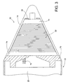
- the inductive interface formed by the target coil 32 within the projectile 22 is illustrated in relevant cross section.
- the target coil 32 is located within the nose portion 30 of the projectile 22 in accordance with the exemplary embodiment.
- an annular base 70 formed of machined aluminum or the like is provided at the forward end of the projectile 22 and serves as the base of the nose portion 30.
- the base 70 is bolted, welded, or otherwise secured to a cylindrical housing portion of the body 23.
- the base 70 includes a lip 72 about its outer circumference, and seated against the lip 72 is a magnetic core 74 in accordance with an aspect of the invention.
- the magnetic core 74 has a hollow conical shape.
- the base of the hollow cone shaped magnetic core 74 is seated against the lip 72.
- the target coil 32 comprises an electrical winding wound about the outer surface of the magnetic core 74 and coupled to the target electronics (not shown) within the body 23 via wires 76.
- Fig. 3 illustrates the coil 32 and magnetic core 74 in non-cross-section
- Fig. 4 illustrates the coil 32 and magnetic core 74 in cross-section as will be appreciated.
- a radome 78 having a hollow conical shape conforming to that of the magnetic core 74 forms a cover which fits over the magnetic core 74 and coil 32.
- the radome 78 may be formed of conventional radome material such as plastic, etc.
- the radome 78 serves as a protective cover to the target coil 32 as well as any other interior equipment or electronics (e.g., seeker antenna, lens array, etc.).
- the radome 78 permits the transfer of electromagnetic energy therethrough, be it radar signals from within the projectile 22, or inductive energy between the target coil 32 and the setter coil 38.
- the radome 78 includes a central cylindrical portion 80 having a diameter which may be inserted through a central opening at the top of the magnetic core 74.
- the central cylindrical portion 80 is hollow and includes protrusions 82 at the open end of the radome 78.
- the central cylindrical portion 80 includes axial slots 84 which permit the cylindrical portion 80 to collapse elastically so that the protrusions 82 may be snap fit into an aperture 86 within the base 70.
- a spring washer 88 is placed between a face 90 of the radome 78 and a face 92 of the magnetic core 74.
- the spring washer 88 prevents axial movement, whereas the central cylindrical portion 80 prevents radial movement.
- the magnetic core 74, target coil 32 and radome 78 may be assembled as part of the body 23 with a simple snap fit.
- the magnetic core 74 in accordance with one aspect of the present invention is not simply an iron core or scintered ferrite core. Rather, the magnetic core 74 is made of a lightweight material, such as manganese-zinc or nickel-zinc ferrite filled plastic. The magnetic core 74 has high impact strength and therefore does not tend to crack, etc. as do typical magnetic cores of scintered ferrite material or the like. Moreover, the magnetic core 74 is lightweight compared to iron or conventional ferrite cores, thus providing significant weight savings. Furthermore, the core can be easily manufactured in complex shapes and sizes via molding, extrusion, machining, etc. This results in significantly lower manufacturing costs as will be appreciated.
- particles of high magnetic permeability material such as manganese-zinc ferrite or nickel-zinc ferrite are combined with a carrier material(s) such as Nylon No. 6.
- the carrier material may not have as high a magnetic permeability as manganese-zinc ferrite or nickel-zinc ferrite, but is significantly easier to machine, mold, extrude, etc.
- the magnetic core 74 is much more easily manufactured.
- the magnetic core 74 is significantly less brittle than a scintered core and far less likely to incur damage due to vibration, etc.
- the magnetic core 74 is significantly lighter in weight than an iron or scintered ferrite core.
- particles of manganese-zinc ferrite or nickel-zinc ferrite are combined with Nylon No. 6 stock.
- the combination is heated to a temperature exceeding the melting point of the Nylon No. 6 and stirred, thus creating an emulsion of suspended manganese-zinc ferrite or nickel-zinc ferrite particles within the plastic carrier medium.
- the emulsion may then be extruded and chopped to form the raw material (e.g., pellets).
- the raw material may be subsequently molded, machined, etc. in order to form the particular shape of the magnetic core 74.
- the ferrite particles remain impregnated within the Nylon, and serve to concentrate the magnetic flux lines induced therein via the target coil 32.
- ferrite materials other than manganese-zinc ferrite or nickel-zinc ferrite may be used.
- other carrier materials such as other types of plastics, may be used.
- other types of thermoplastics such as various commodity resins, polycarbonates, other nylons, liquid crystal polymers, polyphenylen sulfid, etc. The present invention contemplates any and all such combinations.
- the magnetic core 74 has a ferrite material content in the range of about 50% to about 90% by weight. More preferably, the magnetic core 74 has a ferrite material content in the range of about 70% to about 80% by weight. Furthermore, the magnetic core 74 preferably has a relative magnetic permeability in the range of about five to about fifteen. The present invention contemplates any and all such combinations.
- the nose portion adapter 40 of the setter system 24 is illustrated in cross-section.
- the nose portion adapter 40 includes a housing 100 which holds the setter coil 38.
- the setter coil 38 is wrapped around a magnetic core 102 which may be a conventional core or a core similar to the magnetic core 74 used in the projectile 22.
- the cavity 42 permits the nose portion 30 of the projectile 22 (shown in phantom) to be inserted into the nose portion adapter 40 so that the target coil 32 becomes aligned in close proximity to the setter coil 38.
- the setter coil 38 is coupled to the setter electronics 44 (not shown) via wires 104.
- FIG. 6 schematically represents how magnetic flux lines 106 are generated between the setter coil 38 and the target coil 32 when one or the other is energized. Such magnetic flux lines result in inductive coupling between the setter system 24 and the target system 36 when the the nose portion 30 is inserted into the nose portion adapter 40.
- Fig. 7A illustrates schematically an exemplary embodiment of the setter system 24 and target system 36.
- the setter system power driver 50 and data driver 52 ( Fig. 2 ) are combined into one in this embodiment.
- the setter system 24 generates an idle waveform on the setter coil 38 when no data is present to transmit, for example a square wave.
- the setter system 24 When data is present, the setter system 24 generates a bi-phase waveform on the setter coil 38 which contains the data to e transmitted. Because bi-phase is guaranteed to have at least one transistion per bit, the waveform will continue to transfer power.
- the setter system includes control logic 56 which controls V+ gate driver 110 and Gnd gate driver 112 in opposite phase.
- Gate driver 110 controls power transistor Q1 for selectively providing voltage V+ to one end of the setter coil 38.
- Gate driver 112 controls power transistor Q2 for selectively providing voltage Gnd to the opposite end of the setter coil 38.
- a diode D1 is provided to tie the one end of the setter coil 38 to Gnd, and a diode D2 ties the other end of the sette coil 38 to voltage V+.
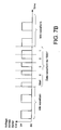
- Fig. 7B illustrates an exemplary waveform across the setter coil 38.
- the idle waveform e.g., squarewave
- a squarewave is bi-phase modulated in order to communicate data. The particular values of such data depends on the particular information to be transferred to the projectile 22 as will be appreciated.
- the target system 36 includes the target coil 32.
- the voltage across the setter coil 38 is induced across the target coil 32.
- a diode D3 serves to rectify the idle waveform as well as the data waveform across the target coil 32 so as to build up a DC charge across capacitor C1.
- the charge is coupled across a load resistor LOAD which represents any load circuitry included in the target electronics.
- a voltage regulator 114 utilizes the DC voltage across the resistor LOAD as an input voltage, and provides regulated DC power Vcc to the remaining target electronics within the projectile 22. In this manner, the setter system 24 is able to deliver power to the target system 36 via the target coil 32.
- the target system 36 further includes a resistor divider comprising resistors R1, R2 and Rd.
- the resistor Rd is strapped across the target coil 32. As the voltage across the resistor Rd varies, the voltage at the node between resistors R1 and R2 varies. The voltage at the node between resistors R1 and R2 is input to a comparator U1. Diodes D4 and D5 are configured to limit the amplitude of the voltage input to the comparator U1. Resistors R3 and R4 are configured to provide a reference voltage to the other input of the comparator U1. Thus, the bi-phase modulated signal induced across the target coil 32 is output by the comparator U1 as a bi-phase modulated signal.
- Additional demodulation circuitry included in the data receiver 62 can then demodulate the data and provide it to the control logic for carrying out the necessary operations within the projectile 22 as will be appreciated. In this manner, the setter system 24 is able to deliver data to the target system 36 using the same target coil 32.
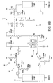
- Figs. 8A and 8B illustrate schematically another embodiment of the setter system 24 and the target system 36.
- the setter system 24 includes separate power driver and data driver circuits.
- Fig. 8A illustrates the relevant circuitry with respect to the power transfer aspect
- Fig. 8B illustrates the relevant circuitry with respect to the data transfer aspect.
- Fig. 8A power is delivered and received via circuitry similar to that described above in relation to the embodiment of Fig. 7A . That is, the gate drivers 110 and 112 drive the transistors Q1 and Q2 in opposite phase so as to excite the setter coil 38 with a square wave when transferring power. The voltage induced across the target coil 32 is rectified and stored across the capacitor C1. The voltage regulator 114 then regulates the voltage to provide the voltage supply Vcc.
- Fig. 8B illustrates circuitry for transferring data from the setter system 24 to the target system 36.
- data is transferred during gaps in the power waveform.
- the gaps are large enough to allow the flux in the coils 32 and 38 to mostly or completely collapse and to allow data to be transmitted before the power waveform resumes.
- a capacitor or other charge storage device in the target system 36 provides power during the brief gap in the power waveform.
- the amplitude of the data waveform may be much lower than the power amplitude. This makes it more difficult for a third party to intercept sensitive data.
- the data waveform is produced by driving bi-polar transistors Q3 and Q4 (via resistors R9-R13 and transistor Q5) in opposite phase and at lower amplitudes based on the data to be transmitted.
- the target system 36 receives and demodulates the data in the same manner described above with respect to the embodiment of Fig. 7A .
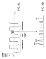
- Fig. 8C shows an exemplary waveform of the voltage across the setter coil 38 according to the embodiment of Figs. 8A and 8B .
- the gate drivers 110, 112 and power transistors Q1 and Q2 excite the setter coil 38 to produce a square wave which is induced onto the target coil 32.
- the square wave is rectified and used to charge capacitor C1 and provide a voltage to the Load resistor and voltage regulator 114.
- the gate drivers 110 and 112 remain off and no voltage is placed across the setter coil 38.
- the magnetic fields then decay to so that the voltage across the setter coil 38 becomes substantially zero. Then, during a data period as represented in Fig.
- the data driver circuit 52 of the setter system 24 as represented in Fig. 8B modulates the data onto a data waveform across the setter coil 38 by turning on/off transistors Q3 and Q4.
- Fig. 8D illustrates an exemplary data waveform in more detail. Following the data waveform, the power waveform is repeated.
- the basic structure of the data driver 64 can be similar to that of the data driver 52 in the setter system 24.
- the data receiver 54 of the setter system 24 can be configured similar to the data receiver 62 in the target system 36.
Landscapes
- Engineering & Computer Science (AREA)
- General Engineering & Computer Science (AREA)
- Near-Field Transmission Systems (AREA)
- Aiming, Guidance, Guns With A Light Source, Armor, Camouflage, And Targets (AREA)
Claims (16)
- Projektil mit:einem Rumpf (23);einer Nutzlast (26) innerhalb des Rumpfs (23);einem Zielsystem innerhalb des Rumpfs (23), um das Projektil zu betreiben; undeiner induktiven Schnittstelle, die als Teil des Zielsystems (36) die Übertragung von Energie und Daten zwischen dem Zielsystem (36) und einem externen Einstellsystem (24) erlaubt, dadurch gekennzeichnet, dass die induktive Schnittstelle aufweist:einen Magnetkern (74), der eine Zusammensetzung aus einem Ferritmaterial und einem Nicht-Ferritmaterial umfasst; undeine gleiche Spule (32), die um den Magnetkern (74) gewickelt ist und zur Übertragung der Energie und der Daten dient.
- Projektil nach Anspruch 1, wobei der Magnetkern (74) einen Ferritmaterialgehalt im Bereich von etwa 50 % bis etwa 90 % des Gewichts hat.
- Projektil nach Anspruch 2, wobei der Magnetkern (74) einen Ferritmaterialgehalt im Bereich von etwa 70 % bis etwa 80 % des Gewichts hat.
- Projektil nach Anspruch 1, wobei der Magnetkern (74) ein Kunststoffmaterial aufweist, das mit Ferritmaterial imprägniert ist.
- Projektil nach Anspruch 4, wobei das Kunststoffmaterial mit einem Mangan-Zink-Ferrit imprägniert ist.
- Projektil nach Anspruch 4, wobei das Kunststoffmaterial mit einem Nickel-Zink-Ferrit imprägniert ist.
- Projektil nach Anspruch 4, wobei das Kunststoffmaterial Nylon aufweist.
- Projektil nach Anspruch 1, wobei der Magnetkern (74) aus einem extrudierten Material geformt ist.
- Projektil nach Anspruch 1, wobei der Rumpf (23) einen konischen Nasenabschnitt (30) aufweist, und der Magnetkern (74) eine hohle konische Form aufweist, die ausgelegt ist, um in den Nasenabschnitt hineinzupassen und einer Kontur des Nasenabschnitts (30) zu folgen.
- Projektil nach Anspruch 9, wobei der Nasenabschnitt einen mittleren zylindrischen Abschnitt (80) entlang einer mittleren Achse der Nase aufweist, der in einen hohlen mittleren Abschnitt des Magnetkerns (74) passt, so dass die innere und die äußere Fläche des Magnetkerns (74) zwischen Wänden des Nasenabschnitts gehalten wird.
- Projektil nach Anspruch 10, wobei der mittlere zylindrische Abschnitt (80) einen Vorsprung (82) für eine Schnappverbindung aufweist, um den Nasenabschnitt (30) und den Magnetkern (74) am Rest des Rumpfs (23) zu befestigen.
- Projektil nach Anspruch 11, wobei eine Spannungswellenform, die über die gleiche Spule (32) induziert wird, einen Leerlaufwellenformabschnitt aufweist, der Energie zum Betreiben des Zielsystems enthält und einen Datenwellenformabschnitt, der Daten repräsentiert, die an das Zielsystem gesendet werden.
- Projektil nach Anspruch 12, wobei die Leerlaufwellenform und die Datenwellenform im Wesentlichen die gleiche Amplitude haben.
- Projektil nach Anspruch 13, wobei die Datenwellenform ebenfalls dazu dient, Energie zum Betreiben des Zielsystems zu liefern.
- Projektil nach Anspruch 1, wobei eine Spannungswellenform, die über die gleiche Spule (32) induziert wird, einen Energiewellenformabschnitt aufweist, der Energie zum Betreiben des Zielsystems enthält, und einen Datenwellenformabschnitt aufweist, der Daten repräsentiert, die zu dem Zielsystem gesendet werden, wobei die Amplitude des Datenwellenformabschnitts wesentlich kleiner als eine Amplitude des Energiewellenformabschnitts ist.
- Projektil nach Anspruch 15, wobei die Spannungswellenform einen Feldzusammenbruchabschnitt umfasst zwischen dem Energiewellenformabschnitt und dem Datenwellenformabschnitt.
Applications Claiming Priority (2)
| Application Number | Priority Date | Filing Date | Title |
|---|---|---|---|
| US10/670,044 US7077045B2 (en) | 2003-09-24 | 2003-09-24 | Projectile inductive interface for the concurrent transfer of data and power |
| PCT/US2004/028716 WO2005088235A2 (en) | 2003-09-24 | 2004-09-03 | Projectile inductive interface for the concurrent transfer of data and power |
Publications (2)
| Publication Number | Publication Date |
|---|---|
| EP1664665A2 EP1664665A2 (de) | 2006-06-07 |
| EP1664665B1 true EP1664665B1 (de) | 2008-07-16 |
Family
ID=34313822
Family Applications (1)
| Application Number | Title | Priority Date | Filing Date |
|---|---|---|---|
| EP04821604A Expired - Lifetime EP1664665B1 (de) | 2003-09-24 | 2004-09-03 | Induktive geschoss-schnittstelle für die gleichzeitige übertragung von daten und energie |
Country Status (4)
| Country | Link |
|---|---|
| US (1) | US7077045B2 (de) |
| EP (1) | EP1664665B1 (de) |
| DE (1) | DE602004015124D1 (de) |
| WO (1) | WO2005088235A2 (de) |
Families Citing this family (29)
| Publication number | Priority date | Publication date | Assignee | Title |
|---|---|---|---|---|
| NZ539770A (en) * | 2005-04-29 | 2007-10-26 | Auckland Uniservices Ltd | Inductively coupled power transfer system |
| FR2887976A1 (fr) * | 2005-07-04 | 2007-01-05 | Lacroix Soc E | Dispositif d'allumage sans fil a resonance |
| EP1958218A2 (de) | 2005-12-02 | 2008-08-20 | Koninklijke Philips Electronics N.V. | Kopplungssystem |
| WO2008112012A2 (en) * | 2006-10-04 | 2008-09-18 | Raytheon Company | Supercapacitor power supply |
| EP2069712B1 (de) * | 2006-10-04 | 2016-11-23 | Raytheon Company | Induktive kraftübertragung |
| US8117955B2 (en) * | 2006-10-26 | 2012-02-21 | Lone Star Ip Holdings, Lp | Weapon interface system and delivery platform employing the same |
| US7679423B1 (en) | 2006-12-22 | 2010-03-16 | The United States Of America As Represented By The Secretary Of The Navy | Switch circuit for magnetic-induction interface |
| WO2009045573A1 (en) * | 2007-06-08 | 2009-04-09 | Raytheon Company | Methods and apparatus for intercepting a projectile |
| US8850045B2 (en) | 2008-09-26 | 2014-09-30 | Qualcomm Incorporated | System and method for linking and sharing resources amongst devices |
| US8868939B2 (en) * | 2008-09-26 | 2014-10-21 | Qualcomm Incorporated | Portable power supply device with outlet connector |
| US8527688B2 (en) * | 2008-09-26 | 2013-09-03 | Palm, Inc. | Extending device functionality amongst inductively linked devices |
| NZ592333A (en) * | 2008-10-24 | 2014-10-31 | Battelle Memorial Institute | Electronic detonator system |
| FR2938638A1 (fr) * | 2008-11-18 | 2010-05-21 | Nexter Munitions | Procede de programmation d'une fusee de projectile et dispositif de programmation permettant la mise en oeuvre d'un tel procede |
| FR2952425B1 (fr) * | 2009-11-06 | 2011-10-28 | Nexter Munitions | Dispositif de programmation d'une fusee de projectile |
| IT1400621B1 (it) * | 2010-05-13 | 2013-06-14 | Oto Melara Spa | Sistema di comunicazione dati ad una spoletta di un'arma da fuoco. |
| EP2576274B1 (de) * | 2010-05-26 | 2014-01-29 | ABB Research Ltd. | Drahtlose leistungsempfangseinheit, drahtlose leistungsübertragungseinheit, drahtlose leistungsübertragungsvorrichtung und verwendung von einer leistungsübertragungsvorrichtung |
| US8723493B2 (en) | 2010-10-06 | 2014-05-13 | Alliant Techsystems Inc. | Methods and apparatuses for inductive energy capture for fuzes |
| US8446132B2 (en) | 2011-02-04 | 2013-05-21 | Alliant Techsystems Inc. | Methods and apparatuses for electrical pulse energy capture |
| US8365666B1 (en) * | 2011-02-08 | 2013-02-05 | The United States Of America As Represented By The Secretary Of The Army | Modular breaching and demolition system |
| US10197611B2 (en) | 2016-05-20 | 2019-02-05 | Raytheon Company | Systems and methods for testing arm and fire devices |
| US10077970B2 (en) * | 2016-12-12 | 2018-09-18 | Bae Systems Information And Electronic Systems Integration Inc. | System and method for stores communications |
| SE541930C2 (en) | 2017-09-28 | 2020-01-07 | Bae Systems Bofors Ab | Method and system for inductive programming of a fuze |
| US11578956B1 (en) * | 2017-11-01 | 2023-02-14 | Northrop Grumman Systems Corporation | Detecting body spin on a projectile |
| US10852116B2 (en) * | 2019-03-06 | 2020-12-01 | Bae Systems Information And Electronic Systems Integration Inc. | Fuze setter interface for powering and programming a fuze on a guided projectile |
| US20200109931A1 (en) * | 2018-09-07 | 2020-04-09 | CSP Consulting, LLC | Non-Lethal Projectile Construction and Launcher |
| DE102020108567A1 (de) | 2020-03-27 | 2021-09-30 | Krauss-Maffei Wegmann Gmbh & Co. Kg | Programmiervorrichtung |
| EP4150289A4 (de) * | 2020-05-12 | 2024-05-22 | BAE SYSTEMS Information and Electronic Systems Integration, Inc. | Drahtlose multi-fuze-einstellvorrichtungsschnittstelle |
| US11573069B1 (en) * | 2020-07-02 | 2023-02-07 | Northrop Grumman Systems Corporation | Axial flux machine for use with projectiles |
| US12313389B1 (en) | 2022-03-11 | 2025-05-27 | Northrop Grumman Systems Corporation | Tunable safe and arming devices and methods of manufacture |
Family Cites Families (14)
| Publication number | Priority date | Publication date | Assignee | Title |
|---|---|---|---|---|
| EP0003396A1 (de) * | 1978-02-01 | 1979-08-08 | Imperial Chemical Industries Plc | Steuerkreis zum Erregen einer elektrisch gezündeten Last |
| US5101728A (en) | 1983-11-17 | 1992-04-07 | Simmonds Precision Products, Inc. | Precision guided munitions alternator |
| GB2153495B (en) | 1984-01-25 | 1987-10-21 | Plessey Co Plc | Improvements relating to variable timing and power storage arrangements |
| US5010728A (en) * | 1985-10-18 | 1991-04-30 | Williams International Corporation | Solid fuel turbine engine |
| DE3827374C1 (de) | 1988-08-12 | 1994-07-28 | Honeywell Ag | Verfahren und Vorrichtung zur induktiven Laufzeitprogrammierung |
| DE59100529D1 (de) | 1990-07-19 | 1993-12-02 | Contraves Ag | Empfangsspule für einen programmierbaren Geschosszünder. |
| US5343795A (en) * | 1991-11-07 | 1994-09-06 | General Electric Co. | Settable electronic fuzing system for cannon ammunition |
| US5497704A (en) * | 1993-12-30 | 1996-03-12 | Alliant Techsystems Inc. | Multifunctional magnetic fuze |
| SE506554C2 (sv) | 1996-04-18 | 1998-01-12 | Bofors Ab | Sätt och anordning för programmering av granater |
| DE19756357B4 (de) | 1997-12-18 | 2007-06-28 | Dynamit Nobel Gmbh Explosivstoff- Und Systemtechnik | Einrichtung zur Induktion eines Magnetfelds im Mündungsbereich einer Abschußeinrichtung |
| US6268785B1 (en) * | 1998-12-22 | 2001-07-31 | Raytheon Company | Apparatus and method for transferring energy across a connectorless interface |
| US6176168B1 (en) | 1999-04-29 | 2001-01-23 | Alliant Techsystems Inc. | Transmitter coil, improved fuze setter circuitry for adaptively tuning the fuze setter circuit for resonance and current difference circuitry for interpreting a fuze talkback message |
| DE10004582C1 (de) * | 2000-02-02 | 2001-08-30 | Honeywell Ag | Elektronischer Geschoßzünder |
| US6557450B1 (en) * | 2002-02-13 | 2003-05-06 | The United States Of America As Represented By The Secretary Of The Navy | Power indicating setter system for inductively-fuzed munitions |
-
2003
- 2003-09-24 US US10/670,044 patent/US7077045B2/en not_active Expired - Lifetime
-
2004
- 2004-09-03 DE DE602004015124T patent/DE602004015124D1/de not_active Expired - Lifetime
- 2004-09-03 WO PCT/US2004/028716 patent/WO2005088235A2/en not_active Ceased
- 2004-09-03 EP EP04821604A patent/EP1664665B1/de not_active Expired - Lifetime
Also Published As
| Publication number | Publication date |
|---|---|
| US20050061191A1 (en) | 2005-03-24 |
| US7077045B2 (en) | 2006-07-18 |
| EP1664665A2 (de) | 2006-06-07 |
| DE602004015124D1 (de) | 2008-08-28 |
| WO2005088235A3 (en) | 2005-12-29 |
| WO2005088235A2 (en) | 2005-09-22 |
Similar Documents
| Publication | Publication Date | Title |
|---|---|---|
| US7077045B2 (en) | Projectile inductive interface for the concurrent transfer of data and power | |
| EP2145152B1 (de) | Geführtes projektil mit strom- und steuerungsmechanismus | |
| US7913606B2 (en) | Inductive power transfer | |
| US4603637A (en) | Variable density frangible projectile | |
| CN102686969B (zh) | 用于将能量传输到一个射弹上的方法和装置 | |
| US6135387A (en) | Method for autonomous guidance of a spin-stabilized artillery projectile and autonomously guided artillery projectile for realizing this method | |
| KR100639045B1 (ko) | 발사체속도측정시스템및속도계산방법 | |
| US4080869A (en) | Apparatus for generating an electrical ignition current in a fuze of a projectile | |
| US11525654B2 (en) | Power generator for a projectile | |
| KR102005691B1 (ko) | 무선 기폭 뇌관, 무선 기폭 시스템, 및 무선 기폭 방법 | |
| US4779511A (en) | Disposal dearmer for EOD applications | |
| EP0675335A2 (de) | Vorrichtung und Verfahren zum Kontrollieren des Rollens | |
| KR101647540B1 (ko) | 프로그래밍 가능한 탄약 | |
| US7946209B2 (en) | Launcher for a projectile having a supercapacitor power supply | |
| US12055375B2 (en) | Axial flux machine for use with projectiles | |
| US4454815A (en) | Reprogrammable electronic fuze | |
| ES2253841T3 (es) | Dispositivo para inducir un campo magnetico en la zona de la boca de un dispositivo de disparo. | |
| US11009329B2 (en) | Projectile fuze assembly and methods of assembling and use | |
| US5101728A (en) | Precision guided munitions alternator | |
| KR101968326B1 (ko) | 유도비행체 사출 제어 시스템 및 방법 | |
| US11725917B2 (en) | Projectile having a caliber of less than 13 mm and a system for tracking a projectile | |
| US20230194225A1 (en) | Lethal Projectile Construction and Launcher | |
| CN219077529U (zh) | 一种基于电磁发射的飞网发射装置 | |
| EA043434B1 (ru) | Автоматизированные системы и устройства для хранения, транспортировки, раздачи и отслеживания компонентов устройства инициирования, конфигурируемых для инициирования составов взрывчатых материалов | |
| US8222755B2 (en) | Energy recycling structure |
Legal Events
| Date | Code | Title | Description |
|---|---|---|---|
| PUAI | Public reference made under article 153(3) epc to a published international application that has entered the european phase |
Free format text: ORIGINAL CODE: 0009012 |
|
| 17P | Request for examination filed |
Effective date: 20060308 |
|
| AK | Designated contracting states |
Kind code of ref document: A2 Designated state(s): AT BE BG CH CY CZ DE DK EE ES FI FR GB GR HU IE IT LI LU MC NL PL PT RO SE SI SK TR |
|
| AX | Request for extension of the european patent |
Extension state: AL HR LT LV MK |
|
| DAX | Request for extension of the european patent (deleted) | ||
| RBV | Designated contracting states (corrected) |
Designated state(s): DE FR GB IT SE |
|
| 17Q | First examination report despatched |
Effective date: 20070402 |
|
| GRAP | Despatch of communication of intention to grant a patent |
Free format text: ORIGINAL CODE: EPIDOSNIGR1 |
|
| GRAS | Grant fee paid |
Free format text: ORIGINAL CODE: EPIDOSNIGR3 |
|
| GRAA | (expected) grant |
Free format text: ORIGINAL CODE: 0009210 |
|
| AK | Designated contracting states |
Kind code of ref document: B1 Designated state(s): DE FR GB IT SE |
|
| REG | Reference to a national code |
Ref country code: GB Ref legal event code: FG4D |
|
| REF | Corresponds to: |
Ref document number: 602004015124 Country of ref document: DE Date of ref document: 20080828 Kind code of ref document: P |
|
| REG | Reference to a national code |
Ref country code: SE Ref legal event code: TRGR |
|
| PLBE | No opposition filed within time limit |
Free format text: ORIGINAL CODE: 0009261 |
|
| STAA | Information on the status of an ep patent application or granted ep patent |
Free format text: STATUS: NO OPPOSITION FILED WITHIN TIME LIMIT |
|
| 26N | No opposition filed |
Effective date: 20090417 |
|
| REG | Reference to a national code |
Ref country code: FR Ref legal event code: PLFP Year of fee payment: 13 |
|
| REG | Reference to a national code |
Ref country code: FR Ref legal event code: PLFP Year of fee payment: 14 |
|
| REG | Reference to a national code |
Ref country code: FR Ref legal event code: PLFP Year of fee payment: 15 |
|
| PGFP | Annual fee paid to national office [announced via postgrant information from national office to epo] |
Ref country code: FR Payment date: 20180712 Year of fee payment: 15 Ref country code: DE Payment date: 20180821 Year of fee payment: 15 Ref country code: IT Payment date: 20180919 Year of fee payment: 15 |
|
| PGFP | Annual fee paid to national office [announced via postgrant information from national office to epo] |
Ref country code: GB Payment date: 20180829 Year of fee payment: 15 Ref country code: SE Payment date: 20180910 Year of fee payment: 15 |
|
| REG | Reference to a national code |
Ref country code: DE Ref legal event code: R119 Ref document number: 602004015124 Country of ref document: DE |
|
| PG25 | Lapsed in a contracting state [announced via postgrant information from national office to epo] |
Ref country code: SE Free format text: LAPSE BECAUSE OF NON-PAYMENT OF DUE FEES Effective date: 20190904 |
|
| REG | Reference to a national code |
Ref country code: SE Ref legal event code: EUG |
|
| PG25 | Lapsed in a contracting state [announced via postgrant information from national office to epo] |
Ref country code: DE Free format text: LAPSE BECAUSE OF NON-PAYMENT OF DUE FEES Effective date: 20200401 |
|
| PG25 | Lapsed in a contracting state [announced via postgrant information from national office to epo] |
Ref country code: IT Free format text: LAPSE BECAUSE OF NON-PAYMENT OF DUE FEES Effective date: 20190903 |
|
| GBPC | Gb: european patent ceased through non-payment of renewal fee |
Effective date: 20190903 |
|
| PG25 | Lapsed in a contracting state [announced via postgrant information from national office to epo] |
Ref country code: GB Free format text: LAPSE BECAUSE OF NON-PAYMENT OF DUE FEES Effective date: 20190903 Ref country code: FR Free format text: LAPSE BECAUSE OF NON-PAYMENT OF DUE FEES Effective date: 20190930 |