EP1664446B1 - Baggerzahn mit flügeln - Google Patents
Baggerzahn mit flügeln Download PDFInfo
- Publication number
- EP1664446B1 EP1664446B1 EP04780426A EP04780426A EP1664446B1 EP 1664446 B1 EP1664446 B1 EP 1664446B1 EP 04780426 A EP04780426 A EP 04780426A EP 04780426 A EP04780426 A EP 04780426A EP 1664446 B1 EP1664446 B1 EP 1664446B1
- Authority
- EP
- European Patent Office
- Prior art keywords
- tooth
- digging
- digging tooth
- wing
- edge
- Prior art date
- Legal status (The legal status is an assumption and is not a legal conclusion. Google has not performed a legal analysis and makes no representation as to the accuracy of the status listed.)
- Not-in-force
Links
Images


Classifications
-
- E—FIXED CONSTRUCTIONS
- E02—HYDRAULIC ENGINEERING; FOUNDATIONS; SOIL SHIFTING
- E02F—DREDGING; SOIL-SHIFTING
- E02F9/00—Component parts of dredgers or soil-shifting machines, not restricted to one of the kinds covered by groups E02F3/00 - E02F7/00
- E02F9/28—Small metalwork for digging elements, e.g. teeth scraper bits
- E02F9/2808—Teeth
- E02F9/2816—Mountings therefor
- E02F9/2833—Retaining means, e.g. pins
- E02F9/2841—Retaining means, e.g. pins resilient
-
- E—FIXED CONSTRUCTIONS
- E02—HYDRAULIC ENGINEERING; FOUNDATIONS; SOIL SHIFTING
- E02F—DREDGING; SOIL-SHIFTING
- E02F9/00—Component parts of dredgers or soil-shifting machines, not restricted to one of the kinds covered by groups E02F3/00 - E02F7/00
- E02F9/28—Small metalwork for digging elements, e.g. teeth scraper bits
- E02F9/2808—Teeth
- E02F9/2858—Teeth characterised by shape
-
- E—FIXED CONSTRUCTIONS
- E02—HYDRAULIC ENGINEERING; FOUNDATIONS; SOIL SHIFTING
- E02F—DREDGING; SOIL-SHIFTING
- E02F9/00—Component parts of dredgers or soil-shifting machines, not restricted to one of the kinds covered by groups E02F3/00 - E02F7/00
- E02F9/28—Small metalwork for digging elements, e.g. teeth scraper bits
- E02F9/2883—Wear elements for buckets or implements in general
Definitions
- the present invention generally relates to ground engaging implements and, more particularly, to a digging tooth adapted to be secured to and project forward from a leading or forward edge of a bucket or the like.
- Buckets of varying sizes and shapes are commonly arranged in operable combination with backhoes, front loaders, excavators and related earthworking equipment. Most buckets include areas, i.e ., the leading bucket edge, bucket side walls, etc., which are exposed and, thus, are highly susceptible to wear, especially when the bucket is used in abrasive and rocky environments.
- a one-piece, transversely elongated base edge or lip is welded to other bucket walls and serves as a leading edge for the bucket.
- the bucket edge is frequently provided with a sharpened or beveled design to enhance ground penetration capability for the bucket.
- a significant force is required to allow the bucket edge to penetrate such ground conditions.
- Each digging tooth has a transverse edge at a forward or front end thereof for fracturing the ground in advance of and, thus, promoting penetration by the remainder of the digging tooth and, ultimately, by the bucket edge.
- having the digging tooth fracture the ground in advance of the bucket edge furthermore facilitates gathering of ground material into the bucket
- Some digging teeth are of one-piece or unitary construction and design.
- a rear portion of a one-piece digging tooth is typically configured for attachment, as by welding, to the bucket edge or lip, while the remaining portion of the digging tooth is configured to extend forward from the bucket edge to fracture the ground in advance of the bucket edge penetrating the ground.
- a vast preponderance of ground engaging teeth are designed as two-part systems.
- a conventional two-part digging tooth system or assembly includes a digging/ground engaging tooth and an adapter arranged in operable combination with each other.
- the adapter includes a base or mounting portion and a nose portion projecting forward from the bucket edge and to which the digging tooth is releasably attached.
- the base of the adapter is secured, as by welding to the leading edge of the bucket.
- another wear component in the form of a cap, is provided rearwardly of the digging tooth for adding protection to the adapter against wear.
- the leading or cutting edge of the bucket is typically quite hard to protect against impacts, wear, and undue stress associated with typical excavating operations, protection of the leading or cutting bucket edge remains of paramount importance. While lengthwise portions of the bucket edge are protected by the mounting portion of either design of the digging tooth, those portions of the bucket edge spanning the distance between adjacent laterally spaced digging teeth remain exposed to the same harsh and wearing environment as the digging teeth. Unfortunately, the front cutting edge of the digging tooth provides only a limited ground fracturing zone in advance of the bucket cutting edge.
- the components of two-part digging tooth systems are typically maintained in operable combination relative to each other by various types of retaining devices.
- the majority of known retaining devices are either of a flex-pin type or a pin and retainer type.
- retaining devices are either of a flex-pin type or a pin and retainer type.
- Hundreds of thousands of older backhoes use a well known flex-pin retainer for maintaining a tooth and adapter in operable combination with each other.
- Pin and retainer systems are also used on tens of thousands of older ground engaging implements and machines for maintaining a digging tooth and adapter in operable combination relative to each other.
- As ergonomics play more of a part in digging tooth designs, vertically and even diagonally disposed retainer devices and designs have also become increasingly more popular due to their convenient access.
- Compatibility between component parts of the two-part digging tooth system is also an important concern. Because of the immense quantity of existing implements, the presence and location of certain design features on known two-part digging tooth systems requires consideration when contemplating changes to either component of the digging system. That is, when design changes are considered for either component of a two-part digging tooth assembly, the ancillary affects such changes can have on existing bucket designs should also be carefully considered. To reduce costs to the end user, most changes to either component of the two-part digging tooth system should be compatible with equipment already in the field. In this regard, lost production and costly welding and replacement repairs continue to plague the industry.
- WO96/03023 A1 discloses a ground working tool which includes a body, a pair of wings integral with or attached to the body and a terminal ground contacting protection located at a free end of each of the wings.
- EP 1 403 439 A2 discloses a tooth block to be attached to a bucket for a shovel machine, wherein the tooth block is removably attached to the bucket through an adapter member provided at the lip of the bucket and projecting therefrom.
- JP2001/254383 A and JP2003/1478111 A each disclose a ground working tool.
- a digging tooth as defined in claim 1 adapted to extend forward from a digging implement having a transversely extending edge.
- the digging tooth defines a longitudinal centerline and has a forward end portion, with a cutting edge extending thereacross, and a rear end portion configured for attachment to the edge of the implement.
- the digging tooth further includes upper and lower angularly diverging surfaces having opposed side surfaces therebetween.
- the digging tooth further includes a wing projecting laterally outwardly from each side surface on the tooth. Each wing is formed integral with the remainder of the tooth and has upper and lower planar surfaces each extending in a direction generally paralleling the cutting edge across the forward end portion of the tooth.
- each wing has a laterally widened rear portion, a laterally narrowed forward portion, and an outer edge extending therebetween for providing the tooth with a progressively widening ground fracturing zone whereby adding significant wear protection for the edge of the implement.
- an outer edge of each wing has a rear portion that extends in generally parallel relation to the centerline axis of the digging tooth for a longitudinal distance ranging between about one third and one half of the overall distance between the rear end portion and the forward end portion of the digging tooth, said outer edge has a portion that laterally converges toward the centerline of the digging tooth and a portion that extends along the laterally narrowed portion of each wing in generally parallel relation relative to the respective side surface of the digging tooth from which the wing laterally extends.
- the rear end portion of the digging tooth is provided with a blind cavity for receiving and accommodating a lengthwise section of a nose portion of an adapter extending from the bucket edge or lip.
- the blind cavity at the rear end portion of the tooth has a generally rhombus-like configuration for a major lengthwise portion thereof
- the laterally widened portion of each wing extends outward and forward from the rearward portion of the tooth.
- the digging tooth further defines a bore opening to the blind cavity for accommodating at least a portion of a retaining apparatus used to releasably secure the tooth and adapter in operable combination relative to each other.
- a retaining apparatus used to releasably secure the tooth and adapter in operable combination relative to each other.
- one of the upper and lower generally planar surfaces on each wing of the tooth further defines an open groove or channel arranged in general alignment relative to each other and relative to an axis of the bore defined by the tooth.
- the open channel on the planar surface of each wing serves to both accommodate and align a pin of the retaining apparatus with the bore defined by the tooth.
- an area, arranged in proximate relation relative to the bore defined by the tooth, is configured to impart compression to a conventional flex-pin retaining apparatus as the flex-pin is inserted into a position to maintain the tooth and adapter in operable combination relative to each other.
- an area, arranged in proximate relation relative to the bore on the digging tooth, is configured to inhibit inadvertent axial shifting of the retaining apparatus relative to the adapter or tooth.
- each wing extends laterally outward from an area on opposed side surfaces of the tooth proximately midway between the upper and lower surfaces of the digging tooth.
- the upper generally planar surface of each wing on the tooth is configured to protect ends of the retaining apparatus extending beyond opposed sides of the digging tooth.
- an elongated outer edge portion on each wing is configured with a cutting edge.
- an elongated digging tooth adapted to extend forward from a digging implement having a transversely extending edge.
- the digging tooth defines a central axis and has a forward end portion, with a transverse cutting edge, and a rear end portion configured for attachment to the transversely extending edge of the implement.
- the digging tooth further includes upper and lower angularly diverging surfaces having opposed side surfaces therebetween.
- the digging tooth further includes wing structure projecting generally horizontally and laterally outward from an area on one side of the tooth.
- the wing structure is formed integral with the remainder of the digging tooth and has generally horizontal upper and lower surfaces. The upper and lower surfaces of the wing structure are disposed between and in other than planar relationship relative to the upper and lower surfaces of the digging tooth.
- the wing structure has a laterally widened rear portion, a laterally narrowed front portion, and an outer edge extending therebetween and, for a major portion of the length thereof, converges toward the central axis of the tooth so as to provide the digging tooth with a widening ground penetration zone for facilitating penetration of the bucket edge.
- a major lengthwise portion of the outer edge of the wing structure is configured to enhance the ability of the wring to slice through and fracture the ground.
- the wing structure is disposed on the tooth in generally symmetrical relation relative to the central axis of the tooth whereby permitting the digging tooth to be reversed about he central axis.
- the digging tooth is provided with a second wing structure is provided on and projecting generally horizontally and laterally outward from an area on an opposite side of the tooth.
- the second wing structure has generally horizontal upper and lower surfaces, with the upper and lower surfaces of the second wing structure being disposed between and in other than planar relationship relative to the upper and lower surfaces of the digging tooth.
- the second wing structure preferably has a rear laterally widened portion, a laterally narrowed front portion, and an outer edge extending therebetween and converging toward the central axis of said tooth whereby providing the digging tooth with a widening ground penetration zone for facilitating penetration of the transversely extending edge on the digging implement.
- the wing structure extending from those areas on opposed sides of the tooth are arranged proximately midway between the upper and lower surfaces of said tooth.
- the rear end portion of the digging tooth is provided with a blind cavity for receiving and accommodating a lengthwise section of a nose portion of an adapter extending from the bucket edge or lip.
- a marginal edge extending about the blind cavity provided at the rear end portion of the tooth has a generally rhombus-like configuration for a major lengthwise portion thereof.
- the digging tooth further defies a pair of axially aligned bores which each open to the blind cavity and are disposed along an axis extending at an angle ranging between about 25° and about 65° relative to the transverse cutting edge at the forward end portion of the tooth.
- each wing extends outward and forward from the rear end portion of the tooth.
- the digging tooth further includes opposed surfaces arranged within the blind cavity defined by the tooth for adding stability to the tooth during a digging operation.
- a bucket having a forward edge and a plurality of two-part digging tooth assemblies connected to the edge in side-by-side relation.
- Each digging tooth assembly includes an adapter having a nose portion extending forward from the bucket edge and to which a replaceable digging tooth is secured.
- Each digging tooth has a forward end, with an edge transversely extending thereacross, a rear end, positioned adjacent to the bucket edge and defining a blind cavity for receiving the nose portion of the adapter, an upper surface extending forward and downwardly from the rearward end and toward the forward end of said digging tooth, and a lower surface extending forward and upwardly from the rearward end and toward the forward end of the digging tooth.
- Each digging tooth further has wing structure including a pair of wings extending outwardly in a direction generally parallel to the forward edge on the tooth from an area on each side of the tooth proximate midway between the upper and lower surfaces thereof.
- Each wing on the tooth has a laterally widened rear portion and a laterally narrowed front portion such that, for a major length thereof, an outer edge of each wing converges toward the central axis of the tooth and diverges relative to the outer edge of a wing on an adjacent tooth.
- the wings on each tooth are designed to protect the portion of the bucket edge disposed between adjacent tooth assemblies against wear.
- the rear end portion of the digging tooth is configured with a blind cavity for receiving and accommodating a lengthwise section of a nose portion of an adapter extending from the transversely expending edge of the digging implement.
- the blind cavity can have either a rhombus-like or a generally rectangular cross-sectional configuration.
- each tooth also includes a bore opening to the blind cavity at the rear end of the tooth for accommodating at least a portion of an apparatus used to releasably secure the tooth and adapter in operable combination.
- the wing on each digging tooth has upper and lower generally planar surfaces, and with the outer edge of the wing on each digging tooth having angularly converging surfaces to provide each wing with a cutting edge for facilitating ground penetration.
- one of the generally planar surfaces on each wing of the digging tooth further defines an open channel or groove arranged in general alignment with an axis of the bore defined by the tooth for both accommodating and aligning a flex-pin of the retaining apparatus with said the bore defined by the tooth.
- an area of the digging tooth, arranged in proximate relation relative to the bore is preferably configured to compress a flex-pin retaining apparatus as the flex-pin is inserted into a position to maintain said tooth and adapter in operable combination relative to each other.
- an area of the digging tooth arranged in proximate relation relative to the bore is preferably configured to inhibit inadvertent axial shifting of the retaining apparatus relative to said adapter or tooth.
- the generally planar surface of each wing defining the channel is disposed and configured to protect a lengthwise portion of said retaining apparatus extending beyond either side of said digging tooth.
- the tooth of each of digging tooth assembly is configured such that the blind cavity has a generally rhombus-like cross-sectional configuration.
- the tooth of each digging tooth assembly defines a pair of axially aligned bores opening to the tooth cavity and disposed along an axis extending at an angle ranging between about 25° and about 65 ° relative to the transversely extending edge at the forward end of the tooth.
- a ground engaging tooth adapted to be mounted to a digging implement and having a wear component arranged rearwardly thereof.
- the ground engaging tooth defines a central axis and has a forward end portion, with an edge extending transversely thereacross, and a rear end portion.
- the digging tooth further includes upper and lower angularly diverging surfaces having opposed side surfaces therebetween.
- the digging tooth further includes a free ended projection laterally outwardly from each side surface on the tooth.
- Each wing is formed integral with the remainder of the tooth and has upper and lower planar surfaces each extending in a direction generally paralleling the cutting edge across the forward end portion of the tooth.
- each wing has a laterally widened rear portion, a laterally narrowed forward portion, and an outer edge extending therebetween for providing the tooth with a progressively widening ground fracturing zone whereby adding significant wear protection for the edge of the implement.
- the rear end portion of the digging tooth is provided with a blind cavity for receiving and accommodating a lengthwise section of a nose portion of an adapter extending from the bucket edge or lip.
- the blind cavity at the rear end portion of the tooth has a generally rhombus-like configuration for a major lengthwise portion thereof
- the tooth is further provided with a free ended projection integrally formed with the remainder of the tooth and extending away from and longitudinally along at least one of the multiple surfaces of the tooth between the rear end portion and forward end portion thereof.
- a rear portion of the projection extends away from the surface on the tooth from which it projects a greater distance than does a forward portion such that an outer edge of the projection converges from the rear toward the front and toward the central axis of the tooth such that, following initial ground penetration, the outer edge of the projection is disposed to initially fracture the ground through which the tooth passes whereby reducing wear on the wear component arranged rearwardly of the two-piece tooth assembly.
- the projection extends away from the upper surface of the tooth in a direction extending generally normal to the edge extending transversely across the forward end of the tooth.
- the projection is laterally offset relative to the upper surface of the tooth such that the projection is disposed closer to one side surface of the tooth than the other.
- the projection extends upwardly from and longitudinally along an area generally centralized between the side surfaces on the tooth. Regardless of where the projection is located on the digging tooth, a cutting edge extends along a major portion of the outer extreme of the projection to facilitate ground penetration by the projection.
- the rear end portion of the digging tooth defines a blind cavity opening to a rear of the tooth for receiving and accommodating a lengthwise section of a nose portion of an adapter extending from a transversely extending edge of the digging implement.
- the blind cavity opens to the rear of the digging tooth and, preferably, has a generally rhombus-like cross-sectional configuration for a major lengthwise portion thereof.
- the blind cavity has a cross-sectional profile with a rectangular configuration for a major lengthwise portion thereof
- the projection has upper and lower generally parallel surfaces extending laterally outward from one side surface on the tooth.
- the upper and lower surfaces of the projection are preferably disposed between and in other than planar relationship relative to the upper and lower surfaces of the digging tooth.
- the projection extends laterally from one side surface on the tooth proximately midway between the upper and lower surfaces and in a direction generally parallel to the edge extending transversely across the forward end of the tooth.
- the projection laterally extending from one side surface of the tooth is preferably disposed symmetrically relative to the central axis whereby permitting the tooth to be reversed about the central axis.
- the ground engaging tooth includes a second free ended projection designed as a mirror image of the other free ended projection. That is, the second free ended projection extends from the other side surface on the tooth. More specifically, such second projection on the tooth extends laterally outwardly from the other side proximately midway between the upper and lower surfaces and in a direction generally parallel to the edge extending transversely across the forward end of the tooth. In both embodiments, the projection is formed as an integral part of the digging tooth.
- each projection extending from a respective side surface of the tooth, has generally planar surfaces extending generally parallel to the edge at the forward end of the tooth.
- the ground engaging tooth further defines a bore having an axis extending generally normal to the central axis. Such bore in the tooth opens to the blind cavity defined by the tooth for accommodating at least a portion of a retaining apparatus used to releasably secure the tooth and adapter in operable combination relative to each other.
- one of the generally planar surface on each projection defines an open channel arranged in general alignment with the axis of the bore in the tooth for accommodating and aligning the retaining apparatus therewith.
- a flex-pin type retainer for operably securing the tooth and adapter in operable combination relative to each other.
- an area of the tooth arranged proximate to the bore in the tooth is configured to compress the flex-pin type retaining apparatus as the flex-pin of the retaining apparatus is inserted into a position to maintain said tooth and adapter in operable combination relative to each other.
- an area of the digging tooth arranged in proximate relation relative to the bore in the tooth is configured to inhibit inadvertent axial shifting of the retaining apparatus relative to said adapter or tooth.
- the open channel provided in one of the generally planar surfaces of the respective wing along with the disposition of the generally planar surface defining such channel on the wing is configured to protect a lengthwise portion of the retaining apparatus extending beyond opposed sides of the tooth.
- a ground engaging tooth adapted to be mounted to a digging implement and having a wear component arranged rearwardly thereof after being mounted on the digging implement.
- the digging tooth defines a central axis and has a forward end portion, with a transverse cutting edge, and a rear end portion configured for attachment to the transversely extending edge of the implement.
- the digging tooth further includes upper and lower angularly diverging surfaces with opposed side surfaces disposed therebetween.
- the digging tooth is further provided with a first projection extending away from and longitudinally along at least a lengthwise portion of one surface on the tooth. The lengthwise portion of the projection has a length less than a length between the forward and rearward ends of the tooth.
- the digging tooth is further provided with a second projection extending from the same surface on the tooth rearward of the first projection.
- the first and second projections on the tooth combine with each other to advantageously fracture the ground through which said tooth passes whereby reducing wear on the wear component arranged rearwardly of the two-piece tooth assembly.
- the digging tooth is provided, at the rear end portion thereof, with a blind cavity opening to the rear of the of the tooth for receiving and accommodating a lengthwise section of a nose portion of an adapter extending forward from a leading edge of the digging implement.
- the cavity opens to the rear of the tooth and defines a generally rhombus-like cross-sectional configuration for a major lengthwise portion thereof
- the digging tooth further includes third and fourth projections extending from another surface on the tooth disposed in opposed relation relative to the other digging tooth surface from which the first and second projections extend.
- the third and fourth projections are preferably configured as mirror images of the first and second projections, respectively.
- an elongated digging tooth for a two-piece digging tooth assembly adapted to be secured to a transversely extending edge of a bucket or the like.
- the digging tooth defines a central axis and has a front end, with a cutting edge transversely extending thereacross, and a rear end with a blind cavity opening thereto for receiving and accommodating a nose portion of an adapter extending forward from the transversely extending edge of the bucket.
- the tooth and said adapter each define a bore which are arranged in registry with one another after said digging tooth and adapter are conjoined so as to allow a retaining apparatus to pass at least partially through the bores whereby maintaining the tooth and adapter in operable combination with each other.
- the bore defined by the tooth defines an axis extending generally normal to the central axis of the tooth, with the digging tooth further including an upper surface extending forward and downwardly from the rear end and toward the cutting edge of the digging tooth, and a lower surface extending forward and upwardly from the rear end and toward the cutting edge of the digging tooth.
- the digging tooth further includes a generally horizontal projection extending laterally outward from an area on one side of the tooth.
- the projection has generally parallel and horizontal upper and lower surfaces disposed between and in other than planar relationship relative to the upper and lower surfaces of the digging tooth, with the projection having a laterally widened rear portion, disposed forward of the axis defined by the bore in the tooth and an outer edge extending forward from the laterally widened rear portion of the projection and converging toward the central axis of said tooth whereby providing said digging tooth with a progressively widening ground penetration zone for facilitating penetration of the bucket edge.
- the projection is integrally formed as part of and with the remainder of the tooth.
- the tooth is preferably configured such that a marginal edge extending about the cavity opening to the rear of the tooth has a generally rectangular-like cross-sectional configuration.
- the projection is arranged on the tooth in generally symmetrical relation relative to the central axis whereby permitting said tooth to be reversed about the central axis.
- the projection laterally extends outwardly from one side surface on the tooth proximately midway between the upper and lower surfaces and in a direction generally parallel to the cutting edge extending transversely across the front end of the tooth.
- an elongated digging tooth for a two-piece digging tooth assembly adapted to be secured to a transversely extending edge of a bucket or the like.
- the digging tooth defines a central axis and has a front end, with a cutting edge transversely extending thereacross, a rear end having a blind cavity opening thereto for receiving and accommodating a nose portion of an adapter extending forward from the transversely extending edge of the bucket.
- the tooth and adapter each define a bore which are arranged in registry with one another after the digging tooth and adapter are conjoined so as to allow a retaining apparatus to pass at least partially through the bores whereby maintaining said tooth and adapter in operable combination with each other.
- the bore in the tooth defines an axis extending generally normal to the central axis of the tooth.
- the digging tooth further including an upper surface extending forward and downwardly from the rear end and toward the cutting edge of said digging tooth, and a lower surface extending forward and upwardly from the rearward end and toward the cutting edge of the digging tooth.
- the digging tooth further includes a generally horizontal projection extending laterally outward from an area on one side of the tooth, with the projection having upper and lower surfaces disposed between and in other than planar relationship relative to the upper and lower surfaces of the digging tooth.
- the projection on the tooth is disposed rearward of the axis defined by the bore in the tooth and the rear end of said tooth whereby providing the digging tooth with a progressively widening ground penetration zone for facilitating penetration of the bucket edge.
- the projection is integrally formed as part of and with the remainder of the tooth.
- the projection on the tooth has at least one vertically angled forward facing surface for enhancing the ability of the projection to fracture the ground in advance of and thereby protect the transversely extending edge of the bucket against wear.
- the projection is arranged on the tooth in generally symmetrical relation relative to said central axis whereby permitting the tooth to be reversed about said central axis.
- the projection laterally extends outwardly from one side surface on the tooth proximately midway between said upper and lower surfaces and in a direction generally parallel to the cutting edge extending transversely across the front end of the tooth.
- a primary object of the present invention is to provide a winged digging tooth which will provide the bucket of the above general type significant resistence to wear at an economical cost.
- Another feature of the present invention relates to the provision of a digging tooth which shall enhance bucket ground penetration capabilities while concomitantly protecting a bucket edge against wear in even highly compacted and/or rocky soil environments.
- Another feature of the present invention relates to providing a bucket with a new and preferably sharpened cutting edge each time the digging teeth are replaced.
- Another object of the present invention is to provide a winged digging tooth configured to shield those components disposed rearwardly of the digging tooth against wear.
- Another object of the invention is to provide a winged digging tooth extending forward from a bucket edge whereby taking the brunt of the initial digging force while providing a gradually widening ground penetration zone to facilitate ground penetration of the bucket edge.
- Still another feature of the present invention relates to providing a ground engaging tooth which offers low cost replaceable protection to a bucket edge of any desired dimensions while also increasing bucket capacity.
- Yet another feature of the present invention relates to the provision of numerous digging tooth assemblies laterally spaced in side-by-side relation across an edge of an earth moving bucket and wherein each digging tooth assembly includes an adapter with a replaceable digging tooth extending therefrom, and wherein the digging teeth, in combination with each other, protect and form a swept back, sharpened edge extending forward of and extending across the edge of the earth moving bucket.
- Still another feature of the present invention relates to a digging tooth having wing structure which is configured to cradle, support and guide a retaining apparatus relative to an opening in the tooth through which the retaining apparatus lengthwise passes.
- Still another feature of the present invention relates to a digging tooth which is configured to compress a flex-pin type retaining apparatus prior to insertion of the retaining apparatus into retaining apparatus receiving bore of an adapter forming part of a two-part digging tooth system.
- Yet another feature of the present invention relates to a digging tooth which is configured to protect opposed ends of a retaining apparatus extending beyond the outer surfaces on the digging tooth.
- Another feature of the present invention relates to a digging tooth which, following complete insertion of the retaining apparatus thereinto, is preferably designed and configured to inhibit inadvertent shifting of the retaining apparatus relative to the digging tooth or adapter.
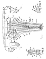
- FIGURE 1 is fragmentary top plan view of a bucket edge with a series of digging tooth assemblies, embodying principals of the present invention, attached thereto;
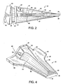
- FIGURE 2 is a sectional view taken along line 2 - 2 of FIG. 1 ;
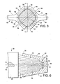
- FIGURE 3 is a sectional view taken along line 3 - 3 of FIG. 1 ;
- FIGURE 4 is a perspective view of a digging tooth embodying principals of the present invention.
- FIGURE 5 is a side elevational view of one form of retaining apparatus used in combination with the present invention.
- FIGURE 6 is a fragmentary sectional view taken along line 6 - 6 of FIG. 3 ;
- FIGURE 7 is a sectional view taken along line 7 - 7 of FIG. 1 ;
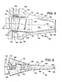
- FIGURE 8 is a top plan view of an alternative form of the present invention.
- FIGURE 9 is a side view of that embodiment of the invention illustrated in FIG. 8 ;
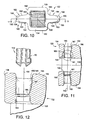
- FIGURE 10 is a rear view of that embodiment of the invention illustrated in FIG. 8 ;
- FIGURE 11 is a sectional view taken along line 11 - 11 of FIG. 10 ;
- FIGURE 12 is an enlarged sectional view of the encircled area of FIG. 11 showing one form of retaining apparatus for insertion into operable association with the digging tooth;
- FIGURE 13 is an enlarged view similar to FIG. 12 showing the retaining apparatus inserted further into operable association with the digging tooth
- FIGURE 14 is an enlarged view similar to FIGS. 12 and 13 showing progressive insertion of the retaining apparatus into further operable association with the digging tooth;
- FIGURE 15 is an enlarged view of a corresponding but opposite side of the digging tooth following the retaining apparatus being arranged in operable association with the digging tooth;
- FIGURE 16 is a fragmentary side elevational view of the digging tooth illustrated in FIG. 8 and having the retaining apparatus arranged in operable association therewith;
- FIGURE 17 is a top plan view of an example useful for understanding the present invention.
- FIGURE 18 is a rear view of that example illustrated in FIG. 17 ;
- FIGURE 19 is a side elevational view ofyet another example .
- FIGURE 20 is a rear view of that example illustrated in FIG. 19 ;
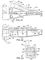
- FIGURE 21 is a side elevational view of still another example ;
- FIGURE 22 is a top plan view of that example illustrated in FIG. 22 ;
- FIGURE 23 is a sectional view taken along line 23 - 23 of FIG. 21 ;
- FIGURE 24 is a top plan view of another embodiment of the present invention.
- FIGURE 25 is a sectional view taken along line 25 - 25 of FIG. 24 ;
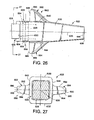
- FIGURE 26 is a top plan view of another example ;
- FIGURE 27 is a sectional view taken along line 27 - 27 of FIG. 26 ;
- FIGURE 28 is a top plan view of another example ;
- FIGURE 29 is a sectional view taken along line 29 - 29 of FIG. 28 ;
- FIGURE 30 is a fragmentary side elavational view of that example illustrated in FIG. 28 ;
- FIGURE 31 is a perspective view of another form of the present invention.
- FIGURE 32 is a side elevational view of that embodiment of the invention illustrated in FIG. 31 .
- a ground engaging implement such as a bucket or the like, generally indicated by numeral 10, with a series of digging tooth assemblies 12 arranged in side-by-side relation relative to each other.
- Bucket 10 is of the type commonly arranged in combination with a backhoe, front loader, excavator or related earth working implement.
- bucket 10 includes a base edge or lip 14 extending across and typically welded to the remainder of the bucket 10.
- the leading bucket edge or lip 14 is usually of one-piece construction and can have varying lengths depending upon the particular application.
- each digging tooth assembly 12 extends forward from the bucket edge 14 to fracture, penetrate, and trench the ground material in advance of and thereby promote penetration of the bucket edge 14 into the ground.
- the majority of tooth assemblies 12 are of similar construction relative to each other. Accordingly, only one digging tooth assembly 12 will be discussed in detail.
- each digging tooth assembly 12 is preferably configured as a two-part system including an adapter 20 and a replaceable point or digging tooth 22.
- the adapter 20 and digging tooth 22 are releasably maintained in operable combination relative to each other by a suitable retaining apparatus 24.
- Adapter 20 is preferably of one-piece construction and has an elongated free ended configuration. More specifically, adapter 20 includes a base portion 26 and a nose portion 28. Base portion 26 is configured for suitable attachment to the bucket edge 14 with nose portion 28 extending forward therefrom. It is not uncommon in the industry to attach the adapter base portion 26 to the bucket edge 14 as by welding. As shown in FIG. 3 , the adapter nose portion 28 defines a throughbore or hole 29 provided toward one end thereof.
- Each digging tooth 22 has an elongated generally wedge shaped configuration including a first or upper surface 30 and a second or lower surface 32 ( FIG. 2 ). As shown in FIG. 2 , the upper surface 30 of tooth 22 extends forward and downwardly from a rear or mounting end 34 toward the forward end 36 of the tooth 22. The lower surface 32 of tooth 22 extends forward and upwardly from the rear mounting end 34 toward the forward end 36 of the tooth 22. In the illustrated embodiment, the rear mounting end 34 and forward end 36 of tooth 22 are axially aligned along a longitudinal centerline 38 of the tooth 22.
- the ground engaging or digging tooth 22 further includes a pair of laterally spaced side surfaces 42 and 44. Moreover, and as shown in FIGS. 1 and 4 , each digging tooth 22 defines a cutting or ground penetrating edge 46 extending transversely across the forward end 36 of the tooth 22.
- a blind cavity or socket 50 is defined by and opens to the rear end 34 of each ground engaging tooth 22. In a preferred embodiment, the cavity or socket 50, is substantially centered on the longitudinal centerline 38 of the tooth 22.
- the conjuncture between the adapter 20 and the digging tooth 22 can take a myriad of different forms without detracting from the spirit and scope of the invention and, in cross-section, has a closed margin 52 extending thereabout.
- the cross-section of the blind cavity 50 on tooth 22 generally corresponds to the cross-section of the nose-portion 28 of the adapter 20.
- a lengthwise portion of the adapter nose portion 28 longitudinally extends and is accommodated within the blind cavity 50 on the digging tooth 22.
- the adapter nose portion 28 and the blind cavity 50 defined by the tooth preferably have a unique configuration.
- the blind cavity 50 opening to the rear end 34 of tooth 22 has a cross-sectional profile having a generally rhombus-like configuration for a major portion of the longitudinal length thereof
- the adapter nose portion 28 has a corresponding rhombus-like cross-sectional configuration for a majority of its length.
- the adapter 20 and digging tooth 22 are preferably designed to accommodate either a vertically disposed or diagonal pin retaining system.
- Digging tooth 22 includes a throughbore which, in the illustrated embodiment, includes a pair of openings or holes 54, 56 positioned to cooperate with the opening or bore 29 in the adapter nose portion 28 and axially aligned along a diagonal axis 58.
- axis 58 extends at an angle ranging between about 25 ° and about 65 ° relative to the edge 46 transversely extending across the forward or first end 36 of the digging tooth 22. In a most preferred form, axis 58 extends at an angle of about 45 ° relative to the edge 46 transversely extending across the first end 36 of the digging tooth 22.
- axis 58 extends generally normal to an upper slanted surface on the adapter nose portion 28 and generally perpendicular to the longitudinal axis or centerline 38 ( FIG. 1 ) of the digging tooth 22.
- apparatus 24 for maintaining the adapter 20 and digging tooth 22 in operable combination can also take various forms without detracting or departing from the spirt and scope of the present invention.
- apparatus 24 includes an elongated flex-pin structure 60.
- the flex-pin retainer 60 is typically elliptical in cross-section and, as shown in FIG. 5 , includes a first pin half or elongate member 62 and a second half or elongate member 64 joined in a conventional manner by a hard yet compressible elastomer 66 secured therebetween.
- the pin half 62 has a beveled end portion 65 at opposite ends thereof .
- the flex-pin retainer 60 presents a blunt surface at opposed ends and to the hammer or other tool (not shown) used to drive the flex-pin 60 through either opening 54 and 56 ( FIG. 3 ) and into the bore 29 in the adapter.
- the exterior diameter of pin half 62 is abruptly reduced below the beveled end portion to create a radial shoulder 67 at each end of the flex-pin 60.
- the lengthwise distance between the radial shoulders 67 is sized to releasably retain the pin 60 within the bore 29 in the adapter 20 while the remaining lengthwise portion of the pin 60 will abut against the tooth 22 at the interior edge of the openings 54, 56.
- the digging tooth 22 is furthermore provided with stabilizing structure 70 arranged within and toward the closed end of the blind cavity 50.
- stabilizing structure 70 includes a pair of spaced, generally flat stabilizing lands 72 and 74 which, after the ground engaging tooth 22 is slidably arranged in operable combination with the adapter nose portion 28, are adapted to cooperate with complimentary structure on the adapter nose portion 28 whereby adding stability to the digging tooth 22 during a digging operation.
- the digging tooth 22 further includes wing structure 80 preferably including first and second wings 82 and 84 projecting laterally outwardly from the sides 42 and 44, respectively, of the digging tooth 22.
- the purpose of the wing structure 80 is multifold. That is, wing structure 80 serves to shield and protect ground engaging components disposed rearwardly of the rear end 34 of the digging tooth 22 against wear.
- the wing structure 80 serves to gradually and significantly widen the ground penetration zone provided by each digging tooth assembly 12.
- wing structure 80 enhances the penetration capability of the bucket edge 14 into the ground while concomitantly reducing the energy required to effect such ends.
- the cumulative effect of the wing structure 80 on the digging teeth 22 extending laterally across the bucket edge 14 can enhance bucket payload.
- wing structure 80 including wings 82, 84 is formed integral with the reminder of the digging tooth 22.
- each wing 82, 84 is designed such that a dynamic or longitudinally swept back configuration is provided to the tooth 22.
- each wing 82, 84 extending laterally outward from the side surfaces 42, 44, respectively has a rear laterally widened portion 86, a laterally narrowed forward or front portion 88, and an outer edge 90 extending therebetween
- each wing 82, 84 has a longitudinally swept back design for a major portion of the length of the tooth 22 between the front and rear ends 36 and 34, respectively, thereof. That is, in one form, each wing 82, 84 is designed to have a longitudinally swept back configuration for more than one half the overall length of the tooth such that ground engaging or digging tooth 22 of assembly 12 has a gradually widening ground penetration zone for initially fracturing the ground engaged by the tooth in advance of the bucket edge 14.
- the wings 82, 84 longitudinally extend for a major lengthwise portion along opposed side surfaces 42, 44, respectively, of the digging tooth 22, it should be appreciated the wings 82, 84 could have a length less than that shown while extending between the rear and forward ends 34, 36 of the tooth 22 without detracting or departing from the spirit and scope of the invention.
- each wing 82, 84 can also have different designs along the length thereof without detracting or departing from the spirit and scope of this invention.
- edge 90 has a step-like profiled configuration between opposed ends of each wing 82, 84.
- the rear portion of the edge 90 of each wing 82, 84 preferably extends in generally parallel relation to the centerline axis 38 of the digging tooth 22 for a longitudinal distance ranging between about one-third and one-half the overall distance between the rear end 36 and forward end 34 of the digging tooth 22. Thereafter, the outer wing edge 90 laterally converges toward the central axis 38 of the tooth 22.
- each wing 82, 84 extends in generally parallel relation relative to the side surface of the tooth 22 from which the wing laterally extends.
- the wing edges of laterally adjacent digging teeth extending from the leading edge of the bucket diverge relative to each other.
- the profile on the edges of wings 82, 84 preferably provide the tooth 22 with the swept back or dynamic design promoting movement of the winged tooth 22 through the ground.
- each wing 82, 84 extending laterally from a respective side surface on the digging tooth 22, has a generally planar first or upper surface 92 and a generally planar second or lower surface 92 extending toward the outer edge 90.
- the upper and lower surfaces 92 and 94, respectively, of each wing or projection 82, 84 is disposed between and in other than planar relationship relative to the upper and lower surfaces 30, 32, respectively on the digging tooth 22.
- each projection 82, 84 extends laterally outward from an area on the respective side surface of the tooth 22 disposed proximately midway between the upper and lower surfaces 30, 32, respectively, of tooth 22.
- each wing 82, 84 is preferably designed to promote ground penetration of the tooth 22. That is, the lateral extreme of each wing 82, 84 is preferably provided with first and second edges 96 and 98 ( FIG. 3 ), respectively, angling or converging relative to each other to provide the remaining portion of the edge 90 of each wing 82, 84 with a sharpened or knife-like configuration whereby promoting the ability of the wings 82, 84 to slice, penetrate and fracture the ground ahead of the leading bucket edge 14.
- FIGS. 8 through 16 illustrate an alternative form of digging tooth which can readily be used in combination with the more conventional two-part digging tooth systems.
- This alternative form of digging tooth is designated generally by reference numeral 122 in FIGS. 8 through 16 .
- the elements of this alternative digging tooth that are functionally analogous to those components discussed above regarding digging tooth 22 are designated by reference numerals identical to those listed above with the exception this embodiment uses reference numerals in the 100 series.
- the digging tooth 122 is configured for use with an adapter 120 with a nose portion 128 extending forward from an edge of an implement or bucket, as described above, and having a well known and widely used generally rectangular cross-sectional configuration. That is, the adapter 120 further includes a conventional mounting portion (not shown) configured to suitably attach the adapter 120 to the edge of the bucket or the like.
- Digging tooth 122 has an elongated generally wedge shaped configuration including a first or upper surface 130 and a second or lower surface 132 ( FIG. 9 ). As shown in FIG. 9 , the upper surface 130 of tooth 122 extends forward and downwardly from a rear or mounting end 134 toward the forward end 136 of the tooth 122. The lower surface 132 of tooth 122 extends forward and upwardly from the rear mounting end 134 toward the forward end 136 of the tooth 22. In the embodiment illustrated in FIG. 7 , the rear mounting end 134 and forward end 136 of tooth 122 are axially aligned along a longitudinal centerline 138 of the tooth 122.
- the ground engaging or digging tooth 122 further includes a pair of laterally spaced side surfaces 142 and 144.
- Digging tooth 122 further includes a cutting or ground penetrating edge 146 extending transversely across the forward end 136 thereof.
- a blind cavity or socket 150 is defined by and opens to the rear end 134 of the tooth 122.
- the cavity or socket 150 defined by and opening to the rear 134 of the digging tooth 122, is substantially centered on the longitudinal centerline 138 of the tooth 122. As shown in FIG.
- the cavity or socket has a generally rectangular configuration which compliments the cross-sectional configuration of the adapter nose portion 128 whereby allowing adapter 120 and digging tooth 122 to be assembled in operable combination relative to each other, with a lengthwise portion of the adapter nose portion 128 ( FIG. 8 ) longitudinally extending and being accommodated within the blind cavity 150 on the digging tooth 122.
- tooth 122 is further provided with wing structure 180 preferably including first and second wings 182 and 184 projecting laterally outwardly from the side surfaces 142 and 144, respectively, of the digging tooth 122.
- the wing structure 180 on the digging tooth 122 serves to shield and protect ground engaging components disposed rearwardly of the rear end 134 of the digging tooth 122 against wear.
- the wing structure 180 serves to significantly widen the ground penetration zone provided by the digging tooth 122 as, thus, also serves to enhance the penetration capability of the bucket edge into the ground while concomitantly reducing the energy required to effect such ends.
- Each wing 182, 184 comprising wing structure 180 is preferably formed integral with the reminder of the digging tooth 122. Moreover, each wing 182, 184 is preferably designed and configured such that a dynamic or longitudinally swept back configuration is provided to the digging tooth 122. In the embodiment illustrated in FIG. 8 , each wing 182, 184 extends laterally outward from the respective side surface 142, 144 of the tooth 122 and has a rear laterally widened portion 186, a laterally narrowed forward or front portion 188, with an outer edge 190 extending therebetween. In the illustrated embodiment, and while having sufficient strength to serve the purpose of which it is designed, each projection or wing 182, 184 has a relatively narrow vertical width, especially toward a forward end thereof, to promote ground penetration as the tooth is driven and moves horizontally through the ground.
- each wing 182, 184 has a longitudinally swept back design for a major portion of the length of the tooth 122 between the front and rear ends 136 and 134, respectively, thereof That is, in the form shown in FIG. 8 , each wing 182, 184 is preferably designed to have a longitudinally swept back configuration for more than one half the overall length of the tooth such that the ground engaging or digging tooth 122 has a gradually widening ground penetration zone for initially fracturing the ground engaged by the tooth in advance of the bucket edge.
- the outer edge 190 of each wing 182, 184 can have different designs along the length thereof without detracting or departing from the spirit and scope of this invention.
- the outer edge 190 preferably has a step-like profiled configuration between opposed ends of each wing 182, 184.
- a rear portion of the outer edge 190 of each wing 182, 184 preferably extends in generally parallel relation to the centerline axis 138 of the digging tooth 122 for a longitudinal distance ranging between about one-third and one-half the overall distance between ends 134 and 136 of the digging tooth 122.
- the edge 190 of each wing laterally converges toward the centerline 138 of the digging tooth.
- each wing 182, 184 extends in generally parallel relation relative to the respective side surface of the tooth 122 from which the wing laterally extends.
- the wing edges on laterally adjacent digging teeth angle away from each other.
- the outer profile on the wings 182, 184 forming wing structure 180 preferably provides the digging tooth 122 with the swept back or dynamic design promoting movement of the winged tooth 22 through the ground.
- each wing 182, 184 extending laterally from a respective side surface on the digging tooth 122, has a generally planar first or upper surface 192 and a generally planar second or lower surface 194 extending toward the outer edge 190.
- the upper surface 192 of each wing 182, 184 extends in a direction generally parallel to the cutting edge 146 ( FIG. 8 ) at the forward end 136 of the digging tooth.
- the upper and lower surfaces 192 and 194, respectively, of each wing or projection 182, 184 is disposed between and in other than planar relationship relative to the upper and lower surfaces 130, 132, respectively on the digging tooth 122.
- each projection 182, 84 extends laterally outward from an area on the respective side surface of the tooth 122 disposed proximately midway between the upper and lower surfaces 130, 132, respectively, of tooth 122. That section of the outer edge 190 linearly proximate to the rear of each wing, and as shown in FIG. 10 , is preferably configured to promote the entrapment of dirt fines between the wings of laterally adjacent teeth and the bucket edge to further promote protection of the exposed portion of the bucket edge.
- each wing 182, 184 is preferably designed to promote ground penetration of the tooth 122. That is, the lateral extreme of each wing 182, 184 is preferably provided with first and second chamferred edges 196 and 198, respectively, angling or converging relative to each other to provide the remaining edge portion of each wing 182, 184 with a sharpened or knife-like configuration whereby promoting the ability of the wings 182, 184 to slice, penetrate and fracture the ground of the leading bucket edge 14.
- the conventional adapter 120 illustrated in combination with digging tooth 122 further defines a generally horizontally disposed throughbore 129 ( FIG. 8 ) for accommodating a lengthwise portion of a retaining apparatus 124 used to couple adapter 120 and tooth 122 in operable combination.
- the digging tooth 122 also has a throughbore defined by a pair of openings 154, 156 aligned along a generally horizontal axis 158 ( FIG. 8 ) extending generally normal to axis 138 and positioned to cooperate with the opening or bore 129 in the adapter to accommodate the retaining apparatus 124 passing generally horizontally therethrough.
- the wings 182, 184 preferably extend laterally outwardly from an area on the sides surfaces 142, 144 arranged proximately midway between the upper and lower surfaces 130, 132 ( FIG. 9 ) of the digging tooth
- the wings 182 and 184 on the digging tooth 122 further defines a pair of open channels 183 and 185, respectively.
- the channels 183, 185 on the wings 182, 184, respectively, each have a generally U-shape cross-sectional configuration opening to one of the upper and lower surfaces 192 and 194, respectively, and to the outer edge 190 of the respective wings 182, 184. As shown in FIGS.
- the open channels 183, 185 defined by the wing structure 180 on the digging tooth 122 are arranged in generally axial alignment relative to each other and relative to the axis 158 of the openings 154, 156 in the digging tooth 122.
- the channels 183, 185 on the wings 182, 184 are configured to cradle, support and guide the retaining apparatus 124, regardless of its particular design, when the adapter 120 and tooth 122 are to be joined in operable combination relative to each other.
- a flex-pin retainer 60 ( FIG. 5 ) for operably securing the adapter 120 and tooth 122 in operable combination relative to each other.
- the area arranged proximate to each tooth opening 154, 156 is configured to impart compression to and as the flex-pin retainer 60 is inserted into position to maintain the adapter 120 and tooth 122 in operable combination relative to each other.
- the channels 183, 185 on digging tooth 122 are mirror images of each other. Thus, a description of only channel 183 will be provided.
- each open channel 183/185 includes an elongated camming surface 187 extending from the open end of the channel, disposed adjacent to the outer edge 190 of the respective wing, and toward a protrusion 189 disposed between the open end of the channel and the respective bore or hole in the tooth 122 opening to the blind cavity 150.
- the radial protrusion 189 is disposed to radially narrow the size of the passage through which the flex-pin retainer 60 travels or passes along its path to the respective opening or bore in the side of the digging tooth 122.
- each channel 183/185 is widened at that end of the respective channel disposed proximate to the outer edge of the wing or projection.
- the tapered design of each channel furthermore prevents solids from being driven inward toward the retaining apparatus 124 regardless of the form used.
- the tapered design of each channel allows solids entrapped in the channel from being quickly dislodged therefrom when the retaining apparatus is driven in an outward direction so as to provide a self-cleaning function.
- the tapered design of each channel yield further maneuverability as the retaining apparatus is inserted into and removed from operable association with the adapter and tooth. This advantage is of particular importance when considering the angularity associated with corner digging tooth arrangements.
- the camming surface 187 of the respective channel 183/185 narrows the retaining pin passage leading to the respective bore in the digging tooth 122. Moreover, as the pin 60 passes along the channeled passage, the camming surface 187 engages with the beveled or chamferred end portion 65 of the flex-pin 60 thereby causing pin half 62 to move toward pin half 64 as through compression of the elastomer material 66 thereby reducing the width of the elliptical retainer 60.
- the beveled or chamferred end portion 65 of the flex-pin retainer 60 engages and moves past the radial protrusion 189.
- the radial protrusion 189 causes further radially directed inward movement of the pin half 62 toward pin half 64 and further compression of the elastomer material 66 whereby furthermore reducing the width of the flex-pin 60.
- reducing the width of the flex-pin 60 facilitates entry of the end of the flex-pin 60 into the bore 129 of the adapter 120.
- the area arranged proximate to each tooth opening 154, 156 ( FIG. 11 ) is also configured to inhibit inadvertent axial shifting of the retaining apparatus 124 relative to the adapter 120 and digging tooth 122 following insertion of the retaining apparatus 124 into operative combination therewith.
- FIG. 15 shows the flex-pin 60 as being fully inserted into operative combination with the adapter 120 and digging tooth 122.
- portion of the radial protrusion 189 extending toward the opening or hole 154, 156 in the side surface of the tooth 122 is configured with a slanting surface 191 disposed linearly from the chamferred or beveled end portion 65 on the flex-pin retaining apparatus 60 following the flex-pin 60 being fully inserted into operative combination with the adapter 120 and digging tooth 122.
- the chamferred or beveled end portion 65 on the flex-pin retaining apparatus 60 will abut against the surface 191 on the radial protrusion 189 which will thereafter halt further inadvertent linear movement or displacement of the flex-pin 60 relative to either adapter 120 or digging tooth 122.
- FIGS. 8 and 16 illustrate how the channels 183, 185 protect the free ends of the retaining apparatus 124 extending beyond opposed sides surfaces of the digging tooth 122. That is, configuring wing structure 180 to extend from an area proximately midway between the upper and lower surfaces 130, 132 ( FIG. 16 ) of the digging tooth 122, allows retaining apparatus 124 to be operably embedded in the respective channel of the wing in spaced relation from the wing surface 192, 194 defining the channel and which serves to deflect materials from engaging and otherwise impacting with the free ends of the retaining apparatus 124 safely cradled within the open top channels 183, 185 and, thus, out of direct contact with the materials moving therepast and thereover. Moreover, dirt fines are likely to become entrapped within each channel on the digging tooth thereby further protecting the free ends of the retaining apparatus 124 extending from opposed side surfaces of the tooth 122 from having pin dislocating influences and forces placed thereon during a digging operation.
- Each channel 183, 185 provided on the wing structure 180 preferably opens to an upper surface of a respective wing 182, 184, respectively.
- the digging tooth 122 is provided with a strengthening rib or lateral projection 193 underlying an area extending directly beneath each channel 183, 185 and which is configured to impart a minimal affect on the ability of the tooth to move horizontally through the ground.
- FIGS. 17 and 18 illustrate form of digging tooth useful for understanding the invention which can readily be used in combination with a corner adapter position.
- This form of digging tooth is designated generally by reference numeral 222 in FIGS. 17 and 18 .
- the elements of this digging tooth design that are functionally analogous to those components discussed above regarding digging tooth 22 are designated by reference numerals identical to those listed above with the exception this example uses reference numerals in the 200 series.
- digging tooth 222 is configured for use with an adapter 220 with a nose portion 228 extending forward from an edge of an implement or bucket, as described above.
- the tooth 222 is operably connected to adapter 220 through use of a conventional retaining apparatus (not shown).
- Tooth 222 has an elongated generally wedge shaped configuration having an upper surface 230 and a lower surface 232. The first or upper surface 230 downwardly slants from the rear end 234 and toward the forward end 236 of the tooth 222.
- tooth 222 is provided with a cutting edge 246 extending transversely across the forward end 236.
- the second or lower surface 232 ( FIG. 18 ) slants upward between the ends 234, 236 of the tooth 222.
- the ends 234, 236 of tooth 222 are aligned along a central axis 238.
- the ground engaging or digging tooth 222 further includes a pair of laterally spaced side surfaces 242 and 244.
- Digging tooth 222 further includes a cutting or ground penetrating edge 246 extending transversely across the forward end 236 thereof.
- a blind cavity or socket 250 is defined by and opens to a rear end 234 of the tooth 222.
- the cavity 250 defined by and opening to the rear 234 of the digging tooth 222, has a cross-sectional configuration which compliments the cross-sectional configuration of the nose portion 228 of adapter 220 whereby allowing adapter 220 and digging tooth 222 to be assembled in operable combination. That is, the cavity 250 defined by tooth 222 can have a generally rhombus-like cross-sectional configuration, a generally rectangular cross-sectional configuration, or any other suitable cross-sectional configuration.
- wing structure 280 is provided on the digging or ground engaging tooth 222.
- wing structure 280 includes a single wing 284 laterally extending outwardly from the side surface 244 of the tooth 222 proximately midway between the upper and lower surfaces 230 and 232, respectively.
- the wing structure 280 serves to shield and protect ground engaging components disposed rearwardly of the rear end 234 of the digging tooth 222 against wear.
- wing 284 serves to significantly widen the ground penetration zone provided by the digging tooth 222. Widening the penetration zone for the digging tooth also serves to enhance the penetration capability of the bucket edge into the ground while concomitantly reducing the energy required to effect such ends.
- Wing 284 is preferably formed integral with the reminder of the digging tooth 222.
- the wing 284 is arranged on the tooth 222 in generally symmetrical relation relative to the central axis 238 whereby enhancing the versatility of the tooth by allowing it to be reversed about the central axis 238 and, thus, serve on either corner adapter for the bucket.
- the wing 284 has a rear laterally widened portion 286, a laterally narrowed forward or front portion 288, with an outer edge 290 extending therebetween
- the projection or wing 284 has a relatively narrow vertical dimension to promote ground penetration as the tooth moves and is driven horizontally through the ground.
- wing 284 has a longitudinally swept back design for a major portion of the length of the tooth 222 between the rear and front ends 234 and 236, respectively, thereof That is, in the form shown in FIG. 17 , wing 284 is designed to have a longitudinally swept back configuration for more than one half the overall length of the tooth so as to provide tooth 222 with a gradually widening ground penetration zone for initially fracturing the ground engaged by the tooth 222 in advance of the bucket edge.
- the outer edge 290 of wing 284 can have different designs along the length thereof. As shown in FIG. 17 , wing edge 290 has a step-like profiled configuration between opposed ends of wing 284. The rear portion of the outer edge 290 of wing 284 preferably extends in generally parallel relation to the centerline axis 238 of the digging tooth 222 for a longitudinal distance ranging between about one-third and one-half the overall distance between ends 234 and 236 of the tooth 222.
- the wing edge 290 laterally converges or angles toward the central axis 238 of the tooth, Notably, that portion of the wing edge 290 extending longitudinally along the laterally narrowed portion 288 of wing 282 extends in generally parallel relation relative to the side surface 244 of the tooth 222 from which wing 284 laterally extends.
- the preferred slanting configuration of the wing edge 290 provides tooth 222 with the swept back or dynamic design promoting movement of the winged tooth 22 through the ground.
- a rear portion of wing 284, extending laterally from side surface 244 on the digging tooth 222, has a generally planar first or upper surface 292 and a generally planar second or lower surface 294 extending toward the outer edge 290.
- the upper surface 292 of wing 284 extends in a direction generally parallel to the cutting edge 246 at the forward end 236 of the digging tooth. That section of the outer edge 290 linearly proximate to the rear of the wing 284, and as shown in FIG. 18 , is preferably configured to promote the entrapment of dirt fines between the wings of laterally adjacent teeth and the bucket edge.
- the remaining linear edge portion of wing 284 is preferably designed to promote ground penetration of the tooth 222. That is, the lateral extreme of wing 284 is preferably provided with first and second chamferred edges 296 and 298, respectively, angling or converging relative to each other to provide the remaining edge portion of the wing 284 with a sharpened or knife-like configuration whereby promoting the ability of the wing 284 to slice, penetrate and fracture the ground ahead of the leading bucket edge.
- FIGS. 19 and 20 illustrate a mining tooth designated generally by reference numeral 322 according to an example useful for understanding the invention.
- the elements of this tooth design that are functionally analogous to those components discussed above regarding tooth 22 are designated by reference numerals identical to those listed above with the exception this embodiment uses reference numerals in the 300 series.
- mining tooth 322 has an elongated generally wedge shaped configuration including an upper surface 330 and a lower surface 332.
- the upper surface 330 downwardly slants from the rear end 334 and toward the forward end 336 of the tooth 322.
- the lower surface 332 slants upward between the rear and forward ends 334 and 336, respectively.
- the tooth 332 is provided with a cutting edge 346 extending transversely across the front end of the tooth 322.
- the ends 334, 336 of the tooth are aligned along a central axis 338.
- the ground engaging or digging tooth 322 further includes a pair of laterally spaced side surfaces 342 and 344.
- a blind cavity or pocket 350 is defined by and opens to a rear end 334 of the tooth 322.
- the cavity 350 defined by and opening to the rear 334 of the digging tooth 322, has a cross-sectional configuration which compliments the cross-sectional configuration of the nose portion of an adapter whereby allowing adapter 320 and digging tooth 322 to be assembled in operable combination. That is, the cavity 350 defined by tooth 322 can have a generally rhombus-like cross-sectional configuration, a generally rectangular cross-sectional configuration, or other suitable cross-sectional configuration.
- mining tooth 322 is provided with wing structure 380.
- the wing structure 380 includes a longitudinally extending wing 384 projecting vertically from the upper surface 330 of the digging tooth 322 proximately midway between the side surfaces 342 and 344, respectively, and in a direction extending generally normal to the transverse cutting edge 346 at the front end 336 of the tooth.
- the projection or wing 384 has a relatively narrow lateral width to promote ground penetration as the tooth moves both vertically and horizontally.
- Providing the wing structure 380 on the tooth 322 is expected to extend the wear life of those wear components, i.e. wear cap, and etc., arranged in operable combination with a two-part digging tooth system of which tooth 322 is configured to serve as an integral part.
- Wing 384 of structure 380 is preferably formed integral with the reminder of the digging tooth 322.
- the wing 384 has a rear vertically widened portion 386, a vertically narrowed forward or front portion 388, with an outer edge 390 extending therebetween.
- wing 384 progressively increases in height for a major portion of the length of the tooth 322 between the front and rear ends 336 and 334, respectively, thereof. That is, in the form shown in FIG. 19 , wing 384 increases in height for more than one half the overall length of the tooth 322.
- the linear edge portion 390 of wing 384 is preferably designed to promote ground penetration of the tooth 322. That is, the vertical extreme of wing 384 is preferably provided with first and second chamferred edges 396 and 398, respectively, angling or converging relative to each other to provide the edge portion of the wing 384 with a sharpened or knife-like configuration whereby promoting the ability of the wing 384 to slice, penetrate and fracture the ground as the tooth 322 is moved both horizontally and vertically.
- FIGS. 21, 22 and 23 illustrate a two-part tooth assembly including still another form of tooth designed to shield and/or protect a wear component arranged rearwardly thereof.
- the tooth is designed to enhance wear characteristics of a ground engaging portion of a sidewall 11 on a bucket 10 or the like.
- the tooth illustrated in FIGS. 21, 22 and 23 is designated generally by reference numeral 422.
- the elements of this digging tooth design that are functionally analogous to those components discussed above regarding digging tooth 22 are designated by reference numerals identical to those listed above with the exception this example uses reference numerals in the 400 series.
- tooth 422 is configured for use with a corner adapter 420 having a nose portion 428 extending forward from an edge 14 of an implement or bucket 10, as described above.
- the digging tooth 422 is operably connected to the adapter 420 through use of a conventional retaining apparatus 424.
- Digging tooth 422 has an elongated generally wedge shaped configuration including a first or upper surface 430 and a second or lower surface 432.
- the upper surface 430 downwardly slants from the rear end 434 and toward the forward end 436 of the tooth 422.
- the lower surface 432 of tooth 422 is inclined upward between the rear and forward ends 434 and 436, respectively.
- the ends 434, 436 of the tooth are aligned along a central axis 43 8.
- tooth 422 further includes laterally spaced side surfaces 442 and 444.
- tooth 422 further includes a cutting or ground penetrating edge 446 extending transversely across the forward end 436 thereof.
- a blind cavity or pocket 450 is defined by and opens to a rear end 434 of the tooth 422.
- the cavity 450 defined by and opening to the rear 434 of the digging tooth 422, has a cross-sectional configuration which compliments the cross-sectional configuration of the nose portion of adapter whereby allowing adapter 420 and digging tooth 422 to be assembled in operable combination. That is, the cavity 450 defined by tooth 422 can have a generally rhombus-like cross-sectional configuration, a generally rectangular cross-sectional configuration, or other suitably cross-sectional configuration.
- tooth 422 includes a longitudinally extending projection 484 extending vertically from the upper surface 430 of the digging tooth 422 in a direction extending generally normal to the edge 446 at the forward end 436 of the tooth 422.
- the projection 484 is laterally offset relative to the upper surface 430 of the tooth 422 such that the projection 484 is disposed closer to side surface 442 than it is relative to side surface 444.
- providing the projection 484 proximate to the side surface 442 on the digging tooth serves to shield and, thus, extend the wear life of the wear component, i.e. bucket side wall 11, arranged in rearwardly of the digging tooth 422 on the two-part digging tooth system.
- Projection 484 is preferably formed integral with the reminder of the tooth 422.
- projection 484 has a rear vertically widened portion 486, a vertically narrowed forward or front portion 488, with an outer edge 490 extending therebetween.
- projection 484 progressively increases in height for a major portion of the length of the tooth 422 between the front and rear ends 436 and 434, respectively, thereof.
- projection 484 continues to increase in height for more than one half the overall length of the tooth 422.
- the projection 484 has a relatively narrow lateral width to promote ground penetration as the tooth moves both vertically and horizontally.
- the linear edge portion of the projection 484 is preferably designed to promote ground penetration of the tooth 422. That is, the extreme vertical edge of the projection 484 is preferably provided with first and second chamferred edges 496 and 498, respectively, angling or converging relative to each other to provide the edge portion of the projection 484 with a sharpened or knife-like configuration whereby promoting the ability of the projection 484 to slice, penetrate and fracture the ground as the tooth 422 is moved both horizontally and vertically through the ground during an operation.
- FIGS. 24 and 25 illustrate another form of tooth forming part of a two-part digging tooth system.
- This alternative form of digging tooth is designated generally by reference numeral 522 in FIGS. 24 and 25 .
- the elements of this alternative digging tooth that are functionally analogous to those components discussed above regarding digging tooth 22 are designated by reference numerals identical to those listed above regarding tooth 22 with the exception this embodiment uses reference numerals in the 500 series.
- the digging tooth 522 is configured for use with an adapter 520 with a nose portion 528 extending forward from an edge of an implement or bucket, as described above.
- the digging tooth 522 is operably connected to the adapter 520 through use of a conventional retaining apparatus 524.
- Digging tooth 522 has an elongated generally wedge shaped configuration including an upper surface 530 and a lower surface 532.
- the upper surface 530 slants from the rear end 534 and toward the forward end 536 of the tooth 522.
- the lower surface 532 is slants upward from the rear end 534 and toward the forward end 536 of the tooth 522.
- the ends 534, 536 of the tooth are aligned along a central axis 538.
- the ground engaging or digging tooth 522 further includes a pair of laterally spaced side surfaces 542 and 544.
- Digging tooth 522 further includes a cutting or ground penetrating edge 546 extending transversely across the forward end 536 thereof.
- a blind cavity or socket 550 is defined by and opens to a rear end 534 of the tooth 522.
- the cavity 550 defined by and opening to the rear 534 of the tooth 522, has a cross-sectional configuration which compliments the cross-sectional configuration of the nose portion of adapter 520 whereby allowing adapter 520 and digging tooth 522 to be assembled in operable combination. That is, the cavity 550 defined by tooth 522 can have a generally rhombus-like cross-sectional configuration, a generally rectangular cross-sectional configuration, or any other suitable cross-sectional configuration without detracting or departing from the scope of the invention.
- tooth 522 further includes wing structure 580 including first and second wing structures or lateral projections 582 and 584 extending laterally outwardly from the side surfaces 542 and 544, respectively, of the digging tooth 522 proximately midway between the upper and lower surfaces 530 and 532, respectively.
- the wing structure 580 including the projections 582, 584 serve to shield and protect ground engaging components disposed rearwardly of the rear end 536 of the digging tooth 522 against wear.
- wing structure 580 serves to significantly widen the ground penetration zone provided by the digging tooth 522. Widening the penetration zone for the tooth also enhances ground penetration capability of the bucket edge while concomitantly reducing the energy required to effect such ends.
- Each wing or projection 582, 584 is comprised of at least two longitudinally spaced sections. That is, wing 582 includes two laterally extending sections 582A and 582B disposed to the same side of the central axis relative to each other and preferably disposed in fore-and-aft and longitudinally spaced relation relative to each other. Similarly, wing 584 includes two laterally extending sections 584A and 584B preferably disposed in fore-and-aft and longitudinally spaced relation relative to each other. The fore-and-aft sections of each wing or lateral projection 582, 584 are preferably formed integral with the reminder of the digging tooth 522. In the embodiment illustrated in FIG.
- each wing 582, 584 are mirror images of each other. Accordingly, only the fore-and-aft longitudinally spaced projections or sections 582A and 582B comprising wing 582 will be discussed in detail.
- Sections 582A and 582B of wing 582 extends laterally outward from the side surface 542 of tooth 522 proximately mid-distance between the upper and lower surfaces 530 and 532 of the digging tooth 522.
- each projection or wing section 582A and 582B comprising wing 582 has a relatively narrow vertical width, especially toward a forward end thereof, to promote ground penetration as the tooth is driven and moves horizontally through the ground.
- each rearwardly disposed wing section 582B of the wing structure 580 has a laterally widened portion 586B laterally extending from the side surface 542 of tooth a greater lateral width than does a laterally narrowed portion 586A of the forward disposed wing section 582A of the same wing structure.
- Each section 582A and 582B on wing 582 has a longitudinally extending outer edge portion 590A and 590B, respectively.
- the cumulative width and effect of the sections 582A and 582B is intended to be and is equivalent to the lateral width of the comparable wing 182 on the above described digging tooth embodiment illustrated in FIGS. 8 through 12 .
- the cumulative width and effect of the wing sections 582A and 582B of wing 582 along with the cumulative width and effect of the wing sections 584A and 584B ofwing 584 is intended to be and is equivalent to the cumulative lateral width of the comparable wings 182 and 184 on the above described digging tooth embodiment illustrated in FIGS. 8 through 12 .
- the outer edge portions 590A and 590B associated with each wing section 582A and 582B of a respective wing 582 can have different designs along the length thereof without detracting or departing from the scope of this invention.
- the outer edge portion 590A of wing section 582A preferably extends a lesser lateral distance away from the central axis 538 of the digging tooth 522 than does the outer edge portion 590 B of wing section 582B.
- the outer edge portion 590A of wing section 582A extends in generally parallel relation to the centerline axis 538 of the digging tooth 522 for a longitudinal distance ranging between about one-third and one-half the overall distance between ends 534 and 536 of the digging tooth 122. It will be appreciated, however, the outer edge portion 590B of wing section 582B could be configured with a swept back design without detracting or departing from the scope of the present invention.
- the rear of the outer edge portion 590B of wing section 582B preferably extends in generally parallel relation to the centerline axis 538 of the digging tooth 522 for a longitudinal distance ranging between about one-third and one-half the overall distance between ends 534 and 536 of the digging tooth 522.
- the outer edge portion 590B thereafter laterally converges or angles toward the respective side surface of the tooth 522 from which wing section 583B laterally extends.
- Other designs or profiles can equally apply, however, to the rear wing section on opposed sides of the tooth 522 without departing or detracting from the scope of the present invention.
- each wing 582, 584 extending outwardly from a respective side surface on the tooth 522, has a generally planar upper surface 592 extending toward the outer edge portion 590B.
- the upper surface 592 of the each wing extends in a direction extending generally parallel to the edge 546 at the forward end 536 of the digging tooth.
- that lengthwise section of the outer edge portion 590B of wing section 582B linearly proximate to the rear of wing 582 is preferably configured to promote the entrapment of dirt fines between the wing edges of laterally adjacent teeth and the bucket edge.
- each rearwardly disposed wing section of the wings 582, 584 is preferably designed to promote ground penetration of the tooth 522. That is, the reminder of the extreme of each rearwradly disposed wing section of each wing structure 580 is preferably provided with first and second chamferred edges similar to the edges 596 and 598.
- the outer edge portion 590A on each forward wing section of wing structure an likewise have angularly converging edges to provide the forward disposed sections of the wing structure 580 with a sharpened or knife-like configuration whereby promoting the ability of the wing structure 580 to slice, penetrate and fracture the ground ahead of the leading bucket edge.
- the rearwardly disposed wing sections 582B and 584B of wings pr projections 582 and 584 extend laterally outwardly from an area on the sides surfaces 542, 544 arranged proximately midway between the upper and lower surfaces 530, 532 of the digging tooth
- the rearwardly disposed wing sections 582B and 584B on the digging tooth 522 further defines a pair of open top, channels 583 and 585 substantially similar to those channels 183 and 185 discussed above. Accordingly, no further details need be provided for a proper and complete understanding thereof.
- the digging tooth 522 can be configured to effect compression of a flex-pin type retaining apparatus used to releasably secure the adapter 520 and digging tooth 522 together as discussed in detail above.
- the structure for effecting compression of a flex-pin type retaining apparatus can be substantially similar to the structure discussed above with respect to tooth 122 and, thus, no further details need be provided for both a full and complete understanding thereof
- the digging tooth 522 can be configured to inhibit inadvertent lateral shifting of the retaining apparatus.
- the structure for inhibiting inadvertent lateral shifting of the retaining apparatus can be substantially similar to the structure discussed above with respect to tooth 122 and, thus, no further details need be provided for both a full and complete understanding thereof.
- FIGS. 26 and 27 illustrate another example of tooth forming part of a two-part digging tooth system useful for understanding the invention.
- This form of digging tooth is designated generally by reference numeral 622 in FIGS. 26 and 27 .
- the elements of this digging tooth that are functionally analogous to those components discussed above regarding digging tooth 22 are designated by reference numerals identical to those listed above regarding tooth 22 with the exception this embodiment uses reference numerals in the 600 series.
- the digging tooth 622 is configured for use with an adapter 620 with a nose portion 628 extending forward from an edge of an implement or bucket, as described above.
- the digging tooth 622 is operably connected to the adapter 520 through use of a conventional retaining apparatus 624 which passes through bores 654, 656 in the tooth 622 and through a bore 629 in the adapter 620.
- the bores 654, 656 in the tooth 622 define an axis 658.
- Digging tooth 622 has an elongated generally wedge shaped configuration including an upper surface 630 and a lower surface 632.
- the upper surface 630 slants from the rear end 634 and toward the forward end 636 of the tooth 622.
- the lower surface 632 is slants upward from the rear end 634 and toward the forward end 636 of the tooth 622.
- the ends 634, 636 of the tooth are aligned along a central axis 638.
- the ground engaging or digging tooth 622 further includes a pair of laterally spaced side surfaces 642 and 644.
- Digging tooth 622 further includes a cutting or ground penetrating edge 646 extending transversely across the forward end 636 thereof.
- a blind cavity or socket 650 is defined by and opens to a rear end 634 of the tooth 622.
- the cavity 650 defined by and opening to the rear 634 of the tooth 622, has a cross-sectional configuration which compliments the cross-sectional configuration of the nose portion of adapter 620 whereby allowing adapter 620 and digging tooth 622 to be assembled in operable combination. That is, the cavity 650 defined by tooth 622 can have a generally rhombus-like cross-sectional configuration, a generally rectangular cross-sectional configuration, or any other suitable cross-sectional configuration.
- tooth 622 further includes wing structure 680 including-first and second wing structures or lateral projections 682 and 684 extending laterally outwardly from the side surfaces 642 and 644, respectively, of and formed integral with the digging tooth 622.
- the wing structures or lateral projections 682 and 684, respectively, comprising the wing structure 680 have a laterally widened rear portion 686 serving to shield and protect ground engaging components disposed rearwardly of the rear of the digging tooth 622. Widening the penetration zone for the digging tooth also enhances ground penetration capability of the bucket edge while concomitantly reducing the energy required to effect such ends.
- the wing or projection 682 has upper and lower generally planar and horizontally disposed surfaces 692 and 694, respectively, extending from the side surface 642 of the digging tooth 622.and toward the outer edge 690.
- the wing or projection 684 has upper and lower generally planar and horizontally disposed surfaces 692 and 694, respectively, extending from the side surface 644 of the digging tooth 622 and toward the outer edge 690.
- the outer edge 690 extends forward from the laterally widened portion 686 on each projection 682, 684 and converges toward the central axis 638 of the digging tooth whereby providing the digging tooth with a progressively widening ground penetration zone for facilitating ground penetration of the bucket edge.
- a major longitudinal length of the outer edge 690 provided on each extension or projection 682, 684 is preferably chamferred to enhance digging tooth penetration as it is forcibly driven through the ground.
- each projection 682, 684 has a rear edge 685.
- the rear edge 685 of each lateral projection 682, 684 is disposed forward of the axis 658 defined by the bore 654, 656 in the digging tooth 622.
- FIGS. 28, 29 and 30 illustrate still another form of tooth forming part of a two-part digging tooth system useful for understanding the invention.
- This form of digging tooth is designated generally by reference numeral 722 in FIGS. 28 through 30 .
- the elements of this digging tooth that are functionally analogous to those components discussed above regarding digging tooth 22 are designated by reference numerals identical to those listed above regarding tooth 22 with the exception this example uses reference numerals in the 700 series.
- digging tooth 722 is configured for use with an adapter 720 having a nose portion 728 extending forward from an edge of an implement or bucket, as described above.
- the digging tooth 722 is operably connected to the adapter 720 through use of a conventional retaining apparatus 724 which passes through bores 754, 756 in the tooth 722 and through a bore 729 in the adapter 720.
- the bores 754, 756 in the tooth 722 define an axis 758.
- Digging tooth 722 has an elongated generally wedge shaped configuration including an upper surface 730 and a lower surface 732.
- the upper surface 730 slants from the rear end 734 and toward the forward end 736 of the tooth 722.
- the lower surface 732 slants upward from the rear end 734 and toward the forward end 736 of the tooth 722.
- the ends 734, 736 of the tooth are aligned along a central axis 738.
- the ground engaging or digging tooth 722 further includes a pair of laterally spaced side surfaces 742 and 744.
- Digging tooth 722 further includes a cutting or ground penetrating edge 746 extending transversely across the forward end 736 thereof.
- a blind cavity or socket 750 is defined by and opens to a rear end 734 of the tooth 722.
- the cavity 750 defined by and opening to the rear 734 of the tooth 722, has a cross-sectional configuration which compliments the cross-sectional configuration of the nose portion of adapter 720 whereby allowing adapter 720 and digging tooth 722 to be assembled in operable combination. That is, the cavity 750 defined by tooth 722 can have a generally rhombus-like cross-sectional configuration, a generally rectangular cross-sectional configuration, or any other suitable cross-sectional configuration.
- tooth 722 further includes wing structure 780 including first and second wing structures or lateral projections 782 and 784 extending laterally outwardly from the side surfaces 742 and 744, respectively, of and formed integral with the digging tooth 722.
- wing structures or lateral projections 782 and 784 respectively, comprising the wing structure 680 widening the penetration zone for the digging tooth, enhance ground penetration capability of the bucket edge while concomitantly protecting the cutting edge of the implement against wear.
- each projection 782, 784 extends forward from the rear 734 of the digging tooth and has a front or forward edge 785.
- the forward edge 785 of each lateral projection 782, 784 is disposed rearward of the axis 758 defined by the bore 754, 756 in the digging tooth 722.
- FIGS. 31 and 32 illustrate a one-piece or unitary digging tooth.
- This alternative form of digging tooth is designated generally by reference numeral 822 in FIGS. 31 and 32 .
- the elements of this alternative digging tooth that are functionally analogous to those components discussed above regarding digging tooth 22 are designated by reference numerals identical to those listed above regarding tooth 22 with the exception this embodiment uses reference numerals in the 800 series.
- digging tooth 822 includes an adapter portion 820A and a digging tooth portion 822A formed as a single piece.
- the adapter portion 820A of digging tooth 822 is configured to allow for attachment of the digging tooth 822 to the leading edge of the bucket or lip just as adapter 20 was attached to the bucket or lip.
- the digging tooth portion 822A of digging tooth 822 has an elongated generally wedge shaped configuration including an upper surface 830 and a lower surface 832.
- the upper surface 830 slants from the rear end 834 of the digging tooth portion 822A and toward the forward end 836 of the tooth portion 822A.
- the lower surface 832 slants upward from the rear end 834 and toward the forward end 836 of the tooth 822.
- the ends 834, 836 as well as adapter portion 820A are all aligned along a central axis 838.
- the digging tooth portion 822A of the ground engaging or digging tooth 822 further includes a pair of laterally spaced side surfaces 842 and 844.
- Digging tooth 822 further includes a cutting or ground penetrating edge 846 extending transversely across the forward end 836 thereof.
- tooth 822 further includes wing structure 880 including first and second wing structures or lateral projections 882 and 884 extending laterally outwardly from the side surfaces 842 and 844, respectively, of and formed integral with the digging tooth portion 820A.
- wing structures or lateral projections 882 and 884 respectively, comprising the wing structure 880 widen the penetration zone for the digging tooth, enhance ground penetration capability of the bucket edge while concomitantly protecting the cutting edge of the implement against wear.
- a lateral spacing of about 0.5 inches to about 0.75 inches is preferably provided between the outer edges of adjacent wings on laterally adjacent digging teeth.
- a fore-and-aft spacing of about 0.5 inch to about 4.0 inches is preferably provided between the rear end of the digging teeth and the forward/leading edge 14 of the bucket.
- Such spacings allow for inadvertent misalignment of the adapters relative to the bucket edge.
- Such spacing also facilitates entrapment of dirt fines between adjacent digging teeth and the leading bucket edge.
- the wing structure on each tooth can extend rearwardly beyond the rear end of the respective digging tooth and toward the leading edge of the bucket lip.
- each time a digging tooth is replaced new edge protection is afforded to the bucket lip whereby extending its useful life.
- the wing structure on the digging tooth is designed and disposed as to shield those ground engaging components disposed rearwardly of the rear edge of the digging or ground engaging tooth from wear and to promote ground penetration for the bucket. Due to the enhanced ground penetrating capabilities offered by the winged teeth, a non-beveled blade edge will readily suffice for the bucket, resulting in a more economic and stronger base edge for the bucket.
- the present invention With the present invention, almost the entire leading edge of the bucket lip is protected against wear by the wing structure on the digging teeth penetrating, fracturing and slicing the ground in advance of the bucket edge passing therethrough. Since the wing structure on the digging tooth of the present invention serve to penetrate and fracture the ground in advance of the bucket edge moving therethrough, the savings associated with either prolonging the purchase of a new cutting edge or the potential elimination of the need for costly carbide hardfacing of the bucket edge can be realized. Moreover, and in the embodiment wherein the wing structure on the digging tooth is arranged generally symmetrically about the digging tooth central axis, such design allows the teeth to be reversed or rotated about the centerline to maximize their utility.
- Those tooth embodiments defining an open channel on one of the generally planar surfaces of the wing structure provide numerous advantages especially when a flex-pin style retaining apparatus is used to couple the adapter and digging tooth in combination with each other.
- the digging tooth design having open channels facilitates flex-pin insertion by effecting compression of the flex-pin width in the range of approximately 15% to 40%. Compression of the width of the flex-pin by 15% to 40% will be specially advantageous in those commonly known situations where the holes on the digging tooth fail to align in a fore-and-aft direction with the opening or bore in the adapter receiving the flex-pin.
- the open channel on at least one of the upper or lower generally planar surfaces of the digging tooth wing serves a dual purpose. First, the channel serves as a pin holder in a relatively space constrained location. Second, the sides of the open channel serve as tool guides during installation of the retaining apparatus.
- the retaining pins for such retaining apparatus come in multiple lengths. Operators using longer retaining pins on conventional digging teeth face the definite prospect that the ends of the retaining pin will protrude from opposed sides of the digging tooth and, thus, the pin can become dislodged by the digging forces to which the pin ends are exposed. Of course, should the retainer become inadvertently or otherwise dislodged, separation and loss of the digging tooth from the two-part system is likely to result. With a preferred form of the invention, and following retainer installation, the sides of the open channels wrap about and extend at least partially along lengthwise end portions of the retainer extending from opposed sides of the tooth whereby protecting the free ends of the retaining apparatus.
- the tooth is configured to provide an additional locking feature to inhibit inadvertent linear shifting of the retainer apparatus relative to the tooth and adapter thereby guarding against inadvertent separation and loss of the digging tooth during a digging operation.
Landscapes
- Engineering & Computer Science (AREA)
- Mining & Mineral Resources (AREA)
- Civil Engineering (AREA)
- General Engineering & Computer Science (AREA)
- Structural Engineering (AREA)
- Component Parts Of Construction Machinery (AREA)
Claims (7)
- Baggerzahn (122), der eingerichtet ist, sich von einem Baggergerät (10) mit einer sich quer erstreckenden Kante nach vom zu erstrecken, wobei der Baggerzahn (122) eine Längsmittellinie (138) definiert und einen vorderen Endabschnitt (136) mit einer Schneidkante (146), die sich dort herüber erstreckt, und einen hinteren Endabschnitt (134) aufweist, der zur Anbringung an die Kante des Geräts konfiguriert ist, wobei der Baggerzahn (122) ferner eine obere und untere schräg auseinanderlaufende Oberfläche (130, 132) mit entgegengesetzten Seitenoberflächen (142, 144) dort dazwischen aufweist, und wobei der Baggerzahn (122) ferner einen Flügel (182, 184) aufweist, der von jeder Seitenoberfläche (142, 144) auf dem Zahn (122) seitlich nach außen übersteht, wobei jeder Flügel (182, 184) mit dem Rest des Baggerzahns (122) aus einem Stück geformt ist und eine obere und untere planare Oberfläche (192, 194) aufweist, wobei sich jede in eine Richtung erstreckt, die im Allgemeinen zu der Schneidkante (146) parallel verläuft, die sich über den vorderen Endabschnitt (136) des Baggerzahns (122) erstreckt, wobei die obere und untere Oberfläche (192, 194) von jedem Flügel zwischen und in einer anderen als einer planaren Beziehung bezüglich der oberen und unteren Oberfläche (130, 132) des Baggerzahns (122) angeordnet sind, und wobei jeder Flügel (182, 184) einen seitlich geweiteten hinteren Abschnitt (186), einen seitlich verengten vorderen Abschnitt (188) und eine Außenkante (190) aufweist, die sich dort dazwischen erstreckt, zum Bilden des Zahns (122) mit einer sich zunehmend ausweitenden Bodenaufrisszone, wodurch sich ein wesentlicher Verschleißschutz für die Kante des Geräts ergibt, und wobei der Baggerzahn (122) dadurch gekennzeichnet ist, dass eine Außenkante (190) von jedem Flügel (182, 184) einen hinteren Abschnitt aufweist, der sich in einer im Allgemeinen parallelen Beziehung zu der Mittellinienachse (138) des Baggerzahns (122) auf einer Längsdistanz erstreckt, die sich zwischen ungefähr einem Drittel und einer Hälfte der Gesamtdistanz zwischen dem hinteren Endabschnitt (134) und dem vorderen Endabschnitt (136) des Baggerzahns (122) bewegt, wobei die Außenkante (190) einen Abschnitt, der zu der Mittellinie (138) des Baggerzahns (122) seitlich konvergiert, und einen Abschnitt aufweist, der sich entlang des seitlich verengten Abschnitts (188) von jedem Flügel (182, 184) in einer im Allgemeinen parallelen Beziehung bezüglich der jeweiligen Seitenoberfläche (142, 144) des Baggerzahns (122) erstreckt, von der sich der Flügel (182, 184) seitlich erstreckt.
- Baggerzahn nach Anspruch 1, wobei der hintere Endabschnitt (134) davon mit einer Blindkavität (150) zum Aufnehmen und Unterbringen eines längsgerichteten Teilstücks eines Nasenabschnitts (128) eines Adapters (120) konfiguriert ist, der sich von der quer erstreckenden Kante auf dem Baggergerät (10) erstreckt.
- Baggerzahn nach Anspruch 2, der ferner eine Bohrung (154, 156) definiert, die eine Achse (158) definiert, wobei sich die Bohrung (154, 156) zu der Blindkavität (150) öffnet, die durch den Zahn definiert ist, zum Unterbringen mindestens eines Abschnitts einer Haltevorrichtung (124), die zum lösbaren Sichern des Zahns (122) und des Adapters (120) in einer betriebsbereiten Kombination verwendet wird.
- Baggerzahn nach Anspruch 3, wobei jeder Flügel (182, 184) auf dem Baggerzahn (122) einen Kanal (183, 185) definiert, der sich zu einer aus der oberen und unteren planaren Oberfläche (192, 194) auf jedem Flügel (182, 184) öffnet und in allgemeiner Ausrichtung relativ zueinander und bezüglich der Achse (158) der Bohrung (154, 156) angeordnet ist, zum Unterbringen und Ausrichten der Haltevorrichtung (124) bezüglich der Achse (158), die durch die Bohrung (154, 156) definiert ist.
- Baggerzahn nach Anspruch 3, wobei die Haltevorrichtung (124) zum lösbaren Sichern des Adapters (120) und des Zahns (122) in der betriebsbereiten Kombination relativ zueinander einen gestreckten Flex-Pin-Halter (60) aufweist und wobei ein Bereich des Baggerzahns (122), der in einer Nähebeziehung bezüglich der Bohrung (154, 156) angeordnet ist, zum Vermitteln einer radialen Kompression auf ein Ende des Flex-Pins konfiguriert ist, wenn der Flex-Pin (60) in eine Stelle eingesetzt ist, um den Zahn (122) und den Adapter (120) in der betriebsbereiten Kombination zu halten.
- Baggerzahn nach Anspruch 3, wobei ein Bereich des Baggerzahns (122), der in einer Nähebeziehung bezüglich der Bohrung (154, 156) angeordnet ist, konfiguriert ist, um ein ungewolltes axiales Verschieben der Haltevorrichtung (124) bezüglich des Adapters (120) oder des Zahns (122) zu verhindern.
- Baggerzahn nach Anspruch 1, wobei jeder Flügel (182, 184) auf dem Zahn (122) in einer im Allgemeinen symmetrischen Beziehung bezüglich der Längsmittellinie (138) angeordnet ist, wodurch zugelassen wird, dass der Zahn (122) um die Längsmittellinie (138) umgekehrt oder umgedreht wird.
Applications Claiming Priority (3)
| Application Number | Priority Date | Filing Date | Title |
|---|---|---|---|
| US50138103P | 2003-09-09 | 2003-09-09 | |
| US10/828,704 US7114272B2 (en) | 2003-09-09 | 2004-04-21 | Winged digging tooth |
| PCT/US2004/025588 WO2005026453A2 (en) | 2003-09-09 | 2004-08-06 | Winged digging tooth |
Publications (3)
| Publication Number | Publication Date |
|---|---|
| EP1664446A2 EP1664446A2 (de) | 2006-06-07 |
| EP1664446A4 EP1664446A4 (de) | 2008-06-25 |
| EP1664446B1 true EP1664446B1 (de) | 2011-12-21 |
Family
ID=34228850
Family Applications (1)
| Application Number | Title | Priority Date | Filing Date |
|---|---|---|---|
| EP04780426A Not-in-force EP1664446B1 (de) | 2003-09-09 | 2004-08-06 | Baggerzahn mit flügeln |
Country Status (10)
| Country | Link |
|---|---|
| US (1) | US7114272B2 (de) |
| EP (1) | EP1664446B1 (de) |
| JP (1) | JP4671964B2 (de) |
| KR (1) | KR20060064669A (de) |
| AT (1) | ATE538259T1 (de) |
| AU (1) | AU2004272986B2 (de) |
| BR (1) | BRPI0413951A (de) |
| CA (1) | CA2538123C (de) |
| ES (1) | ES2377743T3 (de) |
| WO (1) | WO2005026453A2 (de) |
Cited By (1)
| Publication number | Priority date | Publication date | Assignee | Title |
|---|---|---|---|---|
| DE112013000307B4 (de) * | 2012-10-10 | 2015-08-13 | Komatsu Ltd. | Baggerzahn und Grundkörper für Baggerzahn |
Families Citing this family (26)
| Publication number | Priority date | Publication date | Assignee | Title |
|---|---|---|---|---|
| JOP20190303A1 (ar) * | 2006-02-17 | 2017-06-16 | Esco Group Llc | تجميعة مقاومة للتآكل |
| US8061064B2 (en) | 2007-05-10 | 2011-11-22 | Esco Corporation | Wear assembly for excavating equipment |
| SE532815C2 (sv) * | 2007-11-09 | 2010-04-13 | Combi Wear Parts Ab | Självskärpande, autosignalerande slitdel |
| CA2612341A1 (en) * | 2007-11-27 | 2009-05-27 | Black Cat Blades Ltd. | Ground engaging tool blade |
| US20090277050A1 (en) * | 2008-05-06 | 2009-11-12 | Esco Corporation | Wear Assembly For Excavating Equipment |
| US8191291B2 (en) * | 2008-07-09 | 2012-06-05 | Esco Corporation | Wear member for excavating equipment |
| US7818902B2 (en) * | 2008-11-12 | 2010-10-26 | H & L Tooth Company | Ground engaging digging tooth |
| PL2494113T3 (pl) * | 2009-10-30 | 2019-08-30 | Esco Group Llc | Zespół podlegający zużyciu dla sprzętu wydobywczego |
| US8943717B2 (en) | 2011-10-08 | 2015-02-03 | Caterpillar Inc. | Implement tooth assembly with tip and adapter |
| US9062436B2 (en) | 2011-10-07 | 2015-06-23 | Caterpillar Inc. | Implement tooth assembly with tip and adapter |
| US9057177B2 (en) | 2011-10-08 | 2015-06-16 | Caterpillar Inc. | Implement tooth assembly with tip and adapter |
| US8943716B2 (en) | 2011-10-10 | 2015-02-03 | Caterpillar Inc. | Implement tooth assembly with tip and adapter |
| NO20131382A1 (de) * | 2013-10-18 | 2015-04-20 | Kverneland Group Operations Norway As | |
| EP2966228A1 (de) * | 2014-07-11 | 2016-01-13 | Metalogenia Research & Technologies S.L. | Zahn und Adapter für eine Baggermaschine |
| NL2015612B1 (en) | 2015-10-14 | 2017-05-08 | Ihc Holland Ie Bv | Snail tooth. |
| US9840829B2 (en) * | 2015-12-01 | 2017-12-12 | Srj, Inc. | Flex pin |
| US10196798B2 (en) * | 2016-05-13 | 2019-02-05 | Caterpillar Inc. | Tool adapter and shroud protector for a support assembly for ground engaging tools |
| US10400427B2 (en) * | 2017-05-31 | 2019-09-03 | Srj, Inc. | Flex pin |
| US10225972B2 (en) * | 2017-08-08 | 2019-03-12 | Kuhn Krause, Inc. | Winged chisel |
| US11236495B2 (en) | 2018-11-16 | 2022-02-01 | Caterpillar Inc. | Work implement assembly using a corner adapter mating with a notched base edge |
| USD905765S1 (en) | 2019-03-07 | 2020-12-22 | Caterpillar Inc. | Adapter for a ground engaging machine implement |
| USD888785S1 (en) | 2019-03-07 | 2020-06-30 | Caterpillar Inc. | Adapter for a ground engaging machine implement |
| US11766003B2 (en) * | 2020-02-04 | 2023-09-26 | Capital D'investissement Carrier Inc. | Excavating assembly and tree felling head including same |
| US11686072B2 (en) | 2020-11-18 | 2023-06-27 | Caterpillar Inc. | Work implement assembly using adapters, adapter covers, and a notched base edge |
| USD945498S1 (en) | 2020-11-18 | 2022-03-08 | Caterpillar Inc. | Adapter for a ground engaging machine implement |
| USD945499S1 (en) | 2020-11-18 | 2022-03-08 | Caterpillar Inc. | Adapter for a ground engaging machine implement |
Family Cites Families (41)
| Publication number | Priority date | Publication date | Assignee | Title |
|---|---|---|---|---|
| US1009254A (en) * | 1911-06-08 | 1911-11-21 | Charles L Mckenzie | Dipper construction. |
| US1843205A (en) * | 1927-12-03 | 1932-02-02 | American Manganese Steel Co | Intertooth scraper for excavating implements |
| US1796737A (en) * | 1929-05-23 | 1931-03-17 | Lesher W Van Buskirk | Dipper tooth |
| US1959847A (en) * | 1931-07-31 | 1934-05-22 | Lesher W Van Buskirk | Dipper construction and the like |
| US2005016A (en) * | 1932-06-27 | 1935-06-18 | Lesher W Van Buskirk | Digging tooth |
| US2167425A (en) * | 1938-12-22 | 1939-07-25 | Page Engineering Company | Tooth-point construction |
| US2385395A (en) * | 1944-02-11 | 1945-09-25 | Electric Steel Foundry | Excavating tooth |
| US2623309A (en) * | 1948-06-22 | 1952-12-30 | Robert G Frye | Dipper teeth |
| US3136077A (en) * | 1962-06-19 | 1964-06-09 | Petersen Gerald A | Tooth for digging equipment used in caliche and similar strata |
| US3422915A (en) * | 1967-06-30 | 1969-01-21 | James P Watts | Drilling auger and cutting tooth therefor |
| US3606471A (en) * | 1969-03-25 | 1971-09-20 | Jetco Inc | Trenching devices |
| GB1297827A (de) | 1970-08-25 | 1972-11-29 | ||
| US3888028A (en) * | 1973-05-29 | 1975-06-10 | Western Rock Bit Co Ltd | Digger tooth |
| US3947982A (en) * | 1973-12-10 | 1976-04-06 | Tomaso Mantovani | Structure for connecting teeth to the digging edge of a bucket |
| US4050172A (en) * | 1974-01-07 | 1977-09-27 | Petersen Gerald A | Excavator tooth, holder therefor and staple retainer |
| USD243843S (en) * | 1975-08-13 | 1977-03-29 | Edwards Gerald D | Tooth for power digger |
| US4083605A (en) * | 1976-06-22 | 1978-04-11 | Kennametal Inc. | Ripper tooth |
| US4117611A (en) * | 1976-08-18 | 1978-10-03 | Charles Wayne Hemphill | Digging teeth for an excavating bucket |
| US4208816A (en) * | 1977-07-25 | 1980-06-24 | J. I. Case Company | Tooth adaptor |
| JPS55126371U (de) * | 1979-02-28 | 1980-09-06 | ||
| US4317299A (en) * | 1980-06-30 | 1982-03-02 | Deere & Company | Tooth arrangement for earthworking implement |
| US4329798A (en) * | 1980-07-29 | 1982-05-18 | Edwards Gerald D | Tooth construction for digging buckets |
| AU93407S (en) * | 1984-06-29 | 1986-09-11 | Farmland Pty Ltd | Agricultural implement |
| DE3444563A1 (de) * | 1984-12-06 | 1986-06-19 | Lehnhoff Hartstahl GmbH & Co, 7570 Baden-Baden | Baggerzahn-anordnung |
| US5188680A (en) * | 1990-11-15 | 1993-02-23 | Esco Corporation | Method of making tooth point |
| EP0649945B1 (de) * | 1993-08-30 | 1996-04-17 | Baz Service Ag | Baggerzahn |
| USD354291S (en) | 1993-10-12 | 1995-01-10 | Edwards Gerald D | Tooth for a power digger |
| US5499686A (en) * | 1994-05-26 | 1996-03-19 | Deere & Company | Deep tillage winged sweep |
| WO1996003023A1 (en) * | 1994-07-25 | 1996-02-08 | Edward William Chapman | Ground working tool |
| JPH09144071A (ja) * | 1995-11-20 | 1997-06-03 | Shin Caterpillar Mitsubishi Ltd | 掘削用ツース及び該掘削用ツースを装着したバケット |
| JPH10259620A (ja) * | 1997-03-18 | 1998-09-29 | Mitsubishi Steel Mfg Co Ltd | パワーショベルのバケット工具 |
| AU134028S (en) * | 1997-11-13 | 1998-06-15 | Osmundson Australia | Tillage point |
| AU134029S (en) * | 1997-11-13 | 1998-06-15 | Osmundson Australia | Tillage point |
| USD415173S (en) * | 1998-09-29 | 1999-10-12 | Deere & Company | Tillage sweep |
| JP2000104293A (ja) * | 1998-09-30 | 2000-04-11 | Yutani Heavy Ind Ltd | 掘削用バケットのツース接合部構造 |
| USD429258S (en) * | 1999-06-28 | 2000-08-08 | Deere & Company | Tillage sweep |
| AU767307B2 (en) * | 1999-08-23 | 2003-11-06 | Douglas G Bruce | Earth working sweep |
| JP3479489B2 (ja) * | 2000-03-09 | 2003-12-15 | 越後商事株式会社 | 掘削用機械のバケット体に付設される刃体 |
| JP3827073B2 (ja) * | 2001-11-09 | 2006-09-27 | 株式会社樋口製作所 | 土木工事用ショベル機械におけるバケット用掘削兼整地具 |
| JP2004124414A (ja) * | 2002-09-30 | 2004-04-22 | Echigo Shoji Kk | ショベル機械用のバケットに付設されるツース盤及びショベル機械用のバケット |
| SE0302061L (sv) | 2003-07-11 | 2004-07-20 | Combi Wear Parts Ab | Tandsystem |
-
2004
- 2004-04-21 US US10/828,704 patent/US7114272B2/en not_active Expired - Fee Related
- 2004-08-06 WO PCT/US2004/025588 patent/WO2005026453A2/en active Application Filing
- 2004-08-06 AT AT04780426T patent/ATE538259T1/de active
- 2004-08-06 BR BRPI0413951-8A patent/BRPI0413951A/pt not_active IP Right Cessation
- 2004-08-06 AU AU2004272986A patent/AU2004272986B2/en not_active Ceased
- 2004-08-06 ES ES04780426T patent/ES2377743T3/es active Active
- 2004-08-06 JP JP2006526082A patent/JP4671964B2/ja not_active Expired - Fee Related
- 2004-08-06 KR KR1020067004702A patent/KR20060064669A/ko not_active Application Discontinuation
- 2004-08-06 EP EP04780426A patent/EP1664446B1/de not_active Not-in-force
- 2004-08-06 CA CA2538123A patent/CA2538123C/en not_active Expired - Fee Related
Cited By (1)
| Publication number | Priority date | Publication date | Assignee | Title |
|---|---|---|---|---|
| DE112013000307B4 (de) * | 2012-10-10 | 2015-08-13 | Komatsu Ltd. | Baggerzahn und Grundkörper für Baggerzahn |
Also Published As
| Publication number | Publication date |
|---|---|
| ES2377743T3 (es) | 2012-03-30 |
| AU2004272986B2 (en) | 2010-03-25 |
| ATE538259T1 (de) | 2012-01-15 |
| WO2005026453A2 (en) | 2005-03-24 |
| JP2007505243A (ja) | 2007-03-08 |
| KR20060064669A (ko) | 2006-06-13 |
| CA2538123C (en) | 2010-02-23 |
| EP1664446A4 (de) | 2008-06-25 |
| US7114272B2 (en) | 2006-10-03 |
| WO2005026453A3 (en) | 2005-07-21 |
| JP4671964B2 (ja) | 2011-04-20 |
| US20050050775A1 (en) | 2005-03-10 |
| BRPI0413951A (pt) | 2006-10-24 |
| CA2538123A1 (en) | 2005-03-24 |
| AU2004272986A1 (en) | 2005-03-24 |
| EP1664446A2 (de) | 2006-06-07 |
Similar Documents
| Publication | Publication Date | Title |
|---|---|---|
| EP1664446B1 (de) | Baggerzahn mit flügeln | |
| US20220243429A1 (en) | Implement ground engaging tip assembly having tip with tapered retention channel | |
| US6751897B2 (en) | Lip assembly | |
| US8191291B2 (en) | Wear member for excavating equipment | |
| EP1121495B1 (de) | Mehrteiliger baggerzahn | |
| EA036077B1 (ru) | Износостойкий узел | |
| US11519159B2 (en) | Implement tip assembly having tip with support rib | |
| US7818902B2 (en) | Ground engaging digging tooth | |
| US11613874B2 (en) | Implement tip assembly having tip with wear indicator | |
| US20040111927A1 (en) | Tip and adapter assembly | |
| ZA200601967B (en) | Winged digging tooth |
Legal Events
| Date | Code | Title | Description |
|---|---|---|---|
| PUAI | Public reference made under article 153(3) epc to a published international application that has entered the european phase |
Free format text: ORIGINAL CODE: 0009012 |
|
| 17P | Request for examination filed |
Effective date: 20060404 |
|
| AK | Designated contracting states |
Kind code of ref document: A2 Designated state(s): AT BE BG CH CY CZ DE DK EE ES FI FR GB GR HU IE IT LI LU MC NL PL PT RO SE SI SK TR |
|
| DAX | Request for extension of the european patent (deleted) | ||
| A4 | Supplementary search report drawn up and despatched |
Effective date: 20080526 |
|
| 17Q | First examination report despatched |
Effective date: 20090715 |
|
| GRAP | Despatch of communication of intention to grant a patent |
Free format text: ORIGINAL CODE: EPIDOSNIGR1 |
|
| GRAS | Grant fee paid |
Free format text: ORIGINAL CODE: EPIDOSNIGR3 |
|
| GRAA | (expected) grant |
Free format text: ORIGINAL CODE: 0009210 |
|
| AK | Designated contracting states |
Kind code of ref document: B1 Designated state(s): AT BE BG CH CY CZ DE DK EE ES FI FR GB GR HU IE IT LI LU MC NL PL PT RO SE SI SK TR |
|
| REG | Reference to a national code |
Ref country code: GB Ref legal event code: FG4D |
|
| REG | Reference to a national code |
Ref country code: CH Ref legal event code: EP |
|
| REG | Reference to a national code |
Ref country code: AT Ref legal event code: REF Ref document number: 538259 Country of ref document: AT Kind code of ref document: T Effective date: 20120115 |
|
| REG | Reference to a national code |
Ref country code: IE Ref legal event code: FG4D |
|
| REG | Reference to a national code |
Ref country code: DE Ref legal event code: R096 Ref document number: 602004035789 Country of ref document: DE Effective date: 20120223 |
|
| REG | Reference to a national code |
Ref country code: ES Ref legal event code: FG2A Ref document number: 2377743 Country of ref document: ES Kind code of ref document: T3 Effective date: 20120330 |
|
| REG | Reference to a national code |
Ref country code: NL Ref legal event code: VDEP Effective date: 20111221 |
|
| PG25 | Lapsed in a contracting state [announced via postgrant information from national office to epo] |
Ref country code: SE Free format text: LAPSE BECAUSE OF FAILURE TO SUBMIT A TRANSLATION OF THE DESCRIPTION OR TO PAY THE FEE WITHIN THE PRESCRIBED TIME-LIMIT Effective date: 20111221 Ref country code: NL Free format text: LAPSE BECAUSE OF FAILURE TO SUBMIT A TRANSLATION OF THE DESCRIPTION OR TO PAY THE FEE WITHIN THE PRESCRIBED TIME-LIMIT Effective date: 20111221 Ref country code: SI Free format text: LAPSE BECAUSE OF FAILURE TO SUBMIT A TRANSLATION OF THE DESCRIPTION OR TO PAY THE FEE WITHIN THE PRESCRIBED TIME-LIMIT Effective date: 20111221 Ref country code: GR Free format text: LAPSE BECAUSE OF FAILURE TO SUBMIT A TRANSLATION OF THE DESCRIPTION OR TO PAY THE FEE WITHIN THE PRESCRIBED TIME-LIMIT Effective date: 20120322 |
|
| PG25 | Lapsed in a contracting state [announced via postgrant information from national office to epo] |
Ref country code: BE Free format text: LAPSE BECAUSE OF FAILURE TO SUBMIT A TRANSLATION OF THE DESCRIPTION OR TO PAY THE FEE WITHIN THE PRESCRIBED TIME-LIMIT Effective date: 20111221 Ref country code: CY Free format text: LAPSE BECAUSE OF FAILURE TO SUBMIT A TRANSLATION OF THE DESCRIPTION OR TO PAY THE FEE WITHIN THE PRESCRIBED TIME-LIMIT Effective date: 20111221 |
|
| PG25 | Lapsed in a contracting state [announced via postgrant information from national office to epo] |
Ref country code: BG Free format text: LAPSE BECAUSE OF FAILURE TO SUBMIT A TRANSLATION OF THE DESCRIPTION OR TO PAY THE FEE WITHIN THE PRESCRIBED TIME-LIMIT Effective date: 20120321 Ref country code: CZ Free format text: LAPSE BECAUSE OF FAILURE TO SUBMIT A TRANSLATION OF THE DESCRIPTION OR TO PAY THE FEE WITHIN THE PRESCRIBED TIME-LIMIT Effective date: 20111221 Ref country code: SK Free format text: LAPSE BECAUSE OF FAILURE TO SUBMIT A TRANSLATION OF THE DESCRIPTION OR TO PAY THE FEE WITHIN THE PRESCRIBED TIME-LIMIT Effective date: 20111221 Ref country code: EE Free format text: LAPSE BECAUSE OF FAILURE TO SUBMIT A TRANSLATION OF THE DESCRIPTION OR TO PAY THE FEE WITHIN THE PRESCRIBED TIME-LIMIT Effective date: 20111221 |
|
| PG25 | Lapsed in a contracting state [announced via postgrant information from national office to epo] |
Ref country code: PT Free format text: LAPSE BECAUSE OF FAILURE TO SUBMIT A TRANSLATION OF THE DESCRIPTION OR TO PAY THE FEE WITHIN THE PRESCRIBED TIME-LIMIT Effective date: 20120423 Ref country code: RO Free format text: LAPSE BECAUSE OF FAILURE TO SUBMIT A TRANSLATION OF THE DESCRIPTION OR TO PAY THE FEE WITHIN THE PRESCRIBED TIME-LIMIT Effective date: 20111221 Ref country code: PL Free format text: LAPSE BECAUSE OF FAILURE TO SUBMIT A TRANSLATION OF THE DESCRIPTION OR TO PAY THE FEE WITHIN THE PRESCRIBED TIME-LIMIT Effective date: 20111221 |
|
| REG | Reference to a national code |
Ref country code: AT Ref legal event code: MK05 Ref document number: 538259 Country of ref document: AT Kind code of ref document: T Effective date: 20111221 |
|
| REG | Reference to a national code |
Ref country code: HU Ref legal event code: AG4A Ref document number: E013300 Country of ref document: HU |
|
| PLBE | No opposition filed within time limit |
Free format text: ORIGINAL CODE: 0009261 |
|
| STAA | Information on the status of an ep patent application or granted ep patent |
Free format text: STATUS: NO OPPOSITION FILED WITHIN TIME LIMIT |
|
| PG25 | Lapsed in a contracting state [announced via postgrant information from national office to epo] |
Ref country code: DK Free format text: LAPSE BECAUSE OF FAILURE TO SUBMIT A TRANSLATION OF THE DESCRIPTION OR TO PAY THE FEE WITHIN THE PRESCRIBED TIME-LIMIT Effective date: 20111221 |
|
| PGFP | Annual fee paid to national office [announced via postgrant information from national office to epo] |
Ref country code: GB Payment date: 20120801 Year of fee payment: 9 |
|
| 26N | No opposition filed |
Effective date: 20120924 |
|
| PGFP | Annual fee paid to national office [announced via postgrant information from national office to epo] |
Ref country code: DE Payment date: 20120731 Year of fee payment: 9 Ref country code: IT Payment date: 20120814 Year of fee payment: 9 Ref country code: HU Payment date: 20120723 Year of fee payment: 9 Ref country code: FR Payment date: 20120823 Year of fee payment: 9 Ref country code: ES Payment date: 20120907 Year of fee payment: 9 |
|
| REG | Reference to a national code |
Ref country code: DE Ref legal event code: R097 Ref document number: 602004035789 Country of ref document: DE Effective date: 20120924 |
|
| PG25 | Lapsed in a contracting state [announced via postgrant information from national office to epo] |
Ref country code: AT Free format text: LAPSE BECAUSE OF FAILURE TO SUBMIT A TRANSLATION OF THE DESCRIPTION OR TO PAY THE FEE WITHIN THE PRESCRIBED TIME-LIMIT Effective date: 20111221 |
|
| REG | Reference to a national code |
Ref country code: CH Ref legal event code: PL |
|
| PG25 | Lapsed in a contracting state [announced via postgrant information from national office to epo] |
Ref country code: MC Free format text: LAPSE BECAUSE OF NON-PAYMENT OF DUE FEES Effective date: 20120831 |
|
| PG25 | Lapsed in a contracting state [announced via postgrant information from national office to epo] |
Ref country code: LI Free format text: LAPSE BECAUSE OF NON-PAYMENT OF DUE FEES Effective date: 20120831 Ref country code: CH Free format text: LAPSE BECAUSE OF NON-PAYMENT OF DUE FEES Effective date: 20120831 |
|
| REG | Reference to a national code |
Ref country code: IE Ref legal event code: MM4A |
|
| PG25 | Lapsed in a contracting state [announced via postgrant information from national office to epo] |
Ref country code: FI Free format text: LAPSE BECAUSE OF FAILURE TO SUBMIT A TRANSLATION OF THE DESCRIPTION OR TO PAY THE FEE WITHIN THE PRESCRIBED TIME-LIMIT Effective date: 20111221 |
|
| PG25 | Lapsed in a contracting state [announced via postgrant information from national office to epo] |
Ref country code: IE Free format text: LAPSE BECAUSE OF NON-PAYMENT OF DUE FEES Effective date: 20120806 |
|
| GBPC | Gb: european patent ceased through non-payment of renewal fee |
Effective date: 20130806 |
|
| PG25 | Lapsed in a contracting state [announced via postgrant information from national office to epo] |
Ref country code: TR Free format text: LAPSE BECAUSE OF FAILURE TO SUBMIT A TRANSLATION OF THE DESCRIPTION OR TO PAY THE FEE WITHIN THE PRESCRIBED TIME-LIMIT Effective date: 20111221 Ref country code: HU Free format text: LAPSE BECAUSE OF NON-PAYMENT OF DUE FEES Effective date: 20130807 Ref country code: DE Free format text: LAPSE BECAUSE OF NON-PAYMENT OF DUE FEES Effective date: 20140301 |
|
| REG | Reference to a national code |
Ref country code: DE Ref legal event code: R119 Ref document number: 602004035789 Country of ref document: DE Effective date: 20140301 |
|
| REG | Reference to a national code |
Ref country code: FR Ref legal event code: ST Effective date: 20140430 |
|
| PG25 | Lapsed in a contracting state [announced via postgrant information from national office to epo] |
Ref country code: LU Free format text: LAPSE BECAUSE OF NON-PAYMENT OF DUE FEES Effective date: 20120806 Ref country code: IT Free format text: LAPSE BECAUSE OF NON-PAYMENT OF DUE FEES Effective date: 20130806 |
|
| PG25 | Lapsed in a contracting state [announced via postgrant information from national office to epo] |
Ref country code: GB Free format text: LAPSE BECAUSE OF NON-PAYMENT OF DUE FEES Effective date: 20130806 |
|
| PG25 | Lapsed in a contracting state [announced via postgrant information from national office to epo] |
Ref country code: FR Free format text: LAPSE BECAUSE OF NON-PAYMENT OF DUE FEES Effective date: 20130902 |
|
| REG | Reference to a national code |
Ref country code: ES Ref legal event code: FD2A Effective date: 20150504 |
|
| PG25 | Lapsed in a contracting state [announced via postgrant information from national office to epo] |
Ref country code: ES Free format text: LAPSE BECAUSE OF NON-PAYMENT OF DUE FEES Effective date: 20130807 |